Embed Size (px)
Citation preview
s이
RReeccuurrDDyynnTMTM VVeerrssiioonn 66..33 RReelleeaassee NNootteess
FunctionBay, Inc. 2
Contents
What’s New in RecurDyn V6.3……..……….………….……….4TM
New Products….……………………..…………………………....4
RecurDyn /AUTODESIGN….….…………………...….….……..7TM
RecurDyn /MESH INTERFACE………….………….…………...9TM
Existing Products….……………………………………………....4
RecurDyn /PROFESSIONAL.……………………..……………10TM
RecurDyn /FFLEX………………..……………….………..…….25TM
RecurDyn /RFLEX………..……………………….………..…….27TM
RecurDyn /BELT……..……………………..…………………….28TM
RecurDyn /CHAIN……..………………………………………….29TM
RecurDyn /CONTROL.....……………………………………….30TM
RecurDyn /MTT2D………………………………………………..31TM
RecurDyn /MTT3D………….…………………………………….32TM
RecurDyn /MMS…………….…………………………………….33TM
RecurDyn /CRANK……………………………………………….34TM
3
1 What’s New in RecurDynTMV6.3
New Products
RecurDynTM / AutoDesign New Functions
Design Parameter Analysis Response Design Study Design Optimization DFSS/Robust Design Optimization Simulation History
RecurDynTM / Mesh Interface New Functions
Transfer data Get mesh data
Existing Products
RecurDynTM / Professional New Functions
Joint Friction with Sliding and Stiction Cone to Cone Contact Scaling of Animation Match Solving Stepsize with Report Step
Upgraded Functions Message File
4
Simple Math Micro Unit Performance Index in Specified Time Request file format Floating Marker Numerical damping in hybrid integrator Extended surface to surface contact
Fixed Problems
RecurDynTM / FFlex Upgraded Functions
Select method Rigid Element created after extraction
Fixed Problems Known Problem
RecurDynTM / RFlex Upgraded Functions
IDEAS interface
Fixed Problems
RecurDynTM / Belt Upgraded Functions
Beam Belt
Fixed Problems
RecurDynTM / Chain Upgraded Functions
Multiple Arc Group Guide Additional Output
RecurDynTM / Control Upgraded Functions
RecurDyn host mode
Fixed Problems
5
RecurDynTM / MTT2D New Functions
Nodal force for a sheet group Guide converter
Upgrade Functions Nodal output for a sheet group
RecurDynTM / MTT3D Fixed Problems
Initial velocity of sheets
RecurDynTM / MMS
New Functions MMS Type C MMS Type D
RecurDynTM / Crank
Upgraded Functions Spline Type Stiffness and Damping
Fixed Problems Request file
6
2 RecurDynTM/AUTODESIGN
Overview Recently, industrial design requires the validation of multi-body dynamics, non-linear FE
analysis, and test etc. However, the conventional design sensitivity analysis (DSA) based
approaches cannot be used in these disciplinary. Multi-body dynamics and non-linear FE
analysis are very complicated. Thus, their design sensitivity analysis process can be very
tedious and difficult. So, many other techniques are conceived and proposed.
RD/AutoDesign supports the three efficient design tools(effect analysis and design variable
screening, deterministic optimization combined with MetaMmodel, robust optimization
and DFSS combined with Meta-Models).
New Function Design Parameter
Design parameters are candidates for design variables. User can make design parameter database and select design variables from database for DOE and design optimization process. Parametric values or variation values of flexible body can be defined as design parameters
Analysis Response Analysis Responses are candidates for performance indices. User can define analysis responses database and select performance indices from that database for DOE and design optimization process. Expressions can be defined as performance indices.
Design Study User can progress the design study process for the effect analysis. 4 types DOE method is supported for this analysis and user can analysis the effect design 7
variables about performance indices.
Design Optimization RD supports 6 types DOE method, 4 types Meta modeling method, and 7 types polynomial function method for design optimization. User can select various Optimization options for their modeling process.
DFSS/Robust Design Optimization RD supports functions for the design for six sigma(DFSS) process. User can define random design variables from design variables and weightings on performance indices.
Simulation History All analysis results in DOE & optimization process are saved for next DOE & optimization processes. User can select applied analysis results from ‘Simulation History’ database for next progress.
8
3 RecurDynTM/MESH INTERFACE
Overview There is only a way to use nodal flex body in RecurDyn. It is importing a file that was exported from mesh-able software. It has complicated multiple steps to use a special solid model that is included in RecurDyn. You had to export the model into a file that has information can be imported to mesh-able software. After importing to mesh-able software, meshing and another exporting to ASCII file should be repeated in sequentially. As you experienced, it was annoying jobs. To avoid these unnecessary steps, RecurDyn supports direct interface with mesh-able software. You can transfer a solid model what you want to mesh to mesh-able software with simple steps. After meshing, you can easily swap original solid model to meshed body. These few steps instead of annoying jobs make you comfortable.
New Functions Transfer data
RecurDyn has a capability of transferring body data to mesh-able software. In
the current version, RecurDyn only support FEMAP interface
Get mesh data RecurDyn has a capability of getting mesh information from mesh-able
software. In the current version, RecurDyn only support FEMAP interface
9
4 RecurDynTM /PROFESSIONAL
New Functions Joint Friction with Sliding and Stiction
Friction force of joint is developed. It can apply stiction algorithm and also sliding algorithm. Revolute, translational, cylindrical, spherical and universal joint can use the friction force.
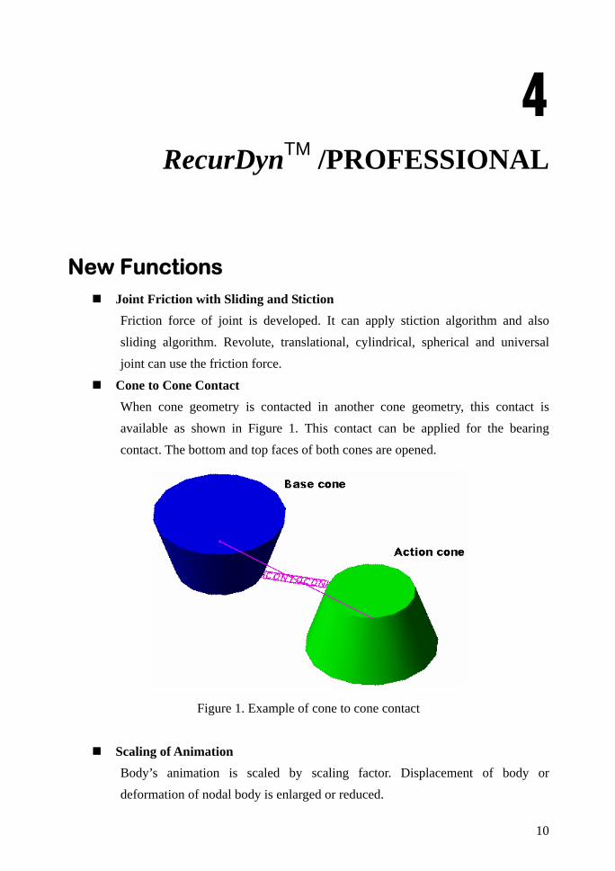
Cone to Cone Contact When cone geometry is contacted in another cone geometry, this contact is available as shown in Figure 1. This contact can be applied for the bearing contact. The bottom and top faces of both cones are opened.
Figure 1. Example of cone to cone contact
Scaling of Animation Body’s animation is scaled by scaling factor. Displacement of body or deformation of nodal body is enlarged or reduced.
10
Match Solving Stepsize with Report Step The solving step and report step can be coincided. The option in parameter dialog box decides to do it or not.
Upgraded Functions Message File
Message file (*.msg) have model name, simulation start date and time, end date and time.
Simple Math In plot simple math calculation dialog can modify or add a graph. Scaling the graph from Degree to Radian and vise versa is added.
Micro Unit Recurdyn can have micro unit.
Performance Index in Specified Time In design study, performance index is evaluated from user defined start time to end time.
Request file format Request file support 12 digit to provide precise results.
Floating Marker The position and orientation of floating marker are updated for PTCV, CVCV, Translational, Rotational and Screw Force. Plot output, marker trace and usage of expression are updated by this function. But in animation, floating marker moves with parent body like other general markers.
Numerical damping in hybrid integrator There is a concept of numerical damping in IMGALPHA integrator. It can control a whole system damping so that its value can make more stable system and control magnitude of oscillation. The hybrid integrator that is always activated whenever FFlex body exists in system had been set the numerical damping to maximum damping should be worked. But from this version, you can control this effect by manual input. The difference and effect of numerical damping are shown in below figure.
11
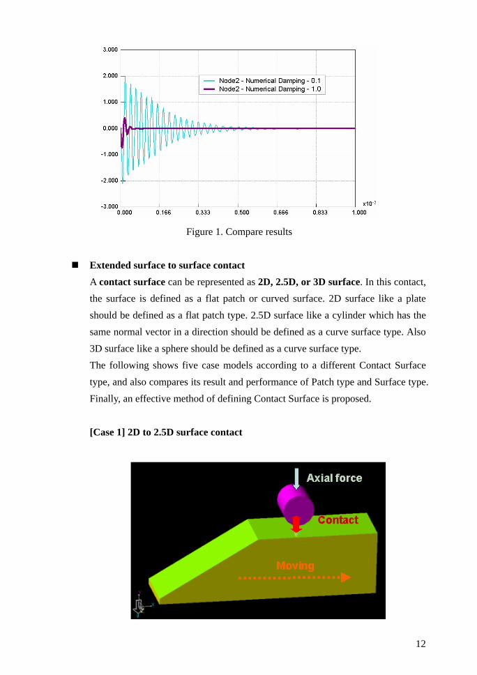
Figure 1. Compare results
Extended surface to surface contact A contact surface can be represented as 2D, 2.5D, or 3D surface. In this contact, the surface is defined as a flat patch or curved surface. 2D surface like a plate should be defined as a flat patch type. 2.5D surface like a cylinder which has the same normal vector in a direction should be defined as a curve surface type. Also 3D surface like a sphere should be defined as a curve surface type.
The following shows five case models according to a different Contact Surface type, and also compares its result and performance of Patch type and Surface type. Finally, an effective method of defining Contact Surface is proposed.
[Case 1] 2D to 2.5D surface contact
12
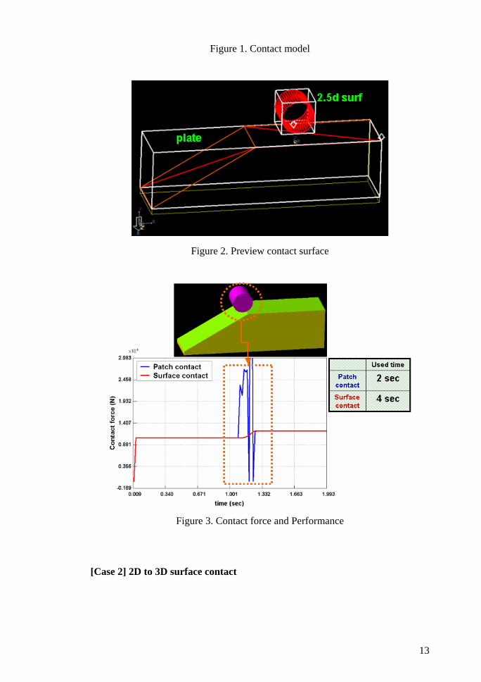
Figure 1. Contact model
Figure 2. Preview contact surface
Figure 3. Contact force and Performance
[Case 2] 2D to 3D surface contact
13
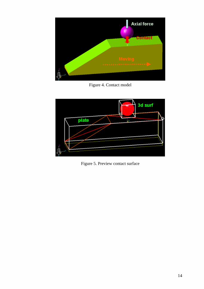
Figure 4. Contact model
Figure 5. Preview contact surface
14
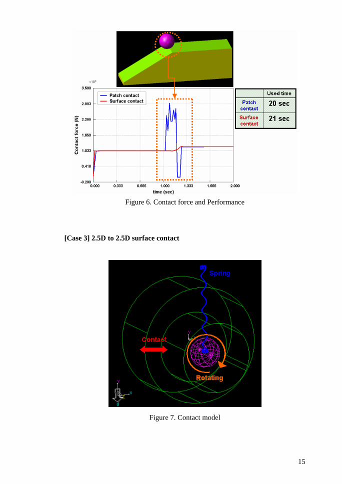
Figure 6. Contact force and Performance
[Case 3] 2.5D to 2.5D surface contact
Figure 7. Contact model
15
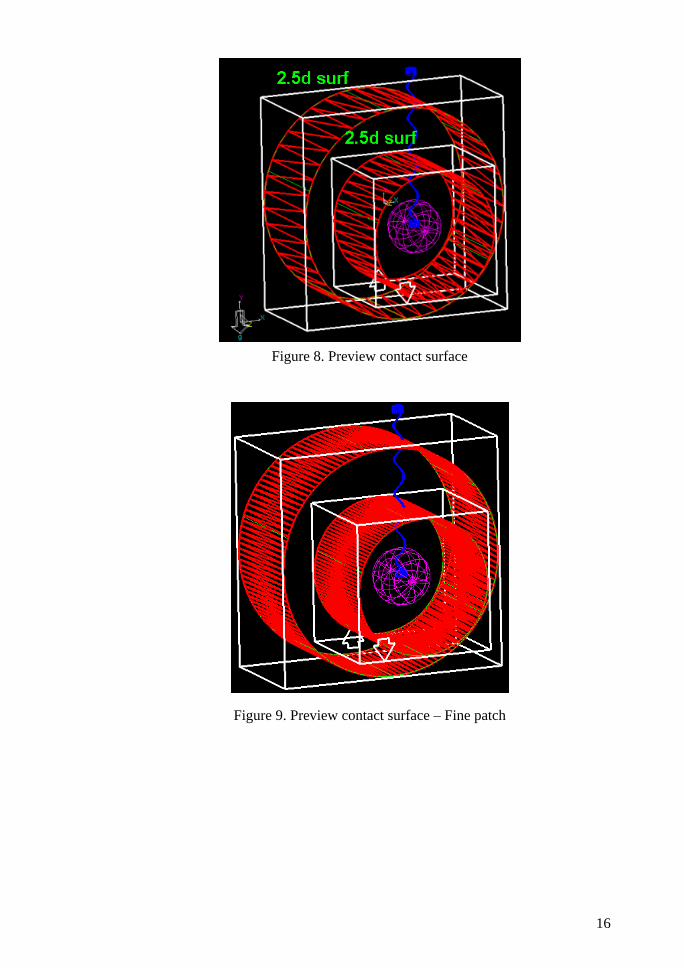
Figure 8. Preview contact surface
Figure 9. Preview contact surface – Fine patch
16
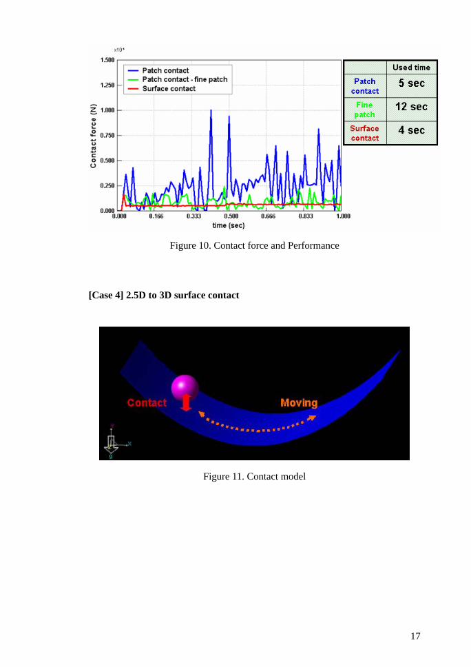
Figure 10. Contact force and Performance
[Case 4] 2.5D to 3D surface contact
Figure 11. Contact model
17
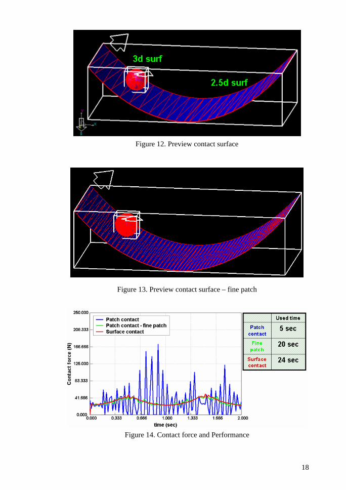
Figure 12. Preview contact surface
Figure 13. Preview contact surface – fine patch
Figure 14. Contact force and Performance
18
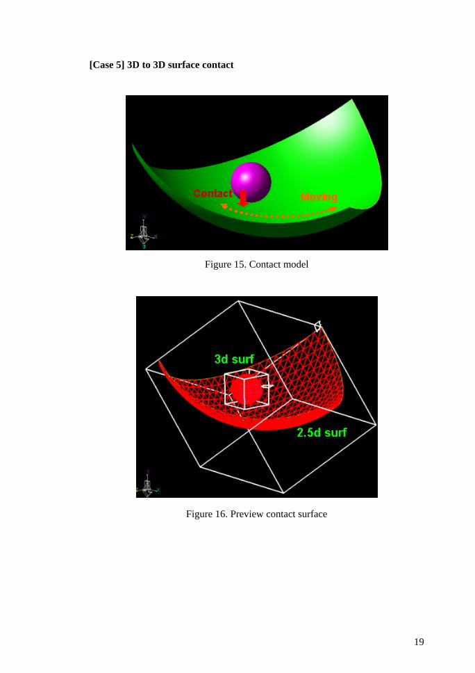
[Case 5] 3D to 3D surface contact
Figure 15. Contact model
Figure 16. Preview contact surface
19
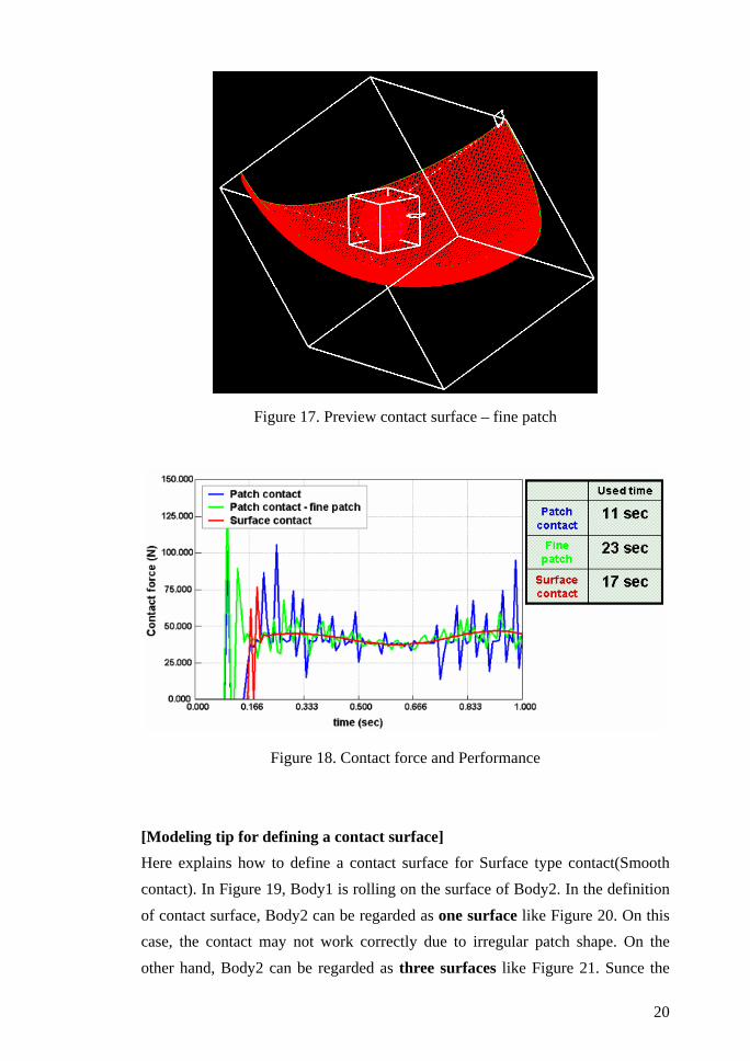
Figure 17. Preview contact surface – fine patch
Figure 18. Contact force and Performance
[Modeling tip for defining a contact surface] Here explains how to define a contact surface for Surface type contact(Smooth contact). In Figure 19, Body1 is rolling on the surface of Body2. In the definition
of contact surface, Body2 can be regarded as one surface like Figure 20. On this case, the contact may not work correctly due to irregular patch shape. On the
other hand, Body2 can be regarded as three surfaces like Figure 21. Sunce the
20
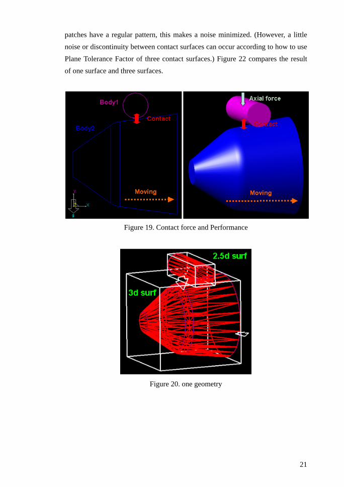
patches have a regular pattern, this makes a noise minimized. (However, a little noise or discontinuity between contact surfaces can occur according to how to use Plane Tolerance Factor of three contact surfaces.) Figure 22 compares the result of one surface and three surfaces.
Figure 19. Contact force and Performance
Figure 20. one geometry
21
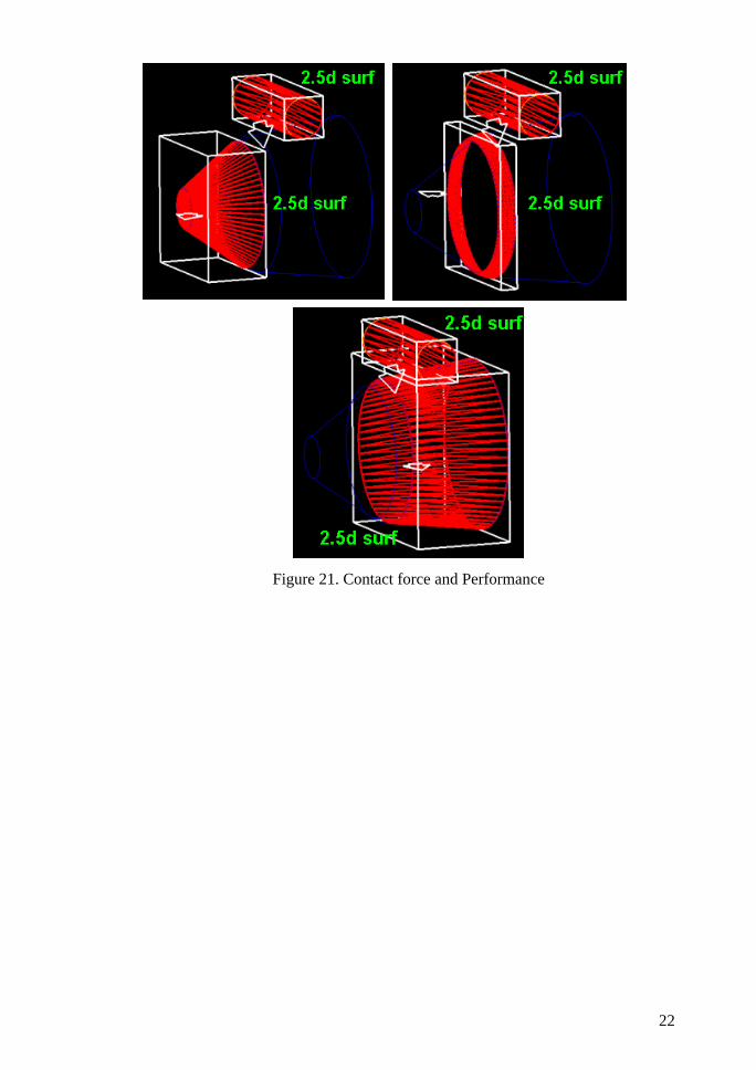
Figure 21. Contact force and Performance
22
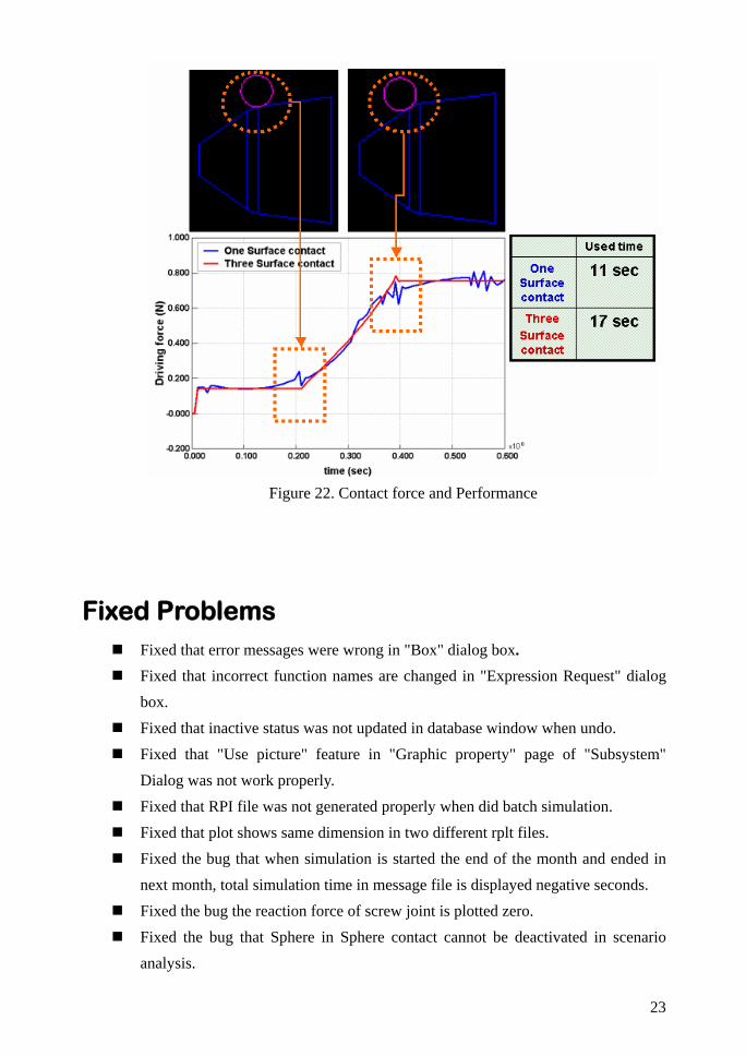
Figure 22. Contact force and Performance
Fixed Problems
Fixed that error messages were wrong in "Box" dialog box. Fixed that incorrect function names are changed in "Expression Request" dialog
box. Fixed that inactive status was not updated in database window when undo. Fixed that "Use picture" feature in "Graphic property" page of "Subsystem"
Dialog was not work properly. Fixed that RPI file was not generated properly when did batch simulation. Fixed that plot shows same dimension in two different rplt files. Fixed the bug that when simulation is started the end of the month and ended in
next month, total simulation time in message file is displayed negative seconds. Fixed the bug the reaction force of screw joint is plotted zero. Fixed the bug that Sphere in Sphere contact cannot be deactivated in scenario
analysis.
23

Fixed the bug that Cone in Cone contact cannot be deactivated in scenario analysis.
24
5 RecurDynTM/FFLEX
Upgraded Functions Select method
There was only a way to make a selection area. It was a two point box method. It was generally helpful but had some limitation for selecting target that lay on curved or more complicate geometry. So RecurDyn / FFlex add another two types of method to define selection area more easily. The point radius method can be helpful to select a hole type geometry and multipoint polygon method can cover all general geometries. You can use it only within FFlex edit mode.
RigidE created after extraction After extraction, FFlex body has two types of nodal positions. One is the original position that contains information before deformation and the other is current position that contains deformation. The original position always used in calculating element stiffness matrix and initial conditions. So if you create Rigid Element after extraction to hold some nodes, Rigid Element calculates initial conditions from original position and intends to go back to original position to satisfy initial conditions. In now, Rigid Element calculates initial conditions from current new position to overcome this problem.
Fixed Problems
FFlex body includes a lot of element type and each element has different nodal degree of freedom. Although previous version showed a D.O.F with wrong assumption that is all nodes has 6 D.O.F, current RecurDyn calculates correct D.O.F and shows it right after Pre analysis in message window.
25
In the beam property components, there is Y-direction vector that used for defining y-axis of area moment of inertia. This vector is defined with respect to FFlex body reference frame. So, when you analysis the system, it should be transformed to global one to consider the FFlex body’s own orientation. In previous version, the FFlex body’s orientation was not considered and it is fixed.
Some of Fsurface to surface contact data had been imposed to change because of hyperelastic material data. It makes unstable system and finally caused to be diverged. It is fixed.
When you import an FFlex input file that exported from DesignSpace, RecurDyn was not give correct relation between element and property. It is fixed.
The stress and strain recovery routine has a little problem to handle a system that contains rubber material and requires very large animation steps. The problem did not any effect on the stress and strain result but cause a crash of RecurDyn. It is fixed.
RecurDyn has a force unit independent of base unit (length-mass-time). So there should be converting factor between force and base unit. When you use Rigid Element of force type, the converting factor was not considered. It is fixed.
Known Problem Total mass and inertia value of FFlex body are slightly different from previous
version because of precision problem. It does not make any difference on general nodal flexible analysis except only swap analysis because total mass and inertia represent a rigid property of swapped FFlex body.
New two types(Multipoint polygon method, Point radius method) of select method cannot be used to select Patch Set, Node Set, and B.C.
26

6 RecurDynTM/RFLEX
Upgraded Functions IDEAS interface
RFI file(RFlex input file) can be generated from a result file(universal file) of IDEAS 12 version.
Fixed Problems
Fixed the problem that mass and inertia were shown without converting RFlex units.
27
7 RecurDynTM/BELT
Upgraded Functions Beam Belt
RecurDyn/Belt supports the function of Beam Belt to create the continuous belt model using beam element. Beam Belt and Belt Group use beam element but there ate different functions between Beam Belt and Belt Group. In comparison of Beam Belt, Belt Group have rectangular and trapezoidal shapes, Belt Group can use user matrix instead of beam, but Belt Group can’t use the functionalities of FFlex. Beam Belt doesn’t have a special shape, but uses a virtual shape for contact. Beam Belt can’t use user matrix instead of beam, but Beam Belt can use all functionalities of FFlex. Because the functionalities of FFlex, we recommend you to use Beam Belt instead of Belt Group.
Fixed Problems Fixed the bug that the distance sensor couldn’t to sense the distance from the
distance sensor to the side of Shell Belt. Fixed the bug that the elastic forces of node of Belt Group and Shell Belt differed
between elements in plot. Fixed the bug that the tension of node of Shell Belt was half the tension of Belt
element. Fixed the bug that the flange didn’t contact timing belts in a segment assembly. Fixed the bug that the convex curve of the timing pulley didn’t contact the
concave curve of timing belts in a segment assembly.
28
8 RecurDynTM/CHAIN
Upgraded Functions Multiple arc group guide
Group Guides have been formally created using only single arc so far. In now, users can create group guides by multiple arcs definition..
Additional output Additional contact force plot data based on sprockets, guides and group guides is showed when contact occurred between components (ex. links to sprockets, links to guides, links to group guides). Especially, the contact force between links and group guides is showed as a summation force.
Single Inner Link (Hy-vo chain) in Silent chain Links of silent chain consist of outer links and inner links. The shape of inner link was only double link type. Now, single link type of inner link can be created.
29
9 RecurDynTM/CONTROL
Upgraded Functions RecurDyn host mode
For the co-simulation between RecurDyn and Simulink, Simulink was a host and RecurDyn was a client. RecurDyn can be the host for the convenience of a plant designer.
Fixed Problems The command to create RecurDyn Plant Block in Simulink is rdlib. Because this
name wasn’t exactly equal to the name of file, the warming message appeared in Simulink. The file name to create RecurDyn Plant Block in Simulink is revised.
30
10 RecurDynTM/MTT2D
New Functions Nodal force for a sheet group
You can apply nodal forces on bodies of a sheet group. The forces maybe are attraction force between the belt and the sheet due to vacuum, electrostatic force between papers and rollers, and air resistance force. You can program a user subroutine with C/C++ or FORTRAN languages. Returned values from the subroutine should be a force and torque that they are generalized at the center of the each body in the global reference frame.
Guide converter You can convert a geometry defined from a CAD into a guide at once. Line and arc geometry are converted into the linear and arc guides, respectively. Circle geometry is converted into the pseudo-guide edge. After you import CAD geometries, you simultaneously and easily create a number of guides if you use the guide converter function and the body merge tool.
Upgraded Functions Nodal output for a sheet group
Simulation results of a specified body in a sheet group can be plotted in the scope and plotter. The results in the plotter include such as a contact force and its impulse, and nodal forces generalized at the center of the body. The results in the scope include such as the position, velocity and acceleration of the body.
31
11 RecurDynTM/MTT3D
Fixed Problems Fixed the bug that an initial velocity of a sheet shell or sheet group doesn’t work.
32
12 RecurDynTM/MMS
New Function MMS type C
Multi Mass Spring Type C is composed of a geometric spring shape and Multi
Mass bodies (spheres) which are connected with translational joints and axial force. The axial force represents nonlinear stiffness characteristics between Multi Mass Bodies. There are two types of spring which are One-Step and Two-Step. They are different in the nonlinear character.
MMS type D The MMS Type D, 3D Multi Mass Spring is composed of a geometric spring shape and Multi Mass bodies which are connected with beam forces and contact forces for analyzing contact situations. The beam force which is defined by beam properties (Young’s modulus, shear modulus, cross section area, etc.) represents nonlinear stiffness characteristics between Multi Mass Bodies. Two kinds of contact force can be defined for MMS Type D. The one is for the contact situation between up and down of helix of the spring. The other is for the contact situation between two MMS type D springs.
33
13 RecurDynTM/CRANK
Upgraded Functions Spline type stiffness and damping You could use only coefficient type for definition of stiffness and damping in bush bearing between components of crank system (ex. between crank shaft and big eye of con-rod) formally. However, you can also use spline type in order to input a specific curve data.
Fixed Problems A request function handled as a dummy should not have been considered to make
*.req file which is generated when request function is operated. However, it was considered to make *.req file. That’s why, wrong *.req file including inavailable information was generated. So, making wrong *.req file was fixed not to consider when a request function is dummy.
34
Copyright © 2006 FunctionBay, Inc. All rights reserved User and training documentation from FunctionBay, Inc. is subjected to the copyright laws of the Republic of Korea and other countries and is provided under a license agreement that restricts copying, disclosure, and use of such documentation. FunctionBay, Inc. hereby grants to the licensed user the right to make copies in printed from of this documentation if provided on software media, but only for internal/personal use and in accordance with the license agreement under which the applicable software is licensed. Any copy made shall include the FunctionBay, Inc. copyright notice and any other proprietary notice provided by FunctionBay, Inc. This documentation may not be disclosed, transferred, modified, or reduced to any form, including electronic media, or transmitted or made publicly available by any means without the prior written consent of FunctionBay, Inc. and no authorization is granted to make copies for such purpose. Information described herein is furnished for general information only, is subjected to change without notice, and should not be construed as a warranty or commitment by FunctionBay, Inc. FunctionBay, Inc. assumes no responsibility or liability for any errors or inaccuracies that may appear in this document. The software described in this document is provided under written license agreement, contains valuable trade secrets and proprietary information, and is protected by the copyright laws of the Republic of Korea and other countries. UNAUTHORIZED USE OF SOFTWARE OR ITS DOCUMENTATION CAN RESULT IN CIVIL DAMAGES AND CRIMINAL PROSECUTION. Registered Trademarks of FunctionBay, Inc. or Subsidiary RecurDyn™ is a registered trademark of FunctionBay, Inc. RecurDyn™/Professional, RecurDyn™/Solver, RecurDyn™/Solid, RecurDyn™/FFlex, RecurDyn™/RFlex, RecurDyn™/Linear, RecurDyn™/Control, RecurDyn™/Driver, RecurDyn™/Tire, RecurDyn™/TRACK_HM, RecurDyn™/TRACK_LM, RecurDyn™/Chain, RecurDyn™/MTT2D, RecurDyn™/MTT3D, RecurDyn™/Belt, RecurDyn™/HAT, RecurDyn™/Gear, RecurDyn™/Bearing, RecurDyn™/Crank, RecurDyn™/Piston, RecurDyn™/MMS, RecurDyn™/EHD, RecurDyn™/Hydraulic RecurDyn™/CoLink, RecurDyn™/AutoDesign, RecurDyn™/Mesh Interface
are trademarks of FunctionBay, Inc.
35
Third-Party Trademarks Windows and Windows NT are registered trademarks of Microsoft Corporation. ProENGINEER and ProMECHANICA are registered trademarks of PTC Corp. Unigraphics is a registered trademark of EDS Corp. I-DEAS is a registered trademark of SDRC. SolidWorks is a registered trademark of SolidWorks Corp. AutoCAD is a registered trademark of Autodesk, Inc. CADAM and CATIA are registered trademark of Dassault Systems. FLEXlm is a registered trademark of GLOBEtrotter Software, Inc. All other brand or product names are trademarks or registered trademarks of their respective holders. UNITED STATES GOVERNMENT RESTRICTED RIGHTS LEGEND This document and the software described herein are Commercial Computer Documentation and Software, pursuant to FAR 12.212(a)-(b) or DFARS 227.7202-1(a) and 227.7202-3(a), and are provided to the Government under a limited commercial license only. For procurements predating the above clauses, use, duplication, or disclosure by the Government is subjected to the restrictions set forth in subparagraph (c)(1)(ii) of the Rights in Technical Data and Computer Software Clause at DFARD 252.227-7013 or Commercial Computer Software-Restricted Rights at FAR 52.227-19, as applicable.
Edition Note
This document describes the release information of RecurDyn™ V. 6.3
36