Embed Size (px)
Citation preview
Recycling carbon fibre reinforced polymers for
structural applications: technology review and market outlook
Soraia Pimenta∗, Silvestre T. Pinho
The Composites Centre, Department of Aeronautics, South Kensington Campus, Imperial CollegeLondon. London SW7 2AZ, United Kingdom
Abstract
Both environmental and economic factors have driven the development of recyclingroutes for the increasing amount of carbon fibre reinforced polymer (CFRP) wastegenerated. This paper presents a review of the current status and outlook of CFRP re-cycling operations, focusing on state–of–the–art fibre reclamation and re-manufacturingprocesses, and on the commercialisation and potential applications of recycled prod-ucts. It is shown that several recycling and re-manufacturing processes are reaching amature stage, with implementations at commercial scales in operation, production ofrecycled CFRPs having competitive structural performances, and demonstrator com-ponents having been manufactured. The major challenges for the sound establishmentof a CFRP recycling industry and the development of markets for the recyclates aresummarised; the potential for introducing recycled CFRPs in structural components isdiscussed, and likely promising applications are investigated.
Keywords: Carbon fibre reinforced polymers, Recycling, Fibre reclamation,Manufacturing Structural applications,
1. Introduction
The increasing use of carbon fibre reinforced polymers (CFRPs) has raised an en-vironmental and economic awareness for the need to recycle the CFRP waste. Thelatest governmental UK strategy for composites (BIS 2009) identifies “Increasing Sus-tainability and Recycling” as one of the three major goals for the composites industry.In this paper, the current status of recycling processes for CFRP and the forthcomingchallenges for the introduction of the recyclates in structural applications are reviewed.
The world–wide demand for carbon fibres (CFs) reached approximately 35, 000 t in2008; this number is expected to double by 2014, representing a growth rate of over 12%per year (Roberts 2009). CFRP is now used in a widening range of applications, andin growing content in most of them (Sloan 2008); the aircraft industry is an impressive
∗Corresponding author.Email address: [email protected] (Soraia Pimenta)
Pimenta S, Pinho ST (2011). Recycling carbon fibre reinforced polymers for structuralapplications: technology review and market outlook. Waste Management 31, 378–392.DOI:10.1016/j.wasman.2010.09.019
NomenclatureVariablesE Young’s modulusGc fracture toughnessl lengthS shear strengthU energy absorptionV volume fractionX uniaxial strength
Superscriptsf fibre
Subscriptsavg averageIF interfacialimp impactT tensile
example, with the new Boeing 787 and Airbus A350 having up to 50% of their weightin CFRP, and military aircraft showing a similar trend (Marsh 2008).
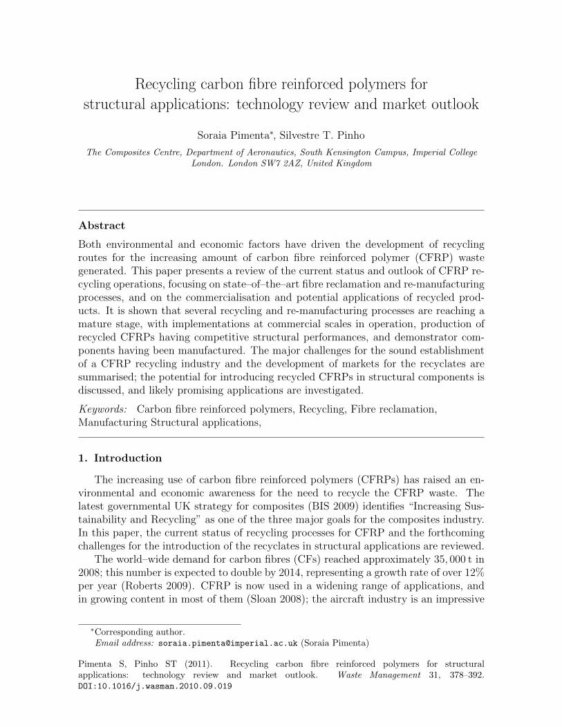
Despite all advantages associated with CFRPs, the increasing use generates an alsoincreasing amount of CFRP waste. Common sources of waste include out–of–date pre-pregs, manufacturing cut–offs, testing materials, production tools and end–of–life (EoL)components (Figure 1); manufacturing waste is approximately 40% of all the CFRPwaste generated (Pickering et al. 2006), while woven trimmings contribute with morethan 60% to this number (Hunter 2009). Continuing with the aeronautics sector as ex-ample, the first aircraft with structural CFRP components will soon be decommissioned(Marsh 2008); within 30 years, the same will happen to the new composite–generationaircraft (8, 500 commercial planes will be retired by 2025, Carberry 2008), with eachvehicle representing more than 20 t of CFRP waste (Roberts 2007). Within a simi-lar time frame, the wind industry will be another great source of CFRP waste (Wood2010).
Recycling composites is inherently difficult because of (i) their complex composi-tion (fibres, matrix and fillers), (ii) the cross–linked nature of thermoset resins (whichcannot be remoulded), and (iii) the combination with other materials (metal fixings,honeycombs, hybrid composites, etc.). Presently, most of the CFRP waste is landfilled(Pickering 2006); the airframe of EoL vehicles is usually disposed in desert graveyards,airports, or by landfilling (Carberry 2008, PAMELA 2005). However, these are unsat-isfactory solutions for several reasons:
• Environmental impact: the increasing amount of CFRP produced raises concernson waste disposal and consumption of non-renewable resources.
• Legislation: recent European legislation is enforcing a strict control of compositedisposal; the responsibility of disposing EoL composites is now on the component’smanufacturer, legal landfilling of CFRP is limited, and for instance it is requiredthat automotive vehicles disposed after 2015 are 85% recyclable (EU 1999/31/EC1999, EU 2000/53/EC 2000).
• Production cost: CFs are expensive products, both in terms of energy consumedduring manufacturing (up to 165 kWh/kg) and material price (up to 40 £/kg)(Carberry 2008).
2
(a) Out-of-date prepreg rolls. (b) Manufacturing cut–offs.
(c) Yatch mould. (d) EoL–aircraft wings.
Figure 1: CFRP waste (Panesar 2009).
• Management of resources: demand of virgin (v-) CFs usually surpasses supply–capacity (Roberts 2007), so recycled (r-) CFs could be re-introduced in the marketfor non-critical applications (Carberry 2009).
• Economic opportunity: disposing of CFRP by landfilling, where not illegal, cancost approximately 0.20 £/kg (Meyer et al. 2007); recycling would convert anexpensive waste disposal into a profitable reusable material.
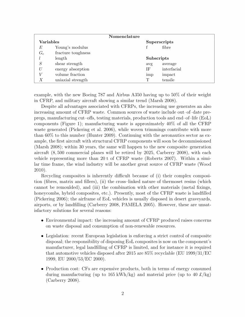
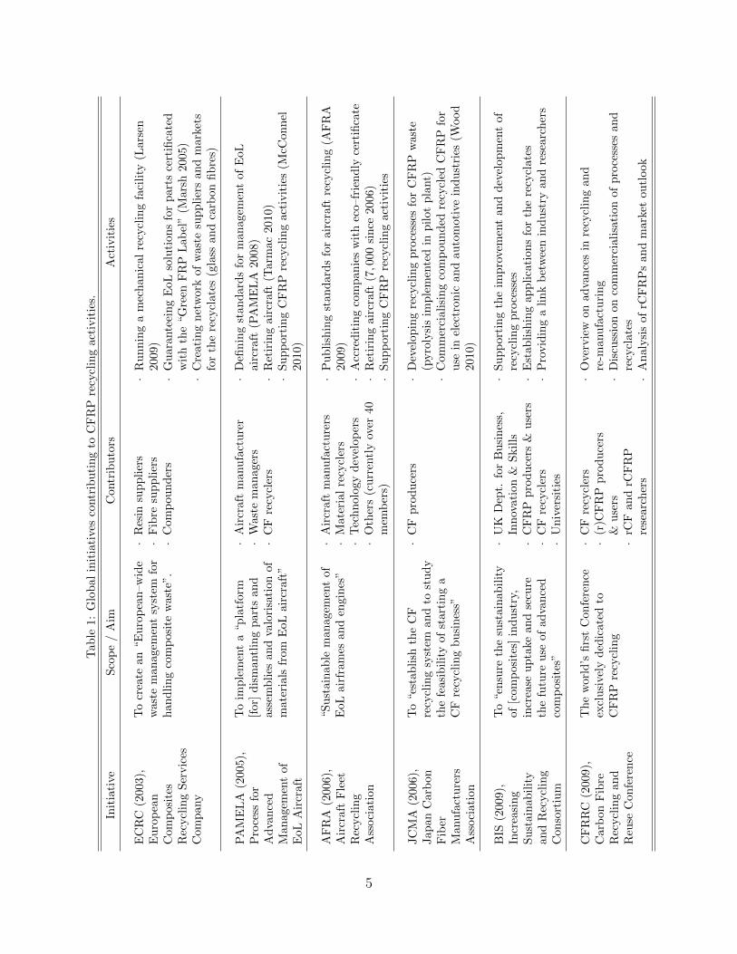
It is clear that turning CFRP waste into a valuable resource and closing the loopin the CFRP life–cycle (Figure 2) is vital for the continued use of the material in someapplications, e.g. the automotive industry (Pickering 2006). This need has driven notonly a great amount of research on recycling processes for CFRPs over the last 15 years,but also the formation of several collaborative entities working on a more commercialor industrial level (Table 1).
Some review papers on carbon–fibre recycling are available in the literature; DeRosaet al. (2005) and Pickering (2006) focused on established recycling processes, while Mc-Connel (2010) and Wood (2010) discussed their implementation at commercial scales.However, there is a strong connection between recycling, re-manufacturing processesand the final performance of the recyclates (Pimenta et al. 2010a); this clearly affectsthe type of markets in which rCFs can be introduced, which has a great impact forany commercial recycling operation (Line 2009). Processes, performance, commerciali-
3
(ii) vCFRP component
(i) vCFs (iii) CFRP waste
(iv) rCFs(v) rCFRP component
Recycling
Re-manufacturing
References:(i) Connor 2008;(ii) NASA 1991;(iii) Marsh 2008;(iv) Connor 2008;(v) Janney et al. 2009.
Figure 2: Closed life–cycle for CFRPs.
sation and markets must therefore be considered altogether if a comprehensive analysisof CFRP recycling operations is envisaged.
This paper aims to fulfill this need: on the one hand, it encompasses the latesttechnical developments and the forthcoming commercialisation challenges; on the otherhand, it relates the existing recycling and re-manufacturing processes to the final recy-clates and their respective potential market applications.
The paper is organised as follows: Section 2 establishes the state of the art in carbonfibre recycling. Section 3 analyses re-manufacturing of recycled composites using rCFs.Section 4 discusses achievements and current issues with recycling operations, includ-ing technical, commercial and marketing considerations, all in the scope of structuralapplications. Finally, the main conclusions are summarised in Section 5.
4
Tab
le1:
Glo
bal
init
iati
ves
contr
ibu
tin
gto
CF
RP
recy
clin
gact
ivit
ies.
Init
iati
veS
cop
e/
Aim
Contr
ibu
tors
Act
ivit
ies
EC
RC
(200
3),
Eu
rop
ean
Com
pos
ites
Rec
ycl
ing
Ser
vic
esC
omp
any
To
crea
tean
“Eu
rop
ean
–w
ide
was
tem
anag
emen
tsy
stem
for
han
dli
ng
com
pos
ite
wast
e”.
·R
esin
sup
pli
ers
·F
ibre
sup
pli
ers
·C
om
pou
nd
ers
·R
un
nin
ga
mec
han
ical
recy
clin
gfa
cili
ty(L
ars
en2009)
·G
uara
nte
ein
gE
oL
solu
tion
sfo
rp
art
sce
rtifi
cate
dw
ith
the
“G
reen
FR
PL
ab
el”
(Mars
h2005)
·C
reati
ng
net
work
of
wast
esu
pp
lier
san
dm
ark
ets
for
the
recy
clate
s(g
lass
an
dca
rbon
fib
res)
PA
ME
LA
(200
5),
Pro
cess
for
Ad
van
ced
Man
agem
ent
ofE
oLA
ircr
aft
To
imp
lem
ent
a“p
latf
orm
[for
]d
ism
antl
ing
part
san
das
sem
bli
esan
dva
lori
sati
on
of
mat
eria
lsfr
omE
oLai
rcra
ft”
·A
ircr
aft
manu
fact
ure
r·
Wast
em
an
ager
s·
CF
recy
cler
s
·D
efin
ing
stan
dard
sfo
rm
an
agem
ent
of
EoL
air
craft
(PA
ME
LA
2008)
·R
etir
ing
air
craft
(Tarm
ac
2010)
·S
up
port
ing
CF
RP
recy
clin
gact
ivit
ies
(McC
on
nel
2010)
AF
RA
(200
6),
Air
craf
tF
leet
Rec
ycl
ing
Ass
oci
atio
n
“Su
stai
nab
lem
anag
emen
tof
EoL
airf
ram
esan
den
gin
es”
·A
ircr
aft
manu
fact
ure
rs·
Mate
rial
recy
cler
s·
Tec
hn
olo
gy
dev
elop
ers
·O
ther
s(c
urr
entl
yov
er40
mem
ber
s)
·P
ub
lish
ing
stan
dard
sfo
rair
craft
recy
clin
g(A
FR
A2009)
·A
ccre
dit
ing
com
pan
ies
wit
hec
o–fr
ien
dly
cert
ifica
te·
Ret
irin
gair
craft
(7,0
00
sin
ce2006)
·S
up
port
ing
CF
RP
recy
clin
gact
ivit
ies
JC
MA
(200
6),
Jap
anC
arb
onF
iber
Man
ufa
ctu
rers
Ass
oci
atio
n
To
“est
abli
shth
eC
Fre
cycl
ing
syst
eman
dto
stu
dy
the
feas
ibil
ity
ofst
art
ing
aC
Fre
cycl
ing
bu
sin
ess”
·C
Fp
rod
uce
rs·
Dev
elop
ing
recy
clin
gp
roce
sses
for
CF
RP
wast
e(p
yro
lysi
sim
ple
men
ted
inp
ilot
pla
nt)
·C
om
mer
ciali
sin
gco
mp
ou
nd
edre
cycl
edC
FR
Pfo
ru
sein
elec
tron
ican
dau
tom
oti
vein
du
stri
es(W
ood
2010)
BIS
(200
9),
Incr
easi
ng
Su
stai
nab
ilit
yan
dR
ecycl
ing
Con
sort
ium
To
“en
sure
the
sust
ain
ab
ilit
yof
[com
pos
ites
]in
du
stry
,in
crea
seu
pta
kean
dse
cure
the
futu
reuse
ofad
van
ced
com
pos
ites
”
·U
KD
ept.
for
Bu
sin
ess,
Inn
ovati
on
&S
kil
ls·
CF
RP
pro
du
cers
&u
sers
·C
Fre
cycl
ers
·U
niv
ersi
ties
·S
up
port
ing
the
imp
rovem
ent
an
dd
evel
op
men
tof
recy
clin
gp
roce
sses
·E
stab
lish
ing
ap
pli
cati
on
sfo
rth
ere
cycl
ate
s·
Pro
vid
ing
ali
nk
bet
wee
nin
dust
ryan
dre
searc
her
s
CF
RR
C(2
009)
,C
arb
onF
ibre
Rec
ycl
ing
and
Reu
seC
onfe
ren
ce
Th
ew
orld
’sfi
rst
Con
fere
nce
excl
usi
vely
ded
icat
edto
CF
RP
recy
clin
g
·C
Fre
cycl
ers
·(r
)CF
RP
pro
du
cers
&u
sers
·rC
Fan
drC
FR
Pre
searc
her
s
·O
verv
iew
on
ad
van
ces
inre
cycl
ing
an
dre
-manu
fact
uri
ng
·D
iscu
ssio
non
com
mer
ciali
sati
on
of
pro
cess
esan
dre
cycl
ate
s·
An
aly
sis
of
rCF
RP
san
dm
ark
etou
tlook
5
2. Carbon fibre recycling processes
2.1. Technology families
2.1.1. Overview
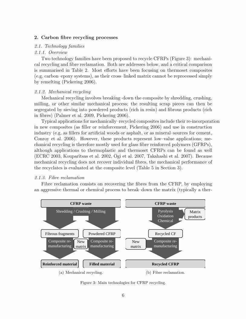
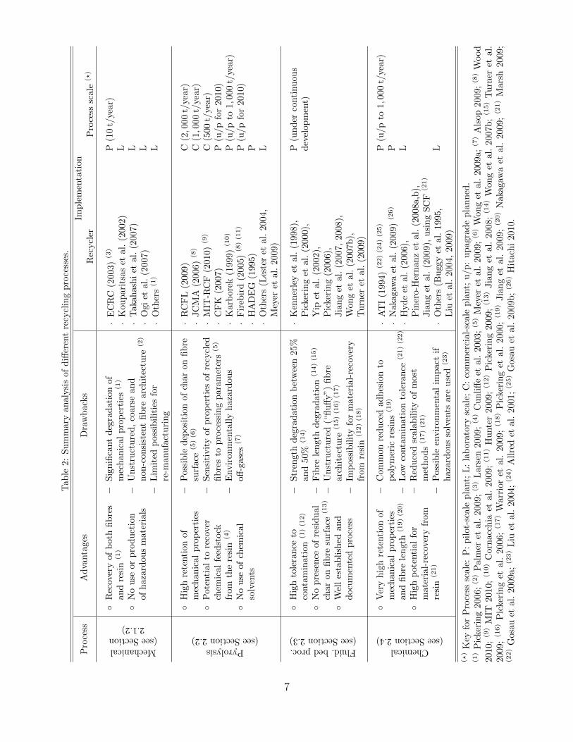
Two technology families have been proposed to recycle CFRPs (Figure 3): mechani-cal recycling and fibre reclamation. Both are addresses below, and a critical comparisonis summarised in Table 2. Most efforts have been focusing on thermoset composites(e.g. carbon–epoxy systems), as their cross–linked matrix cannot be reprocessed simplyby remelting (Pickering 2006).
2.1.2. Mechanical recycling
Mechanical recycling involves breaking–down the composite by shredding, crushing,milling, or other similar mechanical process; the resulting scrap pieces can then besegregated by sieving into powdered products (rich in resin) and fibrous products (richin fibres) (Palmer et al. 2009, Pickering 2006).
Typical applications for mechanically–recycled composites include their re-incorporationin new composites (as filler or reinforcement, Pickering 2006) and use in constructionindustry (e.g. as fillers for artificial woods or asphalt, or as mineral–sources for cement,Conroy et al. 2006). However, these products represent low–value applications; me-chanical recycling is therefore mostly used for glass fibre reinforced polymers (GFRPs),although applications to thermoplastic and thermoset CFRPs can be found as well(ECRC 2003, Kouparitsas et al. 2002, Ogi et al. 2007, Takahashi et al. 2007). Becausemechanical recycling does not recover individual fibres, the mechanical performance ofthe recyclates is evaluated at the composite level (Table 5 in Section 3).
2.1.3. Fibre reclamation
Fibre reclamation consists on recovering the fibres from the CFRP, by employingan aggressive thermal or chemical process to break–down the matrix (typically a ther-
Composite re-
manufacturing
Composite re-
manufacturing
Reinforced material
Fibrous fragments
New
matrix
Filled material
Powdered CFRP
Shredding / Crushing / Milling
CFRP waste
(a) Mechanical recycling.
Composite re-
manufacturing
Pyrolysis
Oxidation
Chemical
CFRP waste
Recycled CFRP
Matrix
products
Recycled CF
New
matrix
(b) Fibre reclamation.
Figure 3: Main technologies for CFRP recycling.
6
Tab
le2:
Su
mm
ary
an
aly
sis
of
diff
eren
tre
cycl
ing
pro
cess
es.
Pro
cess
Ad
vanta
ges
Dra
wb
ack
sIm
ple
men
tati
on
Rec
ycl
erP
roce
sssc
ale
(?)
Mechanical(seeSection
2.1.2)◦
Rec
over
yof
bot
hfi
bre
san
dre
sin
(1)
◦N
ou
seor
pro
du
ctio
nof
haz
ard
ous
mat
eria
ls
−S
ign
ifica
nt
deg
rad
ati
on
of
mec
han
ical
pro
per
ties
(1)
−U
nst
ruct
ure
d,
coars
ean
dn
on-c
on
sist
ent
fib
rearc
hit
ectu
re(2
)
−L
imit
edp
oss
ibil
itie
sfo
rre
-manu
fact
uri
ng
·E
CR
C(2
003)
(3)
·K
ou
pari
tsas
etal.
(2002)
·T
aka
hash
iet
al.
(2007)
·O
gi
etal.
(2007)
·O
ther
s(1
)
P(1
0t/
year)
L L L L
Pyrolysis(seeSection2.2)
◦H
igh
rete
nti
onof
mec
han
ical
pro
per
ties
◦P
oten
tial
tore
cover
chem
ical
feed
stock
from
the
resi
n(4
)
◦N
ou
seof
chem
ical
solv
ents
−P
ossi
ble
dep
osi
tion
of
char
on
fib
resu
rface
(5)(6
)
−S
ensi
tivit
yof
pro
per
ties
of
recy
cled
fib
res
top
roce
ssin
gp
ara
met
ers
(5)
−E
nvir
on
men
tall
yh
aza
rdous
off-g
ase
s(7
)
·R
CF
L(2
009)
·JC
MA
(2006)
(8)
·M
IT-R
CF
(2010)
(9)
·C
FK
(2007)
·K
arb
ore
k(1
999)
(10)
·F
ireb
ird
(2005)
(8)(1
1)
·H
AD
EG
(1995)
·O
ther
s(L
este
ret
al.
2004,
Mey
eret
al.
2009)
C(2,0
00
t/ye
ar)
C(1,0
00
t/ye
ar)
C(5
00
t/ye
ar)
P(u
/p
for
2010)
P(u
/p
to1,
000
t/ye
ar)
P(u
/p
for
2010)
P L
Fluid.bedproc.(seeSection2.3)
◦H
igh
tole
ran
ceto
conta
min
atio
n(1
)(1
2)
◦N
op
rese
nce
ofre
sid
ual
char
onfi
bre
surf
ace
(13)
◦W
ell
esta
bli
shed
and
docu
men
ted
pro
cess
−S
tren
gth
deg
rad
ati
on
bet
wee
n25%
and
50%
(14)
−F
ibre
len
gth
deg
radati
on
(14)(1
5)
−U
nst
ruct
ure
d(“
flu
ffy”)
fib
rearc
hit
ectu
re(1
5)(1
6)(1
7)
−Im
poss
ibil
ity
for
mate
rial-
reco
very
from
resi
n(1
2)(1
8)
·K
enn
erle
yet
al.
(1998),
Pic
keri
ng
etal.
(2000),
Yip
etal.
(2002),
Pic
keri
ng
(2006),
Jia
ng
etal.
(2007,
2008),
Won
get
al.
(2007b
),T
urn
eret
al.
(2009)
P(u
nd
erco
nti
nu
ou
sd
evel
op
men
t)
Chemical(seeSection2.4)
◦V
ery
hig
hre
tenti
onof
mec
han
ical
pro
per
ties
and
fib
rele
ngt
h(1
9)(2
0)
◦H
igh
pot
enti
alfo
rm
ater
ial-
reco
ver
yfr
omre
sin
(21)
−C
omm
on
red
uce
dad
hes
ion
top
olym
eric
resi
ns
(19)
−L
owco
nta
min
ati
on
tole
ran
ce(2
1)(2
2)
−R
edu
ced
scala
bil
ity
of
most
met
hod
s(1
7)(2
1)
−P
ossi
ble
envir
on
men
tal
imp
act
ifh
azard
ou
sso
lven
tsare
use
d(2
3)
·A
TI
(1994)
(22)(2
4)(2
5)
·N
aka
gaw
aet
al.
(2009)
(26)
·H
yd
eet
al.
(2006),
Pin
ero-H
ern
an
zet
al.
(2008a,b
),Jia
ng
etal.
(2009),
usi
ng
SC
F(2
1)
·O
ther
s(B
uggy
etal.
1995,
Liu
etal.
2004,
2009)
P(u
/p
to1,
000
t/ye
ar)
P L L
(?)
Key
for
Pro
cess
scal
e:P
:p
ilot
-sca
lep
lant;
L:
lab
ora
tory
scale
;C
:co
mm
erci
al-
scale
pla
nt;
u/p:
up
agra
de
pla
nn
ed.
(1)
Pic
keri
ng
2006
;(2
)P
alm
eret
al.
2009
;(3
)L
ars
en2009;(4
)C
un
liff
eet
al.
2003;(5
)M
eyer
etal.
2009;(6
)W
on
get
al.
2009a;(7
)A
lsop
2009;(8
)W
ood
2010
;(9
)M
IT20
10;(1
0)
Cor
nac
chia
etal
.20
09;(1
1)
Hu
nte
r2009;(1
2)
Pic
keri
ng
2009;(1
3)
Jia
ng
etal.
2008;(1
4)
Won
get
al.
2007b
;(1
5)
Tu
rner
etal.
2009
;(1
6)
Pic
keri
ng
etal
.20
06;(1
7)
War
rior
etal.
2009;(1
8)
Pic
keri
ng
etal.
2000;(1
9)
Jia
ng
etal.
2009;(2
0)
Naka
gaw
aet
al.
2009;(2
1)
Mars
h2009;
(22)
Gos
auet
al.
2009
a;(2
3)
Liu
etal
.20
04;(2
4)
All
red
etal.
2001;(2
5)
Gosa
uet
al.
2009b
;(2
6)
Hit
ach
i2010.
7
moset); the fibres are released and collected, and either energy or molecules can berecovered from the matrix. Fibre reclamation may be preceded by preliminary opera-tions e.g. cleaning and mechanical size–reduction of the waste.
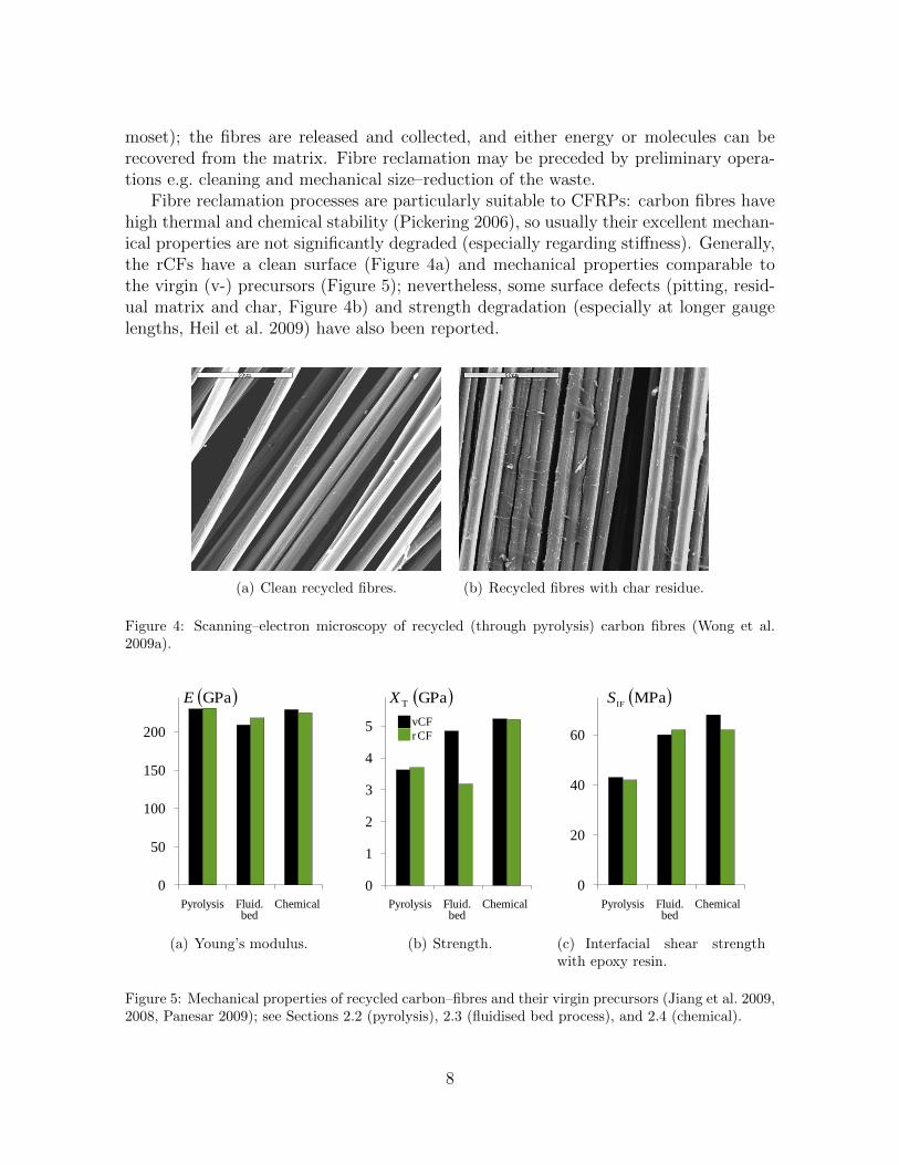
Fibre reclamation processes are particularly suitable to CFRPs: carbon fibres havehigh thermal and chemical stability (Pickering 2006), so usually their excellent mechan-ical properties are not significantly degraded (especially regarding stiffness). Generally,the rCFs have a clean surface (Figure 4a) and mechanical properties comparable tothe virgin (v-) precursors (Figure 5); nevertheless, some surface defects (pitting, resid-ual matrix and char, Figure 4b) and strength degradation (especially at longer gaugelengths, Heil et al. 2009) have also been reported.
(a) Clean recycled fibres. (b) Recycled fibres with char residue.
Figure 4: Scanning–electron microscopy of recycled (through pyrolysis) carbon fibres (Wong et al.2009a).
Pyrolysis ChemicalFluid.bed
0
50
100
150
200
GPaE
(a) Young’s modulus.
Pyrolysis ChemicalFluid.bed
0
1
2
3
4
5
GPaTX
vCF
rCF
(b) Strength.
Pyrolysis ChemicalFluid.bed
MPaIF
S
0
20
40
60
(c) Interfacial shear strengthwith epoxy resin.
Figure 5: Mechanical properties of recycled carbon–fibres and their virgin precursors (Jiang et al. 2009,2008, Panesar 2009); see Sections 2.2 (pyrolysis), 2.3 (fluidised bed process), and 2.4 (chemical).
8
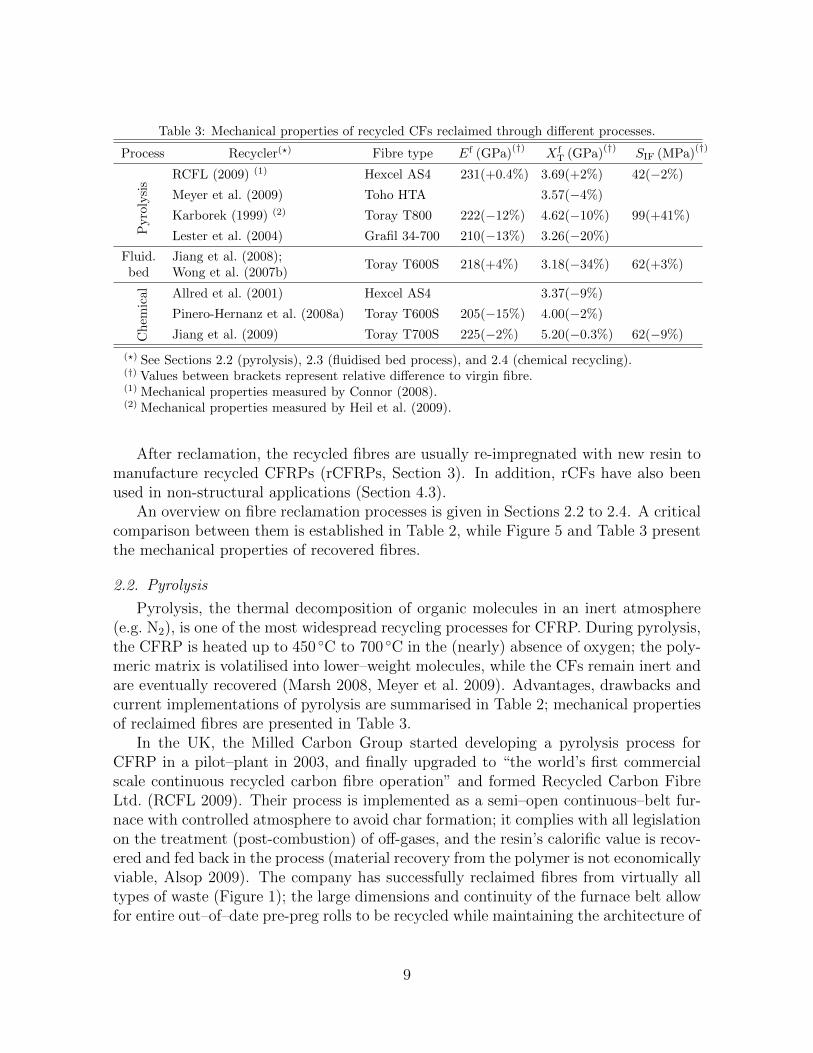
Table 3: Mechanical properties of recycled CFs reclaimed through different processes.
Process Recycler(?) Fibre type Ef (GPa)(†)
X fT (GPa)
(†)SIF (MPa)
(†)P
yro
lysi
s
RCFL (2009) (1) Hexcel AS4 231(+0.4%) 3.69(+2%) 42(−2%)
Meyer et al. (2009) Toho HTA 3.57(−4%)
Karborek (1999) (2) Toray T800 222(−12%) 4.62(−10%) 99(+41%)
Lester et al. (2004) Grafil 34-700 210(−13%) 3.26(−20%)
Fluid.bed
Jiang et al. (2008);Wong et al. (2007b)
Toray T600S 218(+4%) 3.18(−34%) 62(+3%)
Ch
emic
al Allred et al. (2001) Hexcel AS4 3.37(−9%)
Pinero-Hernanz et al. (2008a) Toray T600S 205(−15%) 4.00(−2%)
Jiang et al. (2009) Toray T700S 225(−2%) 5.20(−0.3%) 62(−9%)
(?) See Sections 2.2 (pyrolysis), 2.3 (fluidised bed process), and 2.4 (chemical recycling).(†) Values between brackets represent relative difference to virgin fibre.(1) Mechanical properties measured by Connor (2008).(2) Mechanical properties measured by Heil et al. (2009).
After reclamation, the recycled fibres are usually re-impregnated with new resin tomanufacture recycled CFRPs (rCFRPs, Section 3). In addition, rCFs have also beenused in non-structural applications (Section 4.3).
An overview on fibre reclamation processes is given in Sections 2.2 to 2.4. A criticalcomparison between them is established in Table 2, while Figure 5 and Table 3 presentthe mechanical properties of recovered fibres.
2.2. Pyrolysis
Pyrolysis, the thermal decomposition of organic molecules in an inert atmosphere(e.g. N2), is one of the most widespread recycling processes for CFRP. During pyrolysis,the CFRP is heated up to 450 ◦C to 700 ◦C in the (nearly) absence of oxygen; the poly-meric matrix is volatilised into lower–weight molecules, while the CFs remain inert andare eventually recovered (Marsh 2008, Meyer et al. 2009). Advantages, drawbacks andcurrent implementations of pyrolysis are summarised in Table 2; mechanical propertiesof reclaimed fibres are presented in Table 3.
In the UK, the Milled Carbon Group started developing a pyrolysis process forCFRP in a pilot–plant in 2003, and finally upgraded to “the world’s first commercialscale continuous recycled carbon fibre operation” and formed Recycled Carbon FibreLtd. (RCFL 2009). Their process is implemented as a semi–open continuous–belt fur-nace with controlled atmosphere to avoid char formation; it complies with all legislationon the treatment (post-combustion) of off-gases, and the resin’s calorific value is recov-ered and fed back in the process (material recovery from the polymer is not economicallyviable, Alsop 2009). The company has successfully reclaimed fibres from virtually alltypes of waste (Figure 1); the large dimensions and continuity of the furnace belt allowfor entire out–of–date pre-preg rolls to be recycled while maintaining the architecture of
9
the reinforcement. The group recently launched Green Carbon Fibre Ltd. (GCF 2010)for commercialisation of recycled products (e.g. milled and chopped fibres or pellets).
The Japan Carbon Fiber Manufacturers Association (JCMA 2006) started workingon CFRP recycling in 2006. JCMA currently runs a pyrolysis plant, but details on theprocess itself and mechanical properties of fibres have not been disclosed (Wood 2010).
In the USA, Materials Innovation Technologies RCF (MIT-RCF) was created by thehomonymous “advanced–materials solutions developer” company (MIT 2010), whichhad started recycling CFRP in 2008 using an undisclosed pyrolysis process (Janneyet al. 2009). Their approach includes a preliminary step of chopping the feedstockto a consistent length; after pyrolysis, an in–house developed manufacturing process(three dimensional engineered preforming, 3–DEP) proved to be particularly suitablefor re-manufacturing (Section 3).
In Germany, CFK Valley Stade Recycling GmbH & Co. KG (CFK 2007) uses acontinuous pyrolysis process (complemented with an oxidation step for char removal)developed together with the Technical University of Hamburg–Harburg and ReFiberApS (Meyer et al. 2007). The process is suitable for several types of CFRP waste, andthe main products comprise milled fibres, chopped fibres, and textile products (CFK2007, McConnel 2010).
In Italy, Karborek S.p.a. (Karborek 1999) uses a combined pyrolysis and upgrading(in oxygen) patented process to recycle the fibres and avoid char formation (Cornacchiaet al. 2009); although fibre–length is preserved during reclamation, Karborek’s mainproducts are milled and chopped rCFs, as well as blended non-woven veils with carbonand thermoplastic fibres (Section 3.3).
A variation of the pyrolysis process, using a continuous microwave approach (whichavoids char formation, Lester et al. 2004) has been implemented by Firebird AdvancedMaterials, Inc., in the USA (Hunter 2009).
In Germany, HADEG Recycling Ltd. (HADEG 1995, working in collaboration withthe Technical University of Hamburg–Harburg) reclaims CFs by pyrolysis, and alsocommercialises unprocessed manufacturing remainings (dry CF rovings or fabrics, anduncured pre-preg cut–offs).
2.3. Oxidation in fluidised bed
Oxidation is another thermal process for CFRP recycling; it consists in combustingthe polymeric matrix in a hot and oxygen–rich flow (e.g. air at 450 ◦C to 550 ◦C). Thismethod has been used by a few researchers (Jody et al. 2004), being the fluidised bedprocess (FBP) the most well–known implementation (Pickering 2006).
FBP has been developed and implemented by Pickering et al. (2000) at the Uni-versity of Nottingham. Advantages and drawbacks of FBP are summarised in Table 2;mechanical properties of the reclaimed fibres are presented in Table 3.
During recycling, CFRP scrap (reduced to fragments approximately 25 mm large)is fed into a bed of silica on a metallic mesh. As the hot air stream passes throughthe bed and decomposes the resin, both the oxidised molecules and the fibre filamentsare carried up within the air stream, while heavier metallic components sink in the
10
bed; this natural segregation makes the FBP particularly suitable for contaminatedEoL components. The fibres are separated from the air stream in a cyclone, and theresin is fully–oxidised in an afterburner; energy–recovery to feed the process is feasible(Pickering 2006, Pickering et al. 2000, Yip et al. 2002).
2.4. Chemical recycling
Chemical methods for CFRP recycling are based on a reactive medium — e.g. cat-alytic solutions (Allred et al. 2001), benzyl alcohol (Nakagawa et al. 2009), and super-critical fluids (Goto 2009, Jiang et al. 2009, Pinero-Hernanz et al. 2008a,b) — underlow temperature (typically < 350 ◦C). The polymeric resin is decomposed into rela-tively large (and therefore high value) oligomers, while the CFs remain inert and aresubsequently collected (Marsh 2009).
Advantages, drawbacks and current applications of chemical recycling are sum-marised in Table 2; mechanical properties of reclaimed fibres are presented in Table 3.
In the USA, Allred et al. (2001) developed a “catalytic tertiary recycling process”for CFRP, in Adherent Technologies, Inc. (ATI 1994). The standard method consistson a proprietary low–temperature liquid catalysis (Allred et al. 2001), although con-taminated waste may undergo a complementary dry pyrolysis step (Gosau et al. 2009a);with scrap preparation and post–treatment units, the whole process is automated andruns continuously (ATI 1994). The centre recycles both manufacturing waste (Allredet al. 2001, Gosau et al. 2009a) and EoL components (Connor 2008, Gosau et al. 2009b);the rCFs are marketed either milled or chopped, while resin products are recovered asfuels or chemical feedstock (ATI 1994).
In Japan, Nakagawa et al. (2009) developed a CF–epoxy recycling process usingbenzyl–alcohol and a catalyst in a N2 atmosphere. The plant (Hitachi 2010) includes adistillation system for cleaning the reaction fluid (which is then re-introduced in the sys-tem) and recovering resin–based products; it has reclaimed CFs from EoL componentsof sports and aeronautics industry.
Supercritical fluids (SCFs) are fluids at temperatures and pressures (typically just)above the critical point; at this stage, the fluid presents itself in one single supercriticalphase, while having combined characteristics: liquid–like density and dissolving power,and gas–like viscosity and diffusivity (Eckert et al. 1996). SCFs can therefore penetrateporous solids and dissolve organic materials, while still being relatively innocuous underatmospheric conditions (Hyde et al. 2006). Several types of SCF (usually coupled withalkali catalysts) have been used for CF recycling, such as water (Pinero-Hernanz et al.2008a), methanol (Pinero-Hernanz et al. 2008b), ethanol (Pinero-Hernanz et al. 2008b),acetone (Pinero-Hernanz et al. 2008b), and propanol (Hyde et al. 2006, Jiang et al. 2009,Pinero-Hernanz et al. 2008b). Chemical recycling with SCFs is a more recent approach;it is nevertheless already recognised for producing rCFs with virtually no mechanicaldegradation — especially when using propanol — and for allowing recovering usefulchemicals from the matrix (Marsh 2009, Pickering 2009, Warrior et al. 2009).
11
3. Composites re-manufacturing
3.1. Introduction
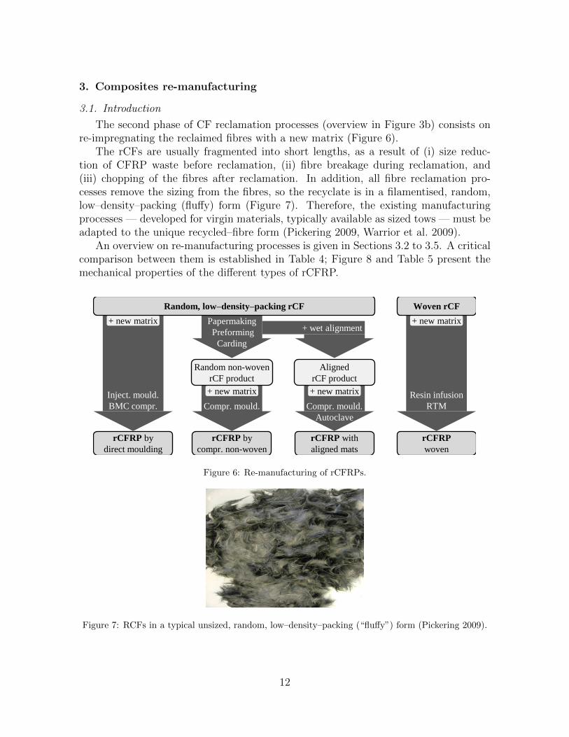
The second phase of CF reclamation processes (overview in Figure 3b) consists onre-impregnating the reclaimed fibres with a new matrix (Figure 6).
The rCFs are usually fragmented into short lengths, as a result of (i) size reduc-tion of CFRP waste before reclamation, (ii) fibre breakage during reclamation, and(iii) chopping of the fibres after reclamation. In addition, all fibre reclamation pro-cesses remove the sizing from the fibres, so the recyclate is in a filamentised, random,low–density–packing (fluffy) form (Figure 7). Therefore, the existing manufacturingprocesses — developed for virgin materials, typically available as sized tows — must beadapted to the unique recycled–fibre form (Pickering 2009, Warrior et al. 2009).
An overview on re-manufacturing processes is given in Sections 3.2 to 3.5. A criticalcomparison between them is established in Table 4; Figure 8 and Table 5 present themechanical properties of the different types of rCFRP.
+ wet alignment
rCFRP by
direct moulding
Papermaking
Preforming
Carding
rCFRP by
compr. non-woven
rCFRP with
aligned mats
rCFRP
woven
Compr. mould. Compr. mould.
Autoclave
Inject. mould.
BMC compr.
Resin infusion
RTM
+ new matrix
+ new matrix + new matrix
+ new matrix
Random non-woven
rCF product
Aligned
rCF product
Random, low–density–packing rCF Woven rCF
Figure 6: Re-manufacturing of rCFRPs.
Figure 7: RCFs in a typical unsized, random, low–density–packing (“fluffy”) form (Pickering 2009).
12
Tab
le4:
Su
mm
ary
an
aly
sis
of
diff
eren
tre
-manu
fact
uri
ng
pro
cess
es.
Pro
cess
Ad
vanta
ges
Dra
wb
ack
sIm
ple
men
tati
on
Manu
fact
ure
rM
atr
ix(?
)F
ocu
s(†)
Directmould.(see
Section3.2)◦
Pro
cess
esal
read
yes
tab
lish
ed(1
)
◦M
ech
anic
alp
erfo
rman
ceco
mp
atib
lew
ith
low
–or
med
ium
–en
dst
ruct
ura
lap
pli
cati
ons
−V
ery
low
fibre
conte
nts
(Vf<
20%
)−
Red
uce
dfi
bre
len
gth
(2)
−D
ifficu
ltp
roce
ssin
gd
ue
torC
Fs’
fila
men
tise
dfo
rm(2
)(3
)(4
)
·W
on
get
al.
(2007a)
–IM
·C
on
nor
(2008)
–IM
·P
icke
rin
get
al.
(2006),
Tu
rner
etal.
(2009),
Warr
ior
etal.
(2009)
–B
MC
(PP
)(P
C)
(EP
,VE
)
P,T T
P,T
,D
Compr.mould.ofnon-wovenproducts
(seeSection3.3)
◦P
roce
sses
requ
irin
gm
inor
adap
tati
ons
only
(5)
◦P
roce
sses
wid
ely
use
dfo
rrC
FR
Pan
dw
ell
docu
men
ted
◦M
ech
.p
rop
erti
esco
mp
arab
leto
vir
gin
stru
ctu
ral
mat
eria
ls(6
)(7
)
◦P
oten
tial
app
lica
tion
inau
tom
otiv
ean
dai
rcra
ftin
du
stri
es(8
)(9
)
−C
om
mon
fib
red
am
age
du
rin
gco
mp
ress
ion
mou
ldin
g(6
)(1
0)
−C
om
pet
ing
mark
etd
om
inate
dby
rela
tivel
ych
eap
mate
rials
(8)
·P
icke
rin
get
al.
(2006),
Tu
rner
etal.
(2009),
Won
get
al.
(2007b
,2009a)
·Jan
ney
etal.
(2009)
·N
aka
gaw
aet
al.
(2009)
·S
zpie
get
al.
(2009b
)·
Corn
acc
hia
etal.
(2009)
(EP
)
(EP
,UP
)(U
P)
(rP
P)
(PP
)
P,T
,D
P,T
,DT
,DP
,T P
Compr.mould.ofalignedmats
(seeSection3.4)
◦Im
pro
ved
un
iaxia
lm
ech
anic
alp
rop
erti
es(1
1)
◦P
ossi
bil
ity
ofta
ilor
ing
the
lay-u
pof
rCF
RP
lam
inat
es◦
Pot
enti
alfo
rp
rese
rvin
gfi
bre
len
gth
and
ach
ievin
gh
igh
erre
info
rcem
ent
frac
tion
s(2
)(1
1)
−N
eed
for
nea
rly
per
fect
ali
gn
men
tto
sign
ifica
ntl
yim
pro
vep
ack
ab
ilit
y(2
)
−N
eed
for
sub
stanti
al
dev
elop
men
tof
pro
cess
es(2
)(1
1)
·T
urn
eret
al.
(2009),
How
art
han
dJes
chke
(2009),
Won
get
al.
(2009b
)–
pap
erm
akin
gte
chn
ique
·Jan
ney
etal.
(2007)
–3-D
EP
·W
on
get
al.
(2009a)
–ce
ntr
if.
ali
gn
.ri
g·
Won
get
al.
(2009b
)–
yarn
spin
nin
g
(EP
)
(EP
,UP
)(u
n.)
(un
.)
P,T P P P
Impregnationofwoven
(seeSection3.5)
◦S
tru
ctu
red
arch
itec
ture
wit
hco
nti
nu
ous
fib
res
and
hig
hre
info
rcem
ent
conte
nt
◦S
imp
lici
tyof
man
ufa
ctu
rin
gp
roce
sses
◦A
pp
lica
ble
dem
onst
rato
rsal
read
ym
anu
fact
ure
d
−A
pp
lica
bil
ity
curr
entl
yre
du
ced
top
re-p
reg
EoL
roll
s−
Exp
erim
enta
lre
ali
sati
on
of
theo
reti
cal
mec
han
ical
pro
per
ties
stil
lto
be
mea
sure
d
·A
llen
(2008)
·M
ered
ith
(2009)
·G
eorg
e(2
009)
(EP
)(u
n.)
(un
.)
T D D
(?)
Key
for
Mat
rix:
(r)P
P:
(rec
ycl
ed)
pol
yp
ropyle
ne;
PC
:p
oly
carb
on
ate
;E
P:
epox
yre
sin
;V
E:
vin
yle
ster
resi
n;
UP
:u
nsa
tura
ted
poly
este
r;u
n.:
un
kn
own
.(†)
Key
for
Focu
s:P
:p
roce
ssd
evel
opm
ent;
T:
mec
han
ical
test
ing;
D:
dem
on
stra
tor
manu
fact
uri
ng
(see
Tab
le8).
(1)
Ast
rom
1997
;(2
)T
urn
eret
al.
2009
;(3
)C
onn
or
2008;(4
)P
icke
rin
get
al.
(2006);
(5)
Str
on
gan
dP
losk
on
ka(1
989);
(6)
Pim
enta
etal.
(2010a);
(7)
Won
get
al.
(200
7b);
(8)
Car
ber
ry(2
009)
;(9
)Jan
ney
etal.
(2009);
(10)
Won
get
al.
(2009a);
(11)
Won
get
al.
(2009b
);
13
226 sm10ρE
0
10
20
30
40
50
rCFRPs Virgin
materials
GF
RP
Alu
min
ium
2D
no
n-w
oven
3-D
EP
Ali
gned
mat
(a) Specific stiffness.
0
100
200
300
223 sm10ρX
rCFRPs Virgin
materials
GF
RP
Alu
min
ium
2D
no
n-w
oven
3-D
EP
Ali
gned
mat
(b) Specific strength.
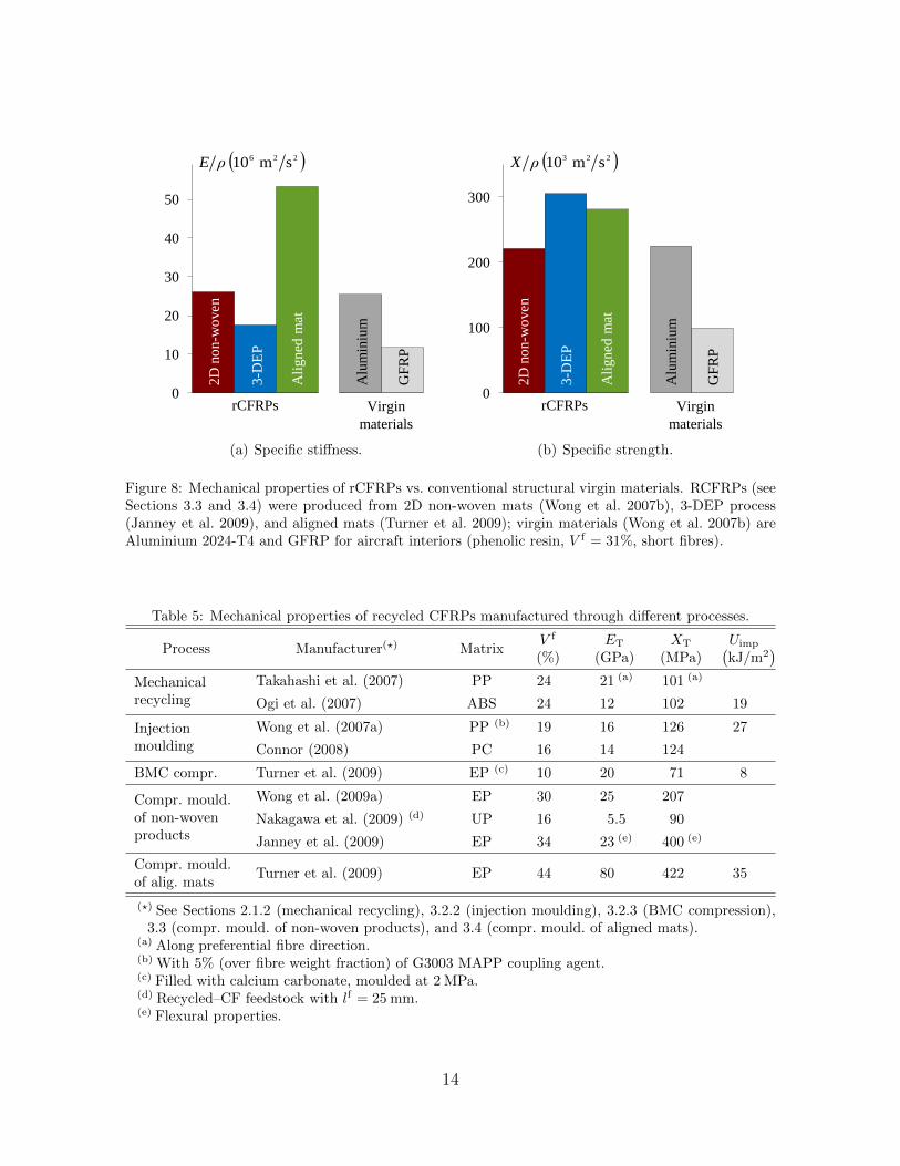
Figure 8: Mechanical properties of rCFRPs vs. conventional structural virgin materials. RCFRPs (seeSections 3.3 and 3.4) were produced from 2D non-woven mats (Wong et al. 2007b), 3-DEP process(Janney et al. 2009), and aligned mats (Turner et al. 2009); virgin materials (Wong et al. 2007b) areAluminium 2024-T4 and GFRP for aircraft interiors (phenolic resin, V f = 31%, short fibres).
Table 5: Mechanical properties of recycled CFRPs manufactured through different processes.
Process Manufacturer(?) MatrixV f
(%)ET
(GPa)XT
(MPa)Uimp(kJ/m2
)Mechanicalrecycling
Takahashi et al. (2007) PP 24 21 (a) 101 (a)
Ogi et al. (2007) ABS 24 12 102 19
Injectionmoulding
Wong et al. (2007a) PP (b) 19 16 126 27
Connor (2008) PC 16 14 124
BMC compr. Turner et al. (2009) EP (c) 10 20 71 8
Compr. mould.of non-wovenproducts
Wong et al. (2009a) EP 30 25 207
Nakagawa et al. (2009) (d) UP 16 5.5 90
Janney et al. (2009) EP 34 23 (e) 400 (e)
Compr. mould.of alig. mats
Turner et al. (2009) EP 44 80 422 35
(?) See Sections 2.1.2 (mechanical recycling), 3.2.2 (injection moulding), 3.2.3 (BMC compression),3.3 (compr. mould. of non-woven products), and 3.4 (compr. mould. of aligned mats).
(a) Along preferential fibre direction.(b) With 5% (over fibre weight fraction) of G3003 MAPP coupling agent.(c) Filled with calcium carbonate, moulded at 2 MPa.(d) Recycled–CF feedstock with lf = 25 mm.(e) Flexural properties.
14
3.2. Direct moulding
3.2.1. Overview
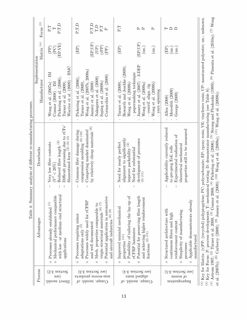
Injection moulding (IM) and bulk moulding compound (BMC) compression are twodirect methods of remoulding rCFs into recycled composites. Advantages, drawbacksand applications of these processes are summarised in Table 4, and the mechanicalproperties of the composites are presented in Table 5.
3.2.2. Injection moulding
During IM, a mixture of resin (typically a thermoplastic), rCFs (short or milled)and fillers / additives is pre-compounded into pellets, which are subsequently injectedinto a mould (at 10 MPa to 100 MPa) (Astrom 1997).
Wong et al. (2007a) injected rCFs (from FBP) with polypropylene (PP). The ad-dition of coupling agents (maleic anhydride grafted polypropylene, MAPP) improvedfibre–matrix adhesion and thus the overall mechanical properties (Table 5).
Connor (2008) manufactured and compared the performance of two injected CFRPs:one with virgin and another with recycled (from RCFL) carbon fibres. The recyclate(Table 5) was 25% less stiff than the virgin control; strength reduction was less pro-nounced (12%), likely due to an improved fibre–matrix adhesion in the recyclate. Thesame process was not successful with fibres from ATI (1994), because of their moredispersed structure and poorer fibre–matrix adhesion.
3.2.3. BMC compression
BMCs are intermediate products made by mixing resin (typically a thermoset),rCFs, fillers and curing agents into bulky charges; this premix is subsequently com-pression moulded (under 3.5 MPa to 35 MPa) into a component (Allen 2008, Astrom1997).
Pickering et al. (2006) and Turner et al. (2009) moulded several BMCs with rCFsfrom the FBP and SCFs. The formulation of the BMC was tuned so as to overcome thepoor flow properties of the resin and the filamentised and entangled form of the fibres.The main factors affecting the mechanical performance of the rCFRPs (especially thestrength) were the fractions of fillers and of rCFs. The mechanical performance ofthe rCFRPs (optimised properties in Table 5) was superior to that of commercial glassBMCs (Warrior et al. 2009); however, it is not clear whether these rCFRPs can competein price (Pickering et al. 2010).
3.3. Compression moulding of intermediate non-woven products
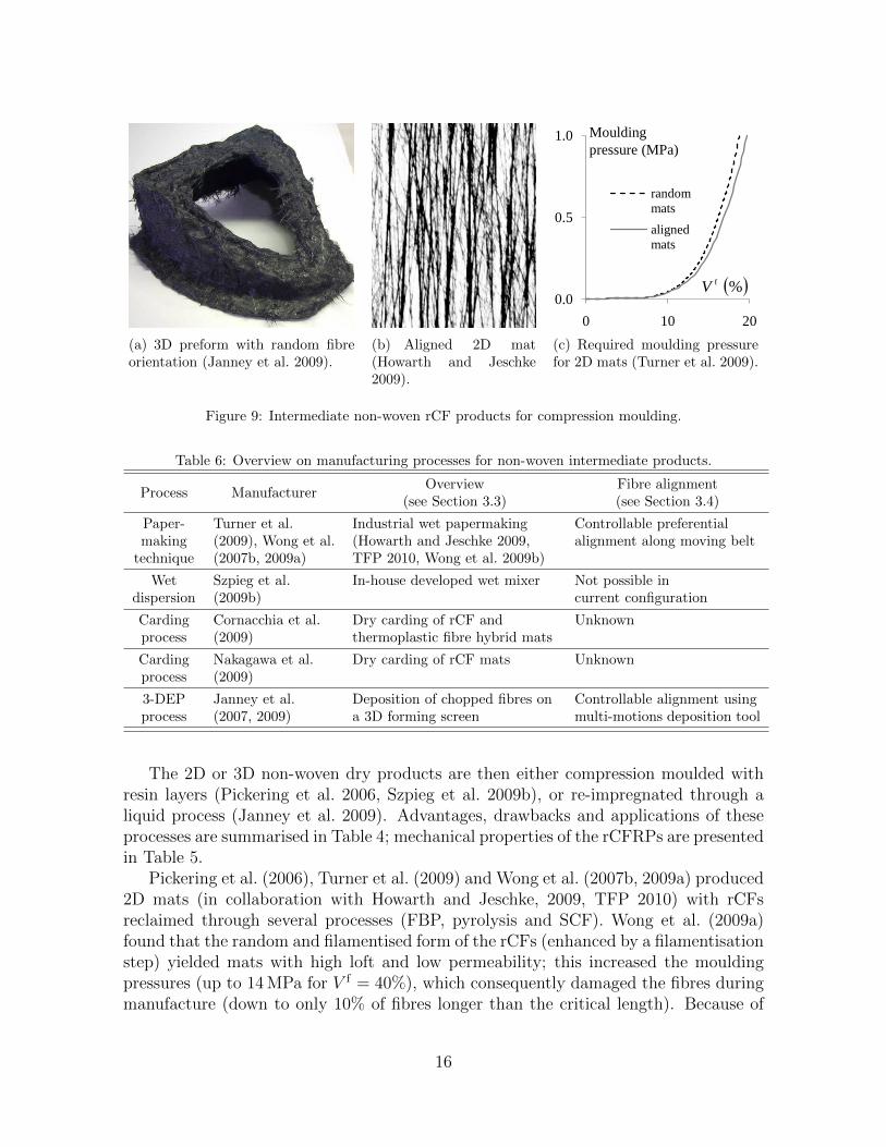
The production and subsequent re-impregnation of 2D or 3D rCF non-woven dryproducts (with a short and random reinforcement architecture, Figure 9a) is one of themost widely used manufacturing processes for rCFRPs.
Several methods to produce the intermediate dry non-woven products are sum-marised in Table 6; the potential for fibre alignment (detailed in Section 3.4) is high-lighted. Most techniques are similar to the production of Chopped Strand Mats (mostlyapplied to vGFRP, Strong and Ploskonka, 1989) or paper (TFP 2010).
15
(a) 3D preform with random fibreorientation (Janney et al. 2009).
(b) Aligned 2D mat(Howarth and Jeschke2009).
0.0
0.5
1.0
0 10 20
random
mats
aligned
mats
%fV
Moulding
pressure (MPa)
(c) Required moulding pressurefor 2D mats (Turner et al. 2009).
Figure 9: Intermediate non-woven rCF products for compression moulding.
Table 6: Overview on manufacturing processes for non-woven intermediate products.
Process ManufacturerOverview
(see Section 3.3)Fibre alignment(see Section 3.4)
Paper-making
technique
Turner et al.(2009), Wong et al.(2007b, 2009a)
Industrial wet papermaking(Howarth and Jeschke 2009,TFP 2010, Wong et al. 2009b)
Controllable preferentialalignment along moving belt
Wetdispersion
Szpieg et al.(2009b)
In-house developed wet mixer Not possible incurrent configuration
Cardingprocess
Cornacchia et al.(2009)
Dry carding of rCF andthermoplastic fibre hybrid mats
Unknown
Cardingprocess
Nakagawa et al.(2009)
Dry carding of rCF mats Unknown
3-DEPprocess
Janney et al.(2007, 2009)
Deposition of chopped fibres ona 3D forming screen
Controllable alignment usingmulti-motions deposition tool
The 2D or 3D non-woven dry products are then either compression moulded withresin layers (Pickering et al. 2006, Szpieg et al. 2009b), or re-impregnated through aliquid process (Janney et al. 2009). Advantages, drawbacks and applications of theseprocesses are summarised in Table 4; mechanical properties of the rCFRPs are presentedin Table 5.
Pickering et al. (2006), Turner et al. (2009) and Wong et al. (2007b, 2009a) produced2D mats (in collaboration with Howarth and Jeschke, 2009, TFP 2010) with rCFsreclaimed through several processes (FBP, pyrolysis and SCF). Wong et al. (2009a)found that the random and filamentised form of the rCFs (enhanced by a filamentisationstep) yielded mats with high loft and low permeability; this increased the mouldingpressures (up to 14 MPa for V f = 40%), which consequently damaged the fibres duringmanufacture (down to only 10% of fibres longer than the critical length). Because of
16
these issues, the rCFRP tensile strength saturated at V f = 30% (Wong et al. 2007b,2009a); nevertheless, fibre–matrix adhesion was good, and the specific stiffness andstrength of the optimised rCFRP compared favourably with virgin materials (Table 5and Figure 8). Current work focuses on improving the mat–flow properties (e.g. byusing thin mats down to 10 gsm, performing pre-compaction, reducing binder levels,filling the resin, Turner et al. 2009, Warrior et al. 2009), and studying alternatives tocompression moulding (e.g. autoclave and out–of–autoclave curing, Turner et al. 2009,Warrior et al. 2009).
Janney et al. (2007, 2009) developed the three dimensional engineered (3-DEP) pre-forming process, initially for virgin fibres but also applicable to recyclates; the processconsists on the deposition of chopped fibres (dispersed in water) on a porous formingscreen mounted on a deposition tool, through application of vacuum (MIT 2010). Themultiple–motions of the deposition tool enabled manufacturing of complex 3D parts(Figure 9a), with controlled fibre placement and orientation if required (detailed inSection 3.4). The researchers found that using constant fibre–lengths within each plateimproved the permeability of the preforms during compression moulding (at 1.7 MPa)and, consequently, the mechanical performance of the rCFRP (Figure 8 and Table 5).
Nakagawa et al. (2009) manufactured sheet moulding compounds (SMCs) by cardingthe rCFs. The composite’s tensile strength (Table 5) increased with the length of therCFs fed to the carding machine up to a saturation point at lf ≈ 40 mm.
Szpieg et al. (2009b) produced fully–recycled composites, with milled rCFs (suppliedby HADEG Recycling Ltd., lfavg ≈ 200 µm) and reprocessed PP PURE manufacturingscrap (Szpieg et al. 2009a). Overall fibre content was 25% < V f < 30%, but resin richregions were present; nevertheless, void content was only 1%. Giannadakis et al. (2010)studied the material’s mechanical response, including non-linear visco-elastic and plasticeffects; current work focuses on improving performance.
Cornacchia et al. (2009) manufactured hybrid non-woven mats with their in-houserecycled CFs and PP fibres, using a carding process and subsequent compression mould-ing (at 8 MPa for V f = 30%).
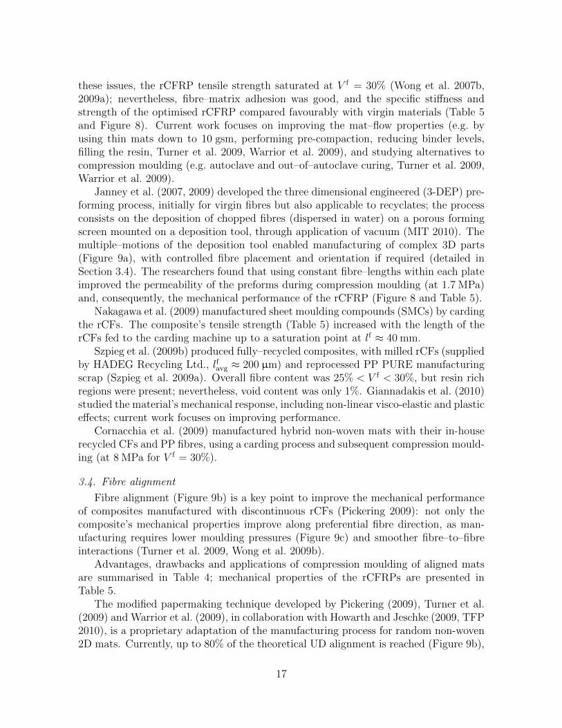
3.4. Fibre alignment
Fibre alignment (Figure 9b) is a key point to improve the mechanical performanceof composites manufactured with discontinuous rCFs (Pickering 2009): not only thecomposite’s mechanical properties improve along preferential fibre direction, as man-ufacturing requires lower moulding pressures (Figure 9c) and smoother fibre–to–fibreinteractions (Turner et al. 2009, Wong et al. 2009b).
Advantages, drawbacks and applications of compression moulding of aligned matsare summarised in Table 4; mechanical properties of the rCFRPs are presented inTable 5.
The modified papermaking technique developed by Pickering (2009), Turner et al.(2009) and Warrior et al. (2009), in collaboration with Howarth and Jeschke (2009, TFP2010), is a proprietary adaptation of the manufacturing process for random non-woven2D mats. Currently, up to 80% of the theoretical UD alignment is reached (Figure 9b),
17
using shorter rCFs and thin mats (down to 10gsm). This method yielded rCFRPs withthe highest mechanical properties ever reported (Figure 8 and Table 5); however, thefilamentised rCF form reduced the impact energy to half of that typically measuredfor GFRP SMCs (Turner et al. 2009). Ongoing work focuses on improving packabilityof mats and through–the–thickness uniformity of alignment (Turner et al. 2009, Wonget al. 2009b).
The 3-DEP process (Section 3.2) developed by Janney et al. (2007) was used toproduce a vCFRP cone with fibres preferentially aligned circunferentially; this wasachieved by adjusting the position and motion of the deposition tool.
A centrifugal alignment rig was presented by Wong et al. (2009b); it uses a rotatingdrum equipped with a convergent nozzle, which aligns a highly–dispersed suspension ofrCFs. The use of shorter fibres (down to lf ≈ 5 mm) improved the rCFRP alignmentobtained (up to 90%).
A yarn spinning technique is under development by Wong et al. (2009b), within theFibreCycle project (Marsh 2009). Wet dispersions of rCFs are transported through apipe with an induced vortex; under optimised conditions, spun yarns with 50 filamentsand 60 mm long are produced.
3.5. Woven rCFRP
As some recycling processes can preserve the reinforcement architecture of the waste(Section 2), it is possible to recover the structured weave from large woven items, e.g.out–of–date pre-preg rolls, EoL aircraft fuselage, or pre-preg trimmings from large com-ponents; re-impregnating (through e.g. resin transfer moulding (RTM) or resin infusion)the recycled weave fabrics then produces woven rCFRPs. With currently available re-cycling processes, stiffness and strength could theoretically reach more than 70GPa and700 MPa respectively; moreover, fabrics reclaimed from pre-preg rolls would be fullytraceable. Advantages, drawbacks and applications of this process are summarised inTable 4.
Allen (2008) used woven fabrics from undisclosed recyclers; the mechanical prop-erties of the rCFRPs were poor when compared to similar vCFRPs (especially tensilestrength), due to fibre degradation during recycling.
Meredith (2009) applied woven rCFRP to non–critical parts of an environmentallysustainable Formula-3 car (Figure 10c); the car also uses other recycled and naturalmaterials (e.g. potato starch) and bio-fuels (e.g. derivatives from chocolate oil).
George (2009) produced a rCFRP tool (Janicki 2010) for composite lay–up in aircraftmanufacturing.
4. Discussion
4.1. State of the art and outlook in recycling and re-manufacturing technologies
Three methods for recovering clean fibres from CFRP waste were identified: py-rolysis, oxidation in fluidised bed, and chemical recycling (Table 2). Pyrolysis is cur-rently the only process with commercial–scale implementations (JCMA 2006, MIT 2010,
18
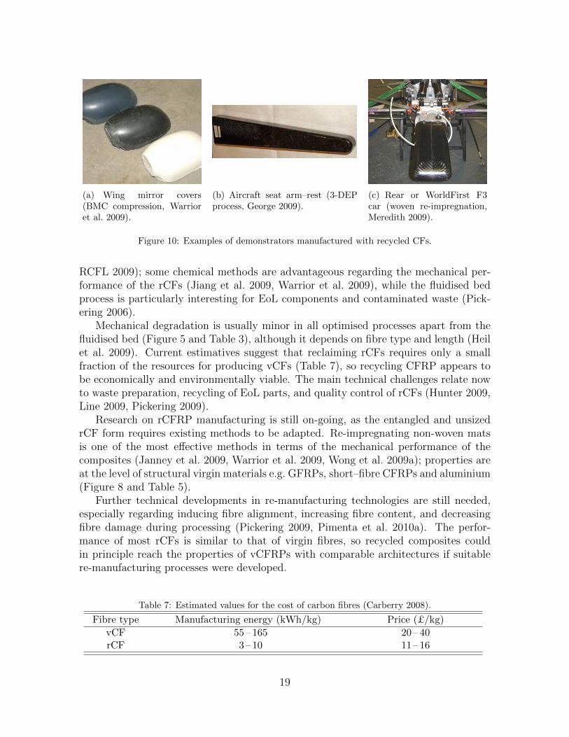
(a) Wing mirror covers(BMC compression, Warrioret al. 2009).
(b) Aircraft seat arm–rest (3-DEPprocess, George 2009).
(c) Rear or WorldFirst F3car (woven re-impregnation,Meredith 2009).
Figure 10: Examples of demonstrators manufactured with recycled CFs.
RCFL 2009); some chemical methods are advantageous regarding the mechanical per-formance of the rCFs (Jiang et al. 2009, Warrior et al. 2009), while the fluidised bedprocess is particularly interesting for EoL components and contaminated waste (Pick-ering 2006).
Mechanical degradation is usually minor in all optimised processes apart from thefluidised bed (Figure 5 and Table 3), although it depends on fibre type and length (Heilet al. 2009). Current estimatives suggest that reclaiming rCFs requires only a smallfraction of the resources for producing vCFs (Table 7), so recycling CFRP appears tobe economically and environmentally viable. The main technical challenges relate nowto waste preparation, recycling of EoL parts, and quality control of rCFs (Hunter 2009,Line 2009, Pickering 2009).
Research on rCFRP manufacturing is still on-going, as the entangled and unsizedrCF form requires existing methods to be adapted. Re-impregnating non-woven matsis one of the most effective methods in terms of the mechanical performance of thecomposites (Janney et al. 2009, Warrior et al. 2009, Wong et al. 2009a); properties areat the level of structural virgin materials e.g. GFRPs, short–fibre CFRPs and aluminium(Figure 8 and Table 5).
Further technical developments in re-manufacturing technologies are still needed,especially regarding inducing fibre alignment, increasing fibre content, and decreasingfibre damage during processing (Pickering 2009, Pimenta et al. 2010a). The perfor-mance of most rCFs is similar to that of virgin fibres, so recycled composites couldin principle reach the properties of vCFRPs with comparable architectures if suitablere-manufacturing processes were developed.
Table 7: Estimated values for the cost of carbon fibres (Carberry 2008).
Fibre type Manufacturing energy (kWh/kg) Price (£/kg)
vCF 55 – 165 20 – 40rCF 3 – 10 11 – 16
19
Table 8: Demonstrators manufactured with recycled CFs.
rCFRP
demonstrator(?)Virgin
component
CFrecycler
(see Section 2)
rCFRPmanufacturer(see Section 3)
rCFRP
matrix(†)
Wing mirrorcover
Unknown Unknown Warrior et al.(2009)
UP
Car doorpanel
Unknown Unknown Warrior et al.(2009)
EP
Corvette wheelhouse EoL F-18 aircraftstabiliser
RCFL (2009) Janney et al.(2009)
UP
Aircraft seat arm rest(George 2009)
Aircraft testing &manufact. waste
Janney et al.(2009)
Janney et al.(2009)
EP
Driver’s seat of a StudentFormula SAE car
Tennis rackets Nakagawa et al.(2009)
Nakagawa et al.(2009)
UP
Rear structure ofWorldFirst F3 green car
Outdated wovenpre-preg
RCFL (2009) Meredith (2009) EP
Tool for compositelay-up
Outdated wovenpre-preg
RCFL (2009) George (2009) un.
(?) Additional information can be found in the reference associated with the rCFRP manufacturer,unless otherwise here specified.
(†) Key for rCFRP matrix: EP: epoxy resin; UP: unsaturated polyester; un.: unknown.
A few structural components have been manufactured with rCFRPs as technologydemonstrators: crashworthy and secondary components for the automotive industry,components for aircraft interiors, and tooling (Figure 10 and Table 8).
4.2. Forthcoming challenges to the commercialisation of rCFs
In addition to the technical challenges identified in the previous section, the majorcurrent challenge to CFRP recycling operations is the establishment of a sound CFRPrecycling chain supporting the effective commercialisation of recycling processes andproducts. The main issues to overcome, as identified by academics, recyclers, end-usersand governments, are:
• Global strategy: organised networks for CFRP recycling (Table 1) — bringingtogether suppliers / users (composite–related industries), recyclers and researchers— must be created, so as to understand the current state of the art and plan forfuture developments on the topic according to industrial needs (BIS 2009).
• Incentives for recycling: governments should support the option of recycling; thiscould involve not only penalties for non-recyclers (e.g. landfilling taxes) but alsodirect privileges (e.g. carbon credits) for companies recycling their CFRP waste(Line 2009).
• Implementing suitable legislation: there is currently a void in specific legisla-tion covering the CFRP recycling operations. For instance, the classification of
20
pyrolysis processes for CFRP recycling should be distinguished from that of tra-ditional pyrolysis processes (Alsop 2009); a suitable classification of CFRP wastefor international transport to recycling units needs to be approved.
• Logistics and cooperation in the supplying chain: waste suppliers must cooperatewith recyclers, which includes supplying the waste in a continued and suitableform (Hunter 2009, Marsh 2008) and providing the recyclers with material certifi-cates whenever possible (e.g. for out-dated prepreg rolls) (Line 2009). Conversely,recyclers must ensure that materials and components supplied will not undergoreverse engineering.
• Market identification and product pricing: this requires that (i) characteristicsand properties of different rCFRPs are known, (ii) their processing times andcosts are assessed, and (iii) the value for the recycled label is established (Line2009).
• Life–cycle analysis: the environmental, economic and technical advantages ofrCFRPs over other materials and disposal methods can be estimated only throughcradle–to–grave analyses of the whole CFRP life–cycle.
• Market establishment: ultimately, the major current challenge for the successof CFRP recycling is the establishment of a market for the recyclates; this isrecognised by leading researchers (Pickering 2006, 2009), CF recyclers (Line 2009),CF users (George 2009), and analysts (McConnel 2010, Wood 2010). Creating amarket requires all the previous issues to be overcome, so rCFs are accepted asan environment–friendly and cost–effective material.
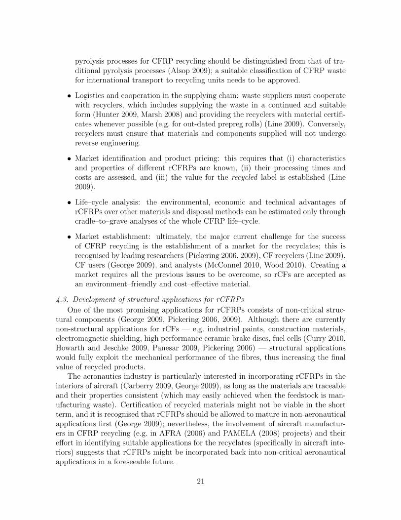
4.3. Development of structural applications for rCFRPs
One of the most promising applications for rCFRPs consists of non-critical struc-tural components (George 2009, Pickering 2006, 2009). Although there are currentlynon-structural applications for rCFs — e.g. industrial paints, construction materials,electromagnetic shielding, high performance ceramic brake discs, fuel cells (Curry 2010,Howarth and Jeschke 2009, Panesar 2009, Pickering 2006) — structural applicationswould fully exploit the mechanical performance of the fibres, thus increasing the finalvalue of recycled products.
The aeronautics industry is particularly interested in incorporating rCFRPs in theinteriors of aircraft (Carberry 2009, George 2009), as long as the materials are traceableand their properties consistent (which may easily achieved when the feedstock is man-ufacturing waste). Certification of recycled materials might not be viable in the shortterm, and it is recognised that rCFRPs should be allowed to mature in non-aeronauticalapplications first (George 2009); nevertheless, the involvement of aircraft manufactur-ers in CFRP recycling (e.g. in AFRA (2006) and PAMELA (2008) projects) and theireffort in identifying suitable applications for the recyclates (specifically in aircraft inte-riors) suggests that rCFRPs might be incorporated back into non-critical aeronauticalapplications in a foreseeable future.
21
There is also scope to manufacture automotive components with rCFRPs, not onlyfor technical or economic reasons, but also to boost green credentials. As legislationtightened regarding recyclability and sustainability (EU 2000/53/EC 2000), the auto-motive industry grew interest for natural composites (Ellison and McNaught 2000),which are nowadays widely used in mass production despite some associated problems(e.g. consistency of feedstock); rCFRPs could follow as an environmental–friendly ma-terial with improved mechanical performance.
Currently, structural demonstrators manufactured with rCFRPs are aimed at air-craft or automotive industries (Figure 10, Table 8); other markets have also been iden-tified, such as construction industry, sports and household goods, and wind turbines(Pickering 2006, Pickering et al. 2010). Table 9 provides a comprehensive overviewof potential applications for several types of rCFRPs; this is complemented by spe-cific applications currently manufactured with virgin materials, to allow for a directcomparison regarding manufacturing methods and mechanical properties.
4.4. Multiscale analysis of the mechanical response of rCFRPs
General studies on the mechanical behaviour of rCFRPs (Connor 2008, Giannadakiset al. 2010, Janney et al. 2009, Nakagawa et al. 2009, Turner et al. 2009, Wong et al.2009a) are valuable to validate the recycling processes and to identify major weaknessesin the recyclates. They also reveal how complex and unique the architecture of rCFRPscan be, and how essential it is to investigate their mechanical response in-depth (Gibson2010, Pickering 2009).
Understanding the relations between microstructure, mechanical properties anddamage mechanisms of rCFRPs provides informed guidance for reclaimers and manu-facturers towards recyclates with optimal structural performance. Moreover, this un-derstanding supports design methods for rCFRPs, which are essential for the estab-lishment of a structural applications market. Given the urgency in closing the loop onthe CFRP life–cycle, analysing the mechanical response of rCFRPs at the micro andmacromechanical levels has become critical for the continued use of composites.
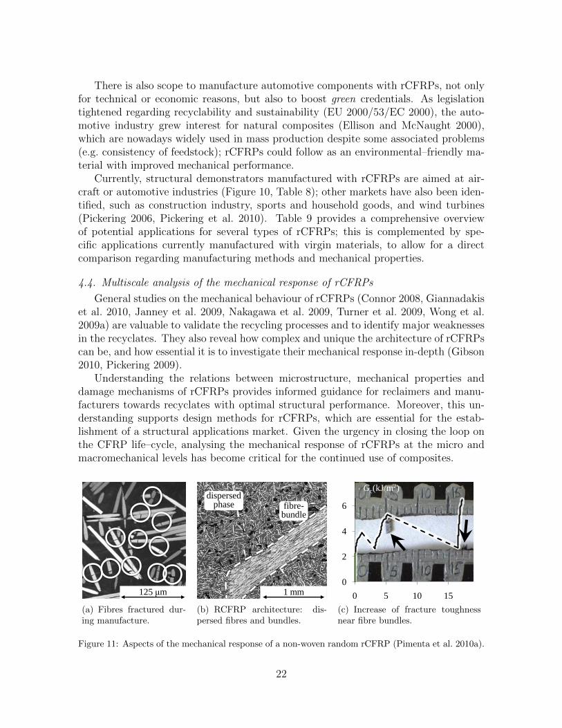
125 μm
(a) Fibres fractured dur-ing manufacture.
1 mm
fibre-bundle
dispersed phase
(b) RCFRP architecture: dis-persed fibres and bundles.
0
2
4
6
0 5 10 15
Gc(kJ/m2)
(c) Increase of fracture toughnessnear fibre bundles.
Figure 11: Aspects of the mechanical response of a non-woven random rCFRP (Pimenta et al. 2010a).
22
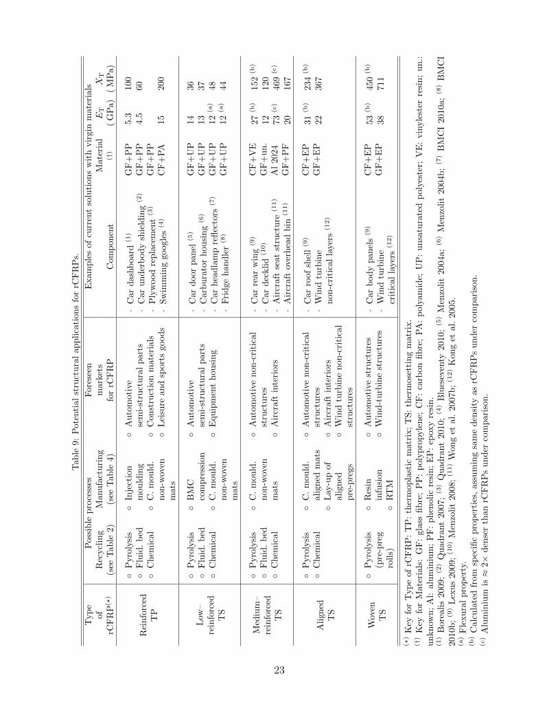
Tab
le9:
Pote
nti
al
stru
ctu
ral
ap
pli
cati
on
sfo
rrC
FR
Ps.
Typ
eof
rCF
RP(?
)
Pos
sib
lep
roce
sses
Fore
seen
mark
ets
for
rCF
RP
Exam
ple
sof
curr
ent
solu
tion
sw
ith
vir
gin
mate
rials
Rec
ycl
ing
(see
Tab
le2)
Man
ufa
ctu
rin
g(s
eeT
able
4)
Com
pon
ent
Mate
rial
(†)
ET
(G
Pa)
XT
(M
Pa)
Rei
nfo
rced
TP
◦P
yro
lysi
s◦
Flu
id.
bed
◦C
hem
ical
◦In
ject
ion
mou
ldin
g◦
C.
mou
ld.
non
-wov
enm
ats
◦A
uto
moti
vese
mi-
stru
ctu
ral
part
s◦
Con
stru
ctio
nm
ate
rials
◦L
eisu
rean
dsp
ort
sgood
s
·C
ar
dash
board
(1)
·C
ar
un
der
bod
ysh
ield
ing
(2)
·P
lyw
ood
rep
lace
men
t(3
)
·S
wim
min
ggoogle
s(4
)
GF
+P
PG
F+
PP
GF
+P
PC
F+
PA
5.3
4.5
15
100
60
200
Low
–re
info
rced
TS
◦P
yro
lysi
s◦
Flu
id.
bed
◦C
hem
ical
◦B
MC
com
pre
ssio
n◦
C.
mou
ld.
non
-wov
enm
ats
◦A
uto
moti
vese
mi-
stru
ctu
ral
part
s◦
Equ
ipm
ent
hou
sin
g
·C
ar
door
pan
el(5
)
·C
arb
ura
tor
hou
sin
g(6
)
·C
ar
hea
dla
mp
refl
ecto
rs(7
)
·F
rid
ge
han
dle
r(8
)
GF
+U
PG
F+
UP
GF
+U
PG
F+
UP
14
13
12
(a)
12
(a)
36
37
48
44
Med
ium
–re
info
rced
TS
◦P
yro
lysi
s◦
Flu
id.
bed
◦C
hem
ical
◦C
.m
ould
.n
on-w
oven
mat
s
◦A
uto
moti
ven
on-c
riti
cal
stru
ctu
res
◦A
ircr
aft
inte
riors
·C
ar
rear
win
g(9
)
·C
ar
dec
kli
d(1
0)
·A
ircr
aft
seat
stru
ctu
re(1
1)
·A
ircr
aft
over
hea
db
in(1
1)
CF
+V
EG
F+
un
.A
l2024
GF
+P
F
27
(b)
12
73
(c)
20
152
(b)
120
469
(c)
167
Ali
gned
TS
◦P
yro
lysi
s◦
Ch
emic
al◦
C.
mou
ld.
alig
ned
mats
◦L
ay-u
pof
alig
ned
pre
-pre
gs
◦A
uto
moti
ven
on-c
riti
cal
stru
ctu
res
◦A
ircr
aft
inte
riors
◦W
ind
turb
ine
non
-cri
tica
lst
ruct
ure
s
·C
ar
roof
shel
l(9
)
·W
ind
turb
ine
non
-cri
tica
lla
yers
(12)
CF
+E
PG
F+
EP
31
(b)
22
234
(b)
367
Wov
enT
S
◦P
yro
lysi
s(p
re-p
reg
roll
s)
◦R
esin
infu
sion
◦R
TM
◦A
uto
moti
vest
ruct
ure
s◦
Win
d-t
urb
ine
stru
ctu
res
·C
ar
bod
yp
an
els
(9)
·W
ind
turb
ine
crit
ical
laye
rs(1
2)
CF
+E
PG
F+
EP
53
(b)
38
450
(b)
711
(?)
Key
for
Typ
eof
rCF
RP
:T
P:
ther
mop
last
icm
atr
ix;
TS
:th
erm
ose
ttin
gm
atr
ix.
(†)
Key
for
Mat
eria
ls:
GF
:gl
ass
fib
re;
PP
:p
olyp
ropyle
ne;
CF
:ca
rbon
fib
re;
PA
:p
oly
am
ide;
UP
:u
nsa
tura
ted
poly
este
r;V
E:
vin
yle
ster
resi
n;
un.:
un
kn
own
;A
l:al
um
iniu
m;
PF
:p
hen
olic
resi
n;
EP
:ep
oxy
resi
n.
(1)
Bor
eali
s20
09;(2
)Q
uad
rant
2007
;(3
)Q
uad
rant
2010;(4
)B
lues
even
ty2010;(5
)M
enzo
lit
2004a;(6
)M
enzo
lit
2004b
;(7
)B
MC
I2010a;(8
)B
MC
I20
10b
;(9
)L
exu
s20
09;(1
0)
Men
zoli
t20
08;(1
1)
Won
get
al.
2007b
;(1
2)
Kon
get
al.
2005.
(a)
Fle
xu
ral
pro
per
ty.
(b)
Cal
cula
ted
from
spec
ific
pro
per
ties
,as
sum
ing
sam
ed
ensi
tyas
rCF
RP
su
nd
erco
mp
ari
son
.(c)
Alu
min
ium
is≈
2×d
ense
rth
anrC
FR
Ps
un
der
com
pari
son
.
23
A detailed multiscale mechanical study of a state–of–the–art rCFRP (manufacturedat the University of Nottingham with fibres reclaimed at RCFL) was performed at Im-perial College London (Pimenta et al. 2010a); microstructure, mechanical properties,and failure and toughening mechanisms were investigated, and the influence of recy-cling and re-manufacturing processes analysed. The study showed that the extensivebreakage of fibres during re-manufacturing lead to a considerable degradation of tensilestrength at the composite level (Figure 11a); in addition, it was found that fibre bundles— held together by minimal amounts of residual matrix not completely pyrolysed —increase the in-plane fracture toughness of the material (Figures 11b and 11c).
The work by Pimenta et al. (2010a) proved that a feature usually seen as a recyclingdefect — incomplete removal of matrix — can actually enhance the mechanical responseof the recyclates, which illustrates the need for a comprehensive approach towards theoptimisation of processes. In addition, the experimental observations were used todevelop multiscale analytical models to predict the properties of recycled composites(Pimenta et al. 2010b), which can be used in the design of rCFRP structural compo-nents. As recycling and re-manufacturing processes evolve, other types of rCFRPs canbe analysed in a similar framework.
5. Conclusions
A comprehensive overview on the state of the art and market outlook for CFRPrecycling operations was presented; recycling and re-manufacturing processes were re-viewed, and the commercialisation challenges and potential markets for the recyclateswere identified.
A critical comparison between recycling processes proved each of them to have spe-cific advantages and drawbacks, suggesting complementarity rather than competition.Most of recycling processes yield rCFs with high retention of mechanical properties,and a few commercial–scale plants already exist (Tables 2 and 3).
Re-manufacturing composites with rCFs was found to be challenging, especiallyregarding achieving high mechanical properties; research is therefore still on-going.Nevertheless, the mechanical performance of some rCFRPs overcomes that of someconventional structural materials, and a few structural demonstrators for the automo-tive and aircraft industries have been manufactured (Tables 4 to 6 and 8).
It has been shown that establishing applications for the recyclates is the key tofinally close the loop in the CFRP life–cycle. The technical feasibility of re-introducingthe recyclates in the non-critical structural market has been demonstrated, and spe-cific potential applications have been suggested (Table 9). Nevertheless, there are stillseveral non-technical issues which need to be overcome; in that sense, collaborativeorganisations focusing on the whole chain of CFRP recycling are essential (BIS 2009).
Researchwise, more detailed, multiscale and systematic studies on the mechanicalperformance of rCFs and rCFRPs are needed, so as to increase the acceptance of recy-clates as structural materials by engineers and designers. It is also essential to perform
24
life–cycle analyses of the several recycling and re-manufacturing methods, to assess costeffectiveness and environmental impact of using rCFs.
Acknowledgments
The funding from the Portuguese Foundation for Science and Technology (projectnr. SFRH/BD/44051/2008) is gratefully acknowledged.
The authors gratefully acknowledge Prof. S. J. Pickering (from the University ofNottingham), Mr. S. Line, Mr. S. Alsop and Mr. S. Johnson (from Recycled CarbonFibre Ltd., UK), and Mr. P. George and Mr. W.Carberry (from The Boeing Company)for many helpful discussions.
References
AFRA, 2006. Aircraft Fleet Recycling Association. Official website at www.
afraassociation.org (last accessed July 2010) .
AFRA, 2009. Best Management Practice for Management of Used Aircraft Partsand Assemblies. AFRA Board, available online at www.afraassociation.org/
AFRAPartsBMPv2_2.pdf.
Allen, B.E., 2008. Characterization of Reclaimed Carbon Fibers and their Integrationinto New Thermoset Polymer Matrices via Existing Composite Fabrication Tech-niques. Master Thesis. North Carolina State University, Raleigh, NC, USA.
Allred, R.E., Gosau, J.M., Shoemaker, J.M., 2001. Recycling process for carbon/epoxycomposites, in: SAMPE 2001 Symposium & Exhibition, SAMPE, Longbeach, CA,USA.
Alsop, S.H., 2009. Pyrolysis off–gas processing, in: SAMPE’09 Conference, SAMPE,Baltimore, MD, USA.
Astrom, B.T., 1997. Manufacturing of Polymer Composites. Chapman & Hall, UK.
ATI, 1994. Adherent Technologies, Inc. Official website at www.adherenttech.com
(last accessed July 2010) .
BIS, 2009. The UK Composites Strategy. Department for Business, Innovation &Skills, available online at interactive.bis.gov.uk/advancedmanufacturing (lastaccessed July 2010) .
Blueseventy, 2010. Carbon race googles. Blueseventy, available online atwww.blueseventy.com/products/detail/carbon_race, Blueseventy (last accessedJuly) .
25
BMCI, 2010a. BMC 304 Data Sheet. Bulk Molding Componds Inc., available onlineat www.bulkmolding.com/datasheets/informational/BMC_304.pdf (last accessedJuly 2010) .
BMCI, 2010b. BMC 310 Data Sheet. Bulk Molding Componds Inc., available onlineat www.bulkmolding.com/datasheets/informational/BMC_310.pdf (last accessedJuly 2010) .
Borealis, 2009. Case study: BMW 7 Series dashboard carrier. Borealis Group,available online at www.borealisgroup.com/pdf/literature/borealis-borouge/
case-study/MY_CAST097_GB_2010_02_BB.pdf (last accessed July 2010) .
Buggy, M., Farragher, L., Madden, W., 1995. Recycling of composite materials. J.Mater. Process. Technol. 55, 448–456.
Carberry, W., 2008. Airplane Recycling Efforts Benefit Boeing Operators. BoeingAERO Magazine QRT 4.08, 6–13.
Carberry, W., 2009. Aerospace’s role in the development of the recycled carbon fibresupply chain, in: Carbon Fibre Recycling and Reuse 2009 Conference, IntertechPira,Hamburg, Germany.
CFK, 2007. CFK Valley Stade Recycking GmbH & Co. KG. Official website at www.
cfk-recycling.com (last accessed July 2010) .
CFRRC, 2009. Carbon Fibre Recycling and Reuse Conference. Official website atwww.cfrecycling.com (last accessed July 2010) .
Connor, M.L., 2008. Characterization of Recycled Carbon Fibers and Their Forma-tion of Composites Using Injection Molding. Master Thesis. North Carolina StateUniversity, Raleigh, NC, USA.
Conroy, A., Halliwell, S., Reynolds, T., 2006. Composite recycling in the constructionindustry. Composites Part A 37, 1216–1222.
Cornacchia, G., Galvagno, S., Portofino, S., Caretto, F., Giovanni, Casciaro, Matera,D., Donatelli, A., Iovane, P., Martino, M., Civita, R., Coriana, S., 2009. Carbonfiber recovery from waste composites: an integrated approach for a commerciallysuccessful recycling operation, in: SAMPE’09 Conference, SAMPE, Baltimore, MD,USA.
Cunliffe, A.M., Jones, N., Williams, P.T., 2003. Pyrolysis of composite plastic waste.Environ. Technol. 24, 653–663.
Curry, R., 2010. Successful research programme allows high performance brake discsto be manufactured at lower cost. Press Release Log (January), 1–2.
26
DeRosa, R., Telfeyan, E., Mayes, J.S., 2005. Current state of recycling sheet moldingcompounds and related materials. J. Thermoplast. Compos. Mater. 18, 219–240.
Eckert, C.A., Knutson, B.L., Debenedetti, P.G., 1996. Supercritical fluids as solventsfor chemical and materials processing. Nature 383, 313–318.
ECRC, 2003. ECRC Services Company. Official website at www.ecrc-greenlabel.org(last accessed January 2010) .
Ellison, G.C., McNaught, R., 2000. The use of natural fibres in nonwoven structures forapplications as automotive component substrates. Research & Development ReportNF0309. Ministry of Agriculture, Fisheries and Food, UK.
EU 1999/31/EC, 1999. Council Directive 1999/31/EC of 26 April 1999 on the landfillof waste. The Council of the European Union, Official Journal of the EuropeanCommunities L 182–42, 1–19.
EU 2000/53/EC, 2000. Directive 2000/53/EC of the European Parliament and of theCouncil of 18 September 2000 on end-of-life vehicles. The Council of the EuropeanUnion, Official Journal of the European Communities L 269–43, 34–42.
GCF, 2010. Green Carbon Fibre. Official website at www.greencarbonfibre.com (lastaccessed July 2010) .
George, P.E., 2009. End user perspective: Perspective on carbon fibre recycling from amajor end user, in: Carbon Fibre Recycling and Reuse 2009 Conference, Intertech-Pira, Hamburg, Germany.
Giannadakis, K., Szpieg, M., Varna, J., 2010. Mechanical Performance of a RecycledCarbon Fibre/PP Composite. Exp. Mech. DOI: 10.1007/s11340-010-9369-8.
Gibson, R.F., 2010. A review of recent research on mechanics of multifunctional com-posite materials and structures. Compos. Struct. 92, 2793–2810.
Gosau, J.M., Wesley, T.F., Allred, R.E., 2009a. Carbon fiber reclamation from state-of-the-art 2nd generation aircraft composites, in: SAMPE’09 Conference, SAMPE,Baltimore, MD, USA.
Gosau, J.M., Wesley, T.F., Allred, R.E., 2009b. Recovering carbon fibre and more fromscrap composite material, in: Carbon Fibre Recycling and Reuse 2009 Conference,IntertechPira, Hamburg, Germany.
Goto, M., 2009. Chemical recycling of plastics using sub- and supercritical fluids. J.Supercrit. Fluids 47, 500–507.
HADEG, 1995. HADEG Recycling GmbH. Official website at www.hadeg-recycling.de (last accessed July 2010) .
27
Heil, J.P., Hall, M.J., Litzenberger, D.R., Clearfield, R., Cuomo, J.J., George, P.E.,Carberry, W.L., 2009. A comparison of chemical, morphological and mechanicalproperties of various recycled carbon fibers, in: SAMPE’09 Conference, SAMPE,Baltimore, MD, USA.
Hitachi, 2010. Hitachi Chemical Co., Ltd. Official website at www.hitachi-chem.co.jp(last published July 2010) .
Howarth, J., Jeschke, M., 2009. Advanced non-woven materials from recycled carbonfibre, in: Carbon Fibre Recycling and Reuse 2009 Conference, IntertechPira, Ham-burg, Germany.
Hunter, T., 2009. A recycler’s perspective on recycling carbon fibre prepreg produc-tion scrap, in: Carbon Fibre Recycling and Reuse 2009 Conference, IntertechPira,Hamburg, Germany.
Hyde, J.R., Lester, E., Kingman, S., Pickering, S., Wong, K.H., 2006. Supercriticalpropanol, a possible route to composite carbon fibre recovery: A viability study.Composites Part A 37, 2171–2175.
Janicki, 2010. Janicki Industries, Inc. Official website at www.janicki.com (last ac-cessed July 2010) .
Janney, M., Jr., E.G., Baitcher, N., 2007. Fabrication of Chopped Fiber Preformsby the 3-DEP Process, in: Composites and Polycon 2007, American CompositesManufactureres Association, Tampa, Florida, USA.
Janney, M.A., Newell, W.L., Geiger, E., Baitcher, N., Gunder, T., 2009. Manufacturingcomplex geometry composites with recycled carbon fiber, in: SAMPE’09 Conference,SAMPE, Baltimore, MD, USA.
JCMA, 2006. The Japan Carbon Fiber Manufacturers Association. Official website atwww.carbonfiber.gr.jp (last accessed July 2010) .
Jiang, G., Pickering, S.J., Lester, E.H., Turner, T.A., Wong, K.H., Warrior, N.A., 2009.Characterisation of carbon fibres recycled from carbon fibre/epoxy resin compositesusing supercritical n-propanol. Compos. Sci. and Technol. 69, 192–198.
Jiang, G., Pickering, S.J., Walker, G.S., Bowering, N., Wong, K.H., Rudd, C.D.,2007. Soft ionisation analysis of evolved gas for oxidative decomposition of an epoxyresin/carbon fibre composite. Thermochim. Acta 454, 109–115.
Jiang, G., Pickering, S.J., Walker, G.S., Wong, K.H., Rudd, C.D., 2008. Surface charac-terisation of carbon fibre recycled using fluidised bed. Appl. Surf. Sci. 254, 2588–2593.
Jody, B.J., Pomykala, J.A., Daniels, E.J., Greminger, J.L., 2004. A process to recovercarbon fibers from polymer-matrix composites in end-of-life vehicles. JOM 56, 43–47.
28
Karborek, 1999. Karborek S.p.a. Official website at www.karborek.it/fibra (lastaccessed July 2010) .
Kennerley, J.R., Kelly, R.M., Fenwick, N.J., Pickering, S.J., Rudd, C.D., 1998. Thecharacterisation and reuse of glass fibres recycled from scrap composites by the actionof a fluidised bed process. Composites Part A 29, 839–845.
Kong, C., Bang, J., Sugiyama, Y., 2005. Structural investigation of composite windturbine blade considering various load cases and fatigue life. Energy 30, 2101–2114.
Kouparitsas, C.E., Kartalis, C.N., Varelidis, P.C., Tsenoglou, C.J., Papaspyrides, C.D.,2002. Recycling of the fibrous fraction of reinforced thermoset composites. Polym.Compos. 23, 682–689.
Larsen, K., 2009. Recycling wind. Reinforced Plastics 53, 20–23,25.
Lester, E., Kingman, S., Wong, K.H., Rudd, C., Pickering, S., Hilal, N., 2004. Mi-crowave heating as a means for carbon fibre recovery from polymer composites: atechnical feasibility study. Mater. Res. Bull. 39, 1549–1556.
Lexus, 2009. Lexus LFA Press Information 2009. Toyota (GB) PLC - Lexus Division,available online at www.toyota.co.jp/en (last accessed July 2010) .
Line, S., 2009. Commercialisation of the carbon fibre recycling process, in: CarbonFibre Recycling and Reuse 2009 Conference, IntertechPira, Hamburg, Germany.
Liu, Y.Y., Meng, L.H., Huang, Y.D., Du, J.J., 2004. Recycling of carbon/epoxy com-posites. J. Appl. Polym. Sci. 94, 1912–1916.
Liu, Y.Y., Shan, G.H., Meng, L.H., 2009. Recycling of carbon fibre reinforced compos-ites using water in subcritical conditions. Mater. Sci. Eng., A 520, 179–183.
Marsh, G., 2005. Recycling collaborative combats legislation threat. Reinforced Plastics49, 24–28.
Marsh, G., 2008. Reclaiming value from post-use carbon composite. Reinforced Plastics52, 36–39.
Marsh, G., 2009. Carbon recycling: a soluble problem. Reinforced Plastics 53, 22–23,25–27.
McConnel, V.P., 2010. Launching the carbon fibre recycling industry. ReinforcedPlastics 54, 33–37.
Menzolit, 2004a. Menzolit BMC 0400 Data Sheet. Available online at www.menzolit.com/templates/rhuk_solarflare_ii/pdf/list_bmc/BMC_0400.pdf, MenzolitGmbH. (last accessed July 2010) .
29
Menzolit, 2004b. Menzolit BMC 1400 Data Sheet. Available online at www.menzolit.com/templates/rhuk_solarflare_ii/pdf/list_bmc/BMC_1400.pdf, MenzolitGmbH. (last accessed July 2010) .
Menzolit, 2008. Menzolit SMC 1800 Data Sheet. Available online at www.menzolit.
com/templates/rhuk_solarflare_ii/pdf/list_smc/SMC_1800.pdf, MenzolitGmbH. (last accessed July 2010) .
Meredith, J., 2009. The role of recycled carbon fibre composites in motorsport ap-plications, in: Carbon Fibre Recycling and Reuse 2009 Conference, IntertechPira,Hamburg, Germany.
Meyer, L.O., Schulte, K., Grove-Nielsen, E., 2007. Optimisation of a pyrolysis processfor recycling of CFRP’s, in: ICCM-16, Japan Society for Composite Materials, Kyoto,Japan.
Meyer, L.O., Schulte, K., Grove-Nielsen, E., 2009. CFRP-recycling following a pyrolysisroute: Process optimization and potentials. J. Compos. Mater. 43, 1121–1132.
MIT, 2010. Materials Innovation Technologies, LLC. Official website at www.
emergingmit.com (last accessed July 2010) .
Nakagawa, M., Shibata, K., Kuriya, H., 2009. Characterization of CFRP Using Re-covered Carbon Fibers from Waste CFRP, in: Second International Symposium onFiber Recycling, The Fiber Recycling 2009 Organizing Committee, Atlanta, Georgia,USA.
NASA, 1991. F-18 HARV in flight. Available online at www1.dfrc.nasa.gov/Gallery/Photo/F-18HARV/Small/EC91-495-15.jpg (last accessed July 2010) .
Ogi, K., Nishikawa, T., Okano, Y., Taketa, I., 2007. Mechanical properties of ABS resinreinforced with recycled CFRP. Adv. Compos. Mater. 16, 181–194.
Palmer, J., Ghita, O.R., Savage, L., Evans, K.E., 2009. Successful closed-loop recyclingof thermoset composites. Composites Part A 40, 490–498.
PAMELA, 2005. PAMELA Project. Official website at www.pamelalife.com (lastaccessed July 2010) .
PAMELA, 2008. PAMELA-Life: Main results of the project. Airbus S.A.S., avail-able online at www.pamelalife.com/english/results/PAMELA-Life-project_
results-Nov08.pdf.
Panesar, S., 2009. Converting Composite Waste Into High Quality Reusable CarbonFibre, in: JEC Composites Show, JEC Composites, Paris, France.
Pickering, S.J., 2006. Recycling technologies for thermoset composite materials —current status. Composites Part A 37, 1206–1215.
30
Pickering, S.J., 2009. Carbon fibre recycling technologies: what goes in and whatcomes out?, in: Carbon Fibre Recycling and Reuse 2009 Conference, IntertechPira,Hamburg, Germany.
Pickering, S.J., Kelly, R.M., Kennerley, J.R., Rudd, C.D., Fenwick, N.J., 2000. Afluidised-bed process for the recovery of glass fibres from scrap thermoset composites.Compos. Sci. Technol. 60, 509–523.
Pickering, S.J., Robinson, P., Pimenta, S., Pinho, S.T., 2010. Applications for recycledcarbon fibre, in: meeting of the Increasing Sustainability and Recycling Consortium(10 June 2010), BIS — UK Composites Strategy, London, UK.
Pickering, S.J., Turner, T.A., Warrior, N.A., 2006. Moulding compound developmentusing recycled carbon fibres, in: SAMPE Fall Technical Conference, SAMPE, Dallas,USA.
Pimenta, S., Pinho, S.T., Robinson, P., 2010b. Closing the loop: mechanical analysisand modelling of a multiscale recycled composite, in: ECCM-14, European Societyof Composite Materials, Budapest, Hungary.
Pimenta, S., Pinho, S.T., Robinson, P., Wong, K.H., Pickering, S.J., 2010a. Mechanicalanalysis and toughening mechanisms of a multiphase recycled CFRP. Compos. Sci.Technol. 70, 1713–1725.
Pinero-Hernanz, R., Dodds, C., Hyde, J., Garcia-Serna, J., Poliakoff, M., Lester, E.,Cocero, M.J., Kingman, S., Pickering, S., Wong, K.H., 2008a. Chemical recycling ofcarbon fibre reinforced composites in nearcritical and supercritical water. CompositesPart A 39, 454–461.
Pinero-Hernanz, R., Garcia-Serna, J., Dodds, C., Hyde, J., Poliakoff, M., Cocero, M.J.,Kingman, S., Pickering, S., Lester, E., 2008b. Chemical recycling of carbon fibrecomposites using alcohols under subcritical and supercritical conditions. J. Supercrit.Fluids 46, 83–92.
Quadrant, 2007. C100F23-F1 Product Data Sheet. Quadrant Plastic Composites Inc.,available online at www.quadrantcomposites.com/files/cms1/DS_D100F23-F1.
pdf (last accessed July 2010) .
Quadrant, 2010. Applications for Building and Construction. Quadrant Plastic Com-posites Inc., available online atwww.quadrantcomposites.com/English/page_14.aspx (last accessed July 2010) .
RCFL, 2009. Recycled Carbon Fibre Ltd. Official website at www.
recycledcarbonfibre.com (last accessed July 2010) .
Roberts, A., 2007. Rapid growth forecast for carbon fibre market. Reinforced Plastics51, 10–13.
31
Roberts, A., 2009. The Carbon Fibre Industry Worldwide 2008–2014. Materials Tech-nologies Publications, UK.
Sloan, J., 2008. Carbon Fiber 2007 looks forward with optimism. High PerformanceComposites Carbon Fiber 2007 Conference coverage, (Washington, DC, USA), Com-posites World, 5–7 December 2007.
Strong, A.B., Ploskonka, C.A., 1989. Fundamentals of Composites Manufacturing:materials, methods and applications. Society of Manufacturing Engineers, USA.
Szpieg, M., Wysocki, M., Asp, L.E., 2009a. Recycled polypropylene aimed as compositesprecursor material. Plast. Rubber Compos. 38, 412–418.
Szpieg, M., Wysocki, M., Asp, L.E., 2009b. Reuse of polymer materials and carbonfibres in novel engineering composite materials. Plast. Rubber Compos. 38, 419–425.
Takahashi, J., Matsutsuka, N., Okazumi, T., Uzawa, K., Ohsawa, I., Yamaguchi, K.,Kitano, A., 2007. Mechanical properties of recycled CFRP by injection moldingmethod, in: ICCM-16, Japan Society for Composite Materials, Kyoto, Japan.
Tarmac, 2010. Tarmac Aerosave S.A.S. Official website at www.tarmacaerosave.aero(last accessed July 2010) .
TFP, 2010. Technical Fibre Products Ltd. Official website at www.techfibres.com
(last accessed July 2010) .
Turner, T.A., Pickering, S.J., Warrior, N.A., 2009. Development of high value compositematerials using recycled carbon fibre, in: SAMPE’09 Conference, SAMPE, Baltimore,MD, USA.
Warrior, N.A., Turner, T.A., Pickering, S.J., 2009. AFRECAR and HIRECAR Projectresults, in: Carbon Fibre Recycling and Reuse 2009 Conference, IntertechPira, Ham-burg, Germany.
Wong, K.H., Pickering, S.J., Brooks, R., 2007a. Recycled Carbon Fibre ReinforcedPolypropylene Composites: Effect of Coupling Agents on Mechanical Properties, in:Composites Innovation 2007 — Improved Sustainability and Environmental Perfor-mance, NetComposites, Barcelona, Spain.
Wong, K.H., Pickering, S.J., Turner, T.A., Warrior, N.A., 2007b. Preliminary Feasi-bility Study of Reinforcing Potential of Recycled Carbon Fibre for Flame-retardantGrade Epoxy Composite, in: Composites Innovation 2007 — Improved Sustainabilityand Environmental Performance, NetComposites, Barcelona, Spain.
Wong, K.H., Pickering, S.J., Turner, T.A., Warrior, N.A., 2009a. Compression mould-ing of a recycled carbon fibre reinforced epoxy composite, in: SAMPE’09 Conference,SAMPE, Baltimore, MD, USA.
32
Wong, K.H., Turner, T.A., Pickering, S.J., Warrior, N.A., 2009b. The Potential forFibre Alignment in the Manufacture of Polymer Composites from Recycled Car-bon Fibre, in: SAE AeroTech Congress and Exhibition, SAE International, Seattle,Washington, USA.
Wood, K., 2010. Carbon fiber reclamation: Going commercial. High-PerformanceComposites 3, 1–2.
Yip, H.L.H., Pickering, S.J., Rudd, C.D., 2002. Characterisation of carbon fibres recy-cled from scrap composites using fluidised bed process. Plast. Rubber Compos. 31,278–282.
33