Embed Size (px)
Citation preview

Pub. 42004-438L
GAI-TRONICS 3030 KUTZTOWN RD. READING, PA 19605 USA 610-777-1374 800-492-1212 Fax: 610-796-5954
VISIT WWW.GAI-TRONICS.COM FOR PRODUCT LITERATURE AND MANUALS
G A I - T R O N I C S ® A H U B B E L L C O M P A N Y
300 Series Emergency Telephone
Manual
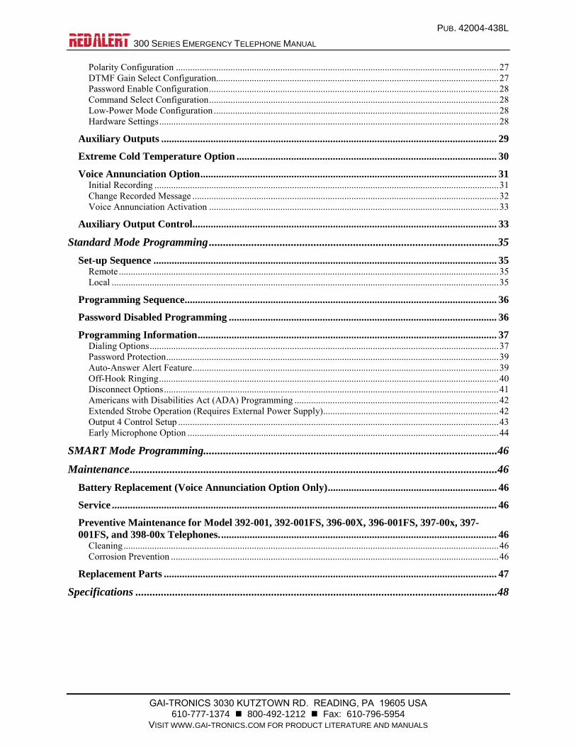
T A B L E O F C O N T E N T S
Confidentiality Notice .....................................................................................................................1
Product Overview ............................................................................................................................1
Telephones ............................................................................................................................................... 1
Telephone Options .................................................................................................................................. 4
Telephone Management Application (TMA) ....................................................................................... 4
Standard Operation .........................................................................................................................5
Emergency Call Operation ..................................................................................................................... 5
Non-Emergency Call Operation ............................................................................................................ 6
Non-Emergency Assistance Operation (Models 396-00x and 396-001FS) ......................................... 6
Receiving a Call ....................................................................................................................................... 6
Disconnecting a Call ............................................................................................................................... 7
Location Identification Code Dialing .................................................................................................... 7
Installation ......................................................................................................................................7
Safety Guidelines ..................................................................................................................................... 7
General Installation Guidelines ............................................................................................................. 8
Security Hardware .................................................................................................................................. 8
Conduit Installation Details ................................................................................................................... 8
Models 393-00x, 393AL-00x, and 394AL-00x ..................................................................................... 10
Models 392-001, 396-00x, 397-00x, and 398-00x – Stanchion or Flush-Mount Applications ......... 12
Models 392-001FS, 396-001FS, and 397-001FS – Flush-Mount Applications ................................. 16
Retro-fit Models .................................................................................................................................... 19
External Power for -003 and -004 Models .......................................................................................... 26
Connecting a GAI-Tronics Strobe ....................................................................................................... 26
Setup ..............................................................................................................................................27
Hardware Configuration ...................................................................................................................... 27 Auto-answer Configuration ................................................................................................................................ 27
PUB. 42004-438L
300 SERIES EMERGENCY TELEPHONE MANUAL
GAI-TRONICS 3030 KUTZTOWN RD. READING, PA 19605 USA 610-777-1374 800-492-1212 Fax: 610-796-5954
VISIT WWW.GAI-TRONICS.COM FOR PRODUCT LITERATURE AND MANUALS
Polarity Configuration ........................................................................................................................................ 27 DTMF Gain Select Configuration ....................................................................................................................... 27 Password Enable Configuration .......................................................................................................................... 28 Command Select Configuration .......................................................................................................................... 28 Low-Power Mode Configuration ........................................................................................................................ 28 Hardware Settings ............................................................................................................................................... 28
Auxiliary Outputs ................................................................................................................................. 29
Extreme Cold Temperature Option .................................................................................................... 30
Voice Annunciation Option .................................................................................................................. 31 Initial Recording ................................................................................................................................................. 31 Change Recorded Message ................................................................................................................................. 32 Voice Annunciation Activation .......................................................................................................................... 33
Auxiliary Output Control ..................................................................................................................... 33
Standard Mode Programming ......................................................................................................35
Set-up Sequence .................................................................................................................................... 35 Remote ................................................................................................................................................................ 35 Local ................................................................................................................................................................... 35
Programming Sequence ........................................................................................................................ 36
Password Disabled Programming ....................................................................................................... 36
Programming Information ................................................................................................................... 37 Dialing Options ................................................................................................................................................... 37 Password Protection ............................................................................................................................................ 39 Auto-Answer Alert Feature ................................................................................................................................. 39 Off-Hook Ringing ............................................................................................................................................... 40 Disconnect Options ............................................................................................................................................. 41 Americans with Disabilities Act (ADA) Programming ...................................................................................... 42 Extended Strobe Operation (Requires External Power Supply).......................................................................... 42 Output 4 Control Setup ....................................................................................................................................... 43 Early Microphone Option ................................................................................................................................... 44
SMART Mode Programming........................................................................................................46
Maintenance ..................................................................................................................................46
Battery Replacement (Voice Annunciation Option Only) ................................................................. 46
Service .................................................................................................................................................... 46
Preventive Maintenance for Model 392-001, 392-001FS, 396-00X, 396-001FS, 397-00x, 397-001FS, and 398-00x Telephones. .......................................................................................................... 46
Cleaning .............................................................................................................................................................. 46 Corrosion Prevention .......................................................................................................................................... 46
Replacement Parts ................................................................................................................................ 47
Specifications ................................................................................................................................48

PUB. 42004-438L
GAI-TRONICS 3030 KUTZTOWN RD. READING, PA 19605 USA 610-777-1374 800-492-1212 Fax: 610-796-5954
VISIT WWW.GAI-TRONICS.COM FOR PRODUCT LITERATURE AND MANUALS
G A I - T R O N I C S ® A H U B B E L L C O M P A N Y
300 Series Emergency
Telephone Manual
Confidentiality Notice
This manual is provided solely as an installation, operation, and maintenance guide, which contains
sensitive business and technical information, that is confidential and proprietary to GAI-Tronics. GAI-
Tronics retains all intellectual property and other rights in or to the information contained herein, and
such information may only be used in connection with the operation of your GAI-Tronics product or
system. This manual may not be disclosed in any form, in whole or in part, directly or indirectly, to any
third party.
Product Overview
Telephones
RED ALERT® 300 Series Emergency Telephones have been designed for maximum environmental
sustainability, high audio quality and unparalleled monitoring capability. In addition to providing hands-
free, two-way communications; a RED ALERT® telephone can tell you its location, report call activity,
activate up to two peripheral devices, and let you know when it is experiencing problems. When used
with our Telephone Management Application (TMA) software, RED ALERT® telephones will reduce
system test and maintenance time while greatly decreasing liability issues associated with undetected,
faulty equipment. All models are weatherproof rated Type 3R.
All RED ALERT® Emergency Telephone models incorporate SMART (Self-Monitoring and Reporting
Telephone) Technology. This leading-edge technology becomes active only when connected to GAI-
Tronics TMA software for system monitoring. The actual operation of the RED ALERT® Emergency
Telephone is the same regardless of whether or not TMA is installed. With TMA installed, the telephones
will be polled and will report their health status. Without TMA installed, no polling (or data collection)
will occur.
RED ALERT® Emergency Telephones also comply with the Americans with Disabilities Act (ADA) in
both physical and operational characteristics. Each Emergency Telephone includes a Braille label for
vision-impaired individuals for identifying the “emergency” functions of the telephone and a visual CALL
RECEIVED WHEN LIT LED for hearing-impaired individuals. The LED will flash when either the
HELP or CALL (if equipped) buttons are depressed. The LED will become steadily illuminated when the
call has been answered. This LED will remain illuminated until the call has been terminated.
PUB. 42004-438L
300 SERIES EMERGENCY TELEPHONE MANUAL PAGE 2 of 50
p:\standard ioms - current release\42004 instr. manuals\42004-438l.docx 07/16
The HELP push button on each emergency telephone can be programmed to dial three different telephone
numbers. These include a primary telephone number and two “rollover” telephone numbers. In the event
an emergency call cannot connect to the primary telephone number (i.e., a busy signal or no answer), the
emergency telephone will automatically dial the first rollover number. If the first rollover number is busy
or is not answered, the telephone will automatically dial the second rollover telephone number.
All RED ALERT® Emergency Telephones are line-powered and can be connected to any of the following
networks:
Central Office (C.O.) line to the Public Switched Telephone Network (PSTN)
24 V dc or 48 V dc analog station port of a Private Branch Exchange (PBX), Private Automatic
Branch Exchange (PABX), or Key Service Unit (KSU).
NOTE: Connection to pay telephone extensions or shared service (party) lines should be avoided.
Each telephone requires a minimum line current of 24 mA for proper operation. For operation below
−4 °F (−20 °C), GAI-Tronics offers an extreme cold weather option that includes a plug-in power supply
(120 V ac required). This option will allow operation to −40 °C.
The RED ALERT® Emergency Telephones provide the flexibility to address a diverse range of
applications. A wide variety of functions can be achieved by altering the configuration data stored in the
telephone’s non-volatile memory. These configuration options include:
Pre-programmed auto-dial telephone numbers
Call termination method (automatic or manual)
Maximum call duration
Answering options
Values for these functions are initially programmed during factory testing. These settings can be changed
remotely from a touch-tone telephone, locally (with an integral or portable keypad), or via TMA.
Emergency auto-dial telephone numbers are typically programmed in accordance with existing security
plans. Most applications will require very little additional programming, as factory defaults are typically
sufficient.
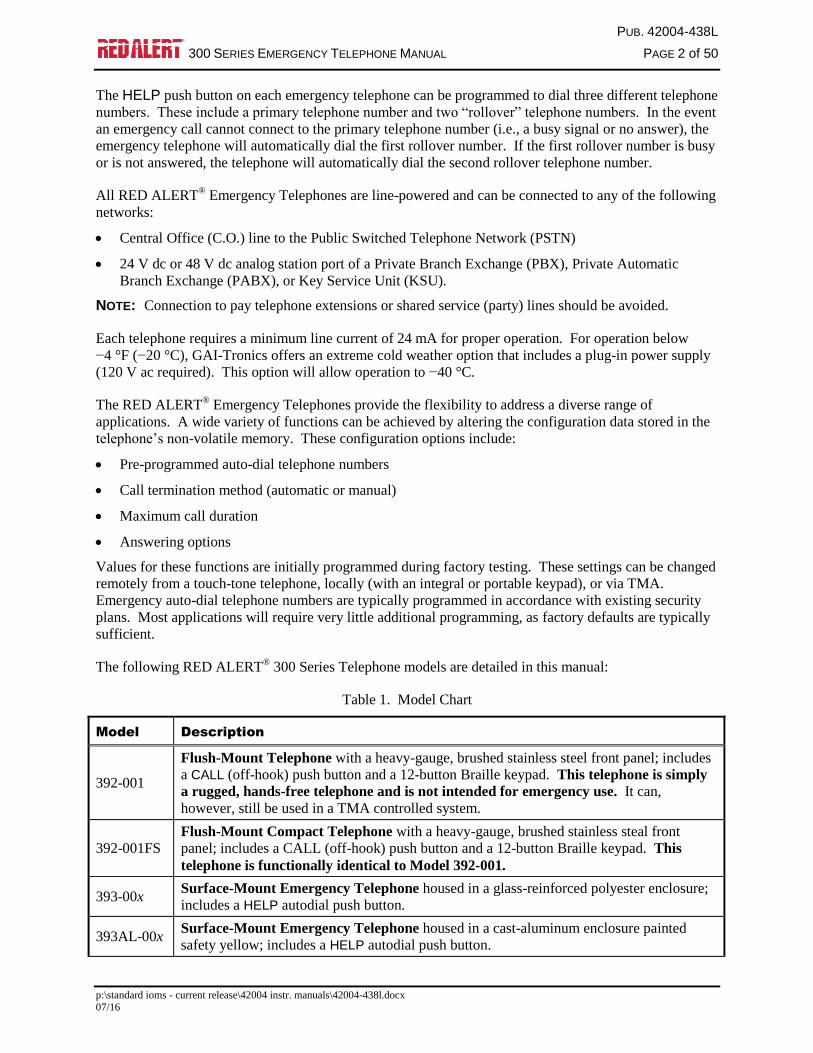
The following RED ALERT® 300 Series Telephone models are detailed in this manual:
Table 1. Model Chart
Model Description
392-001
Flush-Mount Telephone with a heavy-gauge, brushed stainless steel front panel; includes
a CALL (off-hook) push button and a 12-button Braille keypad. This telephone is simply
a rugged, hands-free telephone and is not intended for emergency use. It can,
however, still be used in a TMA controlled system.
392-001FS
Flush-Mount Compact Telephone with a heavy-gauge, brushed stainless steal front
panel; includes a CALL (off-hook) push button and a 12-button Braille keypad. This
telephone is functionally identical to Model 392-001.
393-00x Surface-Mount Emergency Telephone housed in a glass-reinforced polyester enclosure;
includes a HELP autodial push button.
393AL-00x Surface-Mount Emergency Telephone housed in a cast-aluminum enclosure painted
safety yellow; includes a HELP autodial push button.
PUB. 42004-438L
300 SERIES EMERGENCY TELEPHONE MANUAL PAGE 3 of 50
p:\standard ioms - current release\42004 instr. manuals\42004-438l.docx 07/16
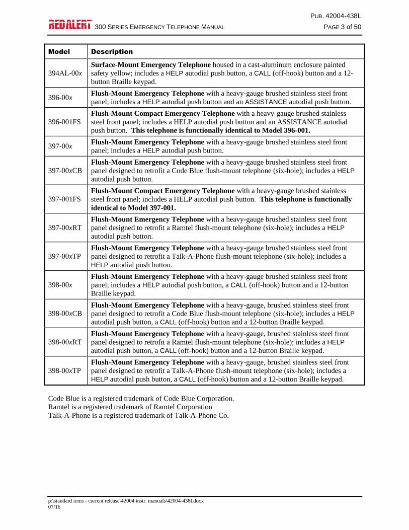
Model Description
394AL-00x
Surface-Mount Emergency Telephone housed in a cast-aluminum enclosure painted
safety yellow; includes a HELP autodial push button, a CALL (off-hook) button and a 12-
button Braille keypad.
396-00x Flush-Mount Emergency Telephone with a heavy-gauge brushed stainless steel front
panel; includes a HELP autodial push button and an ASSISTANCE autodial push button.
396-001FS
Flush-Mount Compact Emergency Telephone with a heavy-gauge brushed stainless
steel front panel; includes a HELP autodial push button and an ASSISTANCE autodial
push button. This telephone is functionally identical to Model 396-001.
397-00x Flush-Mount Emergency Telephone with a heavy-gauge brushed stainless steel front
panel; includes a HELP autodial push button.
397-00xCB Flush-Mount Emergency Telephone with a heavy-gauge brushed stainless steel front
panel designed to retrofit a Code Blue flush-mount telephone (six-hole); includes a HELP
autodial push button.
397-001FS
Flush-Mount Compact Emergency Telephone with a heavy-gauge brushed stainless
steel front panel; includes a HELP autodial push button. This telephone is functionally
identical to Model 397-001.
397-00xRT
Flush-Mount Emergency Telephone with a heavy-gauge brushed stainless steel front
panel designed to retrofit a Ramtel flush-mount telephone (six-hole); includes a HELP
autodial push button.
397-00xTP Flush-Mount Emergency Telephone with a heavy-gauge brushed stainless steel front
panel designed to retrofit a Talk-A-Phone flush-mount telephone (six-hole); includes a
HELP autodial push button.
398-00x Flush-Mount Emergency Telephone with a heavy-gauge brushed stainless steel front
panel; includes a HELP autodial push button, a CALL (off-hook) button and a 12-button
Braille keypad.
398-00xCB Flush-Mount Emergency Telephone with a heavy-gauge, brushed stainless steel front
panel designed to retrofit a Code Blue flush-mount telephone (six-hole); includes a HELP
autodial push button, a CALL (off-hook) button and a 12-button Braille keypad.
398-00xRT
Flush-Mount Emergency Telephone with a heavy-gauge, brushed stainless steel front
panel designed to retrofit a Ramtel flush-mount telephone (six-hole); includes a HELP
autodial push button, a CALL (off-hook) button and a 12-button Braille keypad.
398-00xTP
Flush-Mount Emergency Telephone with a heavy-gauge, brushed stainless steel front
panel designed to retrofit a Talk-A-Phone flush-mount telephone (six-hole); includes a
HELP autodial push button, a CALL (off-hook) button and a 12-button Braille keypad.
Code Blue is a registered trademark of Code Blue Corporation.
Ramtel is a registered trademark of Ramtel Corporation
Talk-A-Phone is a registered trademark of Talk-A-Phone Co.
PUB. 42004-438L
300 SERIES EMERGENCY TELEPHONE MANUAL PAGE 4 of 50
p:\standard ioms - current release\42004 instr. manuals\42004-438l.docx 07/16
Telephone Options
RED ALERT® Telephones are available with two different factory-installed options (or both options
installed). These options are:
Voice Annunciation Option allows local or remote speech programming for location identification
purposes, instructions, or any other desired messaging requirement. The message can be programmed
locally at the telephone or remotely via dial-up. The recorded message will be activated when the called
party transmits a DTMF command.
Extreme Cold Weather Option allows the telephone to operate in temperatures as low as −40 °C
(standard operating temperature is −20 °C). This option includes a plug-in power supply and non-tactile
(non-moveable) HELP and/or CALL (if equipped) push buttons.
All RED ALERT® Telephones are ordered for standard operation (no options) by using a “-001” suffix
(example: 393-001 or 397-001CB). Telephones with factory-installed options are ordered based on the
following chart.
Table 2. Option Model Chart (Not applicable to “FS” series models)
Option Suffix Description
-002 or -002xx Voice Annunciation Option, factory-installed (examples: 393-002 or 397-002CB)
-003 or -003xx Extreme Cold Temperature Option, factory-installed (examples: 393-003 or
397-003CB
-004 or -004xx Voice Annunciation and Extreme Cold Temperature Options, factory-installed
(examples: 393-004 or 397-004CB)
Each RED ALERT® Telephone is capable of providing two isolated control outputs in the form of a dry
(volt-free) contact closure rated at 125 mA. One output is controlled by the telephone’s emergency call
activation and the other is remotely controlled by a called party DTMF code activation.
Telephone Management Application (TMA)
GAI-Tronics’ TMA software is a maintenance data collection and reporting tool that allows users to view
and report the health of the RED ALERT® Emergency Telephones. RED ALERT
® Telephones can
function with or without the TMA software application installed. The decision to use TMA can be made
at any time and is not needed for telephone operation. Installation of TMA is not required until system
monitoring is desired.
When used with TMA, each telephone will typically be polled to determine the health of the unit and
report the following:
Stuck push buttons
Microphone failure
Speaker failure
Microprocessor health
Line interrupt (power)
Low battery life (Voice Annunciation option only)
PUB. 42004-438L
300 SERIES EMERGENCY TELEPHONE MANUAL PAGE 5 of 50
p:\standard ioms - current release\42004 instr. manuals\42004-438l.docx 07/16
The basic TMA package (Model 12509-042) includes a single line transceiver for polling a single
telephone at a time. With each telephone requiring approximately 90 seconds to relay its health status to
TMA, the ability to poll multiple telephones simultaneously may become very important in larger
systems. A TMA expansion kit (Model 12509-043) is available and is required for each additional
connected telephone line, with a maximum of eight lines allowed. This allows a maximum of eight
telephones to be polled simultaneously. A dedicated PC is strongly recommended for TMA operation.
A dedicated telephone line per RED ALERT® Telephone is required when using TMA in its typical
“polling” operation. Although it is not recommended, RED ALERT® Telephones can share a telephone
line with the understanding that if two or more telephones are put into use simultaneously, the line current
could drop sufficiently to disconnect the telephone call completely. This will depend on the line current,
the length of the cable run, and the condition of the telephone cable. When sharing a telephone line using
TMA, the telephone must be scheduled to “call-in” instead of being polled by TMA.
TMA users can schedule auto-dial maintenance calls to alert maintenance personnel of any unusual sensor
or fault conditions that exist. RED ALERT® Telephones can also be programmed to generate an auto-dial
maintenance call when certain sensor events are discovered. Access to the RED ALERT® Telephone
settings is restricted through the use of the maintenance access PIN, which should be disclosed only to
trained maintenance personnel.
Standard Operation
Four types of telephones are described in this manual:
Single emergency push-button operation (autodial)
Emergency push button and call push button with keypad
Emergency push button and assistance push button (both autodial)
Call push button with keypad (hands-free standard telephone operation)
This section describes the general operation of each telephone type.
Emergency Call Operation
NOTE: Applicable to telephones equipped with a HELP push button.
1. Press the HELP push button to place an immediate call to a pre-programmed emergency telephone
number; typically a security office, campus police, or 911.
2. The CALL RECEIVED WHEN LIT indicator (LED) operates as follows:
The indicator will begin to flash when the HELP push button is pressed and will light (steadily)
when the telephone detects audio after the call is answered.
- or -
The indicator will begin to flash when the HELP push button is pressed and will light (steadily)
when the called party acknowledges receiving the call by transmitting a DTMF “#” or “*” after
answering the call.
3. Two-way, hands-free conversation can now occur.
PUB. 42004-438L
300 SERIES EMERGENCY TELEPHONE MANUAL PAGE 6 of 50
p:\standard ioms - current release\42004 instr. manuals\42004-438l.docx 07/16
Non-Emergency Call Operation
NOTE: Applicable to telephones equipped with a CALL push button and keypad, with or without a HELP
push button.
The telephone models with keypads can also be used to make non-emergency type calls as follows:
1. Press the CALL push button (dial tone can be heard over the speaker).
2. Use the keypad to dial the desired number.
3. The CALL RECEIVED WHEN LIT indicator (LED) operates as follows:
The indicator will begin to flash when the CALL push button is pressed and will light (steadily)
when the telephone detects audio after the call is answered.
- or -
The indicator will begin to flash when the CALL push button is pressed and will light (steadily)
when the called party acknowledges receiving the call by transmitting a DTMF “#” or “*” after
answering the call.
4. Press the CALL push button upon completion of the call (hang up).
NOTE: The CALL push button can be configured to auto-dial, thereby overriding the keypad dialing
feature. This operation can be used to call a central telephone number and use the keypad to make feature
selections.
Non-Emergency Assistance Operation (Models 396-00x and 396-001FS)
1. Press the ASSISTANCE push button to place an immediate call to a pre-programmed assistance
telephone number; typically a dormitory, garage, or general assistance/information office).
2. The CALL RECEIVED WHEN LIT indicator (LED) operates as follows:
The indicator will begin to flash when the ASSISTANCE push button is pressed and will light
(steadily) when the telephone detects audio after the call is answered.
- or -
The indicator will begin to flash when the ASSISTANCE push button is pressed and will light
(steadily) when the called party acknowledges receiving the call by transmitting a DTMF “#”
or “*” after answering the call.
3. Two-way hands-free conversation can now occur.
Receiving a Call
Each RED ALERT® Telephone can be programmed to auto-answer an incoming call. When the
emergency telephone extension is dialed, the unit will automatically answer, generate a pair of triple
“beep” tones, and two-way, hands-free conversation can occur.

PUB. 42004-438L
300 SERIES EMERGENCY TELEPHONE MANUAL PAGE 7 of 50
p:\standard ioms - current release\42004 instr. manuals\42004-438l.docx 07/16
Disconnecting a Call
There are several methods by which a RED ALERT® Emergency Telephone can both manually and
automatically disconnect calls. The disconnect methods include the following:
Remote disconnect of an emergency call – Called party transmits either a “ ## ” or “ *99 ” DTMF
control command.
Manual disconnect of an emergency call – Press the HELP push button approximately 15 seconds
after the initial activation.
NOTE: Pressing the HELP push button a second time within 10 seconds of initially activating the
call will have no effect on the telephone’s operation. This prevents an anxious or hurried user from
disconnecting the call prematurely (this feature can be disabled).
Manual disconnect of a non-emergency call – Press the CALL or ASSISTANCE button a second
time.
Automatic disconnect:
- All calls; loop current-drop disconnect
- All calls; maximum call duration timeout (configurable from 1 minute to 4.5 hours)
- All voice calls; call progress tones (i.e., busy signal/fast busy, or reorder, tone) and, when enabled,
dial tone.
Refer to the “Programming” section of this manual for factory defaults and available options.
Location Identification Code Dialing
The Location Identification Code feature enables the called party to quickly and easily locate the source
of the emergency call. When the calling individual presses the HELP push button, the called party
(typically the security operator) presses the “*” button on their phone. The RED ALERT® Telephone
detects the “*” signal and transmits a three-digit, DTMF, location identification code. This location code
can be displayed on a customer-provided DTMF decoder/display.
Please refer to the “Americans with Disabilities Act (ADA) Programming” section on Page 42.
Installation
ATTENTION Installation should be performed by qualified personnel and only in
accordance with the National Electrical Code or applicable local codes.
Safety Guidelines
When installing any GAI-Tronics telephone equipment, please adhere to the following guidelines to
ensure the safety of all personnel:
Do not install telephone wiring during a lightning storm.
Electrostatic Discharge (ESD) Protection: Your telephone may have an earth ground terminal
provision. If so, ensure that it is connected to ground in accordance with all local safety regulations
and the National Electrical Code (NEC). Grounding has to be ensured for safe and stable
communications. Do not use long and coiled ground wires. Trim ground wires to the required
length. Use a star configuration whenever possible. Please note proper grounding does not eliminate
the need for lightning protection for the telephone or the telephone system.

PUB. 42004-438L
300 SERIES EMERGENCY TELEPHONE MANUAL PAGE 8 of 50
p:\standard ioms - current release\42004 instr. manuals\42004-438l.docx 07/16
Install a UL Listed lightning arrestor on any telephone installed where the telephone or telephone
cable is at risk of being exposed to lightning strikes. The lightning arrestor must be installed as close
to the telephone as possible to maximize the protection. It must not be installed within the enclosure
supplied with the phone.
Do not install telephone jacks in wet locations unless the jack is specifically designed for wet
locations.
Do not touch uninsulated telephone wires or terminals unless the telephone line has been
disconnected at the network interface.
General Installation Guidelines
As previously noted, the preferred system configuration is a dedicated telephone line per RED ALERT®
Telephone. This is an actual requirement when using TMA in its typical “polling” operation.
Although it is not recommended, a RED ALERT® Telephone can share a telephone line with another
RED ALERT® Telephone with the understanding that if two or more telephones are put into use
simultaneously the line current could drop sufficiently to disconnect the telephone call completely.
Additional “line sharing” or “party line” configuration issues could include sporadic telephone operation,
difficulties with programming, or premature disconnection of calls. Special system features (voice mail,
call waiting, etc.) could also create problems if not disabled. Successful shared line operation will depend
on the line current, the length of the cable run, and the condition of the telephone cable.
NOTE: A RED ALERT® telephone should never be installed on the same telephone line as any
other (non-RED ALERT®) telephone type.
When sharing a telephone line using TMA, the telephone must be scheduled to “call-in” instead of being
polled by TMA.
Security Hardware
All of the telephones described in this manual are vandal resistant. The front panel for each telephone
covered in this manual is attached to its enclosure with security screws. A GAI-Tronics Model 233-001
Security Screwdriver or Torx T-25 security head tip (sold separately) is required for installing the
telephone.
Conduit Installation Details
GAI-Tronics recommends installing telephone lines in conduit to protect against accidental damage and
vandalism. To prevent moisture from entering the enclosure, we strongly recommend the following:
Conduit should enter the enclosure from the bottom whenever possible.
Sealed fittings should be installed at all cable entry points.
Silicone sealant or equivalent should be applied around and inside all conduit entries to prevent
moisture ingress.

PUB. 42004-438L
300 SERIES EMERGENCY TELEPHONE MANUAL PAGE 9 of 50
p:\standard ioms - current release\42004 instr. manuals\42004-438l.docx 07/16
Please refer to the examples below for the recommended conduit installation details.
Figure 1. Bottom entry conduit recommended for
non-metallic enclosures
Figure 2. Top entry conduit installation for non-
metallic enclosures (NOT recommended)
Figure 3. Bottom entry conduit installation details
for metallic enclosures
Figure 4. Top entry conduit installation details for
metallic enclosures (NOT recommended)
PUB. 42004-438L
300 SERIES EMERGENCY TELEPHONE MANUAL PAGE 10 of 50
p:\standard ioms - current release\42004 instr. manuals\42004-438l.docx 07/16
Models 393-00x, 393AL-00x, and 394AL-00x
The mounting and wiring instructions are as follows:
1. Remove the four security screws from the front
panel and set the panel assembly aside, protecting it
from possible damage.
2. Position the enclosure on the mounting surface.
The enclosure provides four 0.28-inch mounting
holes in a 7.0 8.5-inch hole pattern. Secure the
enclosure to its mounting surface with four ¼-inch
diameter bolts of the appropriate length for the
surface.
NOTE: When using the GAI-Tronics Model
231-001 Pole Mounting Kit, follow the mounting
instructions provided in the kit.
3. For Model 393-00x only: Create a conduit access
hole using a Greenlee-type punch that is equivalent in
size to the conduit diameter. Bottom entry is strongly
recommended. Insert a conduit fitting in the access
hole.
4. Install conduit as required. Refer to conduit installation details on Page 9.
Note: Use silicone sealant or equivalent around and inside all conduit entries.
5. Pull the telephone line through the conduit and into the enclosure. Connect the telephone line to the
customer-supplied telephone line surge suppressor (if applicable) and modular jack (USOC RJ11 or
CA11A) provided with the unit.
NOTE: The modular jack may be mounted inside the telephone. Telephone line connections directly
to TB1 are acceptable.
6. Allow the telephone a minimum of 35 seconds to initialize.
7. Using the “Setup” section of this manual,
Configure the hardware as required. Refer to the “Hardware Configuration” section on Page 27
for details.
Adjust the audio levels, if necessary. Refer to Figure 32 for “Speaker Volume” and “Microphone
Sensitivity” potentiometer locations.
Perform the initial programming. Refer to the “Programming” section on Page 35.
8. Verify operation by calling to and from another telephone.
9. Complete the installation by attaching the front panel assembly to the rear enclosure using the four
security screws, 10–12 in-lbs. of torque recommended.
Figure 5. Model 393-00x Emergency Telephone
in a Non-Metallic Enclosure
PUB. 42004-438L
300 SERIES EMERGENCY TELEPHONE MANUAL PAGE 11 of 50
p:\standard ioms - current release\42004 instr. manuals\42004-438l.docx 07/16
Figure 6. Model 393AL-00x
Figure 7. Model 394AL-00x
Figure 8. Model 393-00x, 393AL-00x, and 394AL-00x Component Locations

PUB. 42004-438L
300 SERIES EMERGENCY TELEPHONE MANUAL PAGE 12 of 50
p:\standard ioms - current release\42004 instr. manuals\42004-438l.docx 07/16
Models 392-001, 396-00x, 397-00x, and 398-00x – Stanchion or Flush-Mount
Applications
1. When mounting in a GAI-Tronics Model 234 Series Stanchion, or for flush-mount installations, the
supplied back box must be used to mount the Model 397-00x, 396-00x, 398-00x, or 392-001
Telephone. Mount the back box to the structure using appropriate hardware. Refer to Figure 13
cutout dimensions.
NOTE: If mounted outdoors, the installation of a telephone line suppressor (customer-supplied) on the
telephone line is recommended.
Figure 9. Model 392-001
Figure 10. Model 396-00x
Figure 11. Model 397-00x
Figure 12. Model 398-00x

PUB. 42004-438L
300 SERIES EMERGENCY TELEPHONE MANUAL PAGE 13 of 50
p:\standard ioms - current release\42004 instr. manuals\42004-438l.docx 07/16
2. Remove the tapered plug from either of the cable entry holes in the back box, and install the telephone line and cable fitting.
NOTE: Telephone line connections directly to TB1 are acceptable.
3. If using the modular jack, remove the cover, and connect the telephone line’s tip (+) wire to the green wire on the modular jack, and the ring (-) wire to the red wire on the modular jack. Replace the modular jack cover.
4. Connect the telephone’s modular plug to a USOC RJ11 or CA11A (Canada) modular connector or (if applicable) the telephone line suppressor. (An inline coupler is provided for use, if necessary.) Refer to Figure 13. Model 392-001 396-00x, 397-00x, and 398-00x Mounting Details for the Model 397-00x, 396-00x, 398-00x and 392-001 component locations.
5. Allow the telephone a minimum of 35 seconds to initialize.
6. Using the “Setup” section of this manual,
Configure the hardware as required. Refer to the “Hardware Configuration” section on Page 27 for details.
Adjust the audio levels, if necessary. Refer to Figure 32 for “Speaker Volume” and “Microphone Sensitivity” potentiometer locations.
Perform the initial programming. Refer to the “Standard Mode Programming” section on Page 35.
7. Verify operation by calling to and from another phone.
8. Complete the installation by attaching the front panel assembly to the rear enclosure mounting flanges using the six supplied #10-32 security screws and washers, 10–12 in-lbs. of torque recommended.

PUB. 42004-438L
300 SERIES EMERGENCY TELEPHONE MANUAL PAGE 14 of 50
p:\standard ioms - current release\42004 instr. manuals\42004-438l.docx 07/16
Figure 13. Model 392-001 396-00x, 397-00x, and 398-00x Mounting Details

PUB. 42004-438L
300 SERIES EMERGENCY TELEPHONE MANUAL PAGE 15 of 50
p:\standard ioms - current release\42004 instr. manuals\42004-438l.docx 07/16
Figure 14. Cutout for Model 392-001, 396-00x, 397-00x, and 398-00x

PUB. 42004-438L
300 SERIES EMERGENCY TELEPHONE MANUAL PAGE 16 of 50
p:\standard ioms - current release\42004 instr. manuals\42004-438l.docx 07/16
Models 392-001FS, 396-001FS, and 397-001FS – Flush-Mount Applications These compact models are designed to be installed in flush mount openings measuring 7.75 H ×5.75 W inches.
R
Figure 15. Model 392-001FS
396-001FS
R
Figure 16. Model 396-001FS
R
Figure 17. Model 397-001FS
1. Remove the back box from the front cover.
NOTE: If mounted outdoors, the installation of a telephone line suppressor (customer-supplied) on the telephone line is recommended.
2. Feed the telephone line through either of the cable entry holes in the back box.
NOTE: Telephone line connections directly to TB1 are acceptable.

PUB. 42004-438L
300 SERIES EMERGENCY TELEPHONE MANUAL PAGE 17 of 50
p:\standard ioms - current release\42004 instr. manuals\42004-438l.docx 07/16
3. The telephone line is equipped with a USOC RJ11C-type modular connector. (An inline coupler is provided for use, if necessary.) Plug the connector into the mating connector inside the enclosure.
4. Re-install the back box.
5. Allow the telephone a minimum of 35 seconds to initialize.
6. Using the “Setup” section of this manual,
Configure the hardware as required. Refer to the “Hardware Configuration” section on Page 27 for details.
Adjust the audio levels if necessary. Refer to Figure 32 for “Speaker Volume” and “Microphone Sensitivity” potentiometer locations.
Perform the initial programming. Refer to the “Standard Mode Programming” section on Page 35.
7. Verify operation by calling to and from another phone.
8. Complete the installation by attaching the front panel assembly to the mounting surface using the six supplied #10-32 security screws, 10–12 in-lbs. of torque recommended.
Figure 18. Model 392-001FS, 396-001FS, and 397-001FS Back Box
PUB. 42004-438L
300 SERIES EMERGENCY TELEPHONE MANUAL PAGE 18 of 50
p:\standard ioms - current release\42004 instr. manuals\42004-438l.docx 07/16
Figure 19. Cutout for Model 392-001FS, 396-001FS, and 397-001FS

PUB. 42004-438L
300 SERIES EMERGENCY TELEPHONE MANUAL PAGE 19 of 50
p:\standard ioms - current release\42004 instr. manuals\42004-438l.docx 07/16
Retro-fit Models The appropriate RED ALERT® retrofit models can be installed in Code Blue, Ramtel, or Talk-A-Phone enclosures utilizing a six-hole mounting pattern.
1. Remove the back box from the front cover.
2. Feed the telephone line through either of the cable entry holes on the back box.
3. Re-install the back box.
4. The telephone line is equipped with a USOC RJ11C-type modular connector. (An inline coupler is provided for use, if necessary.) Plug the connector into the mating connector inside the enclosure.
5. Allow the telephone a minimum of 35 seconds to initialize.
6. Using the “Setup” section of this manual,
Configure the hardware as required. Refer to the “Hardware Configuration” section on Page 27 for details.
Adjust the audio levels if necessary. Refer to Figure 32 for “Speaker Volume” and “Microphone Sensitivity” potentiometer locations.
Perform the initial programming. Refer to the “Standard Mode Programming” section on Page 35.
7. Verify operation by calling to and from another phone.
8. Complete the installation by attaching the front panel assembly to the rear enclosure using the security screws, 10–12 in-lbs. of torque recommended.
Figure 20. Model 397-00xCB
Figure 21. Model 398-00xCB
PUB. 42004-438L
300 SERIES EMERGENCY TELEPHONE MANUAL PAGE 20 of 50
p:\standard ioms - current release\42004 instr. manuals\42004-438l.docx 07/16
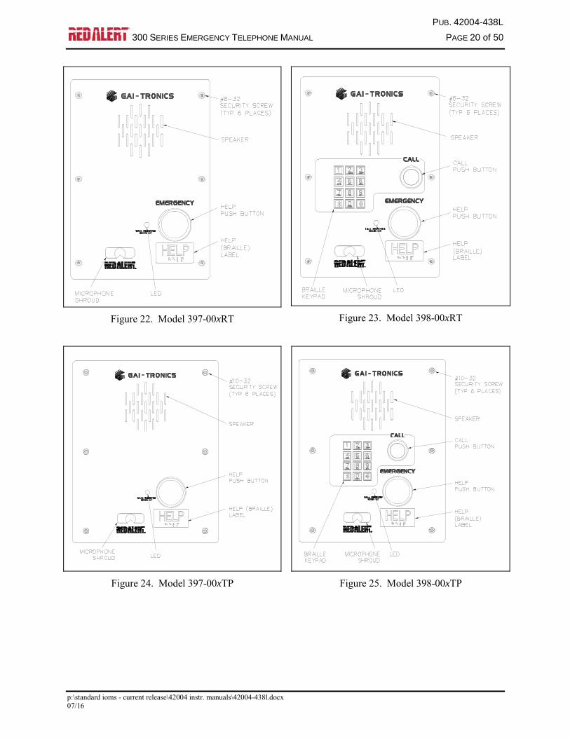
Figure 22. Model 397-00xRT
Figure 23. Model 398-00xRT
Figure 24. Model 397-00xTP
Figure 25. Model 398-00xTP

PUB. 42004-438L
300 SERIES EMERGENCY TELEPHONE MANUAL PAGE 21 of 50
p:\standard ioms - current release\42004 instr. manuals\42004-438l.docx 07/16
Figure 26. Back Box for Ramtel (RT) and Code Blue (CB)

PUB. 42004-438L
300 SERIES EMERGENCY TELEPHONE MANUAL PAGE 22 of 50
p:\standard ioms - current release\42004 instr. manuals\42004-438l.docx 07/16
Figure 27. Cutout for Ramtel (RT) Telephones

PUB. 42004-438L
300 SERIES EMERGENCY TELEPHONE MANUAL PAGE 23 of 50
p:\standard ioms - current release\42004 instr. manuals\42004-438l.docx 07/16
Figure 28. Cutout for Code Blue (CB) Telephones

PUB. 42004-438L
300 SERIES EMERGENCY TELEPHONE MANUAL PAGE 24 of 50
p:\standard ioms - current release\42004 instr. manuals\42004-438l.docx 07/16
Figure 29. Back Box for Talk-A-Phone (TP)

PUB. 42004-438L
300 SERIES EMERGENCY TELEPHONE MANUAL PAGE 25 of 50
p:\standard ioms - current release\42004 instr. manuals\42004-438l.docx 07/16
Figure 30. Cutout for Talk-A-Phone (TP) Telephones

PUB. 42004-438L
300 SERIES EMERGENCY TELEPHONE MANUAL PAGE 26 of 50
p:\standard ioms - current release\42004 instr. manuals\42004-438l.docx 07/16
External Power for -003 and -004 Models The Plug-in Power Supply is used for operations below −4 ºF (−20 ºC) and requires 120 V ac input to provide a 5 V dc output to the unit. The Plug-in Power Supply is provided with a 4-foot power cable with integral connector that plugs into P17 on the telephone PCBA. Remove the existing jumper from P17 pins 3 and 4 and install it onto the adjacent header J18 when using the plug-in power supply. See Figure 32 on Page 29 for jumper locations.
NOTE: The external power supply provided with these models does not provide telephone line power for communications. It simply activates a heater circuit to allow operation to −40 ºC.
Connecting a GAI-Tronics Strobe Figure 31 below shows a typical connection detail of a GAI-Tronics 540-001/530-001/531A Strobe (sold separately).
Figure 31. (Model 398-00x is shown as an example) Connection to Optional GAI-Tronics 540-001/530-001/531A Strobe

PUB. 42004-438L
300 SERIES EMERGENCY TELEPHONE MANUAL PAGE 27 of 50
p:\standard ioms - current release\42004 instr. manuals\42004-438l.docx 07/16
Setup
Hardware Configuration
The hardware configuration options are explained in detail in the following sections and the necessary
jumper settings are identified to enable or disable each option. Reading each section and recording the
selected options prior to making the necessary changes is recommended. Create a record of your settings
using Table 3 on Page 28. See Figure 32 on Page 29 for the jumper locations.
Auto-answer Configuration
Factory Setting: Auto-answer feature enabled
The auto-answer feature enables or disables the automatic answering of an incoming call, which allows
TMA to monitor the health of this telephone via polling with SMART operation enabled. When the auto-
answer feature is enabled, the telephone automatically answers the call and attempts to communicate with
TMA. If the caller is not TMA, the telephone automatically transitions to a standard two-way
communication.
Enable: J14 jumper in position EN.
Disable: J14 jumper in position DIS (Do not use this setting except under the direction of GAI-Tronics
personnel.)
NOTE: The auto-answer feature must be enabled to allow the GAI-Tronics Telephone Management
Application PC to contact the telephone or to allow remote touch tone programming.
Polarity Configuration
Factory Setting: Non-polarity sensitive
This telephone can be configured to be polarity or non-polarity sensitive. With the non-polarized setting,
the telephone operates regardless of tip and ring polarity. With the polarized setting, the telephone will
only operate when the telephone line’s positive terminal is connected to the tip terminal. Use the polarity
sensitive setting to allow a line voltage reversal disconnect signal to disconnect the call.
Non-polarity Sensitive: J6 jumper in position NON.
Polarity Sensitive: J6 jumper on in position POL.
DTMF Gain Select Configuration
Factory Setting: Low Gain selected.
Two gain selections are available in the DTMF detection circuit. In most installations, the low gain
setting is recommended. The high gain setting may be necessary if the telephone is not responding to
manual or TMA-generated DTMF commands.
Low Gain Selected: J17 jumper in position LO.
High Gain Selected: J17 jumper in position HI.

PUB. 42004-438L
300 SERIES EMERGENCY TELEPHONE MANUAL PAGE 28 of 50
p:\standard ioms - current release\42004 instr. manuals\42004-438l.docx 07/16
Password Enable Configuration
Factory Setting: Password Enabled
This telephone can be configured to enable or disable the password protection for programming (Standard
Mode only). This can be useful when initially programming the telephones.
Password Enabled: J9 jumper in position EN.
Password Disabled: J9 jumper in position DIS.
Command Select Configuration
Factory Setting: Auto
The purpose of J20 is to enable or disable automatic transition to SMART operation. With this jumper in
the standard position, SMART operation is disabled.
SMART Operation Enabled (Auto): J20 jumper in position AUTO.
SMART Operation Disabled (Standard): J20 jumper in position STD.
Low-Power Mode Configuration
Factory Setting: Low-Power Mode Disabled
For some installations in which only minimal loop current is available, the performance of the telephone
may be improved by enabling this feature. Symptoms of minimal loop current may include low speaker
volume and/or momentary muting of audio. In the majority of applications, however, the low-power
mode should be disabled. The low-power mode is enabled by installing the following three jumpers: J21,
J22, and J23.
Low-Power Mode Enabled: Jumpers installed at J21, J22, and J23.
Low-Power Mode Disabled: Jumpers NOT installed at J21, J22, and J23.
Hardware Settings
Table 3. Hardware Settings Table
Default Settings User Settings
Function Setting Jumper/Position Setting Jumper/Position
Auto-answer Enabled J14/EN
Password Protection Enabled J9/EN
Line Polarity Non-polarized J6/NON
Command Select Auto J20/AUTO
DTMF Gain Select Low Gain J17/LO
Low-Power Mode Disabled J21, J22, J23 not
installed

PUB. 42004-438L
300 SERIES EMERGENCY TELEPHONE MANUAL PAGE 29 of 50
p:\standard ioms - current release\42004 instr. manuals\42004-438l.docx 07/16
Auxiliary Outputs Each telephone includes two isolated solid state switches capable of switching a maximum of 125 mA at 48 V dc or 80 mA at 28 V ac. TB2 (OUT1) and TB5 (OUT4) on the emergency telephone PCBA provide the connections for the auxiliary outputs. Refer to Figure 32 for the location of TB2 and TB5.
Refer to the “Auxiliary Output Control” section on Page 33 for additional information.
Figure 32. No. 69577-101 Emergency Telephone PCBA (Top View)

PUB. 42004-438L
300 SERIES EMERGENCY TELEPHONE MANUAL PAGE 30 of 50
p:\standard ioms - current release\42004 instr. manuals\42004-438l.docx 07/16
Extreme Cold Temperature Option RED ALERT® Emergency Telephones equipped with the extreme cold temperature option (-003 and -004 models) are capable of operating to –40 °C (non-option models are rated to –20 °C). This option includes two identifying features.
Each telephone is shipped with a plug-in power supply that requires a 120 V ac input to provide a 5 V dc output to the unit. The power supply is equipped with a 4-foot power cable with integral connector, which plugs into P17 on the telephone PCBA. P17 must be vacated prior to plugging in the power supply. To do so, remove the jumper from P17 pins 3 and 4 and plug it into the adjacent J18 header. Refer to Figure 32 for the connector locations.
In addition to the plug-in power supply, the -003 and -004 models have had the standard tactile (moveable) push buttons (HELP and/or CALL) replaced with non-tactile (non-moveable) push buttons. Use of non-moveable switches eliminates the possibility of water or melting snow from forming and freezing behind the push button, ultimately preventing the movement necessary for activation.
Figure 33. Extreme Cold Temperature Piezo Button (Typical)
NOTE: RED ALERT telephone models ending with the “FS” suffix are equipped with non-tactile pushbutton(s) making them extreme cold weather capable. Operation to −40 °F (−40 °C) can be accomplished by adding a No. 40404-045 Power Supply (120 V ac required).

PUB. 42004-438L
300 SERIES EMERGENCY TELEPHONE MANUAL PAGE 31 of 50
p:\standard ioms - current release\42004 instr. manuals\42004-438l.docx 07/16
Voice Annunciation Option
The voice annunciation option is primarily intended for use during emergency calls placed from a RED
ALERT® Telephone. The voice annunciation option allows local or remote speech programming for
location identification purposes, instructions, or any other desired messaging requirement. The message
can be programmed locally at the telephone or remotely via dial-up.
Initial Recording
NOTE: The easiest method to initially program the voice annunciation recording is to perform the task at
a test bench. This allows control of the audio environment (background noise) and immediate adjustment
of the voice annunciation volume. The set up requires a test telephone line connection for the RED
ALERT® Telephone during programming.
Message Recording
Refer to Figure 32.
1. Remove the front cover to expose the Main PCBA and the “piggy back” voice annunciation PCBA.
Insert two AA lithium batteries (provided with the telephone) into the battery holder of the voice
annunciation PCBA, observing proper polarity.
2. Connect the RED ALERT® telephone to the telephone line and wait 35 seconds for the telephone to
initialize.
3. Locate the “record” push button on the voice annunciation PCBA. Position yourself approximately
12 inches from the microphone (in front of cover). To begin recording, momentarily press the record
push button. After hearing a short beep, begin speaking. The recording should be made in a
conversation-level voice. Maximum message duration is two minutes.
4. Upon completion of the recording, momentarily press the record push button again. A short beep will
again be heard, indicating recording has ended.
5. The recording will automatically play back when the record push button is pressed the second time,
allowing verification of the message. If the message is unsatisfactory, repeat steps three and four.
Volume Adjustment
The voice annunciation volume control is located on the voice annunciation PCBA and is completely
separate from the telephone audio volume control.
1. To adjust the voice annunciation message output volume, the voice annunciation PCBA must first be
placed in “playback” mode. This is accomplished by pressing and holding the record push button
until the playback message is heard over the unit’s integral speaker (typically one to two seconds).
2. Release the record push button. The recorded message will continue to play back (repeating the
message) for a maximum period of one minute.
3. Using the volume control potentiometer located on the voice annunciation PCBA, adjust the volume
as necessary.
4. Momentarily press the record push button to remove the unit from playback mode.
5. These steps can be performed any time volume control adjustment is required.
PUB. 42004-438L
300 SERIES EMERGENCY TELEPHONE MANUAL PAGE 32 of 50
p:\standard ioms - current release\42004 instr. manuals\42004-438l.docx 07/16
Change Recorded Message
It may become necessary to change the voice annunciation recorded message. This can be accomplished
by following the initial message recording steps previously described in the “Initial Recording” section.
The following two methods can be used as alternative methods to programming the message.
Local Record (Integral Keypad Only)
1. Press the CALL push button. When the dial tone is heard from the speaker, simultaneously press the
“1” and “#” keypad buttons. The RED ALERT® Telephone will generate a splash tone (low to high
sequence), followed by a success tone (short beep).
2. Dial the factory-default password 2468 (or appropriate customer-selected password). A success tone
(short beep) is generated to indicate that “standard” programming mode has been accessed.
3. After hearing the password success tone, enter “#75” on the keypad. After hearing a short beep,
begin speaking. The recording should be made in a conversation-level voice.
NOTE: An error tone (two low tones) is generated to indicate an error. If an error tone is generated,
verify the key sequence and enter the “#75” sequence again.
4. Position yourself approximately 12 inches from the microphone (in front of the cover) and begin
speaking in a conversation-level voice. Maximum message duration is two minutes.
5. Press “*” when the recording has been completed.
6. The recording will automatically play back when the “*” DTMF code is pressed.
Remote Record
Remote programming of the voice annunciation option can be accomplished in Standard or SMART
operation mode and is typically used for changing the voice annunciation recording of a RED ALERT®
Telephone that is already installed and operational. This is the recommended method to use for changing
the recording as it does not require access to the telephone’s internal electronics.
Standard Mode
1. Using a touch-tone telephone, call the emergency telephone. The emergency telephone will
automatically answer the call and generate a splash tone (low to high sequence), followed by a
success tone (short beep).
2. Dial the factory-default password 2468 (or appropriate customer-selected password). A success tone
(short beep) is generated to indicate that “standard” programming mode has been accessed.
3. After hearing the password success tone, enter “#75” on the keypad. After hearing a short beep,
begin speaking. The recording should be made in a conversation-level voice.
4. Press “*” when the recording has been completed.
5. The recording will automatically play back when the “*” DTMF code is pressed.
PUB. 42004-438L
300 SERIES EMERGENCY TELEPHONE MANUAL PAGE 33 of 50
p:\standard ioms - current release\42004 instr. manuals\42004-438l.docx 07/16
SMART Mode
Using a touch-tone telephone, call the emergency telephone and listen for a confirmation tone during
ringing, indicating the telephone has answered.
1. Press “***” to enter the programming mode.
2. Wait two seconds.
3. Enter **0000 (0000 is the factory default maintenance PIN number).
4. Enter *20. If the RED ALERT® Telephone has successfully entered into the maintenance mode, it
will respond with six DTMF tones. If access has been denied, it will respond with two DTMF tones.
If this occurs, repeat steps three and four.
5. Press “*8321” and after hearing a short beep, begin speaking.
6. Press “*” when recording has been completed.
7. The recording will automatically play back when the “*” DTMF code is pressed.
Voice Annunciation Activation
Steps for activating the voice annunciation message are:
1. The RED ALERT® Emergency Telephone user presses the HELP push button to autodial a
preprogrammed number.
2. Upon answering or any time during the two-way conversation, the called party can activate the voice
annunciation message by pressing “00” on the telephone keypad.
3. The voice annunciation message is transmitted over the telephone line to be heard by the called party
and is also broadcasted over the RED ALERT® Telephone’s integral speaker.
4. Upon completion of the recorded message, two-way communications may continue.
5. Pressing “00” again will cause the voice annunciation message to replay.
Auxiliary Output Control
As previously noted, each RED ALERT® Telephone is capable of providing two isolated control outputs
in the form of a dry (volt-free) contact closure rated for 125 mA at 48 V dc or 80 mA at 28 V ac.
Output one connects to TB2 on the telephone’s PCBA (refer to Figure 32). This output closes when an
emergency call begins (HELP push button activation only) and remains in that state for the duration of the
telephone call. The typical use of this output is to activate the flashing sequence on a GAI-Tronics
Strobe.
PUB. 42004-438L
300 SERIES EMERGENCY TELEPHONE MANUAL PAGE 34 of 50
p:\standard ioms - current release\42004 instr. manuals\42004-438l.docx 07/16
NOTE: Output one can be programmed to remain closed for up to 255 minutes (in one-minute increments) after the emergency call ends. The strobe can be deactivated before disconnecting via an external switch or by pressing “*921” on the keypad of the called telephone. The RED ALERT® Telephone will acknowledge acceptance of this deactivation command with a short beep. If the beep is not initially received, retry the command. After the call is terminated, a contact closure on Aux. 1 (TB6) will deactivate the strobe. This feature requires the use of GAI-Tronics No. 40404-045 Plug-in Power Supply (120 V ac source required).
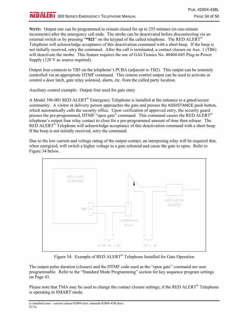
Output four connects to TB5 on the telephone’s PCBA (adjacent to TB2). This output can be remotely controlled via an appropriate DTMF command. This remote control output can be used to activate or control a door latch, gate relay solenoid, alarm, etc. from the called party location.
Auxiliary control example: Output four used for gate entry
A Model 396-001 RED ALERT® Emergency Telephone is installed at the entrance to a gated/secure community. A visitor or delivery person approaches the gate and presses the ASSISTANCE push button, which automatically calls the security office. Upon verification of approved entry, the security guard presses the pre-programmed, DTMF “open gate” command. This command causes the RED ALERT® telephone’s output four relay contact to close for a pre-programmed amount of time then release. The RED ALERT® Telephone will acknowledge acceptance of this deactivation command with a short beep. If the beep is not initially received, retry the command.
Due to the low current and voltage rating of the output contact, an interposing relay will be required that, when energized, will switch a higher voltage to a gate solenoid and cause the gate to open. Refer to Figure 34 below.
Figure 34. Example of RED ALERT® Telephone Installed for Gate Operation
The output pulse duration (closure) and the DTMF code used as the “open gate” command are user programmable. Refer to the “Standard Mode Programming” section for key sequence program settings on Page 43.
Please note that TMA may be used to change the contact closure settings, if the RED ALERT® Telephone is operating in SMART mode.

PUB. 42004-438L
300 SERIES EMERGENCY TELEPHONE MANUAL PAGE 35 of 50
p:\standard ioms - current release\42004 instr. manuals\42004-438l.docx 07/16
Standard Mode Programming
Prior to programming the RED ALERT® Telephones; read the “Programming Information” section in its
entirety, record the desired key sequences and jumper settings in the “User Settings” sections of Table 3
on Page 28 and Table 13 on Page 45, and then complete the programming as specified.
This “Programming” section has been divided into two distinct subsections; “Standard Mode” and
“SMART Mode”. Standard mode programming is used if the telephone system installation does not
include the TMA (Telephone Management Application) PC software. With TMA installed, the
telephones will be monitored and SMART Mode programming should be used. Normal telephone
operation is identical in either mode of operation.
Each RED ALERT® Telephone is factory-programmed to receive standard mode commands. Factory-
default settings are shown in Table 13 on Page 45.
Set-up Sequence
Set up each RED ALERT® Emergency Telephone for either “remote” access programming or for “local”
access programming (keypad required).
Remote
Using a touch-tone telephone, call the RED ALERT® Emergency Telephone. The emergency telephone
will automatically answer the call and generate a splash tone (low to high sequence), followed by a
success tone (short beep).
Local
1. RED ALERT® Telephones that do not include an integral keypad will require the use of a No. 51035-
011 Keypad and No. 61504-048 Keypad Cable Assembly. The keypad and cable must be connected
to J13 on the PCBA. Refer to Figure 32 for the location of J13.
2. The CALL push button connector J1 is exclusively used for local programming. RED ALERT®
telephones that include only the HELP push button must temporarily have the associated switch
harness plug moved from the HELP connector J7 to the CALL push button connector J1 on the PCBA.
3. Press the CALL or HELP push button (whichever is connected to J1). When the dial tone is heard
from the speaker, simultaneously press the “1” and “#” keypad buttons. The RED ALERT®
Telephone will generate a splash tone (low to high sequence), followed by a success tone (short
beep).

PUB. 42004-438L
300 SERIES EMERGENCY TELEPHONE MANUAL PAGE 36 of 50
p:\standard ioms - current release\42004 instr. manuals\42004-438l.docx 07/16
Programming Sequence
The following command sequences are common to both “remote” and “local” programming and are used
to configure the telephone to the desired operating parameters.
1. Dial the factory-default password 2468 (or appropriate customer-selected password). A success tone
(short beep) is generated to indicate that “standard” programming mode has been accessed.
2. After hearing the password success tone, begin entering each desired programming key sequence.
Refer to the “Programming Information” section on Page 36. A success tone (short beep) is
generated each time a new key sequence is accepted. An error tone (two low tones) is generated to
indicate an error. If an error tone is generated, verify the key sequence and enter the sequence again.
3. To terminate the programming call:
a. Remote – Place the programming telephone on hook. The RED ALERT® telephone will
automatically end the programming call within 20 seconds.
b. Local – Press the CALL or HELP push button (whichever is connected to J1) to end the call.
Restore any moved push-button harness connectors to their original position (if necessary).
NOTES:
1. The RED ALERT® telephone will automatically time out and disconnect if 20 seconds elapse
between digit entries, or if an invalid password is entered.
2. If DTMF digits have not been dialed within three seconds of the first success tone, the telephone will
exit programming mode and revert to a standard voice call.
3. If the password success tone is not generated, the telephone has failed to recognize the password. The
telephone must then be programmed with the password disabled. Refer to the next section,
“Password Disabled Programming”.
Password Disabled Programming
The programmable features of the RED ALERT® Emergency Telephones are protected by a factory
default or user specified password, as previously described. Situations may arise when a setting change is
required but the password is forgotten or unknown. To permit continued programming support in this
situation, converting to password disabled programming may be necessary and is described as follows:
1. Access the telephone’s PCBA and disable the password protection feature by changing jumper J9 to
the “DIS” position.
2. Confirm the auto-answer feature is enabled (jumper J14 should be in the “EN” position).
3. Using a touch-tone telephone, call the RED ALERT® Telephone. The telephone will automatically
answer the call and will generate a splash tone (low to high sequence) followed by a success tone
(single beep).
4. Begin entering the desired key sequences as previously described, following steps two and three in
the “Programming Sequence” section on Page 36.

PUB. 42004-438L
300 SERIES EMERGENCY TELEPHONE MANUAL PAGE 37 of 50
p:\standard ioms - current release\42004 instr. manuals\42004-438l.docx 07/16
Programming Information
The programming information on the following pages explains
the programming options. The telephone is shipped from the
factory with a set of default parameters that are listed in the
programming table on Page 45. A “User Settings” section has
been provided in the programming table for the user to record the
selected programming parameters.
Dialing Options
The emergency telephones can be configured for either auto-dialing or ring-down operation. Select the
dialing option that fits your application. The dialing options are explained in detail below.
Auto-dialing
The HELP push button can be programmed to call up to three unique telephone numbers. The unique
telephone numbers include a primary telephone number and two backup, or roll over, numbers. In the
event that an emergency call cannot connect to the primary telephone number (i.e., a busy signal or no
answer), the emergency telephone will automatically dial the first backup, or roll over, number. Again, in
the event that an emergency call cannot connect to the first back-up telephone number, the emergency
telephone will automatically dial the second backup, or roll over, number (if configured). This sequence
will continue until the emergency call is answered or all numbers have been attempted (one attempt each).
When operating in SMART mode, the number of attempts to call each programmed number can be
increased, as required, (two attempts each, three attempts each, etc.)
For the rollover feature to function properly in this mode, all three auto-dial memories must be
programmed with valid telephone numbers. The three auto-dial numbers can be the same or any
combination of telephone numbers. If the telephone is programmed with only one or two auto-dial
numbers, the rollover operation will not function and the numbers will only be dialed one time.
If an emergency telephone is connected to a PBX, PABX, KSU, etc., telephone system, the emergency
telephone can be programmed to access outside CO lines. Typically access to a CO line requires adding a
digit (e.g. 9) to the auto-dial number. Also, a “pause” may be required in the auto-dial number. The
pause typically is required to wait for the secondary (CO line) dial tone. See the example for the “Help
Button Auto-dial Number 1” in Table 4 on Page 38.
In addition to the pause, the emergency telephone has programmable “Primary Dial Tone Delay” and a
“Secondary Dial Tone Delay” capabilities. Both delays determine the amount of time that the emergency
telephone will wait before dialing the stored telephone number. The secondary dial tone delay can only
be used if a “9” is dialed to gain access to a CO line.
Programming Legend
D = DTMF digit 0–9, *, or #
N = Numeric digit 0–9
L = 0 - Disable, 1 - Enable

PUB. 42004-438L
300 SERIES EMERGENCY TELEPHONE MANUAL PAGE 38 of 50
p:\standard ioms - current release\42004 instr. manuals\42004-438l.docx 07/16
Ring-down Operation
Ring-down operation enables the telephone to go off-hook when the HELP push button is pressed. The
ring-down system must detect loop current and ring-down to the appropriate telephone.
Table 4. Auto-Dialing Key Sequence Setup
Feature
Key
Sequence Description Default
HELP Button
Auto-dial
Number 1
DD ... *1 Assigns a telephone number to the auto-dial memory 1. DD ...
represents the telephone number, which can be up to 24 digits in
length.
For access to an outside line, a pause may be required in the
telephone number to wait for secondary dial tone. The *#
represents a pause in the telephone number.
Examples:
To assign the police emergency number 911 to the auto-dial
button, enter 911*1.
To assign 911 when a “9” is required to gain access to a CO
line, enter 9*#911*1.
To store * or # as part of the auto-dial number, (such as for speed
dialing), enter these digits twice in succession.
None
HELP Button
Auto-dial
Number 2
DD ... *2 Same as HELP Button Auto-dial Number 1 except the sequence
ends in *2 instead of *1.
None
HELP Button
Auto-dial
Number 3
DD ... *3 Same as HELP Button Auto-dial Number 1 except the sequence
ends in *3 instead of *1.
None
CALL or
ASSISTANCE
Button Auto-dial
DD ... *4
DD ... *5
DD ... *6
Same as HELP Button Auto-dial Number 1 except the sequence
end digits.
None
Primary Dial
Tone Delay
# 1 0 N N The dial tone delay is the amount of time the unit waits for a dial
tone before auto-dialing the telephone number. (00* [20 seconds];
01–15 seconds).
Example: To wait up to 5 seconds for a dial tone, enter # 1 0 0 5.
*NOTE: If dial tone is not detected then autodialing does not
occur.
03 (3
seconds)
Secondary Dial
Tone Delay
# 1 1 N N This feature is only used if you must dial 9 to access an outside
line. It determines the amount of time (00–15 seconds) the
telephone waits for a second dial tone. The first programming
step indicated you must program 9*# and the number you want the
auto-dial to access. This programming parameter allows you to
choose the amount of time the telephone waits after sending the 9
and pausing before dialing the auto-dial number.
Example: To wait 10 seconds for the second dial tone, enter
# 1 1 1 0.
02 (2
seconds)
Ring-down
Operation
*1 This option clears the telephone number to prevent auto-dialing
when the button is pressed. After the button is pressed, the ring-
down system must detect loop current and ring-down to the
appropriate telephone.
None
PUB. 42004-438L
300 SERIES EMERGENCY TELEPHONE MANUAL PAGE 39 of 50
p:\standard ioms - current release\42004 instr. manuals\42004-438l.docx 07/16
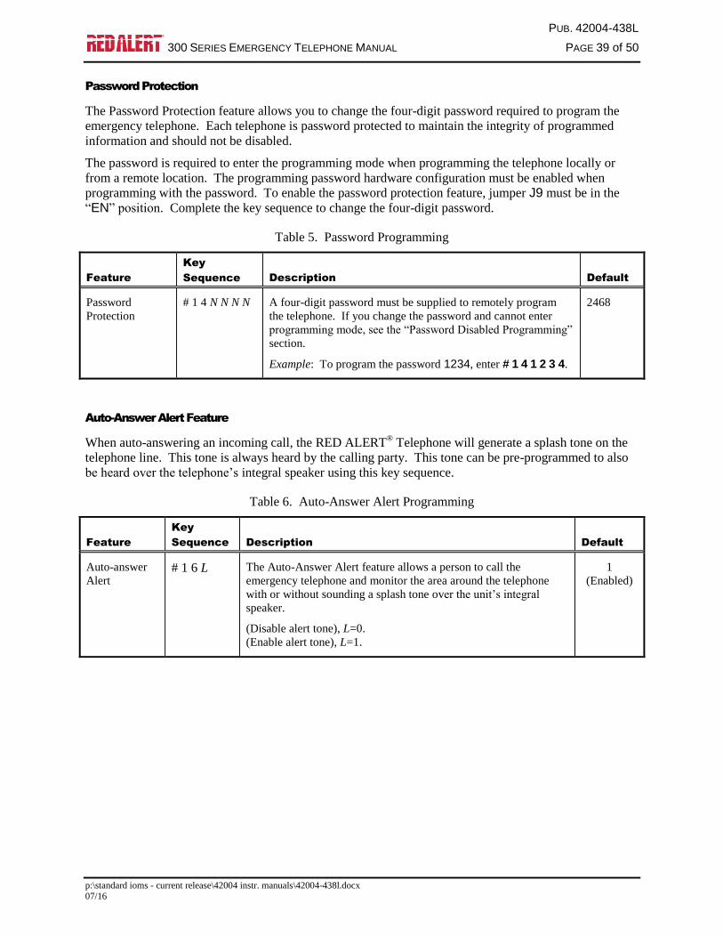
Password Protection
The Password Protection feature allows you to change the four-digit password required to program the
emergency telephone. Each telephone is password protected to maintain the integrity of programmed
information and should not be disabled.
The password is required to enter the programming mode when programming the telephone locally or
from a remote location. The programming password hardware configuration must be enabled when
programming with the password. To enable the password protection feature, jumper J9 must be in the
“EN” position. Complete the key sequence to change the four-digit password.
Table 5. Password Programming
Feature
Key
Sequence Description Default
Password
Protection
# 1 4 N N N N A four-digit password must be supplied to remotely program
the telephone. If you change the password and cannot enter
programming mode, see the “Password Disabled Programming”
section.
Example: To program the password 1234, enter # 1 4 1 2 3 4.
2468
Auto-Answer Alert Feature
When auto-answering an incoming call, the RED ALERT® Telephone will generate a splash tone on the
telephone line. This tone is always heard by the calling party. This tone can be pre-programmed to also
be heard over the telephone’s integral speaker using this key sequence.
Table 6. Auto-Answer Alert Programming
Feature
Key
Sequence Description Default
Auto-answer
Alert # 1 6 L The Auto-Answer Alert feature allows a person to call the
emergency telephone and monitor the area around the telephone
with or without sounding a splash tone over the unit’s integral
speaker.
(Disable alert tone), L=0.
(Enable alert tone), L=1.
1
(Enabled)

PUB. 42004-438L
300 SERIES EMERGENCY TELEPHONE MANUAL PAGE 40 of 50
p:\standard ioms - current release\42004 instr. manuals\42004-438l.docx 07/16
Off-Hook Ringing
The emergency telephone can generate a ringing signal from the speaker when the telephone is called.
The factory default setting for this feature is “disabled.”
NOTE: In addition to enabling this feature, the auto-answer feature must also be enabled for proper
operation.
Table 7. Off-Hook Ringing
Feature
Key
Sequence Description Default
Off-Hook
Ringing # 2 2 L Enabling the Off-Hook Ringing feature allows a person to call the
telephone and have the telephone function as a normal telephone.
The telephone will ring after the splash tone is heard in the receiver
if remote programming is not commenced within 7 seconds of the
splash tone.
To enable the ringing feature (enable splash tone and ringing), L=1.
To disable the ringing feature (only splash tone on the phone), L=0.
NOTE: Only RED ALERT® Telephones equipped with a CALL
push button can be answered when they are ringing by pressing the
push button.
0
(Disabled)
PUB. 42004-438L
300 SERIES EMERGENCY TELEPHONE MANUAL PAGE 41 of 50
p:\standard ioms - current release\42004 instr. manuals\42004-438l.docx 07/16
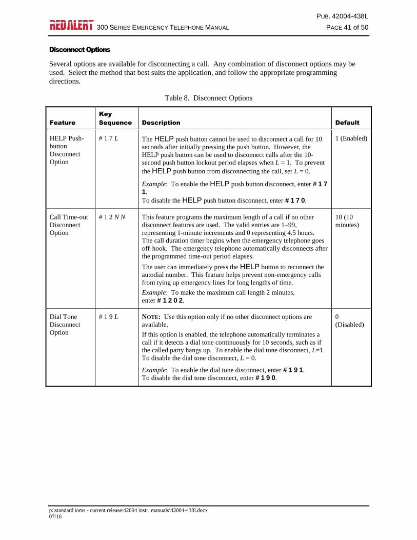
Disconnect Options
Several options are available for disconnecting a call. Any combination of disconnect options may be
used. Select the method that best suits the application, and follow the appropriate programming
directions.
Table 8. Disconnect Options
Feature
Key
Sequence Description Default
HELP Push-
button
Disconnect
Option
# 1 7 L The HELP push button cannot be used to disconnect a call for 10
seconds after initially pressing the push button. However, the
HELP push button can be used to disconnect calls after the 10-
second push button lockout period elapses when L = 1. To prevent
the HELP push button from disconnecting the call, set L = 0.
Example: To enable the HELP push button disconnect, enter # 1 7
1.
To disable the HELP push button disconnect, enter # 1 7 0.
1 (Enabled)
Call Time-out
Disconnect
Option
# 1 2 N N This feature programs the maximum length of a call if no other
disconnect features are used. The valid entries are 1–99,
representing 1-minute increments and 0 representing 4.5 hours.
The call duration timer begins when the emergency telephone goes
off-hook. The emergency telephone automatically disconnects after
the programmed time-out period elapses.
The user can immediately press the HELP button to reconnect the
autodial number. This feature helps prevent non-emergency calls
from tying up emergency lines for long lengths of time.
Example: To make the maximum call length 2 minutes,
enter # 1 2 0 2.
10 (10
minutes)
Dial Tone
Disconnect
Option
# 1 9 L NOTE: Use this option only if no other disconnect options are
available.
If this option is enabled, the telephone automatically terminates a
call if it detects a dial tone continuously for 10 seconds, such as if
the called party hangs up. To enable the dial tone disconnect, L=1.
To disable the dial tone disconnect, L = 0.
Example: To enable the dial tone disconnect, enter # 1 9 1.
To disable the dial tone disconnect, enter # 1 9 0.
0
(Disabled)
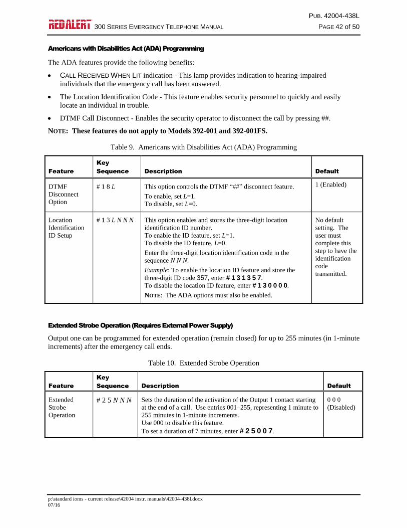
PUB. 42004-438L
300 SERIES EMERGENCY TELEPHONE MANUAL PAGE 42 of 50
p:\standard ioms - current release\42004 instr. manuals\42004-438l.docx 07/16
Americans with Disabilities Act (ADA) Programming
The ADA features provide the following benefits:
CALL RECEIVED WHEN LIT indication - This lamp provides indication to hearing-impaired
individuals that the emergency call has been answered.
The Location Identification Code - This feature enables security personnel to quickly and easily
locate an individual in trouble.
DTMF Call Disconnect - Enables the security operator to disconnect the call by pressing ##.
NOTE: These features do not apply to Models 392-001 and 392-001FS.
Table 9. Americans with Disabilities Act (ADA) Programming
Feature
Key
Sequence Description Default
DTMF
Disconnect
Option
# 1 8 L This option controls the DTMF “##” disconnect feature.
To enable, set L=1.
To disable, set L=0.
1 (Enabled)
Location
Identification
ID Setup
# 1 3 L N N N This option enables and stores the three-digit location
identification ID number.
To enable the ID feature, set L=1.
To disable the ID feature, L=0.
Enter the three-digit location identification code in the
sequence N N N.
Example: To enable the location ID feature and store the
three-digit ID code 357, enter # 1 3 1 3 5 7.
To disable the location ID feature, enter # 1 3 0 0 0 0.
NOTE: The ADA options must also be enabled.
No default
setting. The
user must
complete this
step to have the
identification
code
transmitted.
Extended Strobe Operation (Requires External Power Supply)
Output one can be programmed for extended operation (remain closed) for up to 255 minutes (in 1-minute
increments) after the emergency call ends.
Table 10. Extended Strobe Operation
Feature
Key
Sequence Description Default
Extended
Strobe
Operation
# 2 5 N N N Sets the duration of the activation of the Output 1 contact starting
at the end of a call. Use entries 001–255, representing 1 minute to
255 minutes in 1-minute increments.
Use 000 to disable this feature.
To set a duration of 7 minutes, enter # 2 5 0 0 7.
0 0 0
(Disabled)

PUB. 42004-438L
300 SERIES EMERGENCY TELEPHONE MANUAL PAGE 43 of 50
p:\standard ioms - current release\42004 instr. manuals\42004-438l.docx 07/16
Output 4 Control Setup
The command (DTMF key sequence) that triggers the timed activation of Output 4 contact closure (TB5)
is configurable. The sequence can contain up to eight DTMF digits in the 0–9 range. The first digit must
not be 0 (zero). Some examples of valid control sequences are: 87654321; 832; and even a single digit
such as 7. The duration of the activation (closure) of Output 4 can be set in the range of 0.1 to 12.7
seconds in 0.1-second increments.
Table 11. Output 4 Control Options
Feature
Key
Sequence Description Default
Control
Sequence
N N..* 8 Assigns the digits NN.. as the command key sequence that
triggers the timed activation of Output 4. NN is a sequence
of 1–8 digits, with the first digit not zero. To assign “726”
as the control sequence, enter 7 2 6 * 8.
90125
Duration of
Timed
Activation
# 2 6 N N N Sets the duration of the activation of the Output 4 contact
when triggered by the control sequence. Use entries 001–
127, representing 0.1 second to 12.7 seconds in
0.1-second increments.
Use 000 to disable this feature.
To set a duration of 7 seconds, enter # 2 6 0 7 0.
5 seconds
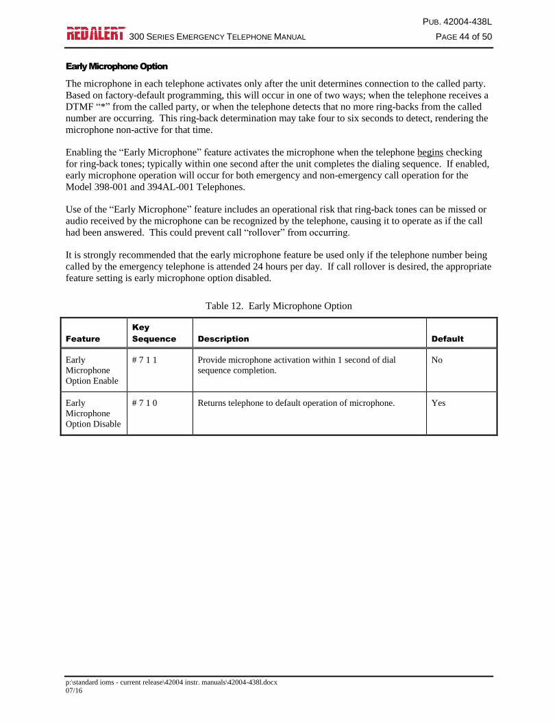
PUB. 42004-438L
300 SERIES EMERGENCY TELEPHONE MANUAL PAGE 44 of 50
p:\standard ioms - current release\42004 instr. manuals\42004-438l.docx 07/16
Early Microphone Option
The microphone in each telephone activates only after the unit determines connection to the called party.
Based on factory-default programming, this will occur in one of two ways; when the telephone receives a
DTMF “*” from the called party, or when the telephone detects that no more ring-backs from the called
number are occurring. This ring-back determination may take four to six seconds to detect, rendering the
microphone non-active for that time.
Enabling the “Early Microphone” feature activates the microphone when the telephone begins checking
for ring-back tones; typically within one second after the unit completes the dialing sequence. If enabled,
early microphone operation will occur for both emergency and non-emergency call operation for the
Model 398-001 and 394AL-001 Telephones.
Use of the “Early Microphone” feature includes an operational risk that ring-back tones can be missed or
audio received by the microphone can be recognized by the telephone, causing it to operate as if the call
had been answered. This could prevent call “rollover” from occurring.
It is strongly recommended that the early microphone feature be used only if the telephone number being
called by the emergency telephone is attended 24 hours per day. If call rollover is desired, the appropriate
feature setting is early microphone option disabled.
Table 12. Early Microphone Option
Feature
Key
Sequence Description Default
Early
Microphone
Option Enable
# 7 1 1 Provide microphone activation within 1 second of dial
sequence completion.
No
Early
Microphone
Option Disable
# 7 1 0 Returns telephone to default operation of microphone. Yes
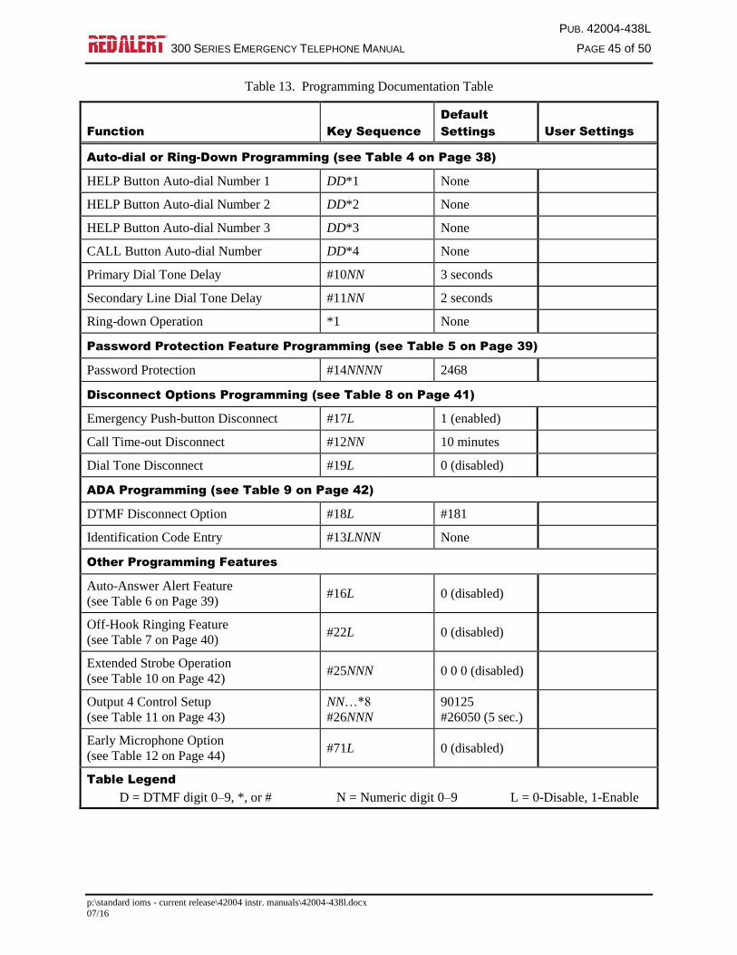
PUB. 42004-438L
300 SERIES EMERGENCY TELEPHONE MANUAL PAGE 45 of 50
p:\standard ioms - current release\42004 instr. manuals\42004-438l.docx 07/16
Table 13. Programming Documentation Table
Function Key Sequence
Default
Settings User Settings
Auto-dial or Ring-Down Programming (see Table 4 on Page 38)
HELP Button Auto-dial Number 1 DD*1 None
HELP Button Auto-dial Number 2 DD*2 None
HELP Button Auto-dial Number 3 DD*3 None
CALL Button Auto-dial Number DD*4 None
Primary Dial Tone Delay #10NN 3 seconds
Secondary Line Dial Tone Delay #11NN 2 seconds
Ring-down Operation *1 None
Password Protection Feature Programming (see Table 5 on Page 39)
Password Protection #14NNNN 2468
Disconnect Options Programming (see Table 8 on Page 41)
Emergency Push-button Disconnect #17L 1 (enabled)
Call Time-out Disconnect #12NN 10 minutes
Dial Tone Disconnect #19L 0 (disabled)
ADA Programming (see Table 9 on Page 42)
DTMF Disconnect Option #18L #181
Identification Code Entry #13LNNN None
Other Programming Features
Auto-Answer Alert Feature
(see Table 6 on Page 39) #16L 0 (disabled)
Off-Hook Ringing Feature
(see Table 7 on Page 40) #22L 0 (disabled)
Extended Strobe Operation
(see Table 10 on Page 42) #25NNN 0 0 0 (disabled)
Output 4 Control Setup
(see Table 11 on Page 43)
NN…*8
#26NNN
90125
#26050 (5 sec.)
Early Microphone Option
(see Table 12 on Page 44) #71L 0 (disabled)
Table Legend
D = DTMF digit 0–9, *, or # N = Numeric digit 0–9 L = 0-Disable, 1-Enable
PUB. 42004-438L
300 SERIES EMERGENCY TELEPHONE MANUAL PAGE 46 of 50
p:\standard ioms - current release\42004 instr. manuals\42004-438l.docx 07/16
SMART Mode Programming
TMA Software is designed to remotely program RED ALERT® Telephones for SMART mode operation.
Although they can be locally programmed for SMART operation, there is no advantage to having a RED
ALERT® Telephone set up for SMART mode without having TMA installed.
RED ALERT® Telephones installed in systems that will have TMA operational at a later date are
recommended to be programmed for standard mode operation. Upon installation of TMA, the installed
telephones can be reprogrammed from the TMA PC.
Maintenance
Battery Replacement (Voice Annunciation Option Only)
CAUTION Risk of explosion if battery is replaced by an incorrect type, or is incorrectly
replaced. Dispose of used batteries according to the instructions.
Replace with lithium “AA” batteries to ensure proper cold weather operation and maximum battery life.
Service
If your RED ALERT® Telephone requires depot repair service, contact your GAI-Tronics Regional
Service Center for a return authorization number (RA#). Equipment should be shipped prepaid to GAI-
Tronics with a return authorization number and a purchase order number. If the equipment is under
warranty, repairs will be made without charge. Please include a written explanation of all defects to assist
our technicians in their troubleshooting efforts.
Call 800-492-1212 inside the USA or 610-777-1374 outside the USA for help identifying the Regional
Service Center closest to you.
Preventive Maintenance for Model 392-001, 392-001FS, 396-00X, 396-
001FS, 397-00x, 397-001FS, and 398-00x Telephones.
Stainless steel does not normally require maintenance to prevent corrosion from occurring. Different
installation locations may require more regular maintenance than others, depending on the environment
and exposure to airborne contaminants. The following maintenance steps should be performed on a
regular basis or when corrosion is first noticed on your telephone.
Cleaning
For general cleaning, wipe the surface with a cleanser or a cleanser and water mixture. Any cleanser
that is safe for glass is usually safe for stainless steel. Wipe dry.
If corrosion or rusting is noticed, remove with a non-abrasive commercial cleanser and water. Rub
stained areas in the same direction as the existing grain. Stubborn stains may be removed with a
magnesium oxide, ammonia, and water paste. Wipe clean, rinse with water, and dry.
Corrosion Prevention
Automotive wax provides the best results in preventing corrosion on stainless steel. Simply apply wax,
let dry to a haze, and buff to a shine with a clean dry cloth. This application should protect the telephone
surface for many months as it will allow natural reformation of the chromium oxide layer.
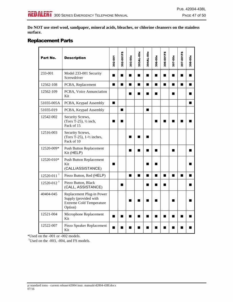
PUB. 42004-438L
300 SERIES EMERGENCY TELEPHONE MANUAL PAGE 47 of 50
p:\standard ioms - current release\42004 instr. manuals\42004-438l.docx 07/16
Do NOT use steel wool, sandpaper, mineral acids, bleaches, or chlorine cleansers on the stainless
surface.
Replacement Parts
Part No. Description
39
2-0
01
39
2-0
01
FS
39
3-0
0x
39
3A
L-0
0x
39
4A
L-0
0x
39
6-0
0x
39
6-0
01
FS
39
7-0
0x
39
7-0
01
FS
39
8-0
0x
233-001 Model 233-001 Security
Screwdriver
12562-108 PCBA, Replacement
12562-109 PCBA, Voice Annunciation
Kit
51035-005A PCBA, Keypad Assembly
51035-019 PCBA, Keypad Assembly
12542-002 Security Screws,
(Torx T-25), ½ inch,
Pack of 15
12516-003 Security Screws,
(Torx T-25), 1-½ inches,
Pack of 10
12520-009* Push Button Replacement
Kit (HELP)
12520-010* Push Button Replacement
Kit
(CALL/ASSISTANCE)
12520-011† Piezo Button, Red (HELP)
12520-012† Piezo Button, Black
(CALL, ASSISTANCE)
40404-045 Replacement Plug-in Power
Supply (provided with
Extreme Cold Temperature
Option)
12521-004 Microphone Replacement
Kit
12522-007 Piezo Speaker Replacement
Kit
*Used on the -001 or -002 models.
†Used on the -003, -004, and FS models.

PUB. 42004-438L
300 SERIES EMERGENCY TELEPHONE MANUAL PAGE 48 of 50
p:\standard ioms - current release\42004 instr. manuals\42004-438l.docx 07/16
Specifications
TMA compatibility profile type .............................................................. Type A Hands-free (RED ALERT)
Auto-dial digit limit .......................................................................................................................... 24 digits
Electrical
Audio output ................................................... 1 kHz tone – 87 ±3 dB SPL @ 1 m with 40 mA loop current
Battery voltage (tip and ring) ............................................................................................ 24 V dc or 48 V dc
Phone line requirements ............................................................................ Loop start, central office (CO), or
Analog station port (PBX, PABX, or KSU)
Minimum loop current ................................................................................... 24 mA (35 mA recommended)
Auxiliary output (Isolated solid state switch) ................................................................... 125 mA at 48 V dc
80 mA at 28 V ac
Signaling .......................................................................................................................... DTMF 100 ms tone
Memory ...................................................................................................................... Non-volatile EEPROM
Mechanical
Operating temperature range
-003 and -004 Models .......................................................................... −40 ºF to +140 ºF (−40 ºC to +60 ºC)
-001 and -002 Models ............................................................................ −4 ºF to +140 ºF (−20 ºC to +60 ºC)
Relative humidity ..................................................................................................... to 95%, non-condensing
Model 393-00x
Enclosure construction .................... Valox® (high impact, glass-reinforced polyester) painted safety yellow
Dimensions ............................................................... 9.5 H × 8.0 W × 4.0 D in (241.3 × 203.2 × 101.6 mm)
Weight ...................................................................................................................................... 4.0 lb (1.8 kg)
Models 393AL-00x and 394AL-00x
Enclosure construction ......................................................................... Cast aluminum painted safety yellow
Key Pad (Model 394AL-00x only) ............................................................................. Chrome-plated zinc
Dimensions ............................................................... 9.5 H × 8.0 W × 4.0 D in (241.3 × 203.2 × 101.6 mm)
Weight
Model 393AL-00x ............................................................................................................ 7.8 lb (3.5 kg)
Model 394AL-00x ............................................................................................................ 8.5 lb (3.8 kg)

PUB. 42004-438L
300 SERIES EMERGENCY TELEPHONE MANUAL PAGE 49 of 50
p:\standard ioms - current release\42004 instr. manuals\42004-438l.docx 07/16
Models 392-001, 396-00x, 397-00x, 397-00xxx, 398-00x, and 398-00xxx
Construction
Panel ...................................................................................... 14-gauge, type 304 brushed stainless steel
Back box ........................................................ 16-gauge cold-rolled steel with black polyurethane finish
Key Pad (Models 398-00x and 392-001 only)........................................................... Chrome-plated zinc
Dimensions
Front panel .................................................................................. 12.00 H × 10.00 W in (305 × 254 mm)
Back box (overall) .............................................. 10.06 H × 8.43 W × 2.50 D in (256 × 214 × 63.5 mm)
Cutout for mounting back box ...................................................... 10.13 H × 7.63 W in (257 × 194 mm)
Weight
Model 392-001 .................................................................................................................. 7.2 lb (3.3 kg)
Model 396-00x .................................................................................................................. 6.5 lb (2.9 kg)
Model 397-00x .................................................................................................................. 6.5 lb (2.9 kg)
Model 398-00x .................................................................................................................. 7.2 lb (3.3 kg)
Models 392-001FS, 396-001FS, and 397-001FS
Construction
Panel ...................................................................................... 14-gauge, type 304 brushed stainless steel
Back box ........................................................ 16-gauge cold-rolled steel with black polyurethane finish
Key Pad (Model 392-001FS only) ............................................................................ Chrome-plated zinc
Dimensions
Front panel ....................................................................................... 8.5 H × 6.5 W in (215 × 165.1 mm)
Back box (overall) .......................................... 7.62 H × 5.62 W × 2.37 D in (193.6 × 142.7 × 60.2 mm)
Cutout for flush mounting ........................................................ 7.75 H × 5.75 W in (196.9 × 146.1 mm)
Weight ......................................................................................................................................... 5 lb (2.3 kg)
Code Blue Retrofit Phones
Dimensions ..................................................................... 11.75 × 8.50 × 2.68 in (298.5 × 215.9 × 68.1 mm)
Weight
Model 397-00xCB ............................................................................................................. 6.0 lb (2.7 kg)
Model 398-00xCB ............................................................................................................. 6.7 lb (3.0 kg)
Ramtel Retrofit Phones
Dimensions ..................................................................... 11.88 × 8.25 × 2.68 in (301.6 × 209.6 × 68.1 mm)
Weight
Model 397-00xRT ............................................................................................................. 6.0 lb (2.7 kg)
Model 398-00xRT ............................................................................................................. 6.7 lb (3.0 kg)
Talk-A-Phone Retrofit Phones
Dimensions ....................................................................... 11.75 × 9.5 × 3.20 in (298.5 × 241.3 × 81.3 mm)
Weight
Model 397-00xTP .............................................................................................................. 6.0 lb (2.7 kg)
Model 398-00xTP .............................................................................................................. 6.7 lb (3.0 kg)

PUB. 42004-438L
300 SERIES EMERGENCY TELEPHONE MANUAL PAGE 50 of 50
p:\standard ioms - current release\42004 instr. manuals\42004-438l.docx 07/16
Approval Standards
Safety of Information Technology Equipment ...................................................................... UL/CSA 60950
Enclosures for Electrical Equipment ................................................................................................. Type 3R
47 CFR Part 68
Certification Number ........................................................................................... US: ADGTE05BGTC2010
Ringer Equivalence Number .......................................................................................................................5B
Network connection (USOC) .................................................................................................................. RJ11
IC Information (Canada)
IC Certification Number ....................................................................................................... 822B-GTC2010
Ringer Equivalence Number .......................................................................................................................5B
Connection Method ............................................................................................................................. CA11A
User Instructions (USA)
This equipment complies with Part 68 of the FCC rules and the requirements adopted by the ACTA. On this
equipment is a label that contains, among other information, a product identifier in the format
US:AAAEQ##TXXXX. If requested, this number must be provided to the telephone company.
User Instructions (Canada) CP-01, Issue 8, Part I: Section 14.1
NOTICE: The Industry Canada label identifies certified equipment. This certification means that the equipment
meets certain telecommunications network protective, operational and safety requirements as prescribed in the
appropriate Terminal Equipment Technical Requirements document (s). The Department does not guarantee the
equipment will operate to the user's satisfaction. Before installing this equipment, users should ensure that it is
permissible to be connected to the facilities of the local telecommunications company. The equipment must also be
installed using an acceptable method of connection. The customer should be aware that compliance with the above
conditions may not prevent degradation of service in some situations. Repairs to certified equipment should be
coordinated by a representative designated by the supplier. Any repairs or alterations made by the user to this
equipment, or equipment malfunctions, may give the telecommunications company cause to request the user to
disconnect the equipment. Users should ensure for their own protection that the electrical ground connections of the
power utility, telephone lines and internal metallic water pipe system, if present, are connected together. This
precaution may be particularly important in rural areas.
CP-01, Issue 8, Part I: Section 14.2
NOTICE: The Ringer Equivalence Number (REN) assigned to each terminal device provides an indication of the
maximum number of terminals allowed to be connected to a telephone interface. The termination on an interface
may consist of any combination of devices subject only to the requirement that the sum of the Ringer Equivalence
Numbers of all the devices does not exceed 5.
(Rev. 10/06)
WarrantyEquipment. GAI-Tronics warrants for a period of one (1) year from the date of shipment, that anyGAI-Tronics equipment supplied hereunder shall be free of defects in material and workmanship, shallcomply with the then-current product specifications and product literature, and if applicable, shall be fitfor the purpose specified in the agreed-upon quotation or proposal document. If (a) Seller’s goods proveto be defective in workmanship and/or material under normal and proper usage, or unfit for the purposespecified and agreed upon, and (b) Buyer’s claim is made within the warranty period set forth above,Buyer may return such goods to GAI-Tronics’ nearest depot repair facility, freight prepaid, at which timethey will be repaired or replaced, at Seller’s option, without charge to Buyer. Repair or replacement shallbe Buyer’s sole and exclusive remedy. The warranty period on any repaired or replacement equipmentshall be the greater of the ninety (90) day repair warranty or one (1) year from the date the originalequipment was shipped. In no event shall GAI-Tronics warranty obligations with respect to equipmentexceed 100% of the total cost of the equipment supplied hereunder. Buyer may also be entitled to themanufacturer’s warranty on any third-party goods supplied by GAI-Tronics hereunder. The applicabilityof any such third-party warranty will be determined by GAI-Tronics.
Services. Any services GAI-Tronics provides hereunder, whether directly or through subcontractors,shall be performed in accordance with the standard of care with which such services are normallyprovided in the industry. If the services fail to meet the applicable industry standard, GAI-Tronics willre-perform such services at no cost to buyer to correct said deficiency to Company's satisfaction providedany and all issues are identified prior to the demobilization of the Contractor’s personnel from the worksite. Re-performance of services shall be Buyer’s sole and exclusive remedy, and in no event shall GAI-Tronics warranty obligations with respect to services exceed 100% of the total cost of the servicesprovided hereunder.
Warranty Periods. Every claim by Buyer alleging a defect in the goods and/or services providedhereunder shall be deemed waived unless such claim is made in writing within the applicable warrantyperiods as set forth above. Provided, however, that if the defect complained of is latent and notdiscoverable within the above warranty periods, every claim arising on account of such latent defect shallbe deemed waived unless it is made in writing within a reasonable time after such latent defect is orshould have been discovered by Buyer.
Limitations / Exclusions. The warranties herein shall not apply to, and GAI-Tronics shall not beresponsible for, any damage to the goods or failure of the services supplied hereunder, to the extentcaused by Buyer’s neglect, failure to follow operational and maintenance procedures provided with theequipment, or the use of technicians not specifically authorized by GAI-Tronics to maintain or service theequipment. THE WARRANTIES AND REMEDIES CONTAINED HEREIN ARE IN LIEU OF ANDEXCLUDE ALL OTHER WARRANTIES AND REMEDIES, WHETHER EXPRESS OR IMPLIED BYOPERATION OF LAW OR OTHERWISE, INCLUDING ANY WARRANTIES OFMERCHANTABILITY OR FITNESS FOR A PARTICULAR PURPOSE.
Return PolicyIf the equipment requires service, contact your Regional Service Center for a return authorization number(RA#). Equipment should be shipped prepaid to GAI-Tronics with a return authorization number and apurchase order number. If the equipment is under warranty, repairs or a replacement will be made inaccordance with the warranty policy set forth above. Please include a written explanation of all defects toassist our technicians in their troubleshooting efforts.
Call 800-492-1212 (inside the USA) or 610-777-1374 (outside the USA) for help identifying theRegional Service Center closest to you.