Embed Size (px)
Citation preview
Reduce Generators Noise with Better Performance of a Diesel Generator Set using
Modified Absorption Silencer
Abstract- Noise pollution is considered to be one of the major environment pollutants which affect human beings both physically and psychologically, as such, a noise-free environment is in great demand worldwide. Diesel engine generators are highly appreciated as power sources of electric equipment in factories, houses and business centers. Loud sounds from diesel generators are a major cause of noise pollution. This paper analyzes the noise source of diesel generators and mitigates this pollution by a modified absorbance silencer or muffler. For automotive engines, the principle source of noise is its intake, radiator, combustion, etc. In our society, all of the industries, the residential sector and business plants use generators. In this research, an absorbance silencer is modified for reduced noise of the generator set. It is constructed from a combination of baffle or perforated duct with sheet metal. This paper aims to study the sound characteristics of generator sets and also aims to reduce the sound by means of a well-modified muffle silencer. This paper focuses on design and tests silencers, particularly absorption silencers for engine exhausts. Keywords: diesel engine; generator; absorption silencer; noise.
I. Introduction
ound pollution means unwanted sounds or noise. It is perceived by most people as annoying. Noise pollution harms most people’s lives. Additionally, it
is a great cause of environmental pollution. It greatly hampers humans not only physically, but mentally also. For these reasons, noise reduction is in great demand in this society, and noise prevention is a rising concern in all markets. In our society, all of the industries, the residential sector and business plants use generators. Diesel engine generators cause loud sounds.
A silencer is essential and an important part for sound attenuation of engine exhausts. There are many theories and designs of acoustic silencers of generator sets, developed in detail by Stewart theory and design of Acoustic and silencer of Generator set developed in detail by Stewart [1, 2] and he apply it to create many types of silencer and also success that explained in [2].
In 2013 Dr. Chazot, Nenning and Perry performed the method of unity finite element of 2D noise field with sound absorbing materials [3]. Now a days on top is a large company who designing, producing and manufacturing prefab modular flue and also distributing. It disposes of a modern product that certified ISO 9001 and also environment friendly as metaloterm lightweight silencer for flue system. In 2012, Mr. Ghosh, Bose and Chakraborty in india modified muffler and get a good performance of a diesel engine by used it [4]. The review of Generator set and silencer should be not complete without it mixed the effects of different absorption elements [5] .The diesel engine is the main noise sources of sound power also the generator exhaust and radiator fan [6], are measured by the method of sound intensity. At first May and Olson expressed an electronic noise absorber by pressure release on back face of resistive sheet [5]. Its introduce the notion of active absorption. Guicking and Lorenz in the year of 1980 fulfilled this theory and done experiment [7]. Various research have sought to complement multiple hybrid absorbance technique, leading to patent application [8]. In 1997 Mr. nail and Furstoss improved a layer of optical wool backed by air cavity closed through an active surface [9] by an active treatment. In the same year Beyene and Burdisso found active boundary condition [10]. They achieved it by impedance adaption means in layer of porous rear face.
But after the century in 2004 cobo et al. explained structure of thinner hybrid active and passive absorbers feasibility. He used micro perforated panels more than the porous materials[11]. The design mufflers and procedures are also in the literature (Munjal, 1987)[12]. Long time ago Stewart used electro acoustic analogies in deriving acoustic filters theory & design.[1]. After that Davis approach systematic studies result of muffler.[13]. Igarashi and M. Toyama calculated transmission characteristics by using electric circuit. [14, 15]. The last year in 2014 Babu, A.R Rao simulated a new muffler for reduce sound level of SI engine.[16]
In this paper, an absorbance silencer is modified for reduced noise of a generator set. It is constructed using a combination of baffle or perforated duct with sheet metal. The maximum generator has a simple silencer for reduction of the exhaust noise only. In this paper, a silencer is modified to reduce the noise
S
Gl oba
l Jo
urna
l of
Resea
rche
s in E
nginee
ring
(
)Volum
e X
VI Issue
I V
ersion
I
41
Year
2016
A
© 2016 Global Journals Inc. (US)
Author α ρ: Mechatronics Engineering, International Islamic University Malaysia. e-mail: [email protected] σ: Masters of Business Administration; FTMS Global Malaysia.e-mail: [email protected]Ѡ¥: Dhaka & Bhola polytechnic Institute, BTEB.e-mail: [email protected]
Md. Nasir Uddin α, Md Ahbabur Rahman σ, M. M. Rashid ρ, N A Nithe Ѡ & JI Rony¥
level and keep it at a minimum; also generators’ noise sources and their characteristics are discussed herein.
a) Method of Noise Measurement Noise means unwanted sounds that are
abnormal or loud- it is a relative term. Singing or hearing a song or musical instruments may be noise for some. Automotive engines create a large portion of the noise in our society. I.C engines are also a great source of sound pollution, as they are a powerful source of noise. The noise sources of both gasoline and diesel engines are the same, but their noise characteristics are different. Noise is highly subjective, and that which is irritating to one can be acceptable for another. To overcome this, noise is measured by a decibel (dB) meter in unit of dBs, withdB(A) representing the human ear’s sensitivity of 0 to 180 dB, where 0dB means no sound at all, and 180dB is a loud sound. An alternative explanation for 180 dB is the level of sound an atomic bomb would make upon explosion. The dB scale is a logarithmic meter. If d Bs risein in crements of 10, then the sound level rises 10 decade or 10 fold. If we know the level of noise source and maximum allowed level,
then it is easy to calculate the required sound reduction for the silencer. Alternatively, if the level of noise and the necessary noise reduction of silencer are known, then the remaining noise level can be easily calculated. Noise and sound have different frequencies. The unit of frequency is Hertz (Hz). Hertz means period per second, calculated by the equation f=1/t. We can hear from 20Hz to 20 kilohertz (20000Hz), but this depends on age. Machinery like engines, generators, vehicles and ventilators generally produce 50Hz to 3000Hz. The USA standard ASTM E413 describes frequencies of machinery as being in the range of 125 to 4000 Hz [17]. Similarly, The international standard ISO 717 refers to frequencies 100 to 3150 Hz[18]. The SI unit of sound reduction is dB and frequency is Hz[19]. But it is important to know that different frequencies demand different types of silencers
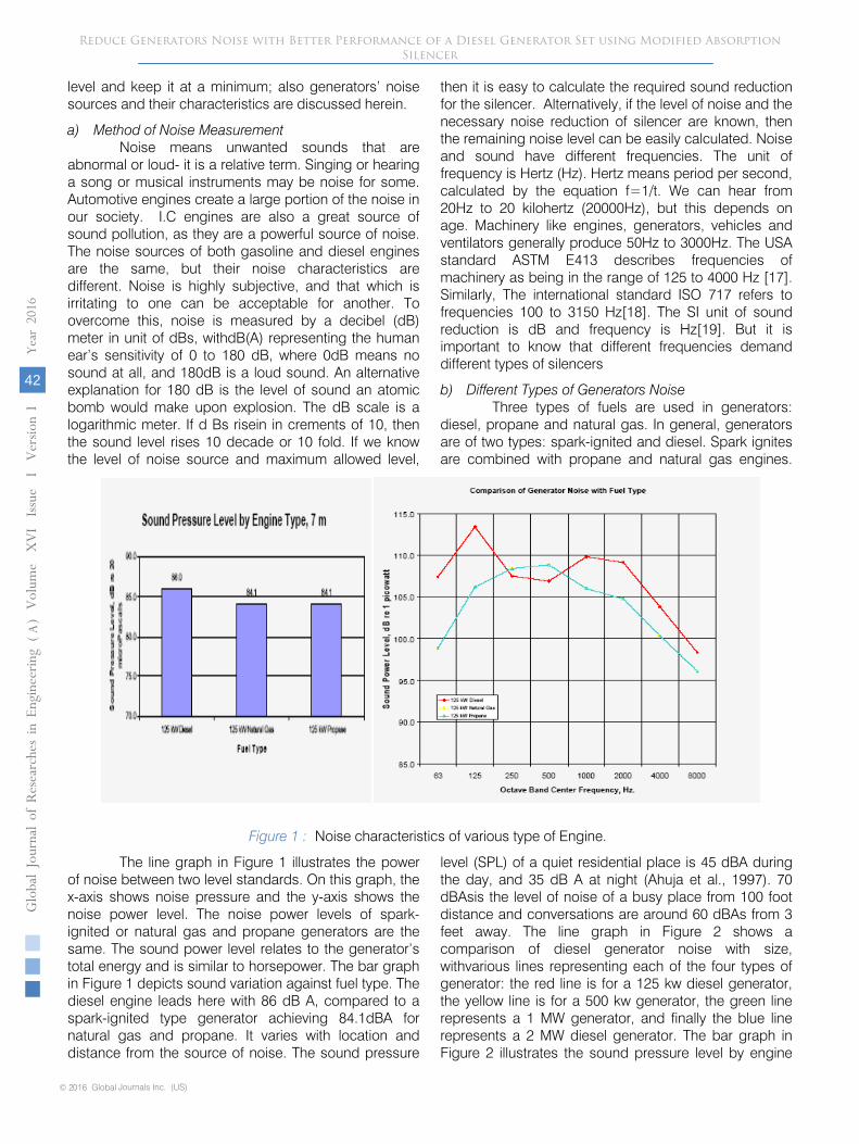
b) Different Types of Generators Noise Three types of fuels are used in generators:
diesel, propane and natural gas. In general, generators are of two types: spark-ignited and diesel. Spark ignites are combined with propane and natural gas engines.
Figure 1 : Noise characteristics of various type of Engine.
The line graph in Figure 1 illustrates the power of noise between two level standards. On this graph, the x-axis shows noise pressure and the y-axis shows the noise power level. The noise power levels of spark-ignited or natural gas and propane generators are the same. The sound power level relates to the generator’s total energy and is similar to horsepower. The bar graph in Figure 1 depicts sound variation against fuel type. The diesel engine leads here with 86 dB A, compared to a spark-ignited type generator achieving 84.1dBA for natural gas and propane. It varies with location and distance from the source of noise. The sound pressure
level (SPL) of a quiet residential place is 45 dBA during the day, and 35 dB A at night (Ahuja et al., 1997). 70 dBAsis the level of noise of a busy place from 100 foot distance and conversations are around 60 dBAs from 3 feet away. The line graph in Figure 2 shows a comparison of diesel generator noise with size, withvarious lines representing each of the four types of generator: the red line is for a 125 kw diesel generator, the yellow line is for a 500 kw generator, the green line represents a 1 MW generator, and finally the blue line represents a 2 MW diesel generator. The bar graph in Figure 2 illustrates the sound pressure level by engine
Reduce Generators Noise with Better Performance of a Diesel Generator Set using Modified Absorption Silencer
© 2016 Global Journals Inc. (US)
Globa
l Jo
urna
l of
Resea
rche
s in E
nginee
ring
(
)Volum
e X
VI Issue
I V
ersion
I
42
Year
2016
A
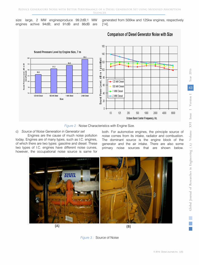
size: large, 2 MW enginesproduce 99.2dB;1 MW engines achive 94dB; and 91dB and 86dB are
generated from 500kw and 125kw engines, respectively [14].
Figure 2 : Noise Characteristics with Engine Size.
c)
Source of Noise Generation in Generator set Engines are the cause of much noise pollution
today. Engines are of many types, such as I.C. engines, of which there are two types: gasoline and diesel. These two types of I.C. engines have different noise curves, however, the occupational noise source is same for
both. For automotive engines, the principle source of noise comes from its intake, radiator and combustion. The dominant source is the engine block of the generator and the air intake. There are also some primary noise sources that are shown below.
Figure 3 : Source of Noise
Reduce Generators Noise with Better Performance of a Diesel Generator Set using Modified Absorption Silencer
Gl oba
l Jo
urna
l of
Resea
rche
s in E
nginee
ring
(
)Volum
e X
VI Issue
I V
ersion
I
43
Year
2016
A
© 2016 Global Journals Inc. (US)
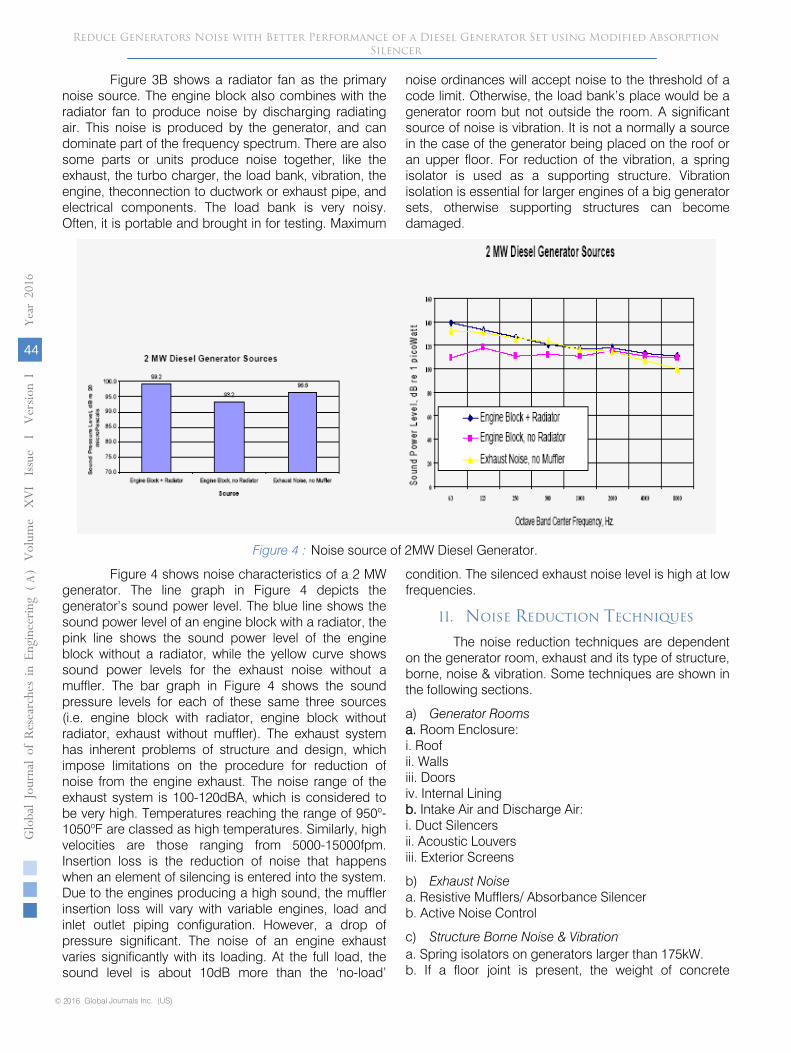
Figure 3B shows a radiator fan as the primary noise source. The engine block also combines with the radiator fan to produce noise by discharging radiating air. This noise is produced by the generator, and can dominate part of the frequency spectrum. There are also some parts or units produce noise together, like the exhaust, the turbo charger, the load bank, vibration, the engine, theconnection to ductwork or exhaust pipe, and electrical components. The load bank is very noisy. Often, it is portable and brought in for testing. Maximum
noise ordinances will accept noise to the threshold of a code limit. Otherwise, the load bank’s place would be a generator room but not outside the room. A significant source of noise is vibration. It is not a normally a source in the case of the generator being placed on the roof or an upper floor. For reduction of the vibration, a spring isolator is used as a supporting structure. Vibration isolation is essential for larger engines of a big generator sets, otherwise supporting structures can become damaged.
Figure 4 : Noise source of 2MW Diesel Generator.
Figure 4 shows noise characteristics of a 2 MW generator. The line graph in Figure 4 depicts the generator’s sound power level. The blue line shows the sound power level of an engine block with a radiator, the pink line shows the sound power level of the engine block without a radiator, while the yellow curve shows sound power levels for the exhaust noise without a muffler. The bar graph in Figure 4 shows the sound pressure levels for each of these same three sources (i.e. engine block with radiator, engine block without radiator, exhaust without muffler). The exhaust system has inherent problems of structure and design, which impose limitations on the procedure for reduction of noise from the engine exhaust. The noise range of the exhaust system is 100-120dBA, which is considered to be very high. Temperatures reaching the range of 950o-1050oF are classed as high temperatures. Similarly, high velocities are those ranging from 5000-15000fpm. Insertion loss is the reduction of noise that happens when an element of silencing is entered into the system. Due to the engines producing a high sound, the muffler insertion loss will vary with variable engines, load and inlet outlet piping configuration. However, a drop of pressure significant. The noise of an engine exhaust varies significantly with its loading. At the full load, the sound level is about 10dB more than the ‘no-load’
condition. The silenced exhaust noise level is high at low frequencies.
II. Noise Reduction Techniques
The noise reduction techniques are dependent on the generator room, exhaust and its type of structure, borne, noise & vibration. Some techniques are shown in the following sections.
a) Generator Rooms a. Room Enclosure: i. Roof ii. Walls iii. Doors iv. Internal Lining b. Intake Air and Discharge Air: i. Duct Silencers ii. Acoustic Louvers iii. Exterior Screens
b) Exhaust Noise a. Resistive Mufflers/ Absorbance Silencer b. Active Noise Control
c) Structure Borne Noise & Vibration a. Spring isolators on generators larger than 175kW. b. If a floor joint is present, the weight of concrete
Reduce Generators Noise with Better Performance of a Diesel Generator Set using Modified Absorption Silencer
© 2016 Global Journals Inc. (US)
Globa
l Jo
urna
l of
Resea
rche
s in E
nginee
ring
(
)Volum
e X
VI Issue
I V
ersion
I
44
Year
2016
A
beneath the generator should be not less than twice the generator weight. c. Flexible pipe connectors, duct connectors, electrical connection at the generator. Active noise cancellation silencers used to be available as amanu
factured product, but are not
currently available. They were effective in reducing the
low frequency tones associated with
the cylinder firing.
In this research paper, we design and modified resistive mufflers / absorbance silencers for reduction of exhaust noise.
III.
Methodology
The methodology involves silencer design and
development, and consists of some steps. After this, a modified silencer for use with a generator for a practical experiment is produced.
The properly designed muffler
for any particular application should satisfy the often –
conflicting demands of at least five criteria simultaneously.
a) Criterion and Flowchart of Methodology The acoustic criterion, which specifies the
minimum noise reduction, is required from the muffler as a function of frequency. The operating conditions must be known because large steady-flow velocities or large alternating velocities (high sound pressure levels) may alter its acoustic performance. The aerodynamic criterion specifies the maximum acceptable average pressure drop through the muffler at a given temperature and mass flow. The geometrical criterion specifies the maximum allowable volume and restrictions on shape. The mechanical criterion may specify materials that are durable and require little maintenance. The economical criterion is vital in the marketplace [33]
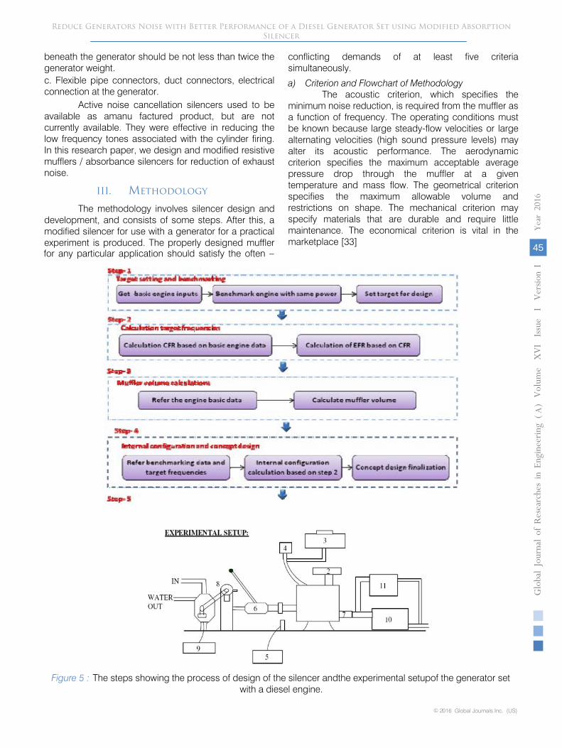
Figure 5 : The steps showing the process of design of the silencer andthe experimental setupof the generator set with a diesel engine.
Reduce Generators Noise with Better Performance of a Diesel Generator Set using Modified Absorption Silencer
Gl oba
l Jo
urna
l of
Resea
rche
s in E
nginee
ring
(
)Volum
e X
VI Issue
I V
ersion
I
45
Year
2016
A
© 2016 Global Journals Inc. (US)
1. Diesel Engine
2. Filter
3. Tank
4. Burret
5. RPM Indicator
6. Clatch or Shaft
7. Exhaust Outlet
8. Alternator
9. Radiator
10. Silencer
11. Sound Meter
The generator block diagram is replaced by the experimental setup block diagram. The various types of generator sets include
150KW, 350KW, 500KW, 1MW
and 2MW diesel engines for use during the experiment and data collection. The experimental silencer was designed for a 500KW diesel engine generator set, and the basic specifications of the generator set are given in Table 1.
Table 1 : Specifications of the generator set
SN Item Specification 1 Rating 635KVA 2 Power 508KW 3 Current 850A 4 Rated
revolution 1800RPM
5 Pressure 460KPA 6 cylinder 6 7 Cycle/stroke 4 8 Engine Load 75% and Full Load also
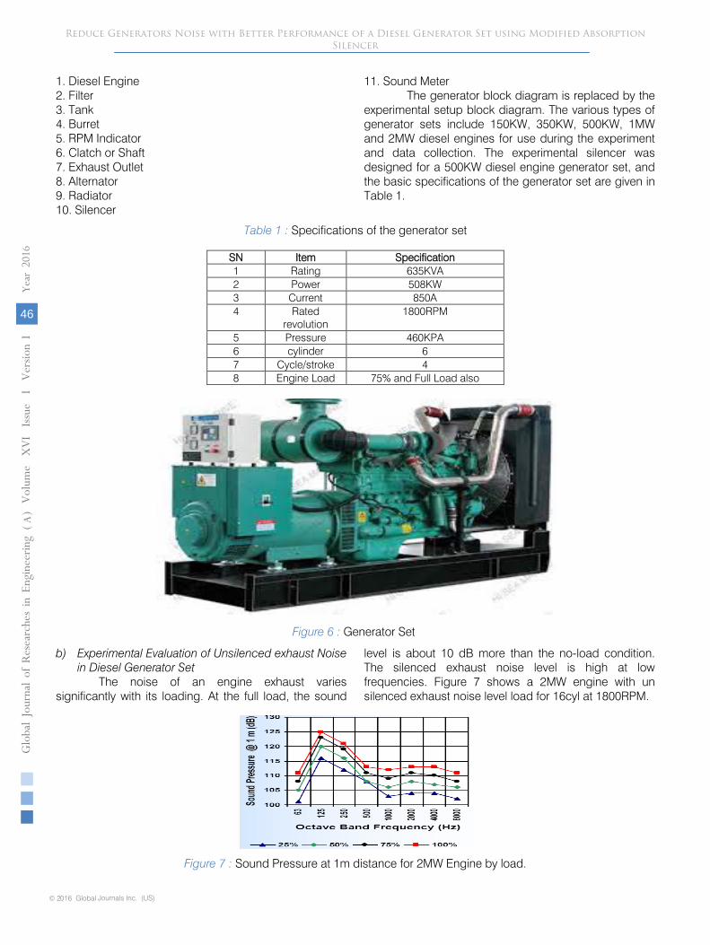
Figure 6 : Generator Set
b) Experimental Evaluation of Unsilenced exhaust Noise in Diesel Generator Set
The noise of an engine exhaust varies significantly with its loading. At the full load, the sound
level is about 10 dB more than the no-load condition. The silenced exhaust noise level is high at low frequencies. Figure 7 shows a 2MW engine with un
silenced exhaust noise level load for 16cyl at 1800RPM.
Figure 7 : Sound Pressure at 1m distance for 2MW Engine by load.
Reduce Generators Noise with Better Performance of a Diesel Generator Set using Modified Absorption Silencer
© 2016 Global Journals Inc. (US)
Globa
l Jo
urna
l of
Resea
rche
s in E
nginee
ring
()
Volum
e X
VI Issue
I V
ersion
I
46
Year
2016
A
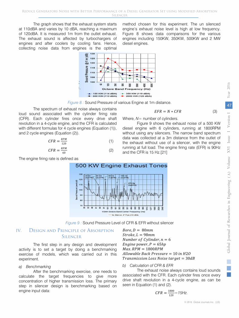
The graph shows that the exhaust system starts at 110dBA and varies by 10 dBA, reaching a maximum of 120dBA. It is measured 1m from the outlet exhaust. The exhaust sound is affected by turbochargers of engines and after coolers by cooling fans. Hence, collecting noise data from engines is the optimal
method chosen for this experiment. The un silenced engine’s exhaust noise level is high at low frequency. Figure 8 shows data comparisons for the various engines including 150KW, 350KW, 500KW and 2 MW diesel engines.
Figure 8 : Sound Pressure of various Engine at 1m distance.
The spectrum of exhaust noise always contains loud sound associated with the cylinder firing rate (CFR). Each cylinder fires once every drive shaft revolution in a 4-cycle engine, and the CFR is calculated with different formulas for 4 cycle engines (Equation (1)), and 2 cycle engines (Equation (2)).
𝐶𝐶𝐶𝐶𝐶𝐶 = 𝐶𝐶𝑅𝑅𝑅𝑅120
(1)
𝐶𝐶𝐶𝐶𝐶𝐶 = 𝐶𝐶𝑅𝑅𝑅𝑅60
(2)
The engine firing rate is defined as
𝐸𝐸𝐶𝐶𝐶𝐶 = 𝑁𝑁 ∗ 𝐶𝐶𝐶𝐶𝐶𝐶 (3)
Where, N= number of cylinders. Figure 9 shows the exhaust noise of a 500 KW
diesel engine with 6 cylinders, running at 1800RPM without using any silencers. The narrow band spectrum data was collected at a 3m distance from the outlet of the exhaust without use of a silencer, with the engine running at full load. The engine firing rate (EFR) is 90Hz and the CFR is 15 Hz.[21]
Figure 9 : Sound Pressure Level of CFR & EFR without silencer
IV.
Design and Principle of Absorption Silencer
The first step in any design and development activity is to set a target by doing a benchmarking exercise of models, which was carried out in this experiment. a) Benchmarking
After the benchmarking exercise, one needs to calculate the target frequencies to give more concentration of higher transmission loss. The primary step in silencer design is benchmarking based on engine input data:
𝐵𝐵𝐵𝐵𝐵𝐵𝐵𝐵,𝐷𝐷 = 80𝑚𝑚𝑚𝑚 𝑆𝑆𝑆𝑆𝐵𝐵𝐵𝐵𝑆𝑆𝐵𝐵, 𝐿𝐿 = 98𝑚𝑚𝑚𝑚 𝑁𝑁𝑁𝑁𝑚𝑚𝑁𝑁𝐵𝐵𝐵𝐵 𝐵𝐵𝑜𝑜 𝐶𝐶𝐶𝐶𝐶𝐶𝐶𝐶𝐶𝐶𝐶𝐶𝐵𝐵𝐵𝐵,𝐶𝐶 = 6 𝐸𝐸𝐶𝐶𝐸𝐸𝐶𝐶𝐶𝐶𝐵𝐵 𝑝𝑝𝐵𝐵𝑝𝑝𝐵𝐵𝐵𝐵,𝑅𝑅 = 65ℎ𝑝𝑝 𝑅𝑅𝑀𝑀𝑀𝑀.𝐶𝐶𝑅𝑅𝑅𝑅 = 1800𝐶𝐶𝑅𝑅𝑅𝑅 𝐴𝐴𝐶𝐶𝐶𝐶𝐵𝐵𝑝𝑝𝑀𝑀𝑁𝑁𝐶𝐶𝐵𝐵 𝐵𝐵𝑀𝑀𝐵𝐵𝑆𝑆 𝑅𝑅𝐵𝐵𝐵𝐵𝑃𝑃𝑃𝑃𝑁𝑁𝐵𝐵𝐵𝐵 = 10 𝐶𝐶𝐶𝐶 𝐻𝐻2𝑂𝑂 𝑇𝑇𝐵𝐵𝑀𝑀𝐶𝐶𝑃𝑃𝑚𝑚𝐶𝐶𝑃𝑃𝑃𝑃𝐶𝐶𝐵𝐵𝐶𝐶 𝐿𝐿𝐵𝐵𝑃𝑃𝑃𝑃 𝑁𝑁𝐵𝐵𝐶𝐶𝑃𝑃𝐵𝐵 𝑆𝑆𝑀𝑀𝐵𝐵𝐸𝐸𝐵𝐵𝑆𝑆 = 30𝐶𝐶𝐵𝐵
b) Calculation of CFR & EFR The exhaust noise always contains loud sounds
associated with the CFR. Each cylinder fires once every drive shaft revolution in a 4-cycle engine, as can be seen in Equation (1) and (2).
𝐶𝐶𝐶𝐶𝐶𝐶 = 1800120
=15Hz.
Reduce Generators Noise with Better Performance of a Diesel Generator Set using Modified Absorption Silencer
Gl oba
l Jo
urna
l of
Resea
rche
s in E
nginee
ring
(
)Volum
e X
VI Issue
I V
ersion
I
47
Year
2016
A
© 2016 Global Journals Inc. (US)
Engine Firing rate (using Equation (3)): 6*15=90Hz
c) Volume of the muffler (Vm) The volume of the muffler isdefined as Vm, with
units in litres. The calculation of the volume can be done using Equation (4):
𝑉𝑉𝑚𝑚 = 𝑉𝑉𝑜𝑜 ∗ 𝜋𝜋4
(𝐶𝐶2 ∗ 𝐶𝐶) ∗ (𝐶𝐶2) (4)
Swept volume per cylinder is calculated as follows:
𝑉𝑉𝑃𝑃 = 𝜋𝜋4
(𝐶𝐶2 ∗ 𝐶𝐶) = 3.14∗802∗984
= 0.5 Lit. (5)
Total n*Vs=6*0.5=3 Lit.
Volume, Vm=(n)*𝑉𝑉𝑃𝑃2
=1.5 Lit.
The silencer volume is considered to be at least 12 to 25 times larger, with a factor of 16
𝑆𝑆𝐶𝐶𝐶𝐶𝐵𝐵𝐶𝐶𝐵𝐵𝐵𝐵𝐵𝐵 𝑉𝑉𝐵𝐵𝐶𝐶𝑁𝑁𝑚𝑚𝐵𝐵 = 16 ∗ 1.5 = 24 𝐿𝐿𝐶𝐶𝑆𝑆.
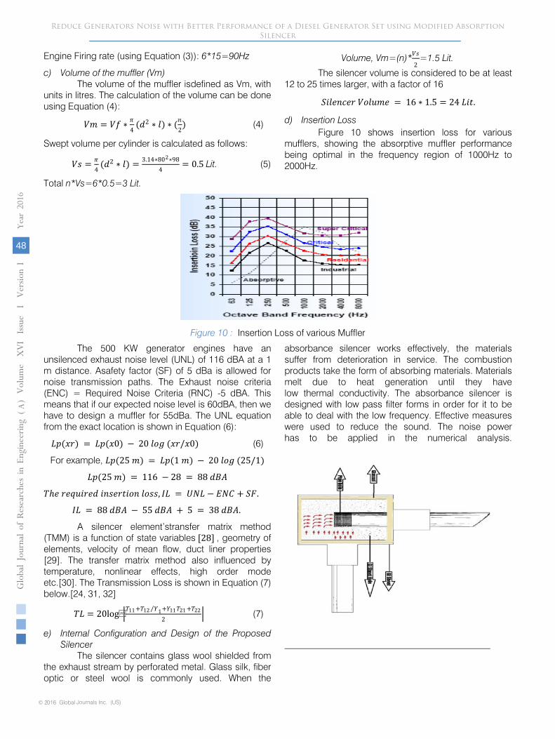
d) Insertion Loss
Figure 10 shows insertion loss for various mufflers, showing the absorptive muffler performance being optimal in the frequency region of 1000Hz to 2000Hz.
Figure 10 : Insertion Loss of various Muffler
The 500 KW generator engines have an unsilenced exhaust noise level (UNL) of 116 dBA at a 1 m distance. Asafety factor (SF) of 5 dBa is allowed for noise transmission paths. The Exhaust noise criteria (ENC) = Required Noise Criteria (RNC) -5 dBA. This means that if our expected noise level is 60dBA, then we have to design a muffler for 55dBa. The UNL equation from the exact location is shown in Equation (6):
𝐿𝐿𝑝𝑝(𝑀𝑀𝐵𝐵) = 𝐿𝐿𝑝𝑝(𝑀𝑀0) − 20 𝐶𝐶𝐵𝐵𝐸𝐸 (𝑀𝑀𝐵𝐵/𝑀𝑀0) (6)
For example, 𝐿𝐿𝑝𝑝(25 𝑚𝑚) = 𝐿𝐿𝑝𝑝(1 𝑚𝑚) − 20 𝐶𝐶𝐵𝐵𝐸𝐸 (25/1)
𝐿𝐿𝑝𝑝(25 𝑚𝑚) = 116 − 28 = 88 𝐶𝐶𝐵𝐵𝐴𝐴
𝑇𝑇ℎ𝐵𝐵 𝐵𝐵𝐵𝐵𝑟𝑟𝑁𝑁𝐶𝐶𝐵𝐵𝐵𝐵𝐶𝐶 𝐶𝐶𝐶𝐶𝑃𝑃𝐵𝐵𝐵𝐵𝑆𝑆𝐶𝐶𝐵𝐵𝐶𝐶 𝐶𝐶𝐵𝐵𝑃𝑃𝑃𝑃, 𝐼𝐼𝐿𝐿 = 𝑈𝑈𝑁𝑁𝐿𝐿 − 𝐸𝐸𝑁𝑁𝐶𝐶 + 𝑆𝑆𝐶𝐶.
𝐼𝐼𝐿𝐿 = 88 𝐶𝐶𝐵𝐵𝐴𝐴 − 55 𝐶𝐶𝐵𝐵𝐴𝐴 + 5 = 38 𝐶𝐶𝐵𝐵𝐴𝐴.
A silencer element’stransfer matrix method (TMM) is a function of state variables [28] , geometry of elements, velocity of mean flow, duct liner properties [29]. The transfer matrix method also influenced by temperature, nonlinear effects, high order mode etc.[30]. The Transmission Loss is shown in Equation (7) below.[24, 31, 32]
𝑇𝑇𝐿𝐿 = 20log�𝑇𝑇11 +𝑇𝑇12 𝑌𝑌⁄ 1+𝑌𝑌11𝑇𝑇21 +𝑇𝑇222
� (7)
e) Internal Configuration and Design of the Proposed Silencer
The silencer contains glass wool shielded from the exhaust stream by perforated metal. Glass silk, fiber optic or steel wool is commonly used. When the
absorbance silencer works effectively, the materials suffer from deterioration in service. The combustion products take the form of absorbing materials. Materials melt due to heat generation until they have low thermal conductivity. The absorbance silencer is designed with low pass filter forms in order for it to be able to deal with the low frequency. Effective measures were used to reduce the sound. The noise power has to be applied in the numerical analysis.
Reduce Generators Noise with Better Performance of a Diesel Generator Set using Modified Absorption Silencer
© 2016 Global Journals Inc. (US)
Globa
l Jo
urna
l of
Resea
rche
s in E
nginee
ring
(
)Volum
e X
VI Issue
I V
ersion
I
48
Year
2016
A
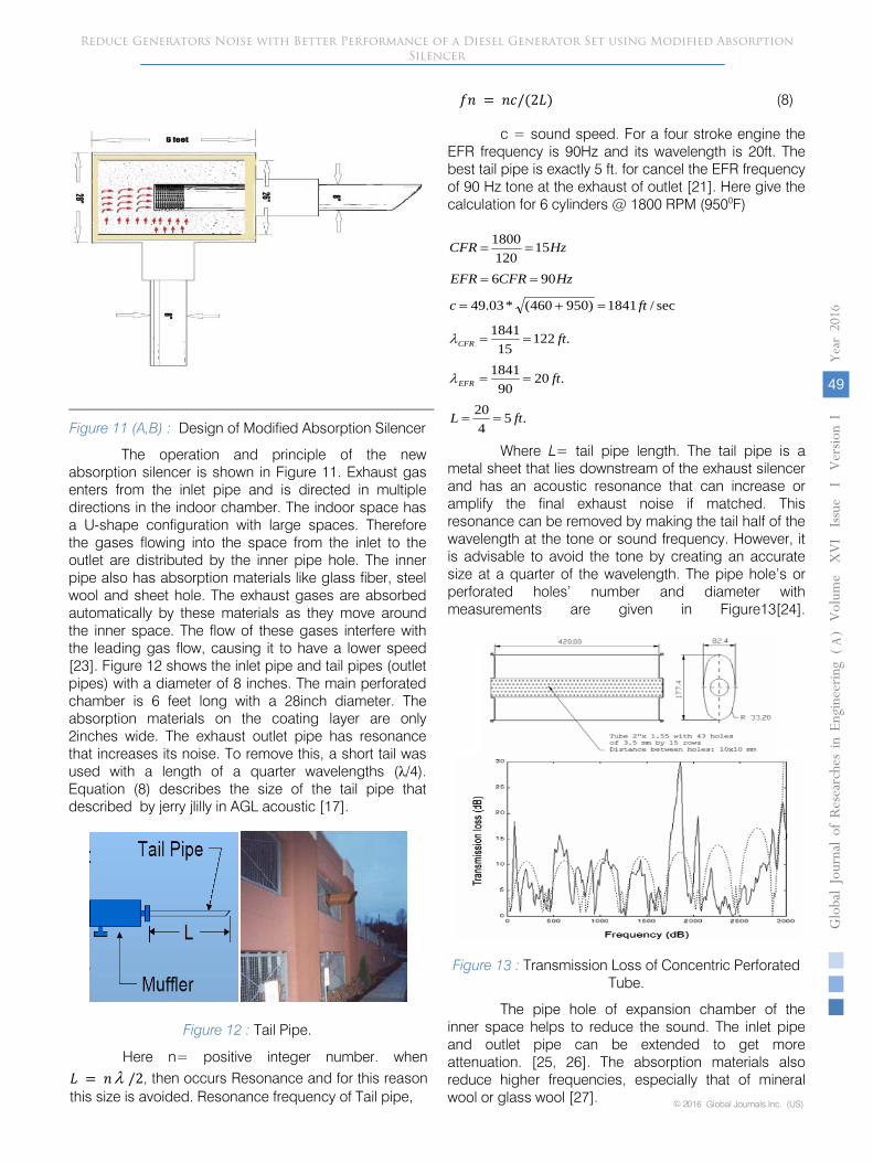
Figure 11
(A,B) : Design of Modified Absorption Silencer
The operation and principle of the new absorption silencer is shown in Figure 11. Exhaust gas enters from the inlet pipe and is directed in multiple directions in the indoor chamber. The indoor space has a U-shape configuration with large spaces. Therefore the gases flowing into the space from the inlet to the outlet are distributed by the inner pipe hole. The inner pipe also has absorption materials like glass fiber, steel wool and sheet hole. The exhaust gases are absorbed automatically by these materials as they move around the inner space. The flow of these gases interfere with the leading gas flow, causing it to have a lower speed [23]. Figure 12 shows the inlet pipe and tail pipes (outlet pipes) with a diameter of 8 inches. The main perforated chamber is 6 feet long with a 28inch diameter. The absorption materials on the coating layer are only 2inches wide. The exhaust outlet pipe has resonance that increases its noise.
To remove this,
a short tail was used with a length of a quarter wavelengths (λ/4). Equation (8) describes the size of the tail pipe that described by jerry jlilly in AGL acoustic [17].
Figure 12 :
Tail Pipe.
Here n= positive integer number. when 𝐿𝐿 = 𝐶𝐶λ /2, then occurs Resonance and for this reason this size is avoided. Resonance frequency of Tail pipe,
𝑜𝑜𝐶𝐶 = 𝐶𝐶𝐵𝐵/(2𝐿𝐿) (8)
c = sound speed. For a four stroke engine the EFR frequency is 90Hz and its wavelength is 20ft. The best tail pipe is exactly 5 ft. for cancel the EFR frequency of 90 Hz tone at the exhaust of outlet [21]. Here give the calculation
for 6 cylinders @ 1800 RPM (9500F)
.5420
.2090
1841
.12215
1841
sec/1841)950460(*03.49
906
15120
1800
ftL
ft
ft
ftc
HzCFREFR
HzCFR
EFR
CFR
==
==
==
=+=
==
==
λ
λ
Where L= tail pipe length. The tail pipe is a metal sheet that lies downstream of the exhaust silencer and has an acoustic resonance that can increase or amplify the final exhaust noise if matched. This resonance can be removed by making the tail half of the wavelength at the tone or sound frequency. However, it is advisable to avoid the tone by creating an accurate size at a quarter of the wavelength. The pipe hole’s or perforated holes’ number and diameter with measurements
are given in Figure13[24].
Figure 13 :
Transmission Loss of Concentric Perforated Tube.
The pipe hole of expansion chamber of the inner space helps to reduce the sound. The inlet pipe and outlet pipe can be extended to get more attenuation. [25, 26]. The absorption materials also reduce higher frequencies, especially that of mineral wool or glass wool [27].
Reduce Generators Noise with Better Performance of a Diesel Generator Set using Modified Absorption Silencer
Gl oba
l Jo
urna
l of
Resea
rche
s in E
nginee
ring
(
)Volum
e X
VI Issue
I V
ersion
I
49
Year
2016
A
© 2016 Global Journals Inc. (US)
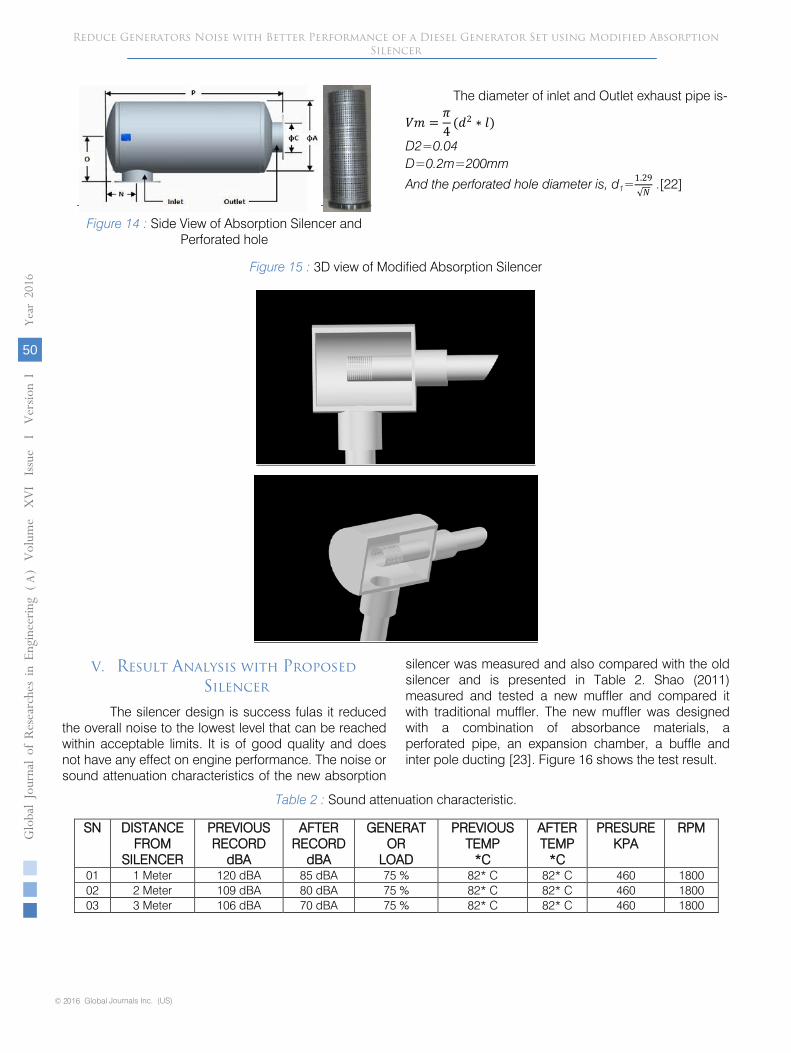
Figure 14 : Side View of Absorption Silencer and Perforated hole
The diameter of inlet and Outlet exhaust pipe is-
𝑉𝑉𝑚𝑚 =𝜋𝜋4
(𝐶𝐶2 ∗ 𝐶𝐶)
D2=0.04
D=0.2m=200mm
And the perforated hole diameter is, d1=1.29√𝑁𝑁
.[22]
Figure 15 : 3D view of Modified Absorption Silencer
V.
Result Analysis with Proposed Silencer
The silencer design is success fulas it reduced
the overall noise to the lowest level that can be reached
within acceptable limits. It is of good quality and does not have any effect on engine performance. The noise or sound attenuation characteristics of the new absorption
silencer was measured and also compared with the old
silencer and is presented in Table 2. Shao (2011) measured and tested a new muffler and compared it with traditional muffler. The new muffler was designed with a combination of absorbance materials, a perforated pipe, an expansion chamber, a buffle and inter
pole ducting [23]. Figure 16 shows the test result.
Table 2 : Sound attenuation characteristic.
SN
DISTANCE FROM
SILENCER
PREVIOUS
RECORD dBA
AFTER
RECORD dBA
GENERATOR
LOAD
PREVIOUS
TEMP
*C
AFTER
TEMP
*C
PRESURE
KPA
RPM
01
1 Meter
120 dBA
85 dBA
75 %
82* C
82* C
460
1800
02
2 Meter
109 dBA
80 dBA
75 %
82* C
82* C
460
1800
03
3 Meter
106 dBA
70 dBA
75 %
82* C
82* C
460
1800
Reduce Generators Noise with Better Performance of a Diesel Generator Set using Modified Absorption Silencer
© 2016 Global Journals Inc. (US)
Globa
l Jo
urna
l of
Resea
rche
s in E
nginee
ring
(
)Volum
e X
VI Issue
I V
ersion
I
50
Year
2016
A
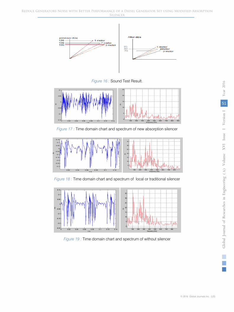
Figure 16 : Sound Test Result.
Figure 17 : Time domain chart and spectrum of new absorption silencer
Figure 18 : Time domain chart and spectrum of local or traditional silencer
Figure 19 : Time domain chart and spectrum of without silencer
Reduce Generators Noise with Better Performance of a Diesel Generator Set using Modified Absorption Silencer
Gl oba
l Jo
urna
l of
Resea
rche
s in E
nginee
ring
(
)Volum
e X
VI Issue
I V
ersion
I
51
Year
2016
A
© 2016 Global Journals Inc. (US)
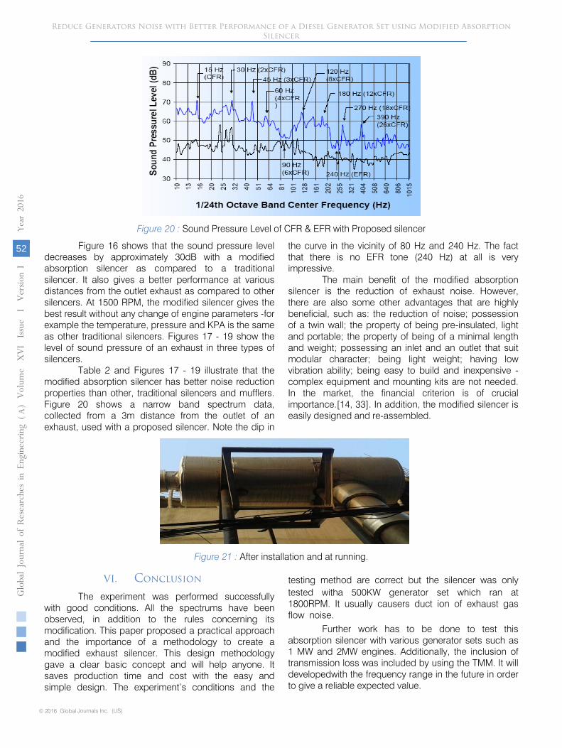
Figure 20 : Sound Pressure Level of CFR & EFR with Proposed silencer
Figure 16 shows that the sound pressure level decreases by approximately 30dB with a modified absorption silencer as compared to a traditional silencer. It also gives a better performance at various distances from the outlet exhaust as compared to other silencers. At 1500 RPM, the modified silencer gives the best result without any change of engine parameters -for example the temperature, pressure and KPA is the same as other traditional silencers. Figures 17 - 19 show the level of sound pressure of an exhaust in three types of silencers.
Table 2 and Figures 17 - 19 illustrate that the modified absorption silencer has better noise reduction properties than other, traditional silencers and mufflers. Figure 20 shows a narrow band spectrum data, collected from a 3m distance from the outlet of an exhaust, used with a proposed silencer. Note the dip in
the curve in the vicinity of 80 Hz and 240 Hz. The fact that there is no EFR tone (240 Hz) at all is very impressive.
The main benefit of the modified absorption silencer is the reduction of exhaust noise. However, there are also some other advantages that are highly beneficial, such as: the reduction of noise; possession of a twin wall; the property of being pre-insulated, light and portable; the property of being of a minimal length and weight; possessing an inlet and an outlet that suit modular character; being light weight; having low vibration ability; being easy to build and inexpensive - complex equipment and mounting kits are not needed. In the market, the financial criterion is of crucial importance.[14, 33]. In addition, the modified silencer is easily designed and re-assembled.
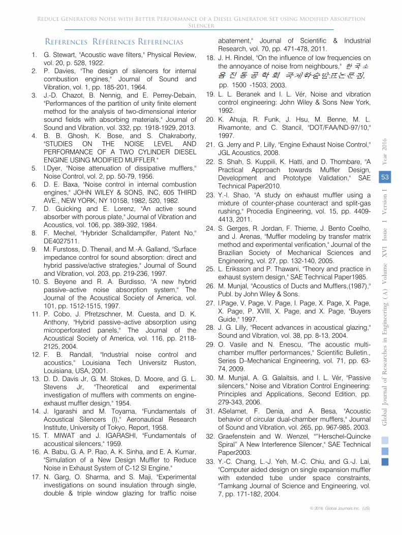
Figure 21 : After installation and at running.
VI.
Conclusion
The experiment was performed successfully with good conditions. All the spectrums have been observed, in addition to the rules concerning its modification. This paper proposed a practical approach and the importance of a methodology to create a modified exhaust silencer. This design methodology gave a clear basic concept and will help anyone. It saves production time and cost with the easy and simple design. The experiment’s conditions and the
testing method are correct but the silencer was only tested witha 500KW generator set which ran at 1800RPM. It usually causers
duct ion
of exhaust gas flow noise.
Further work has to be done to test this absorption silencer with various generator sets such as 1 MW and 2MW engines. Additionally, the inclusion of transmission loss was included by using the TMM. It will developedwith the frequency range in the future in order to give a reliable expected value.
Reduce Generators Noise with Better Performance of a Diesel Generator Set using Modified Absorption Silencer
© 2016 Global Journals Inc. (US)
Globa
l Jo
urna
l of
Resea
rche
s in E
nginee
ring
(
)Volum
e X
VI Issue
I V
ersion
I
52
Year
2016
A
References Références Referencias
1. G. Stewart, "Acoustic wave filters," Physical Review, vol. 20, p. 528, 1922.
2. P. Davies, "The design of silencers for internal combustion engines," Journal of Sound and Vibration, vol. 1, pp. 185-201, 1964.
3. J.-D. Chazot, B. Nennig, and E. Perrey-Debain, "Performances of the partition of unity finite element method for the analysis of two-dimensional interior sound fields with absorbing materials," Journal of Sound and Vibration, vol. 332, pp. 1918-1929, 2013.
4. B. B. Ghosh, K. Bose, and S. Chakraborty, "STUDIES ON THE NOISE LEVEL AND PERFORMANCE OF A TWO CYLINDER DIESEL ENGINE USING MODIFIED MUFFLER."
5. l.Dyer, "Noise attenuation of dissipative mufflers," Noise Control, vol. 2, pp. 50-79, 1956.
6. D. E. Baxa, "Noise control in internal combustion engines," JOHN WILEY & SONS, INC, 605 THIRD AVE., NEW YORK, NY 10158, 1982, 520, 1982.
7. D. Guicking and E. Lorenz, "An active sound absorber with porous plate," Journal of Vibration and Acoustics, vol. 106, pp. 389-392, 1984.
8. F. Mechel, "Hybrider Schalldamplfer, Patent No," DE4027511.
9. M. Furstoss, D. Thenail, and M.-A. Galland, "Surface impedance control for sound absorption: direct and hybrid passive/active strategies," Journal of Sound and Vibration, vol. 203, pp. 219-236, 1997.
10. S. Beyene and R. A. Burdisso, "A new hybrid passive–active noise absorption system," The Journal of the Acoustical Society of America, vol. 101, pp. 1512-1515, 1997.
11. P. Cobo, J. Pfretzschner, M. Cuesta, and D. K. Anthony, "Hybrid passive–active absorption using microperforated panels," The Journal of the Acoustical Society of America, vol. 116, pp. 2118-2125, 2004.
12. F. B. Randall, "Industrial noise control and acoustics," Louisiana Tech Universitz Ruston, Louisiana, USA, 2001.
13. D. D. Davis Jr, G. M. Stokes, D. Moore, and G. L. Stevens Jr, "Theoretical and experimental investigation of mufflers with comments on engine-exhaust muffler design," 1954.
14. J. Igarashi and M. Toyama, "Fundamentals of Acoustical Silencers (I)," Aeronautical Research Institute, University of Tokyo, Report, 1958.
15. T. MIWAT and J. IGARASHI, "Fundamentals of acoustical silencers," 1959.
16. A. Babu, G. A. P. Rao, A. K. Sinha, and E. A. Kumar, "Simulation of a New Design Muffler to Reduce Noise in Exhaust System of C-12 SI Engine."
17. N. Garg, O. Sharma, and S. Maji, "Experimental investigations on sound insulation through single, double & triple window glazing for traffic noise
abatement," Journal of Scientific & Industrial Research, vol. 70, pp. 471-478, 2011.
18. J. H. Rindel, "On the influence of low frequencies on the annoyance of noise from neighbours,"
pp. 1500 -1503, 2003.
19. L. L. Beranek and I. L. Vér, Noise and vibration control engineering: John Wiley & Sons New York, 1992.
20. K. Ahuja, R. Funk, J. Hsu, M. Benne, M. L. Rivamonte, and C. Stancil, "DOT/FAA/ND-97/10," 1997.
21. G. Jerry and P. Lilly, "Engine Exhaust Noise Control," JGL Acoustics, 2008.
22. S. Shah, S. Kuppili, K. Hatti, and D. Thombare, "A Practical Approach towards Muffler Design, Development and Prototype Validation," SAE Technical Paper2010.
23. Y.-l. Shao, "A study on exhaust muffler using a mixture of counter-phase counteract and split-gas rushing," Procedia Engineering, vol. 15, pp. 4409-4413, 2011.
24. S. Gerges, R. Jordan, F. Thieme, J.
Bento Coelho,
and J. Arenas, "Muffler modeling by transfer matrix method and experimental verification," Journal of the Brazilian Society of Mechanical Sciences and Engineering, vol. 27, pp. 132-140, 2005.
25. L. Eriksson and P. Thawani, "Theory and practice in exhaust system design," SAE Technical Paper1985.
26. M. Munjal, "Acoustics of Ducts and Mufflers,(1987)," Publ. by John Wiley & Sons.
27. l.Page, V. Page, V. Page, I. Page, X. Page, X. Page, X. Page, P. XVIII, X. Page, and X. Page, "Buyers Guide," 1997.
28. J. G. Lilly, "Recent advances in acoustical glazing," Sound and Vibration, vol. 38, pp. 8-13, 2004.
29.
O. Vasile and N. Enescu, "The acoustic multi-chamber muffler performances," Scientific Bulletin., Series D–Mechanical Engineering, vol. 71, pp. 63-74, 2009.
30.
M. Munjal, A. G. Galaitsis, and I. L. Vér, "Passive silencers," Noise and Vibration Control Engineering: Principles and Applications, Second Edition, pp. 279-343, 2006.
31.
ASelamet, F. Denia, and A. Besa, "Acoustic behavior of circular dual-chamber mufflers," Journal of Sound and Vibration, vol. 265, pp. 967-985, 2003.
32.
Graefenstein and W. Wenzel, "“Herschel-Quincke Spiral” A New Interference Silencer," SAE Technical Paper2003.
33.
Y.-C. Chang, L.-J. Yeh, M.-C. Chiu, and G.-J. Lai, "Computer aided design on single expansion muffler with extended
tube under space constraints, "Tamkang Journal of Science and Engineering, vol. 7, pp. 171-182, 2004.
Reduce Generators Noise with Better Performance of a Diesel Generator Set using Modified Absorption Silencer
Gl oba
l Jo
urna
l of
Resea
rche
s in E
nginee
ring
(
)Volum
e X
VI Issue
I V
ersion
I
53
Year
2016
A
© 2016 Global Journals Inc. (US)

This page is intentionally left blank
© 2016 Global Journals Inc. (US)
Globa
l Jo
urna
l of
Resea
rche
s in E
nginee
ring
(
)Volum
e X
VI Issue
I V
ersion
I
54
Year
2016
AReduce Generators Noise with Better Performance of a Diesel Generator Set using Modified Absorption
Silencer