Embed Size (px)
Citation preview

IEEE TRANSACTIONS ON CIRCUITS AND SYSTEMS—I: REGULAR PAPERS, VOL. 63, NO. 3, MARCH 2016 379
Reducing Phase Noise in Multi-Phase OscillatorsPaolo Maffezzoni, Senior Member, IEEE, Bichoy Bahr, Student Member, IEEE,
Zheng Zhang, Member, IEEE, and Luca Daniel, Member, IEEE
Abstract—This paper investigates phase noise mechanism inarrays of resonant LC oscillators. Such arrays represent todaya promising solution for the generation of multi-phase signalsneeded in several advanced applications. The analysis presentedin this paper relies on consolidated phase-domain macromodelsas well as on the original concept of noise transfer function il-lustrated herein. The proposed analysis sheds new light on noisegeneration in oscillator arrays and is able to explain certain noisedegradation effects observed in nonreciprocal coupling networks.Phase-domain simulation together with noise transfer functionconcept provide a very efficient computational tool for rapid calcu-lations of phase response and output noise. Thanks to this efficienttool and to the gained qualitative understanding, we are able topropose a chain array configuration enhanced by the injection ofa clean, low-noise signal. In this paper, it is shown how the injectedchain array can provide the prescribed phase separation whilesignificantly reducing output phase noise.
Index Terms—Multi-phase oscillators, noise reduction, noisetransfer function.
I. INTRODUCTION
ARRAYS of weakly coupled resonant oscillators can beemployed to generate multi-phase harmonic signals, i.e.,
sinusoids with the same oscillating frequency and with pre-scribed phase separations. Multi-phase signals are now indis-pensable in many advanced emerging applications, such as inextremely-high frequency synthesis and multiphase clock dis-tribution [1]–[3], as well as in brain-inspired parallel computingfor data analysis [4]. For such applications, stringent phase-noise specifications are required.
Previous studies and experimental evidences have shownhow coupled oscillators can exhibit a reduction of their phasenoise compared to the free-running case [5], [6]. More specif-ically, the phase noise spectrum near the carrier is reducedby a factor proportional to the number N of stages in thearray, while the noise spectrum far from the carrier remainsalmost unchanged. Such a noise reduction effect is commonlynot enough to meet noise specifications. In fact, the noisespectrum near the carrier continues to be shaped as 1/f2 (or
Manuscript received November 9, 2015; revised December 23, 2015;accepted January 28, 2016. Date of publication February 26, 2016; date ofcurrent version April 5, 2016. This paper was recommended by AssociateEditor P.-I. Mak.
P. Maffezzoni is with Politecnico di Milano, 20133 Milan, Italy (e-mail:[email protected]).
B. Bahr, Z. Zhang, and L. Daniel are with Massachusetts Institute ofTechnology (MIT), Cambridge, MA 02139 USA (e-mail: [email protected];[email protected]; [email protected]).
Color versions of one or more of the figures in this paper are available onlineat http://ieeexplore.ieee.org.
Digital Object Identifier 10.1109/TCSI.2016.2525078
1/f3 down to the corner frequency where flicker noise getsdominant) even if reduced compared to the free-running case.In addition, it has been shown that certain array configurations,such as nonreciprocal unilaterally coupled chain arrays, mayresult in unexpected deterioration of the noise spectrum with theappearance of spurious peaks [5], [6]. This anomalous behaviorand performance limitations call for further investigations.
In this paper, we use the phase-domain macromodel pre-sented in [6] and the concept of noise transfer function (NTF) toshed new light on phase-noise mechanism in oscillator arrays.Thanks to this understanding, we demonstrate that the noiseperformance of the multi-phase chain array can be definitelyenhanced, even at low frequencies, by properly injecting anexternal clean low-noise signal. Such a clean signal is in factavailable in the majority of frequency synthesizers and clockgeneration systems and is obtained by locking one oscillator(within a PLL or with a pulsed injection) to a stable low-frequency reference (i.e., the output of a crystal oscillator). Theproblem with an external injection is that it may disrupt thecorrect phase separation if not properly dimensioned. In thispaper, we show how injection strength can be set so as to reducenoise while preserving the prescribed phase separation.
The novel contributions of this paper may be summarized asfollows:
1) We investigate the form of the NTFs that describe howthe noise sources internal to oscillators are transferred tothe output phase noise. We derive how such NTFs dependon the specific choices of array topologies.
2) A behavioral method is provided that allows modelinginternal noise sources in locked oscillators through asingle macro noise source.
3) A chain array topology enhanced by the injection of aclean, low-noise signal is presented. It is shown that theproposed array provides multi-phase signals with π/Nphase separation while improving noise spectrum over awide frequency band. Results are checked, in a few testcases, via comparisons with SpectreRF simulations.
The topics listed above are organized in the paper as follows:Section II describes oscillator array structure and review itsphase-domain model. In Section III, we illustrate phase noisemodeling for individual free-running or locked oscillators andthen we describe array phase noise analysis and NTF concept.In Section IV, we focus on the relevant case of a chain arrayand derive the conditions under which an external injectionbecomes effective in noise reduction. Finally, Section V isdevoted to numerical experiments and validation.
1549-8328 © 2016 IEEE. Personal use is permitted, but republication/redistribution requires IEEE permission.See http://www.ieee.org/publications_standards/publications/rights/index.html for more information.
380 IEEE TRANSACTIONS ON CIRCUITS AND SYSTEMS—I: REGULAR PAPERS, VOL. 63, NO. 3, MARCH 2016
Fig. 1. (Top) Circuit of two of the oscillators forming the array and couplingtransistors. (Bottom) Schematic representation.
II. OSCILLATOR ARRAY
We consider an array composed with N identical LC reso-nant CMOS oscillators, as shown in Fig. 1 (top). Each oscilla-tor, when free-running, oscillates autonomously at the angularfrequency ω0 and its output voltage, measured at the LC tanknodes, is purely harmonic
V0(t) = VM cos(ω0t) (1)
with VM being the voltage amplitude. To construct the array,oscillators are coupled by a transconductance, implemented bydifferential-pair transistors. Fig. 1 (top) shows the couplingcircuit between two oscillator stages of the array with indexk and j. In this example, a differential-pair circuit reads thevoltage Vk(t) at the kth-stage output and injects a proportionaldifferential current
Ij(t) = gjk Vk(t) (2)
into the tank nodes of the jth oscillator. The module of param-eter gjk corresponds to the transconductance of the associateddifferential-pair transistor while its sign refers to the way dif-ferential current Ij(t) is injected into the nodes n+
j and n−j .
In this paper, it is conventionally assumed that a positive gjkcorresponds to Ij(t) exiting node n+
j and entering n−j , as it
is the case shown in Fig. 1 (top). A negative gjk, instead,corresponds to Ij(t) exiting node n−
j and entering n+j and can
be implemented by switching the way differential-pair drainsare connected to the injected nodes. In the array in Fig. 1 (top)coupling is bilateral since a second differential-pair transistorreads the voltage Vj(t) of the jth stage and injects a propor-tional current Ik(t) = gkjVj(t) into the kth stage. The arraytopology can be schematically represented by the system shownin Fig. 1 (bottom) where couplings are indicated by orientedarches of strength gjk. Array topology can be described bythe conductance matrix G = {gjk} ∈ R
N×N that collects allcoupling strength coefficients gjk .
It is known that for resonant oscillators with well matchedfree-running frequency, weak coupling (e.g., with the transcon-ductance of coupling transistors one order of magnitude smaller
than that of oscillator transistors) is enough to keep oscillatorssynchronized. Under this hypothesis, the array response canbe realistically simulated with a phase-domain macromodel[7]–[12]. According to this method, the output voltage of thekth oscillator in the array is written as
Vk(t) = V0 (t+ αk(t)) = VM cos (ω0t+ ω0αk(t)) (3)
where αk(t) represents the time-dependent time shift of theperturbed response with respect to the free-running one andφk(t) = ω0αk(t) is the associated excess phase variable. Then,the time-shift variable and injected current Ik(t) are related bythe scalar differential equation [7], [8]
α̇k(t) = Γk (t+ αk(t)) Ik(t) (4)
where Γk(t) is the periodic phase-sensitivity function to currentinjection at the tank. It has been found that for LC resonantoscillators Γ(t) is sinusoidal and delayed by a π/2 phase anglewith respect to the output response [16], i.e.,
Γk(t) = ΓM cos(ω0t− π/2). (5)
The phase response of the whole chain array is governed by thefollowing set of nonlinear differential-algebraic equations:
α̇k(t) =Γk (t+ αk(t)) Ik(t) (6a)
Ik(t) =
N∑j=1
gkj Vj (t+ αj(t)) . (6b)
Array synchronization is achieved if, asymptotically for t→∞,the time-shift variables αk(t) approach the waveforms α̃k(t)such that the associated phases φk(t) = ω0α̃k(t) satisfy
limt→∞
φk(t)− φj(t) = Φkj (7)
for all k and j, where Φkj is a constant [13]. In other terms,the phase difference (or phase separation) between any twooscillators converges to a constant value and the oscillator arraygenerates a multi-phase harmonic signal. Numerical integrationof (6) allows us to efficiently verify whether synchronizationcondition (7) is satisfied and to calculate the steady-state phaseseparations Φkj in case of synchronization.
III. PHASE-NOISE ANALYSIS
Phase-domain model (3) is suitable to analyze phase-noiseeffects in oscillator arrays. Noise sources internal to eachoscillator produce random fluctuations of the time shift variableαk(t) and of the associated phase φk(t) (referred to as phasenoise). When many oscillators are coupled to form an array,the internal noise sources of oscillators interact among themthrough a complex mechanism that results in the final outputphase noise. Such a mechanism can be investigated via a twostep procedure that consists in modeling noise in the individualuncoupled oscillator through a macro noise source, and thenusing the phase macromodel (6), augmented with such macronoise sources, to evaluate array phase noise.
MAFFEZZONI et al.: REDUCING PHASE NOISE IN MULTI-PHASE OSCILLATORS 381
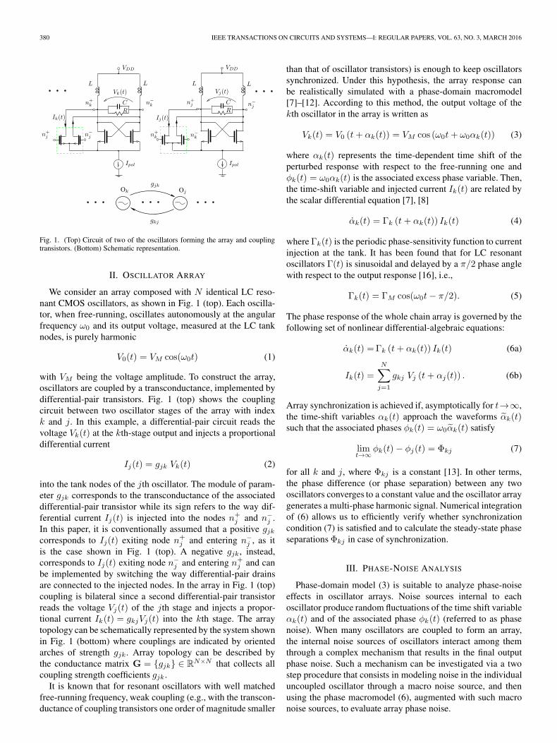
Fig. 2. (Solid line) Output noise spectrum Sfreeφ (f) for a free-running oscilla-
tor; (dashed line) spectrum Sfreen (f) of the associated macro noise source.
A. Individual Free-Running Oscillator
For a free-running oscillator, phase noise can be described,in a compact way, by the average stochastic equation
α̇(t) = n(t) (8)
where n(t) is a macro noise source, with power spectral density(PSD) Sn(f), that accounts for all of the device noise sourcesinternal to the oscillator circuit [17], [18]. The PSD of thephase-noise variable φ(t) = ω0α(t) is given by
Sφ(f) =f20
f2· Sn(f) = NTF(f) ω2
0 Sn(f) (9)
where NTF(f) = 1/|i2πf |2 is the noise transfer function (nor-malized to ω0) that describes how the power noise of the sourcen(t) is transferred to the output, whereas in this paper we denotei =
√−1 the imaginary unit.
For a given oscillator (i.e., with given circuit parameters)working in free-running mode the output phase-noise spectrumSfreeφ (f) is a known data. In fact, it can be determined either
via detailed circuit-level simulations or through laboratory mea-surements. Such a spectrum is formed of two contributions
Sfreeφ (f) =
Kw
f2+
Kf
f3(10)
due to white and flicker noise sources, respectively, as it isqualitatively portrayed in Fig. 2. In this figure, vertical andhorizontal axis are scaled logarithmically and f representsoffset frequency. The values of the parameters Kw and Kf in(10) can be extracted by fitting the shape of the available outputspectrum. In view of (9), the PSD of the associated macro noisesource nfree(t) is deduced to be
Sfreen (f) =
Kw
f20
+Kf
f20
1
f(11)
as reported in Fig. 2, where fC represents the corner frequencydown which flicker noise becomes relevant.
B. Oscillator Locked to a Reference
A clean, low-noise and high-frequency oscillator can beobtained by locking one oscillator to a stable low-frequency
Fig. 3. (Solid line) Output noise spectrum Slockφ (f) of a locked oscillator;
(dashed line) spectrum Slockn (f) of the associated macro noise source.
reference (i.e., a crystal oscillator) within a control system,such as a phase-locked loop (PLL) or a pulsed-injection-lockedoscillator (PILO) [14]. The control system performs a low-passfiltering of the oscillator phase noise. Hence, denoting fB thefilter pole frequency (i.e., the control bandwidth), the outputspectrum of the locked oscillator results of the type
Slockφ (f) =
(Kw +
Kf
f
)1
|if + fB|2(12)
as it is qualitatively shown in Fig. 3 under the realistic hypothe-sis that fB � fC . In view of (9), we derive that the macro noisesource nlock(t) to be associated to a clean low-noise oscillatorhas the PSD
Slockn (f) =
(Kw +
Kf
f
)1
f20
f2
|if + fB|2(13)
which vanishes for f � fB , as shown in Fig. 3.
C. Oscillator Array
The oscillator array is formed by coupling N free-runningLC oscillators as shown in Fig. 1. In addition, one low-noise os-cillator (whose noise model has been described in Section III-B)may be present in the system. An example of such an arraytopology is investigated in the next section and is shown inFig. 6. The low-noise oscillator is supposed to inject unilaterallyinto the other stages of the array so that its behavior (and its lownoise output) is not affected by array operation.
To study phase noise in the oscillator array, the macronoise source nk(t) associated to the kth oscillator is added to(6a), i.e.,
α̇k(t) = Γk (t+ αk(t)) Ik(t) + nk(t). (14)
For oscillators that were running in free mode before beingcoupled, the noise source nk(t) in (14) has PSD of the type(11), whereas for the low-noise oscillator, the associated noisesource nk(t) has PSD of the type (13).

382 IEEE TRANSACTIONS ON CIRCUITS AND SYSTEMS—I: REGULAR PAPERS, VOL. 63, NO. 3, MARCH 2016
Combining (14) with (6b), we are led to the following set ofstochastic differential equations:
α̇k(t)=Γk (t+αk(t))·N∑j=1
gkj Vj(t+αj(t))+nk(t). (15)
The presence of noise sources induces extra random fluctu-ations τk(t) of variables αk(t) around their noiseless regimevalues α̃k(t), i.e.
αk(t) = α̃k(t) + τk(t). (16)
Exploiting the fact that τk(t) � α̃k(t), in the Appendix it isshown that the PSD of the noise-induced excess phase θk(t) =ω0τk(t) for the kth oscillator in the array is given by
Sθk(f) =
N∑j=1
NTFkj(f) ω20 Snj
(f) (17)
where
NTFkj(f) = |tkj(f)|2 . (18)
In the expression above, the complex coefficient tkj(f) repre-sents the signal transfer function from input nj(t) of jth oscil-lator to output phase θk(t) of kth oscillator, while NTFkj(f) isthe associated noise transfer function in terms of noise power.
Furthermore, transfer functions tkj(f) are the entries of thecomplex matrix
T(f) = {tkj} = (i2πfIN −A)−1 (19)
where IN is the identity matrix of size N , “ −1” denotes inverseoperator, while A = {akj} ∈ R
N×N is defined as follows:
akk =BN∑
j=1,j �=k
gkj cos(Φkj)
akj = −B gkj cos(Φkj) for k �= j (20)
with B = ω0ΓMVM/2, as derived in the Appendix.In the remainder of this section, we better investigate the
form of the signal transfer functions tkj(f). As underlined inthe Appendix, for any phase separation Φkj that correspondsto a stable solution of (6), the eigenvalues λk of A are suchthat: λ1 = 0, while remaining ones have negative real part(λk) < 0 for k = 2, . . . , N . For exposition simplicity, in whatfollows we suppose that such eigenvalues are all distinct (thisis in fact the case for the chain array topologies that we willconsider later). Under this hypothesis, matrix A has eigenvaluedecomposition as follows:
A = V ·Dλ ·WT (21)
where the diagonal matrix Dλ collects the λk eigenvalues,whereas the columns of matrix V are the related eigenvectorsVk . In particular, eigenvector V1 associated to λ1 = 0 spans thenull space of matrix A, i.e., A · V1 = 0. The columns Wj ofmatrix W defined as WT = V−1 are the rows of the inversematrix V−1. From (19), it results
T(f) = V ·Din ·WT (22)
where the diagonal matrix Din collects the elements (i2πf −λk)
−1. Expression (22) can be further expanded into
T(f) = V1WT
1
1
i2πf+
N∑k=2
VkWT
k
1
i2πf − λk. (23)
The following qualitative observations are in order.
1) Coupling oscillators to form an array results in filteringthe macro noise source nk(t) through transfer functionstkj(f) whose poles are the eigenvalues λk of matrix A.
2) If eigenvalues λk are complex conjugate (i.e., they havea nonzero imaginary part), these transfer functions maygive resonance effects with unwanted spikes in the out-put phase noise spectrum. This phenomenon, which wasobserved in previous studies [5] and [6], becomes morepronounced when the number N of stages is increased.Such spikes in the output spectrum are removed if theconductance matrix G = gjk is made symmetric, i.e., ifcoupling is bilateral with gkj = gjk. In this case in fact Ais symmetric and thus its eigenvalues λk are purely real,which eliminates any resonance effect. For these reasons,from now on our analysis will be focused on symmetricarrays.
3) The first term in expansion (23) is the most critical onesince its transfer function ∝ 1/f , which corresponds tointegrating noise in time, produces large phase noisecomponents at low frequencies.
4) Nonzero elements of vector W1 tell us which noisesources in the array are actually integrated through 1/ftransfer function, in other words the noise source np(t)associated to pth oscillator is integrated in time if andonly if the pth element in vector W1 is nonzero. Asa result, in order to minimize output noise, vector W1
should have nonzero elements only in correspondence tolow-noise oscillators.
We conclude this section by observing that vector W1 is theeigenvector of AT associated to λ1 = 0 and thus it spans thenull space of matrix AT . This is easily seen by transposing (21)and observing that WT = V−1, which yields
AT = W ·Dλ ·W−1. (24)
IV. CHAIN ARRAYS WITH CLEAN SIGNAL INJECTION
An array topology of particular importance is the chain arraywhere only nearest neighbor oscillators are coupled, i.e., gkj �=0only for j ∈ (k − 1, k + 1). Chain arrays are interesting forimplementation reasons since they require a limited numberof coupling stages. More importantly, it has been proved thatfor a synchronized chain array only one steady-state phaseseparationΦkj corresponds to a stable solution of (6) and thus itis observable in practice [6], [15]. This stable phase separationonly depends on array topology and coupling strengths, i.e., onconductance matrix G, while it does not depend on initial phaseconditions.
In this paper, in particular, we will focus on the chain arraytopology portrayed in Fig. 4 where neighboring oscillators are

MAFFEZZONI et al.: REDUCING PHASE NOISE IN MULTI-PHASE OSCILLATORS 383
Fig. 4. Chain array topology.
Fig. 5. (Top) Conductance matrix G for the array in Fig. 4. (Bottom) MatrixAT and its null space �W1.
connected by a symmetric bilateral coupling of strength −g(with g being the differential-pair transistor transconductance).The chain array is closed at the ends with the first and last stagesthat are bilaterally coupled with strength g. The associatedconductance matrix G is reported in Fig. 5 (top).
For this chain array, it has been proved that when synchro-nization is achieved, steady-state phase variables are such that
Φk+1,k = φk+1(t)− φk(t) = ±π/N. (25)
Thus, denoting x = gB cos(Φk+1,k), the symmetric matrixA = AT exhibits the structure shown in Fig. 5 (bottom) andits null space is spanned by the vector W1 formed by all ones.This implies that all of the noise sources nk(t) in the array aretransferred to the outputs through the critical network function1/i2πf . We thus expect that for the chain array in Fig. 4 theoutput power spectra, even if reduced compared to the free-running case, will continue to be shaped as 1/f2 (and 1/f3
at the very low frequencies down to fC).To improve the noise performance, in what follows we inves-
tigate the enhanced array arrangement shown in Fig. 6: in thisarrangement the oscillators in the chain array are injected uni-laterally with the clean signal provided by a low-noise oscillatorlabelled O1. The macro noise source n1(t) associated to O1 hasthe PSD described in (11) which vanishes for f < fB . Signalinjection from O1 should reduce the small-signal phase fluc-tuations induced by noise while minimally affecting the large-signal phases φk(t) and related phase separations. To achievethis goal, the injection strength is fixed to a value gr � g. The
Fig. 6. Chain array injected by the low-noise oscillator O1.
Fig. 7. (Top) Conductance matrix G for the array with injection in Fig. 6.(Bottom) Matrix AT and its null space �W1.
conductance matrix G for the injected chain is augmented byan all-zero row (oscillator 1 is not injected by others) and onecolumn collecting injection strength coefficients gr as shown inFig. 7 (top). Supposing that (25) remains unchanged, and adopt-ing the notations x = gB cos(Φk+1,k), xr = grB cos(Φk+1,k),and y = −2x+ xr, the structure of the AT matrix (i.e., itsnonzero entries) is shown in Fig. 7 (bottom). The null-spacespanning vector W1 has a one in the first position and all zerosin the others. This means that in the injected array the onlynoise source which is transferred through the critical networkfunction 1/i2πf is that of the clean source n1(t) associated tothe locked oscillator. This is expected to improve significantlythe array noise performance at the low frequencies.
V. NUMERICAL RESULTS
In this section, we present numerical results for chain arraysformed with N = 5 identical LC oscillators and for configura-tions without external injection and with injection. The circuitof each LC oscillator is shown in Fig. 1 with the device param-eters reported in Table I. A single oscillator is first simulatedwith the periodic steady state (pss) analysis of SpectreRF and
384 IEEE TRANSACTIONS ON CIRCUITS AND SYSTEMS—I: REGULAR PAPERS, VOL. 63, NO. 3, MARCH 2016
TABLE IPARAMETERS OF THE LC OSCILLATOR
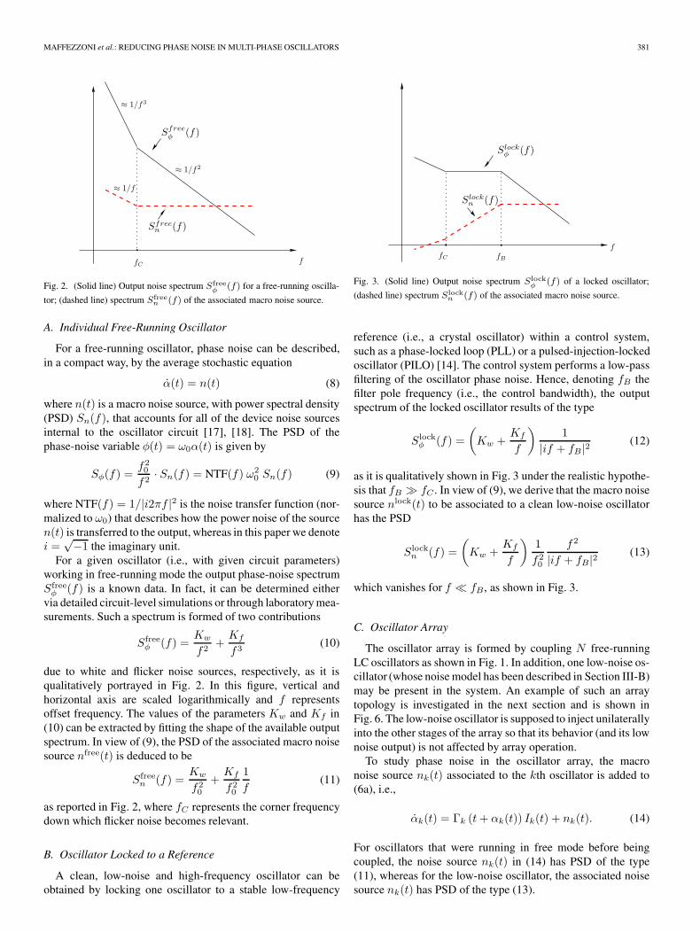
Fig. 8. Phase response of the array with no injection.
then the Γ(t) function is extracted with the method described in[16]. The circuit oscillates at f0 = 1.0261 GHz and its outputvoltage V0(t) and Γ(t) function are harmonic as in (1) and (5)with peak values VM = 3.45V, ΓM = 151.8A−1, respectively.
Oscillator stages are coupled as in Fig. 4, to form a chainarray with no injection. A fixed differential-pair transconduc-tance parameter g = g0 = 10−5 Ω−1 is chosen. The phaseresponse of the chain array is then simulated with the model(6), starting from initial random phase values. Fig. 8 showsthe time evolution of the φk(t) phase variables: the phasedifference among nearby oscillators converges to the constantvalue Δφ = π/5 ≈ 0.628 rad meaning that the oscillator arrayis synchronized.
Hence, the array with unilateral external injection as de-scribed in Fig. 6 is considered: the low-noise oscillator O1
injects unilaterally in the chain stages, numbered from 2 to N +1 = 6, with transconductance strength gr = g0r = 10−6 Ω−1.Fig. 9 shows the simulated time evolution of the φk(t) phasevariables for the array with injection: compared to the casewith no injection, array synchronization takes a longer time buteventually phase separations among chain array stages, i.e., fork = 2, . . . , N + 1, converge to Δφ ≈ π/5 with a relative errorwhich is smaller than 2%. Besides that, chain array oscillatorssynchronize with the external signal in the way that oscillatorO4, in the center of the chain array, is almost in antiphasewith O1, i.e., φ1(t)− φ4(t) ≈ π. This behavior is fully con-firmed by detailed circuit-level simulations with SpectreRF.Fig. 10 reports the oscillators output voltages derived with thephase-domain simulation and model (3) and those obtainedthrough simulation with SpectreRF: the waveforms (after beingproperly delayed) match with great accuracy. We thus conclude
Fig. 9. Phase response of the array with external injection.
Fig. 10. Output voltages for the array with injection: (Solid line) waveformsobtained with the phase-domain model; (square marker) waveforms simulatedwith SpectreRF.
that, for the selected coupling strengths, the prescribed phaseseparation is preserved in the presence of external injection.
We pass now to analyze noise. To this aim, the output phasenoise of the individual free-running oscillator is computedwith the pnoise analysis of SpectreRF [19]. For the consideredoscillator device, phase noise is dominated by the thermal whitenoise down to a corner frequency fC of some hundreds hertz.Over the frequency range of interest, the spectrum of the free-running oscillator is well approximated by
Sφ(f) ≈100
f2rad2/Hz. (26)
which corresponds to (10) with Kf = 0. In view of (9) or (11),the associated macro noise source n(t) has a constant PSDSn(f) = S̃n = 10−16 rad2/Hz. Noise in each oscillator in thechain array is thus modelled with a macro noise source nj(t)
having constant PSD Snj(f) = S̃n.

MAFFEZZONI et al.: REDUCING PHASE NOISE IN MULTI-PHASE OSCILLATORS 385
Fig. 11. (i) NTF(f) for the free-running oscillator; (ii) NTF22(f) in the arraywith no injection; (iii) NTF2j(f) with j ∈ (1, 3, 4, 5) in the array with noinjection.
For the array configuration with external injection, oscillatorO1 is a locked low-noise oscillator whose PSD of the type (12)is well approximated by
Sφ1(f) =
100
|if + fB|2(27)
with control bandwidth fB = 10 MHz. From (11), we deducethat macro noise source n1(t) has PSD
Sn1(f) =
100
f20
f2
|if + fB|2. (28)
First, we focus on the array with no injection and, startingfrom the simulated phase separations Φkj shown in Fig. 8 andusing (19) and (20), we calculate the NTFs. Fig. 11 showsNTF22(f) describing self-noise transfer from source n2(t) tooutput θ2(t) for oscillator number 2 (the same curves arefound for the other oscillators in the chain). It also showsNTF2j(f), with j ∈ (1, 3, 4, 5), describing noise transfer fromother oscillators. We conclude that, even though such NTFsare attenuated compared to NTF(f) = 1/|i2πf |2 for the free-running oscillator, they still vary as 1/f2 at the low frequencies.
Second, we calculate the NTFs for the array with injectionusing the simulated phase separations Φkj shown in Fig. 9.In this case, we see from Fig. 12 how self-noise functionNTF22(f) and transfer functions NTF2j(f) for j ∈ (3, 4, 5, 6)are significantly reduced down to ≈1 MHz where they tendto constant values. The only NTF that keeps varying as 1/f2
is the NTF21(f) that weights clean noise source n1(t). Thisshould reduce the total output phase noise. Fig. 13 shows thetotal output phase noise Sθ2(f) computed with the phase-domain model for the cases of array without injection andwith injection. External injection is seen to yield a remark-able noise reduction at the low frequencies. This result isfully confirmed by circuit-level phase noise simulations withSpectreRF as reported in Fig. 13 for comparison. DetailedSpectreRF simulation is indeed time consuming, (e.g., for therelatively simple case of N = 5 with external injection, the
Fig. 12. (i) NTF(f) for the free-running oscillator; (ii) NTF22(f) in the arraywith injection; (iii) NTF2j(f) with j ∈ (3, 4, 5, 6) in the array with injection;(iv) NTF21(f).
Fig. 13. (i) Phase-noise Sφ(f) in the free-running oscillator. (ii) Output phase-noise Sθ2 (f) in the array without injection. (iii) Output phase-noise Sθ2(f) inthe array with injection. Solid lines refer to phase-domain simulations, squaremarkers refer to simulations with SpectreRF.
single simulation requires about 20 minutes on a quad core) andthus it is used only for verification purpose. By contrast, phasedomain analysis requires only a few seconds and thus it allowsextensive exploration of array performances as a function ofparameters values. In the remainder of this section, we exploitthe efficiency of the phase domain model to investigate twoissues that are relevant for practical implementations. A firstissue is connected to the variability of coupling coefficientsdue to fabrication uncertainty. To study this effect, we assumethat coupling transconductance g and injection strength grundergo random variations around their nominal values g0
and g0r , according to g = g0 · [1 + U(−a, a)] and gr = g0r ·[1 + U(−a, a)], respectively. The symbol U(−a, a) denotesa stochastic variable uniformly distributed over the interval(−a, a). Hence, we perform Monte Carlo simulations wherefor each randomly generated g and gr values, we simulatedthe phase-domain response of the injected array and determine

386 IEEE TRANSACTIONS ON CIRCUITS AND SYSTEMS—I: REGULAR PAPERS, VOL. 63, NO. 3, MARCH 2016
Fig. 14. Statistical distribution of the phase difference Φ23 = φ2(t) − φ3(t)due to coupling coefficients variability.
the steady-state phase-difference values. Fig. 14 shows the sta-tistical distribution of the asymptotic phase difference φ2(t)−φ3(t) = Φ23 (very similar curves are obtained for the otherdifferences) calculated with 500 Monte Carlo iterations and for±2% coupling variability, i.e., a = 0.02: the resulting phasedifference tends to be normally distributed around its meanvalue 0.625 rad with standard deviation <1%. Thus, the as-sumed variability of coupling coefficients does not significantlyaffect the array phase response. We also verify that the asso-ciated phase-noise spectra remain very close to the curve (iii)in Fig. 13 calculated in the absence of variability. It is worthunderlining that the whole Monte Carlo simulation with thephase-domain model is accomplished in only 25 minutes whileit would require more than one week if it were performed withdetailed SpectreRF simulations.
The second issue is related to the importance of tightlymatching the frequency ω1 of the locked low-noise oscillatorO1 to the free-running frequency ω0 = 2πf0 of the oscillatorsin the array. To investigate this aspect, we assume ω1 �= ωk =ω0 for k = 2, . . . , N + 1, and we study the effect of a smallfrequency detuning ω0 − ω1 = Δω = 2π × (1 MHz). In thepresence of frequency detuning, synchronization of each os-cillator in the array with the low-noise one requires that, fort → ∞, the following condition holds [13]:
ω1t+ ω1α1(t)− ωkt+ ωkαk(t) = Φ1k (29)
with Φ1k being a constant. This means that, at synchronization,the phase differences
φ1(t)− φk(t) = ωkt− ω1t+Φ1k = Δω t+Φ1k (30)
for k = 2, . . . , N + 1 should contain a term Δωt growinglinearly with time that compensates for frequency detuning.For oscillators within the array, instead, mutual synchronizationcondition remains as in (7) for k, j ∈ (2, . . . , N + 1).
Fig. 15 shows the phase response of the injected array in thepresence of the assumed frequency detuning and for the cou-pling parameters g = 10−5 Ω−1 and gr = 10−6 Ω−1 consideredso far. With these parameters, condition (30) is not met andthe oscillators within the arrays do not synchronize with O1.As a result, the phase differences among nearby oscillators, do
Fig. 15. Phase response of the array in the presence of frequency detuning Δωand for coupling g = 10−5 Ω−1 and gr = 10−6 Ω−1.
Fig. 16. Phase differences Δφk,k+1(t) = φk(t) − φk+1(t) among nearbyoscillators in the array when they do not synchronize with O1.
not reach constant values but exhibit fluctuations (±10%) withperiod 2π/Δω, as shown in Fig. 16.
Array synchronization with O1 is completely recoveredif coupling coefficients values are increased to g = 2.5 ·10−5 Ω−1 and gr = 2.5 · 10−6 Ω−1. With these parameters, thearray phase response shown in Fig. 17 satisfies synchronizationcondition (30) and phase differences among nearby oscillatorsreach the prescribed constant phase separations. We also veri-fied that, in this condition, the resulting phase-noise spectra arestill very similar to the curve (iii) shown in Fig. 13.
VI. CONCLUSION
Phase-noise generation mechanism in arrays of multi-phaseLC oscillators has been studied using the concept of noisetransfer function. We have shown how such functions admitfraction expansions with poles that are the eigenvalues of amatrix A only dependent on the coupling coefficients andachieved steady-state phase separations. The proposed analysisallows handling the case of chain arrays enhanced by theinjection of a clean low-noise signal. By exploiting phase-domain simulations and noise transfer functions we have shownhow a properly dimensioned chain array with external injectioncan provide the prescribed phase separation while significantly

MAFFEZZONI et al.: REDUCING PHASE NOISE IN MULTI-PHASE OSCILLATORS 387
Fig. 17. Phase response of the array in the presence of frequency detuning Δωand for coupling g = 2.5 · 10−5 Ω−1, gr = 2.5 · 10−6 Ω−1.
improving the output phase noise of the oscillators in the chain.Some results have been presented for LC oscillators in CMOStechnology, and they can be applied to the wider family ofresonant oscillators, which includes resonant nano-oscillatorsfabricated in emerging technologies such as MEMS resonantbody transistor [23], [24].
APPENDIX
Starting from (15), we sketch here the steps leading to phasenoise expressions (17), (19) and (20). Interested readers can findmore details in [6]. To this aim, we substitute (16) into (15) and,exploiting the fact that τk(t) � α̃k(t), we linearize equationsusing Taylor expansion truncated to first order terms
Γk (t+α̃k(t)+τk(t)) ≈Γk (t+α̃k(t))+Γ̇k (t+α̃k(t)) τk(t)
Vk (t+α̃k(t)+τk(t)) ≈Vk (t+α̃k(t))+V̇k (t+α̃k(t)) τk(t).
(31)
This results into
τ̇k(t) =
⎛⎝Γ̇k (t+ α̃k(t)) ·
N∑j=1
gkj Vj (t+ α̃j(t))
⎞⎠ τk(t)
+ Γk (t+ αk(t)) ·N∑j=1
gkj V̇j (t+ α̃j(t)) τj(t) + nk(t).
(32)
In view of (3) and (5), that are valid for harmonic oscillators,(32) is transformed into
τ̇k(t) =
⎧⎨⎩ΓMVMω0 cos [ω0(t+ α̃k)]
·N∑j=1
gkj cos [ω0(t+ α̃j)]
⎫⎬⎭ τk(t)
+ ΓMVMω0 cos [ω0(t+ α̃k − π/2)]
·N∑j=1
gkj cos [ω0(t+ α̃j) + π/2] τj(t) + nk(t).
(33)
We then use averaging [21], [22] and keep only the low-frequency terms arising from the cosine products in (33),obtaining
τ̇k(t) ≈ B
⎛⎝ N∑
j=1
gkj cos(Φkj)
⎞⎠ · τk(t)
−B
N∑j=1
gkj cos(Φkj) · τj(t) + nkeq(t) (34)
where B = ω0ΓMVM/2 and where Φkj are defined in (7).Denoting θ(t) the vector that collects all excess phase vari-
ables θk(t) = ω0τk(t) and n(t) the vector of macro noisesources, from (34) we deduce
d
dtθ(t) = A · θ(t) + ω0 n(t) (35)
where the elements of matrix A ∈ RN×N are given by
akk =B
N∑j=1,j �=k
gkj cos(Φkj)
akj = −B gkj cos(Φkj) for k �= j. (36)
Finally, Fourier transforming (35) and passing to power noise,the closed-form expression (17) is obtained with matrix T(f)defined as in (19).
We also observe how entries of matrix A are decided by thearray topology, which is described by gkj coupling coefficients,and by the phase-difference values Φkj (7) that are reached atsynchronization. Matrix A is singular with rankN − 1 and thushas a null eigenvalue, let’s say λ1 = 0. In addition, from (35)we see that the eigenvalues of A govern the dynamics inducedby any perturbation of the steady-state solution of (6) [20]. Asa result, for any phase separation Φkj that corresponds to astable solution of (6), i.e., that can be obtained by numericallysimulating (6) in time, the eigenvalues λk for k = 2, . . . , Nshould necessarily have negative real part, i.e., (λk) < 0.
REFERENCES
[1] R. van de Beek, E. Klumperink, C. Vaucher, and B. Nauta, “Low-jitterclock multiplication: A comparison between PLLs and DLLs,” IEEETrans. Circuits Syst. II, Analog Digit. Signal Process., vol. 49, no. 8,pp. 555–566, Aug. 2002.
[2] K. Lee et al., “A single-chip 2.4-GHz direct-conversion CMOS receiverfor wireless local loop using multiphase reduced frequency conversiontechnique,” IEEE J. Solid-State Circuits, vol. 36, no. 5, pp. 800–809,May 2001.
[3] L. Romanò, S. Levantino, C. Samori, and A. L. Lacaita, “Multiphase LCOscillators,” IEEE Trans. Circuits Syst. I, Reg. Papers, vol. 53, no. 7,pp. 1579–1588, Jul. 2006.
[4] P. Maffezzoni, B. Bahr, Z. Zhang, and L. Daniel, “Oscillator array modelsfor associative memory and pattern recognition,” IEEE Trans. CircuitsSyst. I, Reg. Papers, vol. 62, no. 6, pp. 1591–1598, Jun. 2015.
[5] H. C. Chang, X. Cao, U. K. Mishra, and R. York, “Phase noise in coupledoscillators: Theory and experiment,” IEEE Tran. Microw. Theory Tech.,vol. 45, no. 5, pp. 605–615, May 1997.
[6] P. Maffezzoni, B. Bahr, Z. Zhang, and L. Daniel, “Analysis and design ofweakly coupled oscillator arrays based on phase-domain macromodels,”IEEE Trans. Comput.-Aided-Design Integr. Circuits Syst., vol. 34, no. 1,pp. 77–85, Jan. 2015.
[7] F. X. Kaertner, “Analysis of White and f−α noise in oscillators,” Int. J.Circuit Theory Appl., vol. 18, pp. 485–519, 1990.
388 IEEE TRANSACTIONS ON CIRCUITS AND SYSTEMS—I: REGULAR PAPERS, VOL. 63, NO. 3, MARCH 2016
[8] A. Demir, A. Mehrotra, and J. Roychowdhury, “Phase noise in oscillators:A unifying theory and numerical methods for characterisation,” IEEETrans. Circuits Syst. I, Fundam. Theory Appl., vol. 47, no. 5, pp. 655–674,May 2000.
[9] M. Bonnin, F. Corinto, and M. Gilli, “Phase space decomposition forphase noise and synchronization analysis of planar nonlinear oscillators,”IEEE Trans. Circuits Syst. II, Exp. Briefs, vol. 59, no. 10, pp. 638–642,Oct. 2012.
[10] M. Bonnin and F. Corinto, “Phase noise and noise induced frequencyshift in stochastic nonlinear oscillators,” IEEE Trans. Circuits Syst. I, Reg.Papers, vol. 60, no. 8, pp. 2104–2115, Aug. 2013.
[11] M. M. Gourary et al., “Smoothed form of nonlinear phase macromodelfor oscillators,” in Proc. IEEE/ACM Int. Conf. Comput.-Aided Design,San Jose, CA, USA, 2008, pp. 807–814.
[12] D. Harutyunyan, J. Rommes, J. ter Maten, and W. Schilders, “Simula-tion of mutually coupled oscillators using nonlinear phase macromodelsapplications,” IEEE Trans. Comput.-Aided-Design Integr. Circuits Syst.,vol. 28, no. 10, pp. 1456–1466, Oct. 2009.
[13] A. Pikovsky, M. Rosenblum, and J. Kurths, Synchronization.Cambridge, U.K.: Cambridge Univ. Press, 2001.
[14] P. Maffezzoni and S. Levantino, “Phase noise of pulse injection-lockedoscillators,” IEEE Trans. Circuits Syst. I, Reg. Papers, vol. 61, no. 10,pp. 2912–2919, Oct. 2014.
[15] G. B. Ermentrout and N. Kopell, “Frequency plateaus in a chain ofweakly coupled oscillators,” SIAM J. Math. Anal., vol. 15, no. 2,pp. 215–237, 1984.
[16] S. Levantino and P. Maffezzoni, “Computing the perturbation-projection-vector of oscillators via frequency domain analysis,” IEEETrans. Comput.-Aided Design Integr. Circuits Syst., vol. 31, no. 10,pp. 1499–1507, Oct. 2012.
[17] A. Demir, “Computing timing jitter from phase noise spectra for oscil-lators and phase-locked loops with white and 1/f noise,” IEEE Trans.Circuits Syst. I, Reg. Papers, vol. 53, no. 9, pp. 1859–1874, Sep. 2006.
[18] P. Maffezzoni and S. Levantino, “Analysis of VCO phase noise in charge-pump phase-locked loops,” IEEE Trans. Circuits Syst. I, Reg. Papers,vol. 59, no. 10, pp. 2165–2175, Oct. 2012.
[19] Virtuoso Spectre Circuir Simulator RF Analysis User Guide, May 2010,Product Version 7.2, Cadence Design Syst., San Jose, CA, USA.
[20] Periodic Motions. New York: Springer-Verlag, 1994.[21] M. I. Freidlin and A. D. Wentzell, Random Perturbations of Dynamical
Systems. Berlin, Germany: Springer-Verlag, 1984.[22] P. Vanassche, G. Gielen, and W. Sansen, “On the difference between two
widely publicized methods for analyzing oscillator phase behavior,” inProc. ICCAD, Nov. 2002, pp. 229–233.
[23] R. Marathe, B. Bahr, W. Wang, Z. Mahmood, L. Daniel, and D. Weinstein,“Resonant body transistors in IBM’s 32 nm SOI CMOS Technology,”J. Microelectromech. Syst., vol. 23, no. 3, pp. 636–650, Jun. 2014.
[24] B. Bahr, R. Marathe, and D. Weinstein, “Theory and design of phononiccrystals for unreleased CMOS-MEMS resonant body transistors,”J. Microelectromech. Syst., vol. 24, no. 5, pp. 1520–1532, Oct. 2015.
Paolo Maffezzoni (M’08–SM’15) received the Lau-rea degree ( summa cum laude) in electrical engineer-ing from Politecnico di Milano, Italy, in 1991 andthe Ph.D. degree in electronic instrumentation fromUniversita’ di Brescia, Italy, in 1996. Since 1998,he has been with Politecnico di Milano, where heis an Associate Professor of Electrical Engineering.His research interests include analysis, simulationand design of nonlinear dynamical circuits and sys-tems, oscillating devices, synchronization, stochasticsimulation. He has over 120 research publications
among which 64 papers in international journals. He has served as an Asso-ciate Editor for the IEEE TRANSACTIONS ON COMPUTER-AIDED DESIGN
OF INTEGRATED CIRCUITS AND SYSTEMS and IEEE TRANSACTIONS ON
CIRCUITS AND SYSTEMS I: REGULAR PAPERS.
Bichoy Bahr (S’10) received the B.Sc. degree withhonors and the M.Sc. degree, both in electrical engi-neering, from Ain Shams University, Cairo, Egypt in2008 and 2012, respectively. He is currently work-ing towards the Ph.D. degree in the Departmentof Electrical Engineering at Massachusetts Instituteof Technology (MIT), Cambridge, MA, USA. Heworked as an Analog/Mixed Signal and MEMSModeling/Design Engineer at MEMS Vision, Egypt.He is a Research Assistant in the HybridMEMSgroup, MIT. Mr. Bahr’s research interests include the
design, fabrication, modeling, and optimization of monolithically integratedunreleased MEMS resonators, in standard ICs technology. He is also interestedin multi-GHz MEMS-based monolithic oscillators, coupled oscillator-arrays,and unconventional signal processing.
Zheng Zhang (S’09–M’15) received his B.Eng. de-gree in electronics from Huazhong University ofScience and Technology, Wuhan, China. in 2008, hisM.Phil degree in electrical and electronic engineer-ing from the University of Hong Kong, Hong Kong,in 2010, and his Ph.D degree in electrical engineer-ing and computer science from Massachusetts Insti-tute of Technology (MIT), Cambridge, MA, USA, in2015. He is currently a Postdoctoral Associate withthe Mathematics and Computer Science Division atArgonne National Laboratory, Argonne, IL, USA.
His research interests include high-dimensional uncertainty quantification,tensors and data analysis. Applications of interest include nano-scale devices,circuits and systems, energy systems and biomedical computation. Dr. Zhangreceived the 2015 Doctoral Dissertation Seminar Award (i.e., best dissertationaward) from the Microsystems Technology Laboratory of MIT, the 2014 BestPaper Award from IEEE Transactions on CAD of Integrated Circuits andSystems, the 2011 Li Ka Shing Prize (university best M.Phil/Ph.D thesis award)from the University of Hong Kong, the 2010 Mathworks Fellowship from MIT,and three additional best paper nominations in international conferences. Hisindustrial research experiences include Coventor Inc. and Maxim-IC.
Luca Daniel (S’98–M’03) received the Ph.D. degreein electrical engineering from the University ofCalifornia, Berkeley, CA, USA, in 2003. He iscurrently a Full Professor in the Electrical Engi-neering and Computer Science Department of theMassachusetts Institute of Technology (MIT),Cambridge, MA, USA. Industry experiences includeHP Research Labs, Palo Alto, CA, USA (1998) andCadence Berkeley Labs (2001). His current researchinterests include integral equation solvers, uncer-tainty quantification and parameterized model order
reduction, applied to RF circuits, silicon photonics, MEMS, magnetic resonanceimaging scanners, and the human cardiovascular system. Prof. Daniel wasthe recipient of the 1999 IEEE TRANSACTIONS ON POWER ELECTRONICSbest paper award; the 2003 best Ph.D. thesis awards from the ElectricalEngineering and the Applied Math departments at UC Berkeley; the 2003ACM Outstanding Ph.D. Dissertation Award in Electronic Design Automation;the 2009 IBM Corporation Faculty Award; the 2010 IEEE Early CareerAward in Electronic Design Automation; the 2014 IEEE TRANSACTIONS
ON COMPUTER-AIDED DESIGN OF INTEGRATED CIRCUITS AND SYSTEMS
best paper award; and seven best paper awards in conferences.