Embed Size (px)
Citation preview

Réducteur à renvoi d’angle
Dynabox
wwwwww..rroossiieerr..ffrr
4
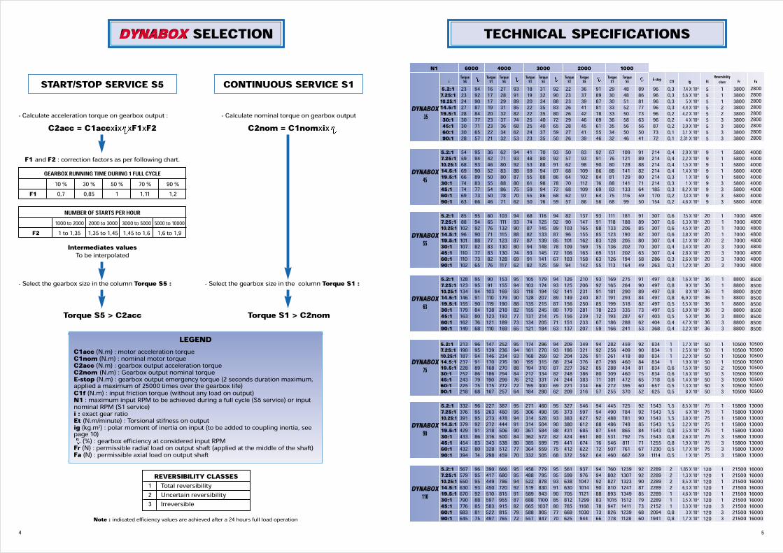
START/STOP SERVICE S5- Calculate acceleration torque on gearbox output :
C2acc = C1accxix xF1xF2
F1 and F2 : correction factors as per following chart.
Intermediates valuesTo be interpolated
- Select the gearbox size in the column Torque S5 :
Torque S5 > C2acc
- Select the gearbox size in the column Torque S1 :
Torque S1 > C2nom
- Calculate nominal torque on gearbox outputC2nom = C1nomxix
CONTINUOUS SERVICE S1
GEARBOX RUNNING TIME DURING 1 FULL CYCLE10 % 30 % 50 % 70 % 90 %
F1 0,7 0,85 1 1,11 1,2NUMBER OF STARTS PER HOUR
1000 to 2000 2000 to 3000 3000 to 5000 5000 to 10000F2 1 to 1,35 1,35 to 1,45 1,45 to 1,6 1,6 to 1,9
LEGENDC1acc (N.m) : motor acceleration torqueC1nom (N.m) : nominal motor torqueC2acc (N.m) : gearbox output acceleration torqueC2nom (N.m) : Gearbox output nominal torqueE-stop (N.m) : gearbox output emergency torque (2 seconds duration maximum,applied a maximum of 25000 times over the gearbox life)C1f (N.m) : input friction torque (without any load on output)N1 : maximum input RPM to be achieved during a full cycle (S5 service) or inputnominal RPM (S1 service)i : exact gear ratioEt (N.m/minute) : Torsional stifness on outputig (kg.m2) : polar moment of inertia on input (to be added to coupling inertia, seepage 10)(%) : gearbox efficiency at considered input RPMFr (N) : permissible radial load on output shaft (applied at the middle of the shaft)Fa (N) : permissible axial load on output shaft
REVERSIBILITY CLASSES1 Total reversibility2 Uncertain reversibility3 IrreversibleNote : indicated efficiency values are achieved after a 24 hours full load operation
DYNABOX SELECTION
5.2:1 23 94 16 27 93 18 31 92 22 36 91 29 48 89 96 0,3 7,4 X 10⁻⁶ 1 3800 7.25:1 23 92 17 28 91 19 32 90 23 37 89 30 48 86 96 0,3 5,6 X 10⁻⁶ 1 380010.25:1 24 90 17 29 89 20 34 88 23 39 87 30 51 81 96 0,3 5 X 10⁻⁶ 1 380014.5:1 27 87 19 31 85 22 35 83 26 41 81 33 52 77 96 0,3 4,4 X 10⁻⁶ 2 380019.5:1 28 84 20 32 82 22 35 80 26 42 78 33 50 73 96 0,2 4,2 X 10⁻⁶ 2 380030:1 30 77 23 37 74 25 40 72 29 46 69 36 58 63 96 0,2 4 X 10⁻⁶ 3 380045:1 30 71 23 36 68 25 40 65 28 45 61 35 56 56 87 0,2 3,9 X 10⁻⁶ 3 380060:1 30 65 22 34 62 24 37 59 27 41 55 34 50 50 73 0,1 3,1 X 10⁻⁶ 3 380090:1 28 57 21 32 53 23 35 50 26 39 46 32 46 41 72 0,1 2,31 X 10⁻⁶ 3 3800
TECHNICAL SPECIFICATIONS
DYNABOX35
5.2:1 54 95 36 62 94 41 70 93 50 83 92 67 109 91 214 0,4 2,9 X 10⁻⁵ 1 58007.25:1 59 94 42 71 93 48 80 92 57 93 91 76 121 89 214 0,4 2,2 X 10⁻⁵ 1 580010.25:1 68 93 46 80 92 53 88 91 62 98 90 80 128 88 214 0,4 1,5 X 10⁻⁵ 1 580014.5:1 69 90 52 83 88 59 94 87 68 109 86 88 141 82 214 0,4 1,4 X 10⁻⁵ 1 580019.5:1 66 89 50 80 87 55 88 86 64 102 84 81 129 80 214 0,3 1 X 10⁻⁵ 1 580030:1 74 83 55 88 80 61 98 78 70 112 76 88 141 71 214 0,3 1 X 10⁻⁵ 3 580045:1 74 77 54 86 75 59 94 72 68 109 69 83 133 64 185 0,3 8,2 X 10⁻⁶ 3 580060:1 69 73 50 78 70 55 86 68 62 97 64 75 116 59 170 0,2 7,3 X 10⁻⁶ 3 580090:1 63 66 46 71 62 50 76 59 57 86 56 68 99 50 154 0,2 4,6 X 10⁻⁶ 3 5800
DYNABOX45
5.2:1 85 95 60 103 94 68 116 94 82 137 93 111 181 91 307 0,6 7,5 X 10⁻⁵ 1 70007.25:1 88 94 65 111 93 74 125 92 90 147 91 118 188 89 307 0,6 5,3 X 10⁻⁵ 1 700010.25:1 102 92 76 132 90 87 145 89 103 165 88 133 206 85 307 0,6 4,5 X 10⁻⁵ 1 700014.5:1 96 90 71 115 88 82 133 87 96 155 85 123 190 82 307 0,6 3,8 X 10⁻⁵ 1 700019.5:1 101 88 77 123 87 87 139 85 101 162 83 128 205 80 307 0,4 3,1 X 10⁻⁵ 2 700030:1 107 82 83 130 80 94 148 78 109 169 75 136 202 70 307 0,4 3,4 X 10⁻⁵ 3 700045:1 110 77 83 130 74 93 145 72 106 163 69 131 202 63 307 0,4 2,8 X 10⁻⁵ 3 700060:1 110 73 82 128 69 91 141 67 103 158 63 126 194 58 286 0,3 2,6 X 10⁻⁵ 3 700090:1 102 65 76 117 62 82 125 59 94 142 55 113 164 49 263 0,3 1,2 X 10⁻⁵ 3 7000
DYNABOX55
5.2:1 128 95 90 153 95 105 179 94 126 210 93 169 275 91 497 0,8 1,6 X 10⁻⁴ 1 88007.25:1 123 95 91 155 94 103 174 93 125 206 92 165 264 90 497 0,8 9 X 10⁻⁵ 1 880010.25:1 134 94 103 169 93 118 194 92 141 231 91 181 290 89 497 0,8 8 X 10⁻⁵ 1 880014.5:1 146 91 110 179 90 128 207 89 149 240 87 191 293 84 497 0,8 6,9 X 10⁻⁵ 1 880019.5:1 155 90 119 190 88 135 215 87 156 250 85 199 318 82 497 0,5 5,5 X 10⁻⁵ 1 880030:1 179 84 138 218 82 155 245 80 179 281 78 223 335 73 497 0,5 5,9 X 10⁻⁵ 3 880045:1 163 80 123 193 77 137 214 75 156 239 72 193 287 67 403 0,5 5 X 10⁻⁵ 3 880060:1 162 76 121 189 73 134 205 71 151 233 67 186 288 62 404 0,4 4,7 X 10⁻⁵ 3 880090:1 149 68 110 169 65 121 184 63 137 207 59 166 241 53 368 0,4 3,2 X 10⁻⁵ 3 8800
DYNABOX63
5.2:1 213 96 147 252 95 174 296 94 209 349 94 282 459 92 834 1 3,7 X 10⁻⁴ 1 105007.25:1 190 95 139 236 94 161 270 93 196 321 92 256 409 90 834 1 2,5 X 10⁻⁴ 1 1050010.25:1 187 94 146 234 93 168 269 92 204 326 91 261 418 88 834 1 2,2 X 10⁻⁴ 1 1050014.5:1 237 91 170 276 90 195 315 88 234 376 87 298 460 84 834 1 1,9 X 10⁻⁴ 1 1050019.5:1 228 89 168 270 88 194 310 87 227 362 85 288 434 81 834 0,6 1,5 X 10⁻⁴ 2 1050030:1 252 86 186 294 84 212 334 82 248 386 80 309 460 75 834 0,6 1,6 X 10⁻⁴ 3 1050045:1 243 79 190 299 76 212 331 74 244 383 71 301 472 65 718 0,6 1,4 X 10⁻⁴ 3 1050060:1 225 75 175 272 72 195 300 69 221 334 66 272 395 60 657 0,5 1,3 X 10⁻⁴ 3 1050090:1 218 68 167 257 64 184 280 62 209 316 57 255 370 52 625 0,5 8 X 10⁻⁵ 3 10500
DYNABOX75
5.2:1 332 96 227 387 95 271 460 95 327 546 94 445 725 92 1543 1,5 8,5 X 10⁻⁴ 1 158007.25:1 376 95 263 460 95 306 490 95 373 597 94 490 784 92 1543 1,5 6 X 10⁻⁴ 1 1580010.25:1 391 95 273 478 94 314 528 93 383 627 92 488 781 90 1543 1,5 3,8 X 10⁻⁴ 1 1580014.5:1 379 92 272 444 91 314 504 90 380 612 88 486 748 85 1543 1,5 3,2 X 10⁻⁴ 1 1580019.5:1 429 91 318 506 90 367 584 88 431 685 87 544 865 84 1543 0,8 2,5 X 10⁻⁴ 1 1580030:1 433 86 316 500 84 362 572 82 424 661 80 531 792 75 1543 0,8 2,6 X 10⁻⁴ 3 1580045:1 454 83 343 538 80 385 599 79 441 674 76 546 811 71 1255 0,8 1,9 X 10⁻⁴ 3 1580060:1 432 80 328 512 77 364 559 75 412 622 72 507 761 67 1230 0,5 1,7 X 10⁻⁴ 3 1580090:1 394 74 298 459 70 332 505 68 372 562 64 460 667 59 1114 0,5 1 X 10⁻⁴ 3 15800
DYNABOX90
5.2:1 567 96 390 666 95 458 779 95 561 937 94 760 1239 92 2289 2 1,85 X 10⁻³ 1 215007.25:1 579 95 417 680 95 488 795 95 599 976 94 802 1307 92 2289 2 1,3 X 10⁻³ 1 2150010.25:1 650 95 449 786 94 522 878 93 638 1047 92 827 1323 90 2289 2 8,5 X 10⁻⁴ 1 2150014.5:1 630 93 450 720 92 519 830 91 630 1014 90 810 1247 87 2289 2 6,3 X 10⁻⁴ 1 2150019.5:1 670 92 510 815 91 589 943 90 705 1121 88 893 1349 85 2289 1 4,6 X 10⁻⁴ 1 2150030:1 790 88 597 955 87 688 1100 85 812 1299 83 1015 1512 79 2289 1 3,5 X 10⁻⁴ 1 2150045:1 776 85 583 915 82 665 1037 80 765 1168 78 947 1411 73 2152 1 3,3 X 10⁻⁴ 3 2150060:1 683 81 522 815 79 588 905 77 669 1030 73 826 1239 68 2094 0,8 3 X 10⁻⁴ 3 2150090:1 645 75 497 765 72 557 847 70 625 944 66 778 1128 60 1941 0,8 1,7 X 10⁻⁴ 3 21500
DYNABOX110
N1 6000TorqueS5 TorqueS1 TorqueS5 TorqueS1 TorqueS5 TorqueS1 TorqueS5 TorqueS1 TorqueS5 E-stop C1f ig Et Fr FaReversibilityclassi
4000 3000 2000 1000
5
555555555999999999202020202020202020363636363636363636505050505050505050757575757575757575120120120120120120120120120
280028002800280028002800280028002800400040004000400040004000400040004000480048004800480048004800480048004800850085008500850085008500850085008500105001050010500105001050010500105001050010500130001300013000130001300013000130001300013000160001600016000160001600016000160001600016000
6
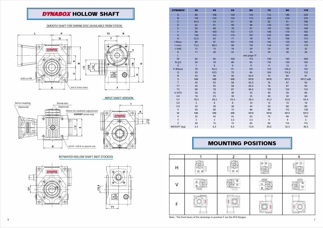
DYNABOX HOLLOW SHAFT
EXPERT
EXPERT
EXPERT
(EXPERT version only)
PQ
L
(x4)S on ∅M
Servo coupling(Optional)
Shrink disc(Optional)
A (x4) ∅ O thru holes
CX B
∅V
∅U3
∅U
T2 RT
Y
∅N G
H
F
INPUT SHAFT VERSION
(x4) W + (x4) W on opposite side
Z E
D
IK
∅J
KEYWAYED HOLLOW SHAFT (NOT STOCKED)
U1 U2
T1
∅U 4
Shims for backlash adjustment
SMOOTH SHAFT FOR SHRINK DISC (AVAILABLE FROM STOCK)
7Note : The front faces of the drawings in position F are the B14 flanges.
MOUNTING POSITIONS21 3 4
H
V
F EXPERT
EXPERT EXPERT
EXPERT
DYNABOX 35 45 55 63 75 90 110A 86 108 120 134 172 186 220B 110 135 155 173 208 234 276C 44.5 53 61 66 82 91 108D 62 81 90 98 136 141 175E 56 68 78 91 110 130 140F 86 100 112 127 148 170 182G 126 153 175 197 232 264 306H 52,5 62 71 78 94 106 123I Maxi 80 97 107 120 145 159 182I mini 73,5 89,5 99 110 134 147 170J (h6) 12 15 18 20 24 28 32K 17 20 22 24 28 30 36L see page 11M 65 85 100 115 130 165 200N (j7) 50 70 80 95 110 130 165O 7 9 9 11 11 13 13P (Maxi) 70 83,5 91 101 124 136,5 152Q 55 67,5 75 84 104 114,5 132R 43 50 56 63,5 74 85 91S M6 M8 M8 M10 M10 M12 M12 (x8)T 45 52 58 65,5 76 87 93T1 45 52 58 65,5 76 87 93T2 69 78 87 96,5 110 124 133U (H7) 20 25 30 35 40 50 60U4 16 25 30 35 40 50 60U1 18,3 28,3 33,3 38,3 43,3 53,8 64,4U2 5 8 8 10 12 14 18U3 24 30 36 44 50 68 80V 50 60 72 80 90 115 138W M6 M8 M8 M10 M10 M12 M12X 35 45 55 63 75 90 110Y 3 3 3,5 3,5 4 4 5Z 58 75 75 85 95 115 115WEIGHT (kg) 3,4 6,2 8,5 13,9 20,5 32,5 46,5
9
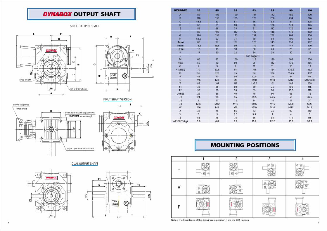
DYNABOX 35 45 55 63 75 90 110A 86 108 120 134 172 186 220B 110 135 155 173 208 234 276C 44.5 53 61 66 82 91 108D 62 81 90 98 136 141 175E 56 68 78 91 110 130 140F 86 100 112 127 148 170 182G 126 153 175 197 232 264 306H 52,5 62 71 78 94 106 123I Maxi 80 97 107 120 145 159 182I mini 73,5 89,5 99 110 134 147 170J (h6) 12 15 18 20 24 28 32K 17 20 22 24 28 30 36L see page 11M 65 85 100 115 130 165 200N(j7) 50 70 80 95 110 130 165O 7 9 9 11 11 13 13P (Maxi) 70 83,5 91 101 124 136,5 152Q 55 67,5 75 84 104 114,5 132R 43 50 56 63,5 74 85 91S M6 M8 M8 M10 M10 M12 M12 (x8)T 83 107 118 135,5 151 187 208T1 38 55 60 70 75 100 115T2 35 50 55 65 70 95,5 110U (h6) 25 35 40 45 50 65 75U1 21 30 35 39,5 44,5 58 67,5U2 8 10 12 14 14 18 20U3 M10 M12 M16 M16 M16 M20 M20W M6 M8 M8 M10 M10 M12 M12X 35 45 55 63 75 90 110Y 3 3 3,5 3,5 4 4 5Z 58 75 75 85 95 115 115WEIGHT (kg) 3,6 6,8 9,2 15,2 22,2 35,1 50,3
Note : The front faces of the drawings in position F are the B14 flanges.
MOUNTING POSITIONS21 3 4
H
V
F EXPERT
EXPERT EXPERT
EXPERT
8
DYNABOX OUTPUT SHAFT
(EXPERT version only)
SINGLE OUTPUT SHAFT
DUAL OUTPUT SHAFT
PQ
L
CX
(x4)S on ∅M
A
B
U2
U3
U1
∅N
∅U
F
EXPERT
INPUT SHAFT VERSIONI
K
∅J
EXPERT
(x4) W + (x4) W on opposite side
D
w Z E
T1T2 T2
T T
∅U
∅U
U2
U3
U1
EXPERT
R T
GH
YT2
Servo coupling(Optional)
(x4) ∅ O thru holes
Shims for backlash adjustement

10
CONNECTING KIT DYNABOX -SERVOMOTORTORSION STIFF COUPLINGS
CONNECTING FLANGE
Coupling reference AM N° 5 AM N° 10 AM N° 15 AM N° 30 AM N° 60 AM N° 80x servo shaft and DYNABOX shaft mm <x16 <x24 <x28 <x32 <x35 <x42Servo nominal torque Nm 5 10 15 30 60 80Servo peak torque Nm 7,5 15 22,5 45 90 120x D mm 32 40 49 55 66 82L mm 42 46 60 70 81 94Polar moment of inertia 10-3kgm2 0,01 0,02 0,05 0,09 0,18 0,54Torsional stiffness Nm/mn 2 2,6 6 11 22 37Tightening torque of campling screws Nm 4 4,5 9 14 35 70
Specify the coupling reference and the servo shaft xwhen ordering.Exemple : AM n° 15 x 14.
To calculate the input total inertia, add the couplinginertia to the gearbox inertia (page 5).
Select the required flange on page 11. If no flange can be found in the list, supply thedimensions from A to Z, or supply the servo reference
∅ D
L
∅A B
LC
EXPERT
w Z
(x4)E on ∅D
11
DYNABOX Reference A B C mini D E L ZBM-F63/40 40 4 31 63 M4 111 65BM-F70/50 50 4 34 70 M4 114 65BM-F75/60 60 4 34 75 M5 114 65BM-F90/70 70 4 44 90 M5 124 90BM-F95/50 50 4 34 95 M6 114 90BM-F100/80 80 4 44 100 M6 124 90BM-F115/95 95 5 44 115 M8 124 118BM-F130/95 95 5 54 130 M8 134 118BM-F130/110 110 5 54 130 M8 134 118BM-F145/110 110 6,5 64 145 M8 144 118BM-F70/50 50 4 34.5 70 M4 131,5 81BM-F75/60 60 4 34.5 75 M5 131,5 81BM-F90/70 70 4 44.5 90 M5 141,5 91BM-F95/50 50 4 34.5 95 M6 131,5 91BM-F100/80 80 4 44.5 100 M6 141,5 91BM-F115/95 95 5 44.5 115 M8 141,5 115BM-F130/95 95 5 54.5 130 M8 151,5 115BM-F130/110 110 5 54.5 130 M8 151,5 115BM-F145/110 110 6.5 64.5 145 M8 161,5 140BM-F165/110 110 6,5 54.5 165 M10 151,5 140BM-F165/130 130 6,5 54.5 165 M10 151,5 140BM-F70/50 50 4 35 70 M4 142 81BM-F75/60 60 4 35 75 M5 142 81BM-F90/70 70 4 45 90 M5 152 91BM-F95/50 50 4 35 95 M6 142 91BM-F100/80 80 4 45 100 M6 152 91BM-F115/95 95 5 45 115 M8 152 115BM-F130/95 95 5 55 130 M8 162 115BM-F130/110 110 5 55 130 M8 162 115BM-F145/110 110 6,5 65 145 M8 172 140BM-F165/110 110 6,5 55 165 M10 162 140BM-F165/130 130 6,5 55 165 M10 162 140BM-F70/50 50 4 36 70 M4 156 102BM-F75/60 60 4 36 75 M5 156 102BM-F90/70 70 4 42 90 M5 162 102BM-F100/80 80 4 42 100 M6 162 102BM-F115/95 95 5 42 115 M8 162 115BM-F130/95 95 5 52 130 M8 172 115BM-F130/110 110 5 52 130 M8 172 115BM-F145/110 110 6.5 62 145 M8 182 140BM-F165/110 110 6,5 52 165 M10 172 140BM-F165/130 130 6,5 52 165 M10 172 140BM-F200/114,3 114,3 6,5 82 200 M10 202 185BM-F215/130 130 6,5 62 215 M12 182 185BM-F215/180 180 6,5 62 215 M12 182 185BM-F70/50 50 4 40 70 M4 185 102BM-F75/60 60 4 40 75 M5 185 102BM-F90/70 70 4 46 90 M5 191 102BM-F100/80 80 4 46 100 M6 191 102BM-F115/95 95 5 46 115 M8 191 115BM-F130/95 95 5 56 130 M8 201 115BM-F130/110 110 5 56 130 M8 201 115BM-F145/110 110 6,5 66 145 M8 211 140BM-F165/110 110 6,5 56 165 M10 201 140BM-F165/130 130 6,5 56 165 M10 201 140BM-F200/114,3 114,3 6,5 86 200 M10 231 185BM-F215/130 130 6,5 66 215 M12 211 185BM-F215/180 180 6,5 66 215 M12 211 185BM-F100/80 80 4 46.5 100 M6 205,5 123BM-F115/95 95 5 46.5 115 M8 205,5 123BM-F130/95 95 5 56.5 130 M8 215,5 123BM-F130/110 110 5 56.5 130 M8 215,5 123BM-F145/110 110 6,5 66.5 145 M8 225,5 140BM-F165/110 110 6,5 56.5 165 M10 215,5 140BM-F165/130 130 6,5 56.5 165 M10 215,5 140BM-F200/114,3 114,3 6,5 86.5 200 M10 245,5 185BM-F215/130 130 6,5 66.5 215 M12 225,5 185BM-F215/180 180 6,5 66.5 215 M12 225,5 185BM-F300/250 250 6,5 88.5 300 M14 247,5 260BM-F100/80 80 4 47 100 M6 229 123BM-F115/95 95 5 47 115 M8 229 123BM-F130/95 95 5 57 130 M8 239 123BM-F130/110 110 5 57 130 M8 239 123BM-F145/110 110 6,5 67 145 M8 249 140BM-F165/110 110 6,5 57 165 M10 239 140BM-F165/130 130 6,5 57 165 M10 239 140BM-F200/114,3 114,3 6,5 87 200 M10 269 185BM-F215/130 130 6,5 67 215 M12 249 185BM-F215/180 180 6,5 67 215 M12 249 185BM-F300/250 250 6,5 89 300 M14 271 260
35
45
55
63
75
90
110
12
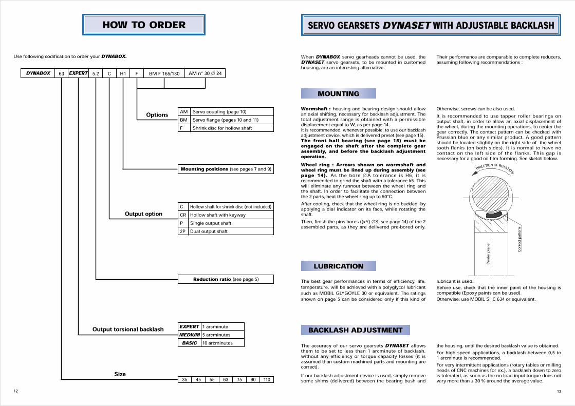
HOW TO ORDERUse following codification to order your DYNABOX.
DYNABOX 63 5.2EXPERT C H1 F AM n° 30 x 24BM F 165/130
AM Servo coupling (page 10)BM Servo flange (pages 10 and 11)F Shrink disc for hollow shaft
Mounting positions (see pages 7 and 9)
Reduction ratio (see page 5)
C Hollow shaft for shrink disc (not included)CR Hollow shaft with keywayP Single output shaft2P Dual output shaft
EXPERT 1 arcminuteMEDIUM 5 arcminutesBASIC 10 arcminutes
35 45 55 63 75 90 110
Options
Output option
Output torsional backlash
Size13
SERVO GEARSETS DYNASET WITH ADJUSTABLE BACKLASH
MOUNTING
When DYNABOX servo gearheads cannot be used, theDYNASET servo gearsets, to be mounted in customedhousing, are an interesting alternative.Their performance are comparable to complete reducers,assuming following recommendations :
Wormshaft : housing and bearing design should allowan axial shifting, necessary for backlash adjustment. Thetotal adjustment range is obtained with a permissibledisplacement equal to W, as per page 14.It is recommended, whenever possible, to use our backlashadjustment device, which is delivered preset (see page 15).The front ball bearing (see page 15) must beengaged on the shaft after the complete gearassembly, and before the backlash adjustmentoperation.Wheel ring : Arrows shown on wormshaft andwheel ring must be lined up during assembly (seepage 14). As the bore xA tolerance is H6, it isrecommended to grind the shaft with a tolerance k5. Thiswill eliminate any runnout between the wheel ring andthe shaft. In order to facilitate the connection betweenthe 2 parts, heat the wheel ring up to 50°C.After cooling, check that the wheel ring is no buckled, byapplying a dial indicator on its face, while rotating theshaft.Then, finish the pins bores ((xY) xS, see page 14) of the 2assembled parts, as they are delivered pre-bored only.
Otherwise, screws can be also used.It is recommended to use tapper roller bearings onoutput shaft, in order to allow an axial displacement ofthe wheel, during the mounting operations, to center thegear correctly. The contact pattern can be checked withPrussian blue or any similar product. A good patternshould be located slightly on the right side of the wheeltooth flanks (on both sides). It is normal to have nocontact on the left side of the flanks. This gap isnecessary for a good oil film forming. See sketch below.
LUBRICATIONThe best gear performances in terms of efficiency, life,temperature, will be achieved with a polyglycol lubricantsuch as MOBIL GLYGOYLE 30 or equivalent. The ratingsshown on page 5 can be considered only if this kind of
lubricant is used.Before use, check that the inner paint of the housing iscompatible (Epoxy paints can be used).Otherwise, use MOBIL SHC 634 or equivalent.
BACKLASH ADJUSTMENTThe accuracy of our servo gearsets DYNASET allowsthem to be set to less than 1 arcminute of backlash,without any efficiency or torque capacity losses (it isassumed than custom machined parts and mounting arecorrect).If our backlash adjustment device is used, simply removesome shims (delivered) between the bearing bush and
the housing, until the desired backlash value is obtained.For high speed applications, a backlash between 0,5 to1 arcminute is recommended.For very intermittent applications (rotary tables or millingheads of CNC machines for ex.), a backlash down to zerois tolerated, as soon as the no load input torque does notvary more than ± 30 % around the average value.
Center
plane
Correct
pattern
DIRECTION OF ROTATION

14
BACKLASH ADJUSTMENT DEVICE FOR DYNASET
15
35 45 55 63 75 90 110D (h6) 42 47 52 62 72 72 80Y Maxi 43,5 54 58 65 84 94 110Y Mini 38,5 49 53 59 78 88 104P Maxi 69 83 91 100 121 131,5 150P Mini 64 78 86 94 115 125,5 144Q 55 67,5 75 84 104 114,5 132R 9 10,5 10 10 11 11 12S M6 M6 M8 M8 M10 M10 M10T 55 65 66 80 90 100 100Z 58 75 75 95 95 115 115X 16004 6005 6205 6206 6207 6207 6208
The backlash adjustment device is delivered mounted and preset.Bearings are factory preloaded.Backlash adjustment is operated with shims located between the housing and the bearingbush.
Use following codification to order your DYNASET.
PQ
R w Z
∅D
Y BACKLASH REDUCTION DIRECTION
O ring (supplied)Adjustment shims (supplied)
X front bearing (supplied)4 Allen screws (not supplied) S equally spaced on ∅ T
Axe rou
e
DYNASET
HOW TO ORDERDYNASET 63 90 ADJ
Reduction ratio (see page 5)35 45 55 63 75 90 110
Backlash adj. device (see page 15)Option
Size
SERVO GEARSET DYNASET
14
35 45 55 63 75 90 110A (H6) 32 47 52 71 82 103 136B Maxi 55 78 92 108 124,5 157,4 191,4C 33 38 43 46 52 57 60D 63,5 80 85 97 126,5 144 173E 14 19 28 27 32 38 40F 26,5 32 37 40,5 47,5 51 49G 32 40 42 47,5 63 70 82H Maxi 31 37,6 43,7 49,7 54,7 67,5 75,5I Maxi 13,5 17,3 20,5 23,4 26,3 33,2 36,1J (h6) 12 15 18 20 24 28 32K 17 20 22 24 28 28 36L 8 9 10 11 13 14 15M M15 x 1,00 M17 x 1,00 M20 x 1,00 M25 x 1,50 M 30 x 1,50 M35 x 1,50 M40 x 1,50N (k6) 15 17 20 25 30 35 40O 20 24 26 32 37 42 47P Maxi 24,7 26,5 32,5 37,1 44,2 50,8 56,5Q 24 30 30 35 42 42 47R (k6) 20 25 25 30 35 35 40S 3,5 4 4 4 5 6 8T 38 54,5 60 79 91 113 148U 19 23,9 23,9 28,6 33 33 37,5U1 1,3 1,3 1,3 1,6 1,6 1,6 1,85V (h11) 20 25 25 30 35 35 40W 5 5 5 6 6 6 6X 35 45 55 63 75 90 110Y 4 6 8 10 10 10 10Z 8 12 15 16 17 17 18
C D F KI Z
U1HL
X
∅ O
∅ R
∅ Q
∅ U
∅ P
∅ M
G
∅ V
∅ J
W
E
∅ A
∅ B
∅ N
Line up arrows when assembling
(xY) ∅ S on ∅ T
Surfaces marked can be referred to for checking runnout
- 0- 2
+ 0,05/
+ 0,1
W 0,1
DYNASET