Embed Size (px)
Citation preview

Reduction of Dielectric Hysteresis in Multilayered Films viaNanoconfinementMatthew Mackey,† Donald E. Schuele,† Lei Zhu,†,* Lionel Flandin,‡ Mason A. Wolak,§ James S. Shirk,§
Anne Hiltner,†,∥ and Eric Baer†,*†Department of Macromolecular Science and Engineering, Case Western Reserve University, Cleveland, Ohio 44106, United States‡LEPMI, UMR 5279, CNRS, Universite ́ de Savoie, F-73376 Le Bourget Du Lac Cedex, France§US Naval Research Laboratory, Washington, D.C. 20375, United States
ABSTRACT: Micro/nanolayer coextrusion was used tofabricate polycarbonate (PC)/poly(vinylidene fluoride)(PVDF) layered films with significantly reduced dielectriclosses while maintaining high energy density. The high-fieldpolarization hysteresis was characterized for layered films as afunction of PVDF layer thickness (6000 to 10 nm) andcomposition (10 to 70 vol % PVDF), and was found todecrease with decreasing layer thickness and PVDF content.To gain a mechanistic understanding of the layer thickness (ornanoconfinement) effect, wide-angle X-ray diffraction, polar-ized Fourier transform infrared spectroscopy, and broadband dielectric spectroscopy were employed. The results revealed thatcharge migration, instead of dipole flipping, was responsible for the hysteresis in multilayered films. The absence of PVDF dipole-flipping was attributed to the nonuniform electric field distribution in the layered structure, where the field in PVDF layers werecalculated to be significantly lower than that in PC layers due to large contrast in dielectric constant (∼3 for PC versus ∼12 forPVDF). The charges were likely to be impurity ions in the form of catalyst residue or surfactants from suspensionpolymerization. The characteristics of the dielectric spectroscopy relaxation indicated that ions mostly existed in the PVDF layers,and PC/PVDF interfaces prevented them from entering adjacent layers. Therefore, as the layer thickness decreases to nanometerscales, the amount of ion movement, dielectric loss, and hysteresis were decreased. This study provides clear evidence of thenanoconfinement effect in multilayered films, which advantageously decreases the hysteresis loss.
■ INTRODUCTIONCapacitors are vital in nearly all microelectronics and electronicdevices, ranging from cell phones and computers to automotivevehicles and power systems.1−3 The common uses includesignal coupling/decoupling and filtering, high current sourcing,power conditioning, and pulsed power (or energy storage).Currently, there are several important motivations fordeveloping dielectric capacitors with increased energy densityand low loss. First, it is necessary for capacitors to keep pacewith the global trend of electronics miniaturization. Second,with the drive to decrease fossil fuel dependence, compact/lightweight and reliable capacitors are required for applicationssuch as hybrid electric vehicles4 and grid converters forrenewable energy sources.5 The maximum energy density thatcan be stored in an insulating material is proportional to thedielectric constant times the square of the breakdown strength.6
Therefore, highly insulating materials with both a highdielectric constant and high breakdown strength are desired.To maintain high performance and reliability, it is alsonecessary to maintain low losses (i.e., low-field dissipationfactor and high-field hysteresis loss) since losses reduce thedischarged energy density, cause dielectric heating, and limitthe frequency response of the capacitor.1
Polymer dielectrics have recently attracted substantialresearch interest because of their excellent manufacturing/processing advantages and electrical insulating properties. Froma manufacturing point of view, polymers are easy to produceand process on a large scale, which makes them inexpensive.They are also lightweight with good mechanical properties.Regarding their electrical properties, polymers generally have ahigh breakdown strength and low losses.7 Two widely usedstate-of-the-art polymer dielectrics are biaxially orientedpolypropylene (BOPP) and poly(ethylene terephthalate)(PET), which have the following measured properties: materiallevel energy density of 5−6 J/cm3 at breakdown, dielectricconstant of 2−3, breakdown strength of 600−700 MV/m, andtan δ of 0.0003−0.002.2In spite of extensive and far-reaching research efforts,
realization of high performance dielectric materials withincreased energy density and low loss is still an importantgoal. One method of improving the energy density andperformance is to combine two or more different materials byblending or in situ polymerization. Several common fillers for
Received: October 12, 2011Revised: January 9, 2012Published: February 3, 2012
Article
pubs.acs.org/Macromolecules
© 2012 American Chemical Society 1954 dx.doi.org/10.1021/ma202267r | Macromolecules 2012, 45, 1954−1962
high energy density polymer nanodielectrics include bariumtitanate,8−12 lead zirconate titanate,13 and titanium dioxide.14,15
Other techniques aim to modify BOPP (or PET)16 orsynthesize specialized copolymers and terpolymers, e.g.,poly(vinylidene fluoride-co-chlorotrifluoroethylene) [P(VDF-CTFE)] and P(VDF-co-trifluoroethylene-co-chlorotrifluoro-ethylene) [P(VDF-TrFE-CTFE)].6,17,18 Often, the approachesproduce an enhancement in one of the properties (e.g., energydensity) but a reduction in another (e.g., dielectric andhysteresis losses). Other common issues include commercialviability, scale-up, cost, and mechanical/thermal stability, whichare difficult for newly synthesized materials.19,20
To improve electrical properties while maintaining mechan-ical integrity and commercial viability requirements, we haveused the novel polymer processing technique of micro/nanolayer coextrusion to produce layered structures. Thisprocessing technique includes the combination of 2 or 3polymers in an ABABABAB, ABCABCABC, or ABCBABCBconfiguration, creating films with 2 to 4096 layers and layerthicknesses ranging from tens of micrometers down to less than10 nm.21 Prior research has shown that useful changes occur inthe mechanical, optical,22−24 and transport properties,25 as thelayer thickness is reduced to nanometer scales. From adielectric standpoint, analogous changes are expected andelectrical properties can be optimized by independently varyingthe layer thickness and film composition. The layered filmcontaining one high dielectric constant material [P(VDF-co-hexafluoropropylene), P(VDF-HFP)] and one high breakdownstrength material [polycarbonate (PC)] has been previouslystudied and shown to provide significant enhancements inbreakdown strength.26,27
In this report, the nanoconfinement effect from multilayeringof PC and PVDF on reducing low-field dielectric and high-fieldhysteresis losses is explored. It is found that ion migration inPVDF layers, rather than PVDF dipole switching, is responsiblefor both dielectric and hysteresis losses. Note that the PVDF issynthesized by suspension polymerization. Therefore, the ionicimpurity should originate from surfactant residue. On the basisof a simulation study using the diffusion model by Sawada,28,29
the diffusion coefficient and concentration of the impurity ionswere estimated to be 2 × 10⁻¹³ m2/s and <1 ppm (by weight),respectively. By decreasing the PVDF layer thickness down to afew tens of nanometers, both low and high field losses can besignificantly reduced. On the basis of this finding, thesynergistic effect of thin layers and additives on the physicalproperties may open a door to new engineering practice inmany other applications.
■ EXPERIMENTAL SECTIONMaterials. Two polymers were used in this study, one for its high
breakdown strength and the other for its high dielectric constant. PC,Calibre 200−6 with a molecular weight of 24 500 g/mol from DowChemical Company, was chosen as the high breakdown strengthmaterial. PVDF homopolymer, Solef 6010 with a molecular weight of64 000 g/mol from Solvay Solexis, was chosen as the high dielectricconstant material. A set of PC/PVDF multilayered films was producedusing microlayer coextrusion (Table 1). The films were coextrudedwith sacrificial polyethylene (PE) skin layers on both sides of thelayered film in order to improve the film surface smoothness,handleability, and immunity to damage. This skin was peeled offbefore any measurements were carried out. In addition to the 50/50PC/PVDF films in Table 1, compositions of 90/10, 70/30, 30/70, and10/90 were also produced. A coextrusion temperature of 250 °C waschosen based on the rheological compatibility of the two polymers.The polymer rheology was characterized using a melt flow indexer(MFI), on Kayeness Galaxy 1, at a shear rate that is similar to extrusionconditions (10 s−1). Prior to processing the PC resin, it was dried in avacuum oven at 80 °C for 48 h.
Atomic Force Microscopy (AFM). The layered film cross sectionswere imaged using AFM. The samples were prepared by embeddingthe films in epoxy and microtoming at −40 °C with an ultramicrotome(Leica EM FC6). Phase and height images of the cross sections wererecorded simultaneously at ambient temperature in air using thetapping mode of a Nanoscope IIIa MultiMode scanning probe (DigitalInstruments, Santa Barbara, CA).
Dielectric Hysteresis Measurements. Electric displacement−electric field (D−E) hysteresis measurements were carried out on aPremiere II ferroelectric tester from Radiant Technologies, Inc. Theapplied voltage was a bipolar triangular waveform at 1 Hz. Anelectrostatic sandwich technique was used to apply electrodes, whichwere 5.8 μm metalized BOPP films, on both sides of the film.30 An 80μm thick Kapton mask with a 1 cm diameter hole was used to controlthe area under high fields. In each sample, electric fields from 100 to500 MV/m were applied to the sample in 50 MV/m increments. Thiselectrostatic sandwich setup performed better without any insulatingoils because the oil could prevent two metalized BOPP films fromcoming together and establishing a tight contact with the test film. Toensure safety, all high field measurements were remotely controlledwith a computer.
X-ray Diffraction. Wide-angle X-ray diffraction (WAXD) patternswere obtained by aligning the incident X-ray beam parallel to theextrusion direction (ED) of the film. The measurements wereperformed on a Rigaku MicroMax-002+ diffractometer at 45 kV and0.88 mA. A Confocal Max-Flux optics was used with a sealed tubemicrofocus X-ray source, giving a highly focused beam ofmonochromatic Cu Kα radiation (λ = 0.154 nm). The sample-to-detector distance was 140 mm, and the diffraction angle was calibratedusing a CaF2 standard. The patterns were collected using an imageplate with a 50 μm pixel size.
Electric Field Dependent Polarized Fourier TransformInfrared (FTIR). Polarized FTIR under electric field was carried outon a Nexus 870 FTIR ESP from Nicolet with the polarizer fixed at the
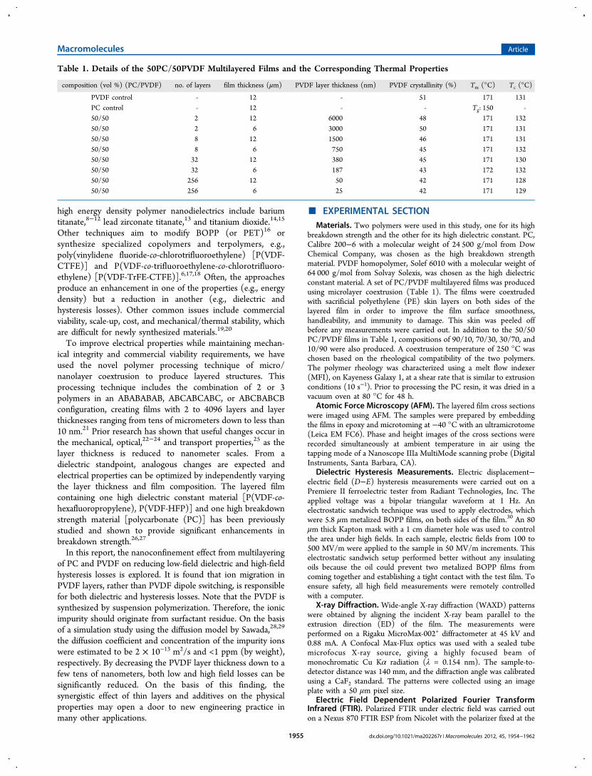
Table 1. Details of the 50PC/50PVDF Multilayered Films and the Corresponding Thermal Properties
composition (vol %) (PC/PVDF) no. of layers film thickness (μm) PVDF layer thickness (nm) PVDF crystallinity (%) Tm (°C) Tc (°C)
PVDF control - 12 - 51 171 131PC control - 12 - - Tg: 150 -50/50 2 12 6000 48 171 13250/50 2 6 3000 50 171 13150/50 8 12 1500 46 171 13150/50 8 6 750 45 171 13250/50 32 12 380 45 171 13050/50 32 6 187 43 172 13250/50 256 12 50 42 171 12850/50 256 6 25 42 171 129
Macromolecules Article
dx.doi.org/10.1021/ma202267r | Macromolecules 2012, 45, 1954−19621955

perpendicular configuration, i.e., the angle between the film stretchingdirection and the polarizing light was 90°. Films were stretched aboutfour times at 120 °C using a homemade uniaxial stretching machine ina Blue-M gravity oven. Carbon electrodes were evaporated onto bothsides of the film using a Denton Bench Top Turbo III high vacuumevaporator. The thickness of carbon electrodes was optimized so thatthe resulting resistance was several kΩ with a baseline transmittance of80−90%.31−33 High electric fields were supplied with a MatsusadaAMT-20B10−B high voltage amplifier.Dielectric Spectroscopy. Broadband dielectric spectroscopy
measurements were performed on a Novocontrol unit (0.001 Hz to100 kHz, 25 to 200 °C) under a vacuum of 40 mTorr. Sample wasprepared by evaporating 30 nm thick aluminum electrodes with 1 cmdiameter to both sides of the test film.
■ RESULTS AND DISCUSSIONEffect of Layering on High-Field Polarization Hyste-
resis. The layer integrity and uniformity were examined usingphase contrast atomic force microscopy (AFM), as shown inFigure 1. There were no structural defects in the multilayered
films such as layer breakup or interlayer connection, which isthe advantage of forced assembly using microlayer coex-trusion.21,25 The layer thickness and standard deviation weredetermined from the AFM images in Figure 1 to be 6200 ± 780nm, 1600 ± 160 nm, 400 ± 90 nm, and 50 ± 10 nm for 50PC/50PVDF 2-, 8-, 32-, and 256-layer films, respectively. Thesemeasured thicknesses are in good agreement with the nominallayer thicknesses given in Table 1 in the Experimental Section.Here, an individual film is named as xxPC/yyPVDF (LL μm/ZZ nm), where xx and yy are volume percentages of PC andPVDF, LL is the total film thickness, and ZZ is the PVDF layerthickness. This nomenclature will be used throughout thepaper.To determine the effect of layer confinement on D−E
hysteresis, measurements were carried out on PC/PVDF
layered films and controls. For clarity, a single field sweep at400 MV/m is shown for the two controls. For the layered films,field sweeps at 100, 200, 300, and 400 MV/m are shown. ThePC control exhibited low hysteresis, which was expected forlinear dielectric materials, and the PVDF control had a largehysteresis loop with dipole saturation at high fields, which wastypical of ferroelectric materials (Figure 2a).34 The hysteresis
behavior of layered films showed intermediate levels of electricdisplacement relative to the controls, i.e., larger loops than PCbut no dipole saturation at high fields (400−500 MV/m) asseen for the PVDF control (Figure 2).The effects of layer thickness, electric field, and film
composition on dielectric hysteresis were studied for the PC/PVDF layered films. In parts b−d of Figure 2, reducing layerthickness caused a substantial decrease in the hysteresis. Theseresults were quantified and generalized by calculating thehysteresis loop area as a function of layer thickness for severaldifferent compositions and electric fields (Figure 3). It wasfound that thinner layers had a beneficial effect on thehysteresis at different electric fields (300−500 MV/m) andcompositions (10−70 vol % PVDF) (see Figure 3). Whenindependently studying the effects of composition and electricfield on hysteresis, the hysteresis loop area increased withincreasing the PVDF content and electric field. When thePVDF volume fraction was 90 vol %, the high-field hysteresisloop substantially opened up and became similar to that ofPVDF in Figure 2A (data not shown), suggesting that when thePC layer thickness was too thin as compared to the thickness ofPVDF, the PC layers had almost no effect on reducing thehysteresis loss. Therefore, no comparison was made for PC/PVDF 10/90 multilayered films in Figure 3.The above results provided us the following information.
First, the composition effect indicated that PVDF layers wereresponsible for the hysteresis, which was consistent with thelarge hysteresis of the PVDF control. Regarding the effect ofelectric field, a higher field caused a greater electric displace-
Figure 1. AFM phase images of 50PC/50PVDF layered film crosssections. Key: (a) 2 layers (12 μm/6000 nm); (b) 8 layers (12 μm/1500 nm); (c) 32 layers (12 μm/375 nm); (d) 256 layers (12 μm/50nm). The light and dark colored layers are PC and PVDF, respectively.
Figure 2. D−E hysteresis loops of monolithic controls and 50PC/50PVDF layered films with different layer thicknesses. Key: (a)monolithic PC and PVDF controls, 12 μm thick; (b) 2 layers (12 μm/6000 nm); (c) 8 layers (12 μm/1500 nm); (d) 256 layers (12 μm/50nm). Each loop at a given electric field has two poling cycles. For partsb−d, blue, magenta, green, and red loops correspond to the polingfield being 100, 200, 300, and 400 MV/m, respectively.
Macromolecules Article
dx.doi.org/10.1021/ma202267r | Macromolecules 2012, 45, 1954−19621956

ment, part of which originated from the irreversible polar-izations (e.g., dipoles in ferroelectric crystals and ions in theamorphous phase).7 The mechanism behind the layer thicknesseffect was, however, not immediately apparent. To determinewhy nanolayers had reduced hysteresis, polarized FTIR andbroadband dielectric spectroscopy experiments were carried outto differentiate the effect of dipole switching from that of ionmigration.Ferroelectric Dipole Switching in Multilayered Films.
The large dielectric hysteresis in PVDF-based polymers is mostcommonly attributed to dipolar switching where the dipoles inferroelectric crystals rotate in response to an applied field.34 Incontrast to ferroelectric PVDF, paraelectric materials like PC,PET, and BOPP exhibit almost no hysteresis becauseorientational polarization does not exist in the sample.7
Knowing that the hysteresis in layered films can originatefrom orientational polarization in PVDF layers, we propose thatthe possible hysteresis mechanism in layered films mightoriginate from dipole switching, which can be experimentallydetermined using field-dependent polarized FTIR on uniaxiallyoriented films.
Because dipole switching is typically associated withferroelectric crystals, we first examined the crystal orientationin the PVDF layers as a function of layer thickness, usingWAXD. With decreasing the layer thickness, the crystalorientation went from weakly on-edge (Figure 4a) to on-edge(Figure 4b) and back to weakly on-edge (Figure 4c) with amaximum on-edge orientation occurring in films with 200 nmPVDF layers (Figure 4d). Here, weakly on-edge indicated thatthe crystallographic a-axes had some tendency of beingperpendicular to the layers. This unexpected trend wasreproducible and some explanation of the behavior was givenin ref 35. The on-edge orientation is expected to contribute toincreased rather than decreased hysteresis,36 because theCH2CF2 dipoles are nearly perpendicular to the chain axesand in a plane parallel to applied field. Therefore, the WAXDresults in Figure 4d implied that dipole switching should notcorrelate with the reduced hysteresis as PVDF layer thicknessdecreased. The crystallite size can be estimated using theScherrer equation from the peak width of WAXD reflections inFigure 4. The peak width and thus crystallite size of WAXDreflections was not much affected by the layer thickness.Therefore, the reduced hysteresis could not be attributed to
Figure 3. Hysteresis loop area of layered films as a function of PVDF layer thickness for different layer compositions at (a) 300 MV/m, (b) 400 MV/m, and (c) 500 MV/m, respectively.
Figure 4. WAXD patterns of 50PC/50PVDF layered films: (a) 8 layers (12 μm/1500 nm); (b) 32 layers (12 μm/380 nm); (c) 256 layers (12 μm/50 nm). The X-ray beam is parallel to the extrusion direction (ED, see the inset scheme). (d) Hysteresis loop area and Hermans orientation functionas a function of layer thickness for 50PC/50PVDF layered films. (e) Hysteresis loop area and PVDF crystallinity as a function of layer thickness for50PC/50PVDF layered films.
Macromolecules Article
dx.doi.org/10.1021/ma202267r | Macromolecules 2012, 45, 1954−19621957

changes in the crystallite size.37 Because the dipole switching-derived hysteresis can only occur in the crystals, the crystallinityof PVDF as a function of layer thickness was also investigated(Figure 4e). The crystallinity decreased from 51% to 42% as thePVDF layer thickness decreased from 6000 to 25 nm. A 9%decrease in crystallinity, however, could not simply account forsuch a substantial decrease in hysteresis (Figure 4e).Field-dependent polarized FTIR spectra for uniaxially
oriented PVDF and 50PC/50PVDF (12 μm/380 nm) filmsare shown in Figure 5, parts a and b, respectively. Uniaxialstretching was used to maximize the 509 and 488 cm−1
absorbance intensities by orienting the CF2 dipoles parallel tothe polarized light. Our experimental result showed thatuniaxial stretching did not change the shape and magnitudeof hysteresis loops as compared to the unstretched film. Thepolarized light was perpendicular to the film stretchingdirection (see the top panel of Figure 5). Because the PVDFcontrol film was stretched at 120 °C, both α and βcharacteristic peaks were seen in Figure 5a.34,38 Upon varyingthe applied field, the absorbance for both β and α/δ peakschanged (note that PVDF α-phase will transform into δ-phaseupon electric poling above 100 MV/m39). Typical results for
the β-peak at 509 cm−1 and α/δ-peak at 488 cm−1 are shown inFigure 5, parts c and d, respectively. As expected, butterflyshaped hysteresis loops were observed in both figures,indicating that dipoles switched in response to the appliedfield.34 For the 50PC/50PVDF (12 μm/380 nm) film, only α-phase was observed despite that it was stretched at 120 °C to3.7 times its original length (see Figure 5b). Note that therewas no significant interference of the PC absorbance in therange between 400 and 650 cm−1. In addition, the absorbanceof the α/δ-peak at 488 cm−1 does not vary with the appliedelectric field. From this result, we conclude that there is nodipole switching in PC/PVDF layered films. This can beunderstood from the following analysis. Assuming that relativedielectric constants for PC and PVDF are εr,PC = 326 and εr,PVDF= 12,27,36 respectively, the nominal electric fields (E) in PC andPVDF layers in a serial capacitor model are as follows:27,40
= ϕ −ε
ε+
εε
−⎡⎣⎢⎢
⎛⎝⎜⎜
⎞⎠⎟⎟
⎤⎦⎥⎥E E 1PC 0 PC
r,PC
r,PVDF
r,PC
r,PVDF
1
(1)
Figure 5. Polarized FTIR spectra of uniaxially oriented (a) PVDF and (b) 50PC/50PVDF (12 μm/380 nm) films under different electric fields. Thestretching ratios were 400% and 370% for PVDF and 50PC/50PVDF (12 μm/380 nm) films, respectively. The polarized light is perpendicular to thefilm stretching direction (see the top panel for the polarized FTIR experimental setup). For clarity, each spectrum in part b is offset by 0.005(absorbance) to avoid complete overlap. (c) The β-peak absorbance at 509 cm−1 and (d) the α/δ-peak absorbance at 488 cm−1 as a function ofelectrical field for uniaxially oriented PVDF and 50PC/50PVDF (12 μm/380 nm) films. The start and change of electric field are shown by arrows in(c) and (d).
Macromolecules Article
dx.doi.org/10.1021/ma202267r | Macromolecules 2012, 45, 1954−19621958

= ϕε
ε− +
−⎡⎣⎢⎢
⎛⎝⎜⎜
⎞⎠⎟⎟
⎤⎦⎥⎥E E 1 1PVDF 0 PC
r,PVDF
r,PC
1
(2)
Here E0 is the external electric field and ϕPC is the volumefraction of PC. When the external electric field is 200 MV/mfor a 50PC/50PVDF film, the nominal fields in PC and PVDFlayers are calculated to be 320 and 80 MV/m, respectively. Inaddition, the coercive field could increase as the PVDFthickness decreased to the nanometer range, making dipoleswitching more difficult in layered films.41,42 Therefore, weconsider that it is the low nominal electric field in thin PVDFlayers (80 MV/m) that prevent the dipole switching in thelayered films. Further increase the poling electric field may beable to induce dipole flipping in PVDF. Nevertheless, this mayexceed the electric breakdown field of the film and cannot beexperimentally achieved.Given no dipole-flipping in PVDF, we would like to ask:
What is the possible reason for the reduced hysteresis as thePVDF layer thickness decreases? As we know, there are fivetypes of polarization in polymers, namely, electronic, atomic,(dipolar) orientational, ionic, and interfacial polarizations.7
Electronic and atomic polarizations take place in the optical andinfrared frequencies. Therefore, there should be no loss at allfrom electronic and atomic polarizations at the 10 Hz polingfrequency. Because PVDF dipoles do not flip, the observedhysteresis can only originate from ionic and/or interfacial (orMaxwell−Wagner−Sillars7) polarizations. If the observedhysteresis originates from interfacial polarization, the morelayers in the multilayer film will have more interfaces and inturn will result in greater hysteresis loss. This is contradictory tothe above experimental observation. Therefore, the observedhysteresis can only originate from ionic polarization. Thequestion then is: Why the hysteresis decreases as the PVDFlayer thickness decreases in PC/PVDF multilayer films?
Charge Migration. If charge migration exists, broadbanddielectric spectroscopy can be used to detect the ionmotion.43,44 Measurements were carried out on the controlsand 50PC/50PVDF layered films as a function of layerthickness and temperature (Figure 6). Two dielectricrelaxations were observed over the frequency (0.001−100kHz) and temperature (25−125 °C) ranges tested: one at ahigh frequency (1 kHz at 75 °C) which is not affected by layerthickness and another at a low frequency (0.02 Hz at 75 °C)which is layer thickness dependent. The high frequencyrelaxation peak occurred in both the PVDF control and layeredfilms and is known in the literature as the αc relaxation of α-form PVDF associated with the dipole wagging along thehelical axes.36,45 The αc relaxation was not significantly affectedby layer thickness because the molecular origins are muchsmaller than the thinnest layers. In contrast, the low frequencyrelaxation was affected by layer thickness, which indicates thatthe underlying mechanism had a length scale on the order ofmicrometers to nanometers; these characteristics are typical ofion migration.43,44,46 On the basis of the tan δ of the controls(Figure 6a), the impurity ions are predominantly in the PVDFlayers rather than the PC layers because the tan δ of the PVDFcontrol increased sharply at low frequencies due to ionicconduction while the PC control was relatively flat over theentire frequency range (Figure 6a). The dielectric spectra forthe 50PC/50PVDF (6 μm/3000 nm) film were also collectedat temperatures ranging from 25 to 125 °C (Figure 6b). Asexpected from time−temperature superposition, the relaxationsshifted to higher frequency with increasing temperature. Thiswas used to calculate the activation energies of both chargemigration and αc processes for the layered films and PVDFcontrol as a function of the layer thickness (Figure 6, parts cand d). Linear relationships between ln(peak frequency) andreciprocal temperature were obtained for both processes(Figure 6c), indicating that Arrhenius equation could be usedto obtain the activation energies. Values of 0.85 and 1.15 eV (1
Figure 6. Dielectric spectroscopy of (a) 50PC/50PVDF layered films at 75 °C for different layer thicknesses and (b) the 50PC/50PVDF (6 μm/3000 nm) film as a function of frequency at different temperatures. Activation energy plots of 50PC/50PVDF (12 μm) layered films: (c) ln(peakfrequency) as a function of reciprocal temperature and (d) activation energy as a function of layer thickness for both charge migration and αcrelaxation processes. The legends in part c are also for part a.
Macromolecules Article
dx.doi.org/10.1021/ma202267r | Macromolecules 2012, 45, 1954−19621959

eV = 96.3 kJ/mol) were obtained for the activation energies inthe αc and charge migration relaxations, respectively (Figure6d). The activation energies of the αc and charge migrationprocesses were comparable with those reported in theliterature.44,47,48 Regarding the effect of layer thickness, the αcactivation energy decreased as the layers became thinner. Thismight be caused by the greater fraction of interphase material infilms with thinner layers. The interphase usually exhibits a set ofproperties different from the bulk material.49,50
The details of charge migration51 adapted to a layered filmstructure are explained as follows. Ions, in the form ofsurfactant residue (Solef 6010 is synthesized from suspensionpolymerization according to the manufacturer datasheet),7 areinitially homogeneously dispersed in the PVDF layer. Tomaintain charge neutrality, the same number of positive andnegative charges exists. The charges are also assumed to beconfined to their respective layers because the interfaces act asbarriers to ion motion as a result of the potential barrier.7
Alternatively, due to the high resistivity of PC (i.e., value of 1017
Ω-cm from manufacturer datasheet) compared to PVDF (i.e.,1014 Ω-cm from manufacturer datasheet), it is possible that thePC layers and interfaces act as blocking electrodes causing the
ions to be confined in the PVDF. When an electric field isapplied, one or both of the positive and negative chargesmigrate to the layer interface producing a drift current and anion concentration gradient. The migration may occur throughthe free volume in a manner analogous to gas diffusion inpolymers.52 The charges build up at the layer interface(s) untilthe drift current is balanced by the diffusion current (due tothermal motion and the repulsion of like charges) (top panel inFigure 7). In films with thinner PVDF layers, the amount of ionmotion and charge buildup at the interface is lower (bottompanel in Figure 7), which decreases the hysteresis at high fieldsand the amplitude of the charge migration dielectric loss peakat low fields. In addition, the small charge separation in thinlayers allows them to relax to equilibrium faster than in thicklayers, which allows for improved output energy density.Because the concentration of ionic impurity is estimated to beless than 1 ppm (by weight),28 it is difficult to identify thechemical structure of these impurity ions.
Effect of Layering on Output Energy Density andHysteresis Loss. Dielectric hysteresis directly affected theoutput (or discharged) energy density and percent unrecoveredenergy, which were determined by integrating the D-E
Figure 7. Schematic of charge migration in layered films: (top panel) thick layers and (bottom panel) thin layers. Both positive and negative ions areneeded to maintain a zero net charge. For simplicity, it is assumed that only one of the charge carriers moves. After an electric field is applied, there isa gradient in charge concentration. Compared with thick PVDF layers, thin PVDF layers have less charge motion and total charge buildup.
Figure 8. (a) Output energy density and (b) percent unrecovered energy of 50PC/50PVDF films as a function of electric field. To confirmreliability, each measurement was repeated twice.
Macromolecules Article
dx.doi.org/10.1021/ma202267r | Macromolecules 2012, 45, 1954−19621960

hysteresis loop of 50PC/50PVDF layered films and controls(Figure 8). Details of this calculation can be found in ref 19.The PVDF control had the highest output energy density at agiven electric field below 450 MV/m, whereas the PC controlhad the lowest. The 50PC/50PVDF layered films were betweenthese two controls; however, the enhanced breakdownstrengths of the layered films resulted in higher output energydensities (e.g., the output energy density for the 50PC/50PVDF (12 μm, 380 nm) was as high as 11 J/cm3). Regardingthe percent unrecovered energy, both layered films and PCcontrol had significantly lower unrecovered energy than thePVDF control. The percent unrecovered energy also decreasedas the layers became thinner. For example, for the 50PC/50PVDF (12 μm, 380 nm) film the percent unrecovered energydensity was lower than that of the PC control while still havingan increased output energy density at breakdown. Thisindicated that the confined PVDF/PC layers were moreefficient at discharging electric energy compared to the PC bulkcontrol because the ion migration was hindered by the layeredstructure and interfaces. The result also showed that the 2-layerfilm had a low breakdown strength, indicating that more thantwo layers were required for high breakdown strength. A cross-plot of Figure 8 was produced at 400 MV/m to illustrate thelayer thickness effect (Figure 9). Obviously, the layeredstructure with the PVDF layer thinner than 380 nm waseffective at reducing hysteresis while also enhancing the outputenergy density.
■ CONCLUSIONS
Multilayered films with alternating PC and PVDF werefabricated with layer thicknesses ranging from 6000 nm toless than 10 nm and compositions from 10 to 70 vol % PVDF.The layered structure provided a beneficial effect, i.e., thehysteresis decreased with decreasing layer thickness. Usingpolarized FTIR and broadband dielectric spectroscopytechniques to investigate dipole switching and chargemigration, respectively, the underlying mechanism responsiblefor the high-field hysteresis was determined to be chargemigration in the PVDF layers. More specifically, the dielectricspectra of the layered films exhibited a low frequency relaxationprocess (Ea = 1.15 eV), which was attributed to chargemigration and could be attenuated by decreasing layerthickness. This indicated that the layered structure andinterfaces (or PC blocking layers) prevented the charge speciesfrom passing from one layer to the next. In films with thinnerPVDF layers, the amount of ion motion and charge buildup atthe interface was minimized. This in turn decreased theamplitude of the charge migration-induced dielectric loss peakand hysteresis. Therefore, layered structures can be utilized to
eliminate the low and high field losses in impure materials,which is very beneficial since chemical purification processesare time-consuming and costly. The effect of improvedhysteresis in the layered films was significant because theycould achieve increased energy density and reduced loss at thesame time. For example, the 50PC/50PVDF (12 μm/380 nm)film had an output energy density of 11 J/cm3 but a percentunrecovered energy significantly lower even than that of the PCcontrol. These findings also have important practicalimplications in other electronic applications that employpolymeric materials (i.e. semiconductor materials, liquid crystaldisplays, and electrical insulation). For insulating materials, it isdesirable to remove and prevent the generation of chargecarriers that may cause ionic or dc conduction. Otherapplications, however, may benefit from added ions to exploitionic conduction. The multilayering technique demonstratedhere has the potential for producing structures with enhancedproperties for many of these other applications.
■ AUTHOR INFORMATION
Corresponding Author*E-mail: [email protected] (L.Z.); [email protected] (E.B.).
Notes∥Professor Anne Hiltner passed away in September 2010.
■ ACKNOWLEDGMENTS
This research was generously supported by the NationalScience Foundation through the Center for Layered PolymericSystems (CLiPS) Science and Technology Center (DMR-0423914) and the Office of Naval Research (N00014-10-1-0349). Jung-Kai Tseng is acknowledged for carrying out thepolarized FTIR experiments.
■ REFERENCES(1) Sarjeant, W. J.; Zirnheld, J.; MacDougall, F. W. IEEE Trans.Plasm. Sci. 1998, 26, 1368−1392.(2) Sarjeant, W. J.; Clelland, I. W.; Price, R. A. P. IEEE. 2001, 89,846−855.(3) Tan, Q.; Irwin, P.; Cao, Y. IEEJ Trans. Fund. Mater. 2006, 126,1152−1159.(4) Husain, I., Electric and Hybrid Vehicles: Design Fundamentals;CRC Press: Boca Raton, FL, 2010.(5) Teodorescu, R.; Liserre, M.; Rodríguez, P., Grid Converters forPhotovoltaic and Wind Power Systems; Wiley: Chichester, U.K., 2011.(6) Chu, B.; Zhou, X.; Ren, K.; Neese, B.; Lin, M. R.; Wang, Q.;Bauer, F.; Zhang, Q. M. Science 2006, 313, 334−336.(7) Kao, K.-C., Dielectric Phenomena in Solids: with Emphasis onPhysical Concepts of Electronic Processes. Elsevier Academic Press:Boston, MA, 2004.
Figure 9. (a) Output energy density and (b) percent unrecovered energy of 50PC/50PVDF films as a function of layer thickness at 400 MV/m.
Macromolecules Article
dx.doi.org/10.1021/ma202267r | Macromolecules 2012, 45, 1954−19621961

(8) Kim, P.; Jones, S. C.; Hotchkiss, P. J.; Haddock, J. N.; Kippelen,B.; Marder, S. R.; Perry, J. W. Adv. Mater. 2007, 19, 1001−1005.(9) Kim, P.; Doss, N. M.; Tillotson, J. P.; Hotchkiss, P. J.; Pan, M. J.;Marder, S. R.; Li, J.; Calame, J. P.; Perry, J. W. ACS Nano 2009, 3,2581−2592.(10) Li, J.; Claude, J.; Norena-Franco, L. E.; Seok, S. I.; Wang, Q.Chem. Mater. 2008, 20, 6304−6306.(11) Guo, N.; DiBenedetto, S. A.; Kwon, D. K.; Wang, L.; Russell, M.T.; Lanagan, M. T.; Facchetti, A.; Marks, T. J. J. Am. Chem. Soc. 2007,129, 766−767.(12) Guo, N.; DiBenedetto, S. A.; Tewari, P.; Lanagan, M. T.; Ratner,M. A.; Marks, T. J. Chem. Mater. 2010, 22, 1567−1578.(13) Tang, H.; Lin, Y.; Andrews, C.; Sodano, H. A. Nanotechnology2011, 22, 015702.(14) Maliakal, A.; Katz, H.; Cotts, P. M.; Subramoney, S.; Mirau, P. J.Am. Chem. Soc. 2005, 127, 14655−14662.(15) Li, J.; Seok, S. I.; Chu, B.; Dogan, F.; Zhang, Q.; Wang, Q. Adv.Mater. 2009, 21, 217−221.(16) Kita, H.; Okamoto, K.; Sakamoto, I. Radiat. Phys. Chem. 1986,28, 393−397.(17) Zhou, X.; Chu, B.; Neese, B.; Lin, M.; Zhang, Q. M. IEEE Trans.Dielectr. Electr. Insul. 2007, 14, 1133−1138.(18) Lu, Y.; Claude, J.; Neese, B.; Zhang, Q.; Wang, Q. J. Am. Chem.Soc. 2006, 128, 8120−8121.(19) Guan, F.; Wang, J.; Yang, L.; Tseng, J. K.; Han, K.; Wang, Q.;Zhu, L. Macromolecules 2011, 44, 2190−2199.(20) Guan, F.; Wang, J.; Yang, L.; Guan, B.; Han, K.; Wang, Q.; Zhu,L. Adv. Funct. Mater. 2011, 21, 3176−3188.(21) Ma, M.; Vijayan, K.; Hiltner, A.; Baer, E.; Im, J. J. Mater. Sci.1990, 25, 2039−2046.(22) Kazmierczak, T.; Song, H. M.; Hiltner, A.; Baer, E. Macromol.Rapid Commun. 2007, 28, 2210−2216.(23) Jin, Y.; Tai, H.; Hiltner, A.; Baer, E.; Shirk, J. S. J. Appl. Polym.Sci. 2007, 103, 1834−1841.(24) Weber, M. F.; Stover, C. A.; Gilbert, L. R.; Nevitt, T. J.;Ouderkirk, A. J. Science 2000, 287, 2451−2456.(25) Wang, H.; Keum, J. K.; Hiltner, A.; Baer, E.; Freeman, B.;Rozanski, A.; Galeski, A. Science 2009, 323, 757−760.(26) Wolak, M. A.; Pan, M. J.; Wan, A.; Shirk, J. S.; Mackey, M.;Hiltner, A.; Baer, E.; Flandin, L. Appl. Phys. Lett. 2008, 92, 113301.(27) Mackey, M.; Hiltner, A.; Baer, E.; Flandin, L.; Wolak, M. A.;Shirk, J. S. J. Phys. D: Appl. Phys. 2009, 42, 175304.(28) Sawada, A.; Tarumi, K.; Naemura, S. Jpn. J. Appl. Phys. 1999, 38,1418−1422.(29) Mackey, M.; Schuele, D. E.; Zhu, L.; Baer, E. 2012, to besubmitted.(30) Ho, J.; Ramprasad, R.; Boggs, S. IEEE Trans. Dielectr. Electr.Insul. 2007, 14, 1295−1301.(31) Buchtemann, A.; Schulz, E. Thin Solid Films 1987, 152, L135−L138.(32) Buchtemann, A.; Geiss, D. Polymer 1991, 32, 215−220.(33) Buchtemann, A.; Schmolke, R. J. Polym. Sci., Part B: Polym. Phys.1991, 29, 1299−1302.(34) Nalwa, H. S., Ferroelectric Polymers: Chemistry, Physics, andApplications; Marcel Dekker, Inc.: New York, 1995.(35) Mackey, M.; Flandin, L.; Hiltner, A.; Baer, E. J. Polym. Sci., PartB: Polym. Phys. 2011, 49, 1750−1761.(36) Guan, F.; Pan, J.; Wang, J.; Wang, Q.; Zhu, L. Macromolecules2010, 43, 384−392.(37) Guan, F.; Wang, J.; Pan, J.; Wang, Q.; Zhu, L. Macromolecules2010, 43, 6739−6748.(38) Vijayakumar, R. P.; Khakhar, D. V.; Misra, A. J. Appl. Polym. Sci.2010, 117, 3491−3497.(39) Lovinger, A. J. Science 1983, 220, 1115−1121.(40) Kuffel, E.; Zaengl, W. S.; Kuffel, J., High Voltage Engineering:Fundamentals, 2nd ed.; Butterworth-Heinemann: Oxford, U.K., andBoston, MA, 2000.(41) Dawber, M.; Chandra, P.; Littlewood, P. B.; Scott, J. F. J. Phys:Condens. Matter 2003, 15, L393−L398.
(42) Blinov, L. M.; Fridkin, V. M.; Palto, S. P.; Bune, A. V.; Dowben,P. A.; Ducharme, S. Usp. Fiz. Nauk 2000, 170, 247−262.(43) Rashmi; Narula, G. K.; Pillai, P. K. C. J. Mater. Sci. 1987, 22,2006−2010.(44) Fanggao, C.; Saunders, G. A.; Lambson, E. F.; Hampton, R. N.;Carini, G.; DiMarco, G.; Lanza, M. J. Polym. Sci., Part B: Polym. Phys1996, 34, 425−433.(45) Furukawa, T.; Wang, T. Measurements and Properties ofFerroelectric Polymers. In The Applications of Ferroelectric Polymers;Wang, T., Herbert, J. M., Glass, A. M., Eds.; Chapman and Hall: NewYork, 1988; Vol. 5, pp 66−117.(46) Haase, W.; Wrob́el, S. Relaxation Phenomena: Liquid Crystals,Magnetic Systems, Polymers, High-Tc Superconductors, Metallic Glasses;Springer: New York, 2003.(47) Tuncer, E.; Wegener, M.; Gerhard-Multhaupt, R. J. Non-Cryst.Solids 2005, 351, 2917−2921.(48) Yano, S.; Okubo, N.; Takahashi, K. Macromol. Symp. 1996, 108,279−289.(49) Liu, R. Y. F.; Bernal-Lara, T. E.; Hiltner, A.; Baer, E.Macromolecules 2005, 38, 4819−4827.(50) Liu, R. Y. F.; Jin, Y.; Hiltner, A.; Baer, E. Macromol. RapidCommun. 2003, 24, 943−948.(51) Pierret, R. F., Semiconductor Device Fundamentals. Addison-Wesley: Reading, MA, 1996.(52) Miyamoto, T.; Shibayam., K. J. Appl. Phys. 1973, 44, 5372−5376.
Macromolecules Article
dx.doi.org/10.1021/ma202267r | Macromolecules 2012, 45, 1954−19621962

![Incorporation of Ge on High Dielectric Material for ...downloads.hindawi.com/journals/jnm/2018/2497352.pdf · 4.1. Electrical Results. The C-V hysteresis study [5] was carried out](https://img.pdfslide.net/doc/110x75/5ed26060d047ea32d60bf01e/incorporation-of-ge-on-high-dielectric-material-for-41-electrical-results.jpg)