Embed Size (px)
Citation preview

8/6/2019 Reed Cavity Design Resonance
http://slidepdf.com/reader/full/reed-cavity-design-resonance 1/22
Note:In the original hardcopy publication, Equations 5 and 7 contained errors, which carried through to the
Table of that publication. These errors, however, are not large enough to alter the main conclusions made in
that publication. In this HTML publication, these errors have been corrected, and there are corresponding
differences between the Table and Text here and the Table and Text of the original hardcopy publication. I
wish to thank Johann Pascher for first pointing out these errors to me – Tom Tonon
Reed Cavity Design and Resonance
TOM TONON
Background
Resonance occurs in acoustic systems, and reed cavities in concertinas and other
free-reed instruments are no exception. Investigations of reed cavity resonance have
been carried out in Europe and in the United States.1 It is my intention here to focus
on the practical details of reed cavity resonance, and I hope this article can assist
towards a more thorough and broadly accessible discussion. I present here qualitative
and quantitative aspects of resonant cavity design, including suggestions on how
resonance can possibly enhance as well as detract from reed performance. The
approach here incorporates simple acoustic models, and is based both on suggestions
from the work of others and on the limited experiments I have done myself. At the end
of this article I present tabulated examples of resonant cavity geometries calculated
from these models, as applied to the musical range of the concertina family of
instruments.
Fundamentals
An important function of the reed cavity is to provide secure and airtight
mounting of the reed in order that a uniform stream of air can be directed through the
reed and that tongue vibration can proceed without interference.2 Practical free-reed
instruments cannot exist without cavities, and very few people have heard the sound
of a free reed without an associated cavity. Builders are aware that cavity shape can
influence reed performance, and is this feature of the cavity that concerns us here.
The vibrating reed tongue and the air within and about the cavity are acoustically
coupled together. In some designs, the effect of the cavity on the musical tone is small,
or negligible; in other designs, the effect of the cavity can significantly modify the
musical tone; and in still other designs, the acoustic effect of the cavity can prevent the
reed from speaking properly.

8/6/2019 Reed Cavity Design Resonance
http://slidepdf.com/reader/full/reed-cavity-design-resonance 2/22
Coupled Vibrations
Mechanical systems possessing mass and elasticity experience natural modes of
vibration called resonance,3 and two or more systems can participate in coupled
vibrations. The reed tongue is one such system, and the air within and about the cavity
comprises another. The combined tongue/cavity system is coupled together by the air
pressure/velocity behavior at and near the vent (slot) through which the tongue
passes, since both the vibrating tongue and the vibrating air mass within and about the
cavity influence this region. The tongue vibration occurs at a frequency very slightly
lower than its natural frequency—vibrating as a bar with one end fixed and the other
free—- inducing air and pressure oscillations about the vent, and thus causing air inside
the cavity to vibrate.4 Because of the coupling mechanism, this influence can amplify
or diminish the fundamental of the musical tone, and the precise nature of this
influence depends in general upon the particular resonant mode of the cavity and the
position of the vibrating tongue with respect to the cavity. The degree of any influence
to be expected is difficult to determine without experiment, though there are at least
two parameters that must be considered in this determination. One is the frequency
match between the resonant mode of the cavity and the vibrational frequency of the
tongue, and another is the size of the cavity, or, better stated, the power output of the
mass of air that is induced to resonant vibration in comparison to the vibrational power
output of the reed itself. Bigger cavities will have larger potential influence.
As an illustration, consider a wider scope of reed instruments. With woodwinds—
the clarinet, for instance—the body of the instrument takes on the role of the cavity,
which is relatively very large, and the air mass in and about this geometry resonates
as the primary source of vibrational energy, with the reed vibration itself contributing
very little. The beating reed of the clarinet functions as a pressure-controlling device,is placed at a pressure antinode, and vibrates at a frequency equal to that of the
cavity-mode vibration, which is well below the reed’s own natural frequency. Reed
vibration and air vibration are strongly coupled, and air vibration dominates, with the
soft, pliable reed simply tagging along. At the other extreme are the tone chambers
(cassottos) placed in some accordions. Here, the reed/tongue system is weakly
coupled to the air geometry associated with the tone chamber, and resonant vibrations
of air in and about the tone chamber have little effect back on tongue vibration, which
provides the predominant amount of acoustical power. Tone chamber vibrations,
however, do significantly alter the sound of the musical tone (volume and timbre) for
8/6/2019 Reed Cavity Design Resonance
http://slidepdf.com/reader/full/reed-cavity-design-resonance 3/22
those reeds that present partials with frequencies that match the resonant frequencies
of the tone chamber (a phenomenon discussed in more detail below).5
An intermediate example is the beating reed used in organ pipes,6 which is again
a device closely coupled to air vibration and placed near a pressure antinode. Here,
the tongue is not nearly as compliant as the beating reed in a woodwind instrument,
but it is also not as stiff as that in free reeds, and the resonant frequency of the
combined system is a compromise between the tongue and air column systems. A final
example is the Asian free reed, which normally functions with a pipe resonator, to which
it is closely coupled. This reed is placed near the closed end of the resonator
(bawu,with the other end open), approximately a quarter length away from the closed
end (khaen), or at the open end of an open pipe resonator (sheng). Such varied
placement indicates that the coupling between this reed and its resonator is
complicated. For the khaen and sheng, the resonator frequencies are closely matched
and the playing frequency is typically slightly above the resonant frequencies of both
the reed and the resonator. For the bawu, the playing frequency is near the pipe-
resonant frequency, which is considerably above the resonant frequency of the reed.7
With the Western free-reed system, tongue and air vibration coupling is also
strong, but a key feature of the mechanism for vibration here is different from those of
both the beating reed and the Asian free reed. With the Western free reed, tongue
vibration is self-excited and does not require a vibrating air mass (resonator) in order
to transfer a steady air pressure difference into oscillatory motion. The mechanism for
self-excitation takes place in the neighborhood of the vent and occurs at the frequency
at which the tongue vibrates: that is, the fundamental of the musical tone. The tongue
can thus be made to vibrate without any cavity, and it can be made to vibrate at
frequencies far from any resonant frequency of the cavity. Far from cavity resonance,
air vibration in the cavity is small and will thus have relatively little effect on air motionin the critical vent region. As tongue vibration frequency and cavity mode resonant
frequency become closer, however, cavity air vibration can become large enough to
influence the self-excitation mechanism. Whether this influence assists or interferes
with tongue vibration and the resulting musical tone depends upon the resonant mode
of the cavity and how the reed is mounted in relation to the cavity. In what follows, I
apply the Helmholtz, quarter-wave, and full-wave models as a way to understand the
resonant modes possible with the reed cavity and how they might influence reed
performance.

8/6/2019 Reed Cavity Design Resonance
http://slidepdf.com/reader/full/reed-cavity-design-resonance 4/22
The interference described above can completely prevent the tongue from
vibrating: the reed becomes choked. Choking is predicted, then, under certain
conditions when tongue vibration frequency is in some neighborhood of cavity mode
frequency. Builders occasionally encounter choking in the higher-pitched reeds, and
later in this article, I provide calculations illustrating why such reeds are likely
candidates for choking, based upon resonant effects. As a remedy, builders sometimes
provide a ‘vent hole’ in the cavity, or file off a corner of the tongue, in order to allow
the reed to sound properly. These gaps function by allowing air leakage, destroying
the offending resonant mode of the cavity, and perhaps also by incorporating a larger
degree of damping in the cavity mode vibration. Three other methods are sometimes
used by builders to prevent choking: eliminate leather valves on both reeds mounted
in the cavity, reduce cavity height to an absolute minimum, and mount the reed with
the reed tip near the air opening to the cavity.8 The first of these provides the same
function as the ‘vent hole’ described earlier, the second of these changes the resonant
geometry, when the cavity is functioning as a Helmholtz resonator, and the third is
useful when the cavity is functioning as a quarter-wave tube. I discuss these resonant
geometries more fully in the following sections.
An interesting experiment is to take a reed block out of an accordion and attempt
to sound the reeds by blowing or sucking through the air passages while making a tight
seal between your lips and the block opening. For many reeds, weak, or even no sound
results, suggesting an offending resonant mode of the large cavity created by the
addition of your pulmonary system to that of the reed block. Some of these reeds,
however, can be made to play well simply by holding your nostrils closed while blowing
or sucking. Thus, closing your nostrils changes the resonant geometry to one that
contains no offending mode. Another way to sometimes allow voicing is simply to suck
in rather than blow out, or visa versa, which both engages a different reed—which mayhave only a slightly different pitch or a pitch one or two semitones different—and also
causes a different airflow direction through the reed block. Changing reeds can change
the resonance relation, and a different mean flow direction can make a slight change
in the cavity resonant frequency.9 Finally, allowing some gap between your lips and
the reed block, or breathing also a little through your nose can also restore clear
voicing, since your pulmonary system is then partially de-coupled from the rest of the
system. Such demonstrations reveal strong coupling between tongue and cavity
vibration and suggest that cavity resonance can have a major effect on self-excited
tongue vibration.
8/6/2019 Reed Cavity Design Resonance
http://slidepdf.com/reader/full/reed-cavity-design-resonance 5/22
Fundamental, Overtones, and Partials
The vibrating reed tongue periodically chops the air stream that forces its motion,
resulting in complex pressure pulses whose waveform contains many partials (the
fundamental, defined by the vibration frequency of the tongue, and overtones).10
These partials have frequencies very close to whole number ratios of each other, and
are thus called harmonic. Departure from harmonicity could accompany excitation of
additional vibrational modes of the tongue, though such excitation is very small,
occurring only at very high blowing pressures.11 In any event, acoustic waves produced
by select partials can interact with resonant modes of the cavity. As a result, these
partials can be strengthened or weakened, just like the fundamental, as explained
above, but there is a diminishing consequence to reed performance as resonance
moves up to higher and higher partials. For higher partials, then, the tongue/cavity
system is weakly coupled to tongue vibration, and for these partials, one might expect
the cavity to function like the weakly coupled tone chambers described earlier. One
would not expect a noticeable effect on musical tone if a cavity mode resonates with,
for instance, the 10th partial of a musical tone; however, for the lower partials, say less
than the 4th, an attentive listener might notice a difference in tone, and even volume.
There does not appear to be an extended effort concerning resonance
exploitation on the part of squeezebox builders. Perhaps this is because the last 150
years of development have taught builders that any benefits to be gained are small
compared to the required effort. This seeming lack of interest is also understandable
because of the danger of destructive interference, which, as I show below, becomes
possible in the neighborhood of resonance with certain cavity modes and for certain
reed mounting positions. There is also the danger of uneven reed performance within
the musical range of the instrument. Such dangers, however, should be reduced bothif the techniques for resonance exploitation are well understood and if the builder
emphasizes the reinforcement of higher partials of the musical tone, staying away from
the fundamental in cases where it is known that fundamental resonance will be
destructive. I will explore conditions under which builders can expect such destructive
interference, suggest remedies, and, where convenient, show how one might exploit
cavity resonance as a way to alter, and perhaps improve, musical tone.
For those interested in such exploitation of resonance, note that, for resonant
design to be optimum, air leaks through cavity walls should be eliminated. Often in
practice, two reeds share the same cavity, and in such cases, both reeds should be

8/6/2019 Reed Cavity Design Resonance
http://slidepdf.com/reader/full/reed-cavity-design-resonance 6/22
valved, so that the non-speaking reed does not provide a leak of acoustic energy. With
English-system instruments, both reeds are of the same pitch, whereas in other,
bi-sonorous, designs (the Anglo, for example), the two pitches differ, usually by one or
two half tones. Since resonant cavity design depends upon the pitch of the musical
tone, the question arises as to which pitch to use with bi-sonorous cavities. As a
starting point, one might simply design for the average of the two pitches, at least for
initial investigations, with the possibility for subsequent tweaking. More elaborate
treatment of these cases would require the construction of separate cavities by means
of partitions,12 which is beyond the scope of this article.
The Wavelength of Oscillation
An important parameter in every acoustic phenomenon is the wavelength of
where c is the speed of sound (1130 ft/sec for air at room temperature) in the
wave medium and the frequency of oscillatory motion. The wavelength is our
characteristic length, and all dimensions of the cavity must be compared to this length
in order to draw valid conclusions concerning their acoustic relevance. In our case, the
frequency, , will be that of the partial of interest.
Comparing the various cavity dimensions to the pertinent wavelength of
oscillation allows us to predict what kind of resonant modes are possible for a given
cavity geometry. Practically speaking and in simple terms, a given geometry will
behave at resonance in one of two ways: as a Helmholtz resonator or as a quarter-wave tube. With special instrument construction not normally utilized, full-wave
resonance can also be produced, as discussed below.
Helmholtz Resonator13
Typical cavities consist of a volume of air connected to a necked-down region
where vibratory air motion can be concentrated. Such geometry resembles that of the
expect the cavity geometry to behave according to this model, in which case, all
pressure fluctuations within the cavity will be spatially uniform. Figure 1 depicts this

8/6/2019 Reed Cavity Design Resonance
http://slidepdf.com/reader/full/reed-cavity-design-resonance 7/22
geometry, situated so that the reeds are placed behind, out of view, and the necked-
down region produced by the air hole in the concertina Action Board is identified with
the Aperture of the figure. In operation, pressure oscillations in the cavity impart
oscillations in the air that travels through this aperture, and this air motion has a
non-zero time average that corresponds to the net airflow in or out of the bellows. The
response of this geometry will increase as some partial of the musical tone approaches
its resonant frequency. In effect, this construction is a mechanical system, equivalent
to the more familiar spring/mass system, with the compressible air in the cavity
corresponding to the spring, and the vibrating air in the vicinity of the aperture
corresponding to the mass.
Most all of us are familiar with how easy it is to excite a Helmholtz resonator; we
can simply blow across the mouth of a soda bottle. One might thus question whether
a Helmholtz resonator can be excited by a reed placed in the wall of the resonator, as
in Figure 1, and not, for instance, near the outside of the aperture. The free reed, being
a flow-controlling device, introduces mass into the Volume of the resonator in periodic
fashion, resulting in cavity air pressure oscillations. Theoretically then, the Volume is
excited in the very way it functions as part of the resonator, and at resonance, the
coupled system should behave very differently from its behavior far away from
resonance. Although it is difficult to determine solely on theoretical grounds just what
this resonance behavior will be, it is, as shown below, a simple matter to calculate the
resonant frequency of this geometry.
With this geometry, my own limited experimentation has shown that, when the
cavity experiences Helmholtz resonance with the fundamental of reed-tongue vibration,
interference occurs, and the reed-tongue vibration is seriously hampered, even choked.
This interference occurs even for Helmholtz resonant frequencies somewhat below the
fundamental and suggests that resonant cavity air vibration feedback to the criticalvent region upsets the self-excitation mechanism, at least for those cavities large
enough to supply sufficient energy. In other words, at resonance, the reed-tongue
vibration is not ‘stiff’ enough to completely dominate cavity resonance. Hence the
practice of some builders to provide air leaks in the cavity, or incorporate very small
cavity volumes as a way to change and/or reduce the resonance response.
Alternatively, one can make other adjustments to resonator geometry, by utilizing the
expressions given here for the calculation of cavity resonant frequency. In addition,
my own experiments show the following: for Helmholtz resonant frequencies a little
larger than the fundamental, interference does not occur, and I have even observed

8/6/2019 Reed Cavity Design Resonance
http://slidepdf.com/reader/full/reed-cavity-design-resonance 8/22
volume amplification. Similar behavior occurs during Helmholtz resonance with the
second partial (first overtone), though with reduced intensity and less interference,
with the absence of choking. The resonance effect drops off rapidly for even higher
partials. A general effect on tone seems to be a reduction in sound contribution from
the partials with frequencies well above the cavity resonant frequency. These
observations appear to be insensitive to where exactly the reed tip is located in the
cavity wall.
Fig. 1. Helmholtz model.
resonant frequency need not arise from only the frequency of tongue vibration
(fundamental). Higher partials of the pressure waveform produced by the vibratingtongue should also be considered, since such partials may still result in wavelengths
that are significantly larger than all cavity dimensions, which validates the Helmholtz
model. The same cavity, of course, will cease to function as a Helmholtz resonator for
frequencies so high that the associated wavelengths are comparable to some resonator
dimension. In these cases, the cavity can perhaps function as a quarter-wave tube (see
below). The Helmholtz resonator represents an extreme end of the range of resonant
geometries and has only one resonance mode. By definition, overtones do not exist in
its operation, simply because such overtones imply that some cavity dimension is
comparable to the wavelength associated with such overtones.

8/6/2019 Reed Cavity Design Resonance
http://slidepdf.com/reader/full/reed-cavity-design-resonance 9/22
o, for the Helmholtz geometry is given below (Equation
2):
o o; = 3.14; is the square root function; A is the
area of the aperture (air hole); t is the length of the Aperture (thickness of the Action
Board); d is the diameter of the aperture; V is the net air volume within the cavity, and
k is a number in the approximate range 0.43 to 0.80, with the higher values chosen if
the fully open pallet remains within approximate distance d of the aperture. Lower
values are chosen for k if this distance is about twice d (pallets that remain close to the
hole will decrease the resonator pitch). The accuracy of this ‘end correction’ term, kd,
o becomes smaller and no longer large compared to the product (2 d).14
The calculation of V depends upon the construction of the cavity. For traditional
English construction, one reed is situated outside the cavity, often with its leather valve
situated inside the cavity, and another reed is situated somewhat inside the cavity. For
accordion-reeded instruments, the entire reed is situated outside the cavity, with a
slight addition of air space due to the thickness of the cavity wall supporting the reed.
In the simple case of an orthogonal cavity, of length L, width W, and height H, we
calculate (Equation 3):
here Vadj is the volume adjustment because of how the reed is mounted. With
this notation, the volume of any reed part within the cavity proper will contribute
negatively to Vadj (reed volume is subtracted). Note that in Figure 1 the Helmholtz
geometry is, for the sake of simplicity, assumed to be such an orthogonal structure.
Sample calculations using these expressions will be presented below.

8/6/2019 Reed Cavity Design Resonance
http://slidepdf.com/reader/full/reed-cavity-design-resonance 10/22
Quarter-Wave Tube Resonator
A tube is defined as a cylinder whose transverse dimensions are much less than
its length,15 with a quarter-wave tube resonator being such a tube—of length one-
quarter wavelength—with one end open and the other end closed. Reed cavities
somewhat resemble tubes, and Figure 2 depicts a cavity that functions as a quarter-
wave tube. This drawing depicts traditional-style English concertina reeds that are
mounted with the free tip of the tongue near the closed tube end.
Fig. 2. Quarter-Wave Model.
From Figure 2, an immediate conclusion is that, with the cavity functioning as a
resonant quarter-wave tube using the tongue vibration frequency (fundamental) for therelevant wavelength, there is likely to be serious interference between tongue vibration
and cavity air vibration. The explanation is as follows. At resonance, the air within the
cavity must vibrate with a velocity node (minimum) at the closed end and a velocity
antinode (maximum) at the open end. The self-excited free reed mechanism, however,
requires a large velocity oscillation near the freely vibrating tip of the tongue, which is
in the vicinity where the tube air vibration requires a minimum. Thus, neither vibrating
system satisfies the requirement of the other, and interference with the reed’s self-
excitation mechanism is likely. I have experimentally verified such interference,
including choking, which is similar to the choking caused by cavities resonating as

8/6/2019 Reed Cavity Design Resonance
http://slidepdf.com/reader/full/reed-cavity-design-resonance 11/22
Helmholtz resonators (as explained above). Even with (effective) tube lengths a bit
different from one-quarter wavelength, the reed might speak only weakly.16 The
suggestions on how to avoid Helmholtz resonance interference explained above also
apply here, but with quarter-wave resonance, an alternative method to provide better
voicing would be reorient the reed so that the free tip of the tongue lies near the open
end of the cavity. Builders sometimes adopt this practice, which is illustrated in Figure
3, and doing so will likely result in amplification in musical tone, since each vibrating
system then satisfies the requirement of the other. I have observed such amplification
experimentally, and such amplification is theoretically possible both at the fundamental
frequency and at overtones whose frequencies are odd-numbered multiples of the
fundamental. With conventional reed placement, and if a higher partial of the musical
tone provides the pertinent wavelength with which to measure the length of the tube,
choking is less likely, though weak tones are still possible.
Fig. 3. Quarter-Wave Model with Alternate Reed Mounting
The resonant quarter wavelength geometry is given by (Equation 4):

8/6/2019 Reed Cavity Design Resonance
http://slidepdf.com/reader/full/reed-cavity-design-resonance 12/22
o = o o is the resonant frequency, and the ‘effective
tube length’ is given approximately by (Equation 5):
where L is the cavity length, t is the thickness of the Action Board, d is aperture
diameter, and as in the Helmholtz model above, k is a number from between about 0.4
and 0.8, depending on how close the pallet remains to the aperture. In Equation 5, it
o
difference (Leff 2 /4) must not be too small compared
to the tube cross-sectional area, WH.17
For some cavity geometries, W is not very much smaller than L, and in such
cases, there may be an occurrence of transverse standing modes, though on simple
analysis, they do not appear to require much concern here.18 For those interested in
exploiting the effect of quarter-wave tubes on musical tone, it may be advantageous to
divide the cavity with a lengthwise partition, effectively separating the two reed
tongues that share the same cavity and significantly increasing the ratio L/W. Figure
4 illustrates this partition, with the resulting reduction in the size of W. Such a partition
may also be more useful for bi-sonorous cavities. As mentioned earlier, a quarter-wave
geometry (with reed tongue tip mounted as in Figure 3) that amplifies a partial of one
frequency will also amplify partials having frequencies that are odd multiples of this
frequency.
Fig. 4. Quarter-Wave Model with Partition
8/6/2019 Reed Cavity Design Resonance
http://slidepdf.com/reader/full/reed-cavity-design-resonance 13/22
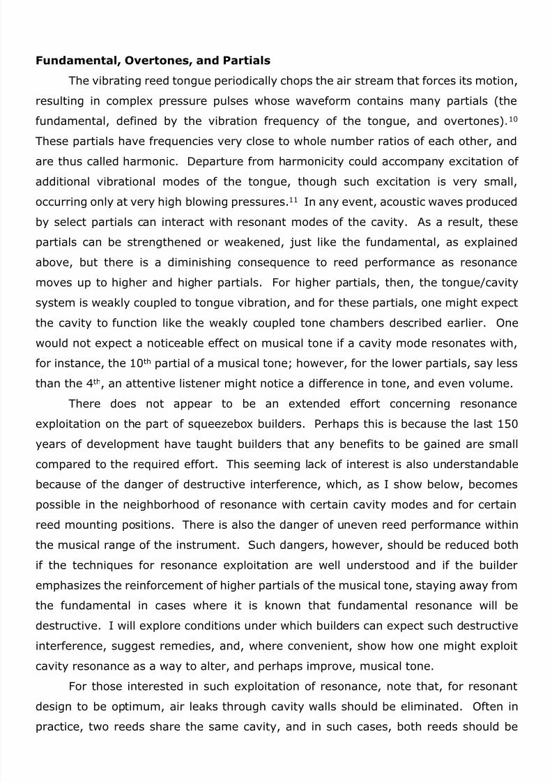
Full-Wave Tube Resonator
A full-wave tube resonator is a tube of length one wavelength, with either both ends
open or both ends closed. Because of the end conditions, such geometry does not
normally exist in squeezebox construction; however, from a theoretical point of view,
and for those interested in how such geometry might be exploited for its resonance
possibilities, Figure 5 illustrates one way in which this could be done. The configuration
here incorporates the open-end conditions. Note the partition in Figure 5, which
creates a tube of one wavelength from a cavity whose length is closer to one-half
wavelength. Note also the placement of the free tip of the reed tongue, which is near
the air hole, at the top. With this arrangement, the requirement for maximum air
velocity by both tongue and cavity air vibrations is satisfied, and amplification should
theoretically occur for the design partial, as well as for partials having frequencies that
are whole number multiples of the frequency of the design partial.19
Fig. 5. Full-Wave Model with Partition.
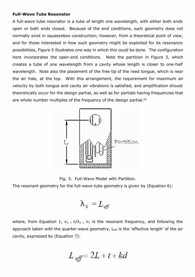
The resonant geometry for the full-wave tube geometry is given by (Equation 6):
where, from Equation 1, o = o , o is the resonant frequency, and following the
approach taken with the quarter-wave geometry, Leff is the ‘effective length’ of the air
cavity, expressed by (Equation 7):

8/6/2019 Reed Cavity Design Resonance
http://slidepdf.com/reader/full/reed-cavity-design-resonance 14/22
where L is the cavity length, t is the thickness of the Action Board, d is aperture di-
ameter, and as in the Helmholtz model above, k is a number from between about 0.4
and 0.8, depending on how close the pallet remains to the aperture. For accuracy,
the restrictions noted in reference to the quarter-wave geometry also apply here.20
As can be seen in Figures 4 and 5, there is a small difference between the
partition in a quarter-wave cavity and that of a full-wave cavity. Provided the reed tips
are mounted as shown, it is a simple matter to physically change a quarter-wave cavity
to a full-wave cavity, though the full-wave cavity must be excited at a frequency four
times that of the quarter-wave cavity.
In looking at the Helmholtz, quarter-wave, and full-wave geometries depicted in
Figures 1, 2, and 5, one might ask: what’s the difference? The difference is the
o, which corresponds to the frequency of the partial
contained in the pressure waveform produced by the vibrating tongue that is being
investigated. In general, the same geometry can behave like a Helmholtz resonator at
one wavelength, like a quarter-wave resonator at another, and like a full-wave
resonator at still another, provided the quarter-wave tube has one end open and the
other closed, and the full-wave tube has both ends open.
Complications
The resonant geometries and corresponding equations for resonant frequency
and resonant cavity lengths for the Helmholtz, quarter-wave, and full-wave geometries
are only models, and inaccuracies can be expected with comparison to the real world.
Some sources of inaccuracy have been pointed out, especially those associated with an
estimate of the effective mass (value for k), the assumed comparative sizes among
cavity dimensions, and the comparison of these dimensions with the wavelength of
oscillation. In practice, such limitations are usually stretched to the limit, and oftenbeyond, in order to utilize such expressions as experimental guidelines. With the
quarter-wave and full-wave models, we should also mention that air motion through
the reed vent (slot) is not entirely concentrated at the end of the cavity; the vibrating
tongue moves through the vent with finite clearance, causing some leakage of acoustic
energy from the cavity. In addition, the presence of reed parts inside the tube causes
changes in cross section that can influence the resonant frequency. Calculations
performed according to suggestions here can be effective illustrators of concepts
involved, but should, because of inaccuracies, be considered only as starting points for
experimentation.

8/6/2019 Reed Cavity Design Resonance
http://slidepdf.com/reader/full/reed-cavity-design-resonance 15/22
Notes:All lengths in inchesNote is nomenclature for piano keyboardPartial is partial number
is frequency of corresponding partial (hz)is wavelength of corresponding partial
Vadj is volume adjustment to orthogonal cavity structure, Equation 3 (cubic inches)W is orthogonal cavity width in Helmholtz modelL is orthogonal cavity length in Helmholtz modeld is aperture diametert is aperture length (Action Board thickness)H is calculated orthogonal cavity height for Helmholtz resonance, Equation 2 & 3, k = 0.6S maxH fixed is cavity height used for tube calculations in next two columnsL-QW is length of cavity for quarter-wave model, Equations 4 & 5, k = 0.6L/2-FW is length of cavity for partitioned full-wave model, Equations 6 & 7, k = 0.6BOLD numbers indicate regions on the musical scale where resonance occurs and/or wherereed choking may occur (when Partial = 1)

8/6/2019 Reed Cavity Design Resonance
http://slidepdf.com/reader/full/reed-cavity-design-resonance 16/22
Sample Calculations
Table 1 presents the results of calculations that illustrate how close reasonable
cavity dimensions come to resonant geometries. One can study Table 1 and draw
conclusions on where along the musical pitch range there is greater or lesser tendency
for cavity resonance to approach the frequencies of various partials of the musical tone.
Table 1 also gives an idea of how much cavity geometries need to be adjusted in order
to arrive at geometries that will resonate at the frequencies of various partials of the
musical tone.
In Table 1, Column Note shows the musical note, with nomenclature based on
the 88-key piano. As can be seen, the calculations represent the musical range of bass
(G1 to C5), baritone (G2 to C6), treble (G3 to C7), and piccolo (G4 to C8) concertinas.
Column Partial shows the partial number of the pressure waveform produced by the
tongue vibration, with fundamental taken as 1, first overtone as 2, etc. Column o
gives the frequency corresponding to the overtone, and Column Vadj gives an
approximate volume adjustment, accounting for departures from the orthogonal
volume calculation (Equation 3). Column o gives the wavelength corresponding to
o, and Columns W, L, d, t, H, and Smax are used in the Helmholtz resonator
calculation, listing (orthogonal) cavity width (W), length (L), height (H), and aperture
diameter (d). Using Equations 2 and 3, we may calculate the value of (H) from theother parameters (W, L, d, and t), whose values were adjusted until a reasonable value
for (H) was obtained. Column S max calculates the maximum size that any of the
previous five parameters can assume, without the simple Helmholtz calculation
becoming inaccurate, as discussed in the previous section on Helmholtz Resonators.
Column H fixed gives the cavity height used in the tube calculations in the next two
columns. Column L-QW gives the cavity length for quarter-wave tube resonance
(Equations 4 and 5), and Column L-FW gives the cavity length of a full-wave resonant
tube (Equations 6 and 7).
As an example, consider the first line in the calculation for note G1; this shows
that the Helmholtz calculation using the fundamental as the design frequency yields a
very large value for cavity height, H (166 inches!), when reasonable values for W, L, d,
and t were chosen. Note that with this calculation, the magnitude of H is much larger
than the value for S max, indicating that the Helmholtz model does not apply;
however, we can still conclude—and the unduly large value for H indicates—that the
resonant Helmholtz geometry is very different from the cavity geometry that would
exist in the real world (which would have a value for H around 0.5 inches). Thus there

8/6/2019 Reed Cavity Design Resonance
http://slidepdf.com/reader/full/reed-cavity-design-resonance 17/22
is no chance that a cavity for this reed pitch could resonate with the fundamental of the
musical tone. The second calculation for note G1 uses the ninth partial (eighth
overtone) as the design frequency, and a smaller value for H is obtained, though still
perhaps not practical (1.11 inches). The third calculation, for the 11th partial, does
show a realistic value for H, assuming moderate adjustments to other cavity
dimensions. Bold numbers here and elsewhere in Table 1 indicate areas of susceptible
resonance matching between cavity modes and various musical tone partials. Thus,
one might conclude on theoretical grounds that some partial higher than about 11 for
this reed pitch may be altered by Helmholtz resonance of the cavity, though it is
doubtful that alteration of such a high overtone would be noticeable to a listener.
Similar comments apply to the fourth line, which calculates the results for an even
higher overtone. Note, however, that the value forS max in this last calculation is less
than the value for L, which indicates that the Helmholtz model is becoming less
accurate.
For note G2, one concludes similarly that there is no chance that a concertina will
be built wherein the cavity provides Helmholtz resonance for the fundamental at reed
pitch G2. As with G1, however, the possibility for such resonance increases as we
consider higher partials, and in particular, one can expect that some partial starting
with the 6th or 7th might experience such resonance.
Thus, higher pitched reeds have cavities that display tendencies to resonate with
decreasing ‘partial number’. For note G3, we find that 4th or 5th partials and higher give
realistic values for H, and thus a possibility to encounter Helmholtz resonance in a
range of overtones that could become noticeable. For note G4, we find that 3rd partials
and higher are candidates for resonance. For these notes, my own experimentation
suggests that the affected partials may experience reinforcement (interference) if the
Helmholtz frequency is a little above (or below) the partial frequency. Note C5produces a 3rd partial as a candidate for Helmholtz resonance, though the pertinent
wavelength is becoming a bit small and the accuracy of this calculation is becoming
compromised (see value for S max). When we get to notes between C5 and C7 and
upward, we see a possibility that the fundamental itself may experience Helmholtz
resonance with the cavity. With notes higher than about C7, wavelengths are becoming
so small that the Helmholtz model may contain serious errors, as shown by
comparative values of S max. Such errors, however, do not mean that the cavity will
not resonate, but only that another model must be applied, and we retain the bold

8/6/2019 Reed Cavity Design Resonance
http://slidepdf.com/reader/full/reed-cavity-design-resonance 18/22
format to indicate the possibility of some sort of resonance with the fundamental.21 In
some of these cases, the tube models become applicable, as discussed below.
I mentioned earlier my own experimental results that suggest interference when
Helmholtz resonance is about equal to or a little lower than reed-tongue vibration
frequency (the fundamental). Table 1 shows that such interference can be expected
somewhere between notes C5 and C6. In theory, a simple fix for compromised reed
performance would be to alter some key cavity or aperture dimension, according to the
resonance formulas presented in this article. For resonance with higher partials, as
with notes G3 to G8, my experimentation has shown that serious interference with the
self- excitation mechanism appears unlikely, though some weakening of tone is
possible when the Helmholtz frequency is close to, or somewhat lower than, the second
or third partial frequency. For Helmholtz resonance at frequencies in a moderate range
that is a little larger than these partial frequencies, I have observed possible
enhancement, suggesting passive filtration by the cavity resonance, as explained in the
sections Fundamental, Overtones and Partials. Should a builder choose to exploit any
possible enhancement at resonance, Table 1 suggests that notes above approximately
G4 would be likely candidates, and that precisely tuned Helmholtz resonators must be
especially made for notes C6 and above, because of the danger of interference leading
to choking.
We now examine the results associated with quarter-wave tube resonance.
Column L-QW was calculated using Equations 4 and 5, and with the realistic values in
Columns W, L, d, t, and H fixed. The idea here is to compare the numbers in Col-
umn L with the numbers in Column L-QW, and quarter-wave resonance is expected
for those partials where these numbers are in reasonable agreement. Bold numbers
again indicate possible resonance areas. As in the case of the Helmholtz calculation,
there is a general trend, with resonance possibilities occurring for lower partial num-bers as the musical pitch increases. Thus, the fifteenth partial of note G1, the fourth
partial of note G4, the third partial of note C5, the second partial of note C6, and the
first partials (fundamentals) of notes C7 and C8 show such behavior. In some of
these calculations, there is departure from the restrictions placed on Equations 4 and
5, though the trends illustrated here should be still valid.
In general terms, we thus come to a similar conclusion as with the Helmholtz
calculation; namely, that the lower-pitched reeds can provide higher partials with
frequencies that can match the quarter-wave resonant mode of their cavities, and that,

8/6/2019 Reed Cavity Design Resonance
http://slidepdf.com/reader/full/reed-cavity-design-resonance 19/22
as the pitch of the reed increases, lower-numbered partials can provide such
frequencies, until we arrive at the highest-pitched reeds, where the fundamental itself
provides such frequencies.
As mentioned earlier, and as shown in Figure 2, concertina cavity designs often
situate the free tip of the reed tongue away from the air hole. From Table 1, for notes
in the octave about C7, this arrangement invites the possibility of reed choking. As also
noted previously, a simple remedy, among others, might be to mount the reed tip at
the aperture end of the cavity, which might then result in tone enhancement. (See the
section Quarter-Wave Tube Resonator for further explanation of such effects.)
Column L-FW does not normally apply to existing concertinas, since its
calculation assumes a partition, with reed orientation shown as in Figure 5. I include
it for completeness, and it may be of import to those interested in understanding and
exploiting resonance phenomenon. Table 1 shows that only the highest-pitched reeds
are expected to show susceptibility for fundamental resonance with full-wave tubes,
indicating applicability somewhere in the vicinity of note C8.
One can see that the occurrence of resonant behavior in Table 1 is dependent
upon the assumed dimensions of the cavities, and that real concertinas will have other
cavity dimensions and other occurrences. It is important to note, however, that the
general trend concluded here for both Helmholtz and tube models should be valid for
real instruments.
Summary and Conclusions
Reed cavity resonance exhibits a full range of influence on concertina reed
performance. In some cases, reed cavities have very little effect, while in other cases,
there can be significant effect on the timbre and volume of the musical tone. Finally,
resonance effects can cause serious interference with reed tongue vibration andmusical tone, particularly for Helmholtz and quarter-wave resonance with high-pitched
reeds. The Helmholtz resonator and quarter-wave tube models can explain much of
the resonant behavior of reed cavities, and I have presented methods to calculate their
resonant
geometries. The sample calculations illustrate the range of influence of resonance on
bass, baritone, treble, and piccolo instruments. For the lowest range of these
instruments, only the higher partials of the musical tone appear open to influence. As
one moves up the pitch range of this family of instruments, lower-numbered, more
noticeable partials become susceptible to influence from cavity resonance, and for the

8/6/2019 Reed Cavity Design Resonance
http://slidepdf.com/reader/full/reed-cavity-design-resonance 20/22
highest pitches, I suggest resonant interference and reed choking is a danger in some
cavity designs. Helmholtz resonance appears to be the more commonly experienced
type of resonance, though quarter-wave resonance makes a significant appearance, in
a less regular fashion.
In this article, I have presented possible mechanisms for interference and
choking, remedies to prevent such behavior, and suggestions on how one might
attempt exploitation of resonant effects for improved musical tone. These discussions
and suggestions are based, in part, on my limited experimentation on these issues,
which I cannot say is universally conclusive. Free-reed operation is a complicated
affair, and I hope the discussion here can encourage participation by others.
NOTES
1. See for instance, Gerhard Richter: Akustische Probleme bei Akkordeons und Mundharmonikas, Teil 1:
Allgemeine Grundlagen (Kamen, Germany: Karthause-Schmulling, 1985). More recent—and in English—is
a series of papers by James P. Cottingham, abstracts of which are published in The Journal of the Acoustical
Society of America: ‘Acoustics of American Reed Organs’, 99 (1996), 2461; with Casey A. Fetzer, ‘Modeling
Free Reed Behavior using Calculated Reed Admittance’, 102 (1997), 3084; ‘Theoretical and Experimental
Investigation of the Air-Driven Free Reed’, 103 (1998), 2835.
2. Care must be taken so that no air jets or concentrations of air streams interfere with the self-excitationmechanism of tongue vibration.
3. Damping (friction) is also present in any real system, though it is not required for resonance. In this article,
we neglect the small effect damping has on cavity resonant frequencies.
4. There is a mean (time-average) airflow through the cavity, upon which is superimposed an air vibration with
oscillating pressure and velocity. The magnitude of these oscillations depends upon spatial position within
and about the cavity.
5. Any concertina player can observe the tone chamber effect by playing the instrument close inside the corner
of a room. Sound reflection off the walls in this case produces a tone with timbre noticeably different from
that of the tone played out in the open.
6. Free reeds were used in organ pipes, though they were, to my knowledge, discontinued during the 1920’s
because their start (attack) transient was regarded as too slow.
7. See Cottingham, ‘Acoustics of a Symmetric Free Reed Coupled to a Pipe Resonator’, abstract in The
Journal of the Acoustical Society of America, 107 (2000), 2896. An important difference between Asian and
8/6/2019 Reed Cavity Design Resonance
http://slidepdf.com/reader/full/reed-cavity-design-resonance 21/22
Western free reeds is that the Asian reed operates always as an “opening” reed, whereas the Western free reed
operates as a “closing” reed and sometimes as both a “closing” reed and an “opening” reed. For an
explanation of this terminology and the implications, see Neville H. Fletcher and Thomas D. Rossing, The
Physics of Musical Instruments, 2nd ed. (New York: Springer, 1999), 401, 413.
8. Aldo Mencasini, owner, Bell-Duovox Accordion, West Nyack, New York, private communication.
9. The presence of a mean flow through the reed vent has a small (second order), but sometimes significant,
effect on reed performance.
10. Some people are erroneously under the impression that the partials in the musical tone of squeezeboxes
are caused by higher resonance modes in the reed tongue itself, in the same way that a vibrating guitar string
produces its partials.
11. See Cottingham, C. Joseph Lilly, and Christopher H. Reed, ‘The Motion of Air-Driven Free Reeds’, The
Journal of the Acoustical Society of America, 105 (1999), 940.
12. By partition, I mean a lengthwise divider down the middle of the cavity, with only the vicinity of the port
hole allowing acoustical communication between the resulting half-size cavities.
13. Named after Hermann Helmholtz (1821-1894), whose Die Lehre von den Tonempfindungen als physiolo-
gische Grundlage für die Theorie der Musik (Brunswick, 1863; English translation by A. J. Ellis,
1875/reprinted 1956, as On the Sensations of Tone) is one of the classic studies of musical acoustics. As Allan
W. Atlas has noted, Ellis himself played the concertina; see ‘Who Bought Concertinas in the Winter of 1851?
A Glimpse at the Sales Accounts of Wheatstone & Co.’, Nineteenth-Century British Music Studies, 1, ed.
Bennett Zon (Aldershot: Ashgate, 1999), 63-64.
14. The calculation of k is a complex exercise, though it has been done for cases that approximate its
application here. The “end correction” kd is necessary to account for the inertia of the air mass that
vibrates in the region immediately outside the air hole, and the extent of this mass depends upon the
size of the hole with respect to the wavelength and the proximity of the pallet to the hole. For
instruments where the pallet remains closer to the hole than stated, even larger values of k should be
used. Such an effect is used in some marimbas, as a way of tuning the associated quarter-wave tube
resonator. Note also that radiation loss from the cavity should be small when the stated restrictions are
satisfied and is thus neglected in these calculations.
15. The main reason for this requirement is to ensure that the inherent assumptions of one- dimensionalflow inside the tube are adhered to. For more rigorous conformity between this quarter-wave model and
practice, one can place partitions down the center of the cavity, effectively doubling the ratio L/W, as
discussed elsewhere in the text.

8/6/2019 Reed Cavity Design Resonance
http://slidepdf.com/reader/full/reed-cavity-design-resonance 22/22
Since the transverse dimensions are assumed much less than a quarter wavelength, waveform
variations in the transverse direction are negligible, and the cross-sectional shape of the tube is not
important, unless higher-order effects, such as wall friction, are included.
16. Since the clarinet is basically a quarter-wave tube with one end open and the other closed, and with
the reed placed at the closed end, one might ask why the free reed behaves differently. The answer lies
in the nature of the two reeds, as explained previously. The clarinet reed is a pressure-controlling device,
whereas the free reed is a flow-controlling device. With the tube in resonance, the boundary condition
at the wall requires a velocity node and a pressure maximum. Such a condition is compatible with the
clarinet’s beating reed and incompatible with the free reed.
17. See also note 14
18. The appearance of transverse standing waves should not invalidate the expressions given here; they
can only add additional modes of vibration. Because of the geometries involved and the wall (zero
velocity) boundary conditions in the transverse direction, only those transverse modes that support
partials with frequencies having whole number ratios of the pertinent frequency are likely, and these
would most often result in frequencies too high to be of interest. The resonant frequencies of mixed
longitudinal/transverse modes, however, require a more complicated analysis.
19. One might be curious about why we skipped half-wave tube resonators, which would be shorter and
perhaps more practical than full-wave tubes. The reason is that half-wave tubes require both ends open,
and oscillations at one end are 180 degrees out of phase with those at the other end. Thus anarrangement with the vibrating reed tip at both ends, as in Figure 5, could not work, since this
arrangement excites the two ends of the tube air with the same phase. Of course, one might separate
both ends of the (half-wave and full-wave) tubes and excite only one end, but this would require two
pallets connected to the same key, and this arrangement is not considered practical.
20. When the aperture area becomes too small in comparison to the tube cross section, WH, the end
conditions are no longer simply ‘open’, but in this case, the tube may still function as a full-wave
resonator, since even ‘closed’ conditions allow resonance (see also note 14).
21. For those interested in calculating the ‘Helmholtz’ resonant frequency in these cases, see Fletcher
and Rossing, The Physics of Musical Instruments, 227–32, where a discussion is given for cases in
which resonator dimensions are comparable to the wavelength in the long direction, L, but still require
the transverse dimensions, W and H, to be much less than the wavelength. With these more complicat-
ed calculations involving wavelength effects, in which the resonator ceases to behave as the simple
resonator, overtones occur, introducing additional possibilities for resonance.