Embed Size (px)
Citation preview
8/17/2019 REED Switch charactheristic..pdf
http://slidepdf.com/reader/full/reed-switch-charactheristicpdf 1/2
www.gems-sensors.co.uk
INTRODUCTION
5
What is a reed switch?OperationAll GEMS switches work on a combined reed switch/permanent magnet basis.
What is a reed switch?
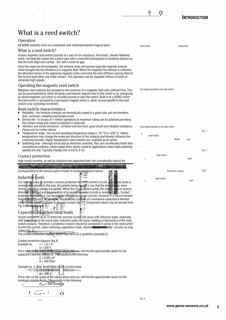
A basic magnetic reed switch consists of a pair of low resistance, ferromatic, slender flattenedreeds, hermetically sealed into a glass tube with a controlled atmosphere in cantilever fashion sothat the ends align and overlap - but with a small air gap.
Since the reeds are ferromagnetic, the extreme ends will assume opposite magnetic polaritywhen brought into the influence of a magnetic field. When the magnetic flux density is sufficient,the attraction forces of the opposing magnetic poles overcome the reed stiffness causing them toflex toward each other and make contact. This operation can be repeated millions of times atextremely high speeds.
Operating the magnetic reed switchMagnetic reed switches are actuated by the presence of a magnetic field with sufficient flux. Thiscan be accomplished by either bringing a permanent magnet close to the switch or by energizingan electromagnetic coil which is mounted around or near the switch. Built-in to a GEMS switchthe reed switch is actuated by a permanent magnet which is either moved parallel to the reedswitch or by a pivoting movement.
Reed switch characteristics Reliability - the rhodium contacts are hermetically sealed in a glass tube and are therefore,
dust, corrosion, oxidation and tamper proof. Service life - in excess of 1 million operations at maximum rating can be achieved providing
the contact rating and contact protection is observed. Vibration and shock resistance - all these switches have good shock and vibration resistance.
Please ask for further details. Temperature range - the normal operating temperature range is -20 °C to +250 °C. Higher
temperatures may change the molecular structure of the contacts and thereby influence theswitching function. Higher temperature reed switches are available as an option.
Switching time - although not as fast as electronic switches, they are considerably faster thanconventional switches, which makes them ideally suited to applications where high switchingspeeds are vital. Typically change over is 0.6 to 2 ms.
~
Contact protectionHigh inrush currents, as well as inductive and capacitive load, can considerably reduce theservice life of a reed switch and under extreme circumstances result in a destruction of the
contacts. Therefore, the following guidelines are to help the user to install protection circuitscorresponding to the various types of loads to avoid a premature failure.
Inductive loadsIt is relatively easy to provide a contact protection for direct current circuits. An inverse diode isconnected in parallel to the load, the polarity being in such a way that the diode blocks whennormal operating voltage is supplied. When the circuit is interrupted, the voltage peak in reversedirection is shorted and the formation of an arc between the circuits is avoided (fig.1). Contactprotection by a diode is not feasable for alternating current circuits. However, it is recommendedthat an arc attenuator be provided, which usually consists of a resistance-capacitance elementwhich is connected in parallel to the reed contact (fig. 2). Component values may be derived fromFig. 4 below (example 1).
Capacitive loads and lamp loadsInrush currents of up to 15 times the nominal current can occur with inductive loads, especiallywith lamp loads. In the worst case, inductive loads can cause welding or destruction of the reed
switch contacts. Therefore, a protection resistor should be connected in series to the reed switchto limit the current, when switching capacitative loads, filament lamps and other circuits via longcables (fig. 3).The contact protection diagram below may serve as a guideline (example 2).
Contact protection diagram (fig.4)Example no. 1: I = 0.1 A
U = 220 VPut a ruler on the graph at the values above and you will find the approximate values for thecapacitor C and the resistor R. This results in the following:
C = 0.001 µFR = 340 Ohm
Example no. 2: max. permissible inrush current pulse:I = 0.5 AU = 200 V
Put a ruler on the graph at the values above and you will find the approximate values for the
minimum resistor R min. This results in the following:Rmin = 400 Ohm
Fig. 4
load
reed switch
+
-
loaddiode
reed switch
Fig. 1
Fig. 2
~
reed switch contact lips
bar magnet parallel to the reed switch
ring magnet parallel to the reed switch
Protection resistor
reed switchload
Fig.3
8/17/2019 REED Switch charactheristic..pdf
http://slidepdf.com/reader/full/reed-switch-charactheristicpdf 2/2
6
Acceptance and ApprovalsVarious Civil, Military, Naval and Coast Guard approvals have been attained for special products. Some switches have been developed for applications in shipsand have passed shock and vibration tests, seismic shock tests and other quality tests. Please ask for further details.
www.gems-sensors.co.uk
All GEMS level switches operate according to the schematic drawings.
A float equipped with one or more magnets moves up and down with the fluid level and actuateswith its magnetic field a hermetically sealed reed switch embedded in the stem.
The switches can be provided as normally open normally closed or change-over contacts.
The advantage of this principle:
There is only one moving part - the float. This actuates the reed switch with its magnetic fieldwithout causing any wear. The reed switch itself is totally isolated from the media.
These advantages give the user safe, repeatable, accurate and high operational reliability with lowmaintenance over a long and trouble-free life.
Operating Principle of Gems Level Switches
GEMS flow switches work according to the principle which is shown in the simplified diagramson this page.
One can differentiate between two main operating principals:
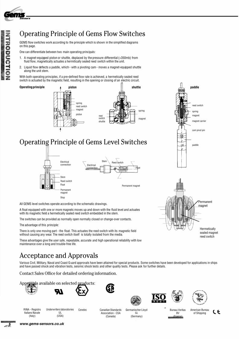
1. A magnet-equipped piston or shuttle, displaced by the pressure differential (>350mb) fromfluid flow, magnetically actuates a hermitically sealed reed switch within the unit.
2. Liquid flow deflects a paddle, which - with a pivoting cam - moves a magnet-equipped shuttlealong the unit stem.
With both operating principles, if a pre-defined flow rate is achieved, a hermetically sealed reedswitch is actuated by the magnetic field, resulting in the opening or closing of an electric circuit.
Operating Principle of Gems Flow Switches
Approvals available on selected products:
paddleOperating principle
reed switch
spring
magnet
magnet carrier
cam pivot pin
paddle
spring
reed switch
magnet
piston
piston
spring
magnet
reed
switchshuttle
shuttle
RINA - RegistroItaliano Navale
(Italy)
Underwriters laboratoriesUL
(USA)
Canadian StandardsAssociation - CSA
(Canada)
Cenelec Germanischer LloydGL
(Germany)
Electricalconnection
StemReed switch
Float
Permanentmagnet
Stop
Electricalconnection
StemReed switch
Float
Permanent magnet
Hermeticallysealed magnet
reed switch
Permanentmagnet
Contact Sales Office for detailed ordering information.
Bureau VeritasBV
(France)
American Bureauof Shipping