Embed Size (px)
Citation preview
1
Reef 2000
Operation manual GB
6-stage water treatment system for reef aquaria up to 1500 l.
With the purchase of this filtration system, you have selected a top quality product. It has been
specifically designed for aquaristic purposes and has been tested by professionals.
With this unit - if used correctly - you are able to reduce organic substances and other pollutants of
your aquarium water to non-toxic levels.
The filtration system consists of two mechanical pre-filters, a motor driven protein skimmer with
post-switched trickling filters, an anaerobic denitrifying filter, a Calcium reactor and an automatic
water refilling device.
The filtration system Reef 2000 convinces by its compact and functional design and its clear arrangement.
GmbH
Gewerbepark 24, 49143 Bissendorf, Germany
__________________________________________________________________________________________
2
1. Product description
The outside filtration system Reef 2000 is placed in a separate glass tank. The skimmer Turboflotor 5000 Shorty Compact and both return pumps are placed next to the glass tank.
The dimensions over all are 155 x 45 x 62 cm ( L x W x H).
The system consists of the following components:
1. Glass tank, the dimensions are: 90 x 45 x 40 cm (L x W x H). 2. Protein skimmer Turboflotor 5000 Shorty Compact with post-switched mechanical filter
(sponge) and biological wet/dry trickle filter, filled with Bactoballs. 3. Second mechanic pre-filter sponge with smaller post-switched wet/dry trickle filter, filled with
Bactoballs. 4. Nitratereductor NR 1000 with integrated circulation pump. 5. Calciumreactor KR 1000 with integrated circulation pump. 6. 2 pcs. circulation pump Ocean Runner OR 3500. 7. Refill pump SP 3000, with level sensor. 8. Top-up tank with hose connection for completing evaporated water. 2. General description of the system The water flows out of the aquarium via overflow chamber or another overflow device (e. g. an AB
Aqua Medic Overflow Box) into the filter. The water flow is divided at a T-piece. One part is directed to the Turboflotor Shorty Compact, the rest flows directly through a mechanic sponge filter
to the wet/dry biological filter. The water flow between skimmer and biofilter can be adjusted with
2 ball valves. From the protein skimmer, the water flows to a second smaller but similar built unit
of mechanic filter and wet/dry biofilter. From the biofilters, the water flows into the filter sump.
The Nitratereductor and Calciumreactor are supplied with water via a bypass. This water is taken from the pressure tube which pumps the purified water upwards back to the tank. To
fasciliate the water supply for these filters, a dosing pump (SP 3000) may be used.
The top-up tank with re-fill water is placed inside the filter sump on a plastic base. The refill
(peristaltic pump SP 3000) is supplied with a level sensor. It should be placed above the storage
tank. The level sensor is fixed in the tank of the filter and marks the optimum water level in the
filter sump.
During installation of the pumps and plumbing, it has to be ensured that no resonance bodies are
created because these may cause - depending on the type of pumps used - nasty noises.
3
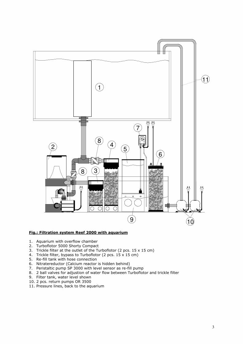
Fig.: Filtration system Reef 2000 with aquarium 1. Aquarium with overflow chamber
2. Turboflotor 5000 Shorty Compact
3. Trickle filter at the outlet of the Turboflotor (2 pcs. 15 x 15 cm)
4. Trickle filter, bypass to Turboflotor (2 pcs. 15 x 15 cm)
5. Re-fill tank with hose connection
6. Nitratereductor (Calcium reactor is hidden behind)
7. Peristaltic pump SP 3000 with level sensor as re-fill pump
8. 2 ball valves for adjustion of water flow between Turboflotor and trickle filter
9. Filter tank, water level shown
10. 2 pcs. return pumps OR 3500
11. Pressure lines, back to the aquarium
1
8
8
5
7
2
3
9
6
10
4
11
4
3. Set-up of the filter The outside filtration system Reef 2000 is supplied in a ready-to-use-condition in a glass tank. This tank has the dimensions 90 x 45 x 40 cm .
It can be placed in the cabinet of all standard aquaria. Because it is an open system, it should be
taken care that the cabinet is a water-proof system.
Inflow to the filter:
The plumbing from aquarium to the filter should be performed with a PVC-pipe or a flexible tube of
50 mm (2”) diameter. The connection to the filter system is a screw connection for 50 mm pipes
(included). At this position, the system can easily be disconnected.
It may be useful to install a ball valve between tank and filter to avoid following water drops during
the disconnection.
Suction pipe of the pump: The pumps should be placed aside the filter tank. The suction pipe for the pump is performed with
a PVC pipe of 32 mm (1.25 inch). Also here, it is useful to install a ball valve between filter tank
and pump because the pump can easier be removed for maintenance purposes.
Pressure pipe:
The pressure pipes of both pumps are performed - according to their capacity- with a flexible tube
or with a PVC pipe of 25 mm diameter. In each case, a junction in one pessure pipe has to be
performed to supply the Calciumreactor and Nitratereductor with water. It is advisable to perform at least one part of the pressure pipe with a flexible tube (PVC silicone) to avoid
vibrations. This eliminates the transfer of vibrations from pump to aquarium and consequential
noises.
Circulation pump:
The filter system is equipped with 2 pump suction openings for 2 circulation pumps, model Ocean
Runner 3500. The use of 2 pumps ensures the operation of the system in case of a failure of one
pump. Of course, also the filter can be pursued with a pump. This should have a capacity of 3,500
l/h minimum. Otherwise, the Turboflotor will not work perfectly.
4. Water reservoir - Water level in the filter tank All open filter systems have to be planned in a way that in case of a circulation pump failure they
can take up water flowing back from the aquarium without creating an overflow. The volume of
water is depending on the construction of the overflow device, pump capacity, circulation pump
and aquarium surface. The water volume can be calculated by taking the aquarium surface (length
x width) and the build-up above the overflow level resp. overflow comb. In most cases, the build-
up is 2 - 3 cm.
During normal operation, the filter tank can only be filled to a height that this water volume is
taken up in case of emergency. The minimum water level is determined through the height of the
pump suction opening. It has to be made sure that the pump does not suck any air. Otherwise, fine
air bubbles are blown into the water which create a lot of slurp noises. If the pump runs dry, it may
get damaged irreversibly. The water which evaporates within the aquarium, is only missed in the
filter chamber - in the aquarium itself, the water level will be maintained. For this reason, the
water level has be controlled and replenished regularly. The re-filling can be made easier by using
the automatic top up system (peristaltic pump SP 3000 with level sensor and re-fill tank) in order
to keep the water level constant. Nevertheless, it is suitable to mark minimum and maximum
levels directly at the tank.
We recommend to use only pre-treated tap water (reverse osmosis) for re-filling.
5
Large aquaria - equilibration tank:
If the reserve volume of the filter tank is not sufficient with large aquaria to take up water during a
pump failure, an equilibrium tank has to be added. Possibly, you can get an appropriate tank from
your local aquarium manufacturer. This tank has to be fixed at the filter tank with a pipe
connection. The circulation pump sucks water from the equilibration tank and pumps it into the
aquarium.
5. Automatic top-up system The Reef 2000 is supplied with an automatic top-up system. The storage tank (5) is filled with pre-
treated tap water (reverse osmose). The tank can be re-filled during operation without opening the
lid. At the right side, there is a hole for the included bulkhead fitting and hose connector. The water
can be filled by a hose and help of a pump or from a bucket.
The level sensor that is connected to the peristaltic pump is fixed in the filter tank with the rubber
succers. The height where it is fixed depends on the aquarium (see item 4 water level). The sensor
has to be fixed as low as possible, but minimum in a height that the pumps do not suck in air or
run dry, and maximum in a height that the filter tank can take water flowing back from the
aquarium when the pumps are shut off.
To prevent any accidents, the rubber succers of the level sensors can be glued to the filter tank
with a drop of silicone – once the optimum position has been determined.
6. Installation of the filter
When the plumbing is finished and all joins are dry, the system is ready to use. The following
points should be checked:
- Are all unions tight? Maybe, they have to be tightened. Check for leaks.
- Is the water distribution between trickle filter and Turboflotor ok, so the skimmer operates perfectly.
- The pumps at the Calciumreactor and the Nitratereductor must be filled completely with water before they are taken into operation.
7. Warranty
Should any defect in material or workmanship be found within twelve months of the date of
purchase AB Aqua Medic GmbH undertakes to repair or, at our option, replace the defective part
free of charge – always provided the product has been installed correctly, is used for the purpose
that was intended by us, is used in accordance with the operating instructions and is returned to us
carriage paid. The warranty term is not applicable on the all consumable products.
Proof of Purchase is required by presentation of an original invoice or receipt indicating the dealer’s
name, the model number and date of purchase, or a Guarantee Card if appropriate. This warranty
may not apply if any model or production number has been altered, deleted or removed,
unauthorised persons or organisations have executed repairs, modifications or alterations, or
damage is caused by accident, misuse or neglect.
We regret we are unable to accept any liability for any consequential loss.
Please note that the product is not defective under the terms of this warranty where the product,
or any of its component parts, was not originally designed and / or manufactured for the market in
which it is used.
These statements do not affect your statutory rights as a customer.
If your AB Aqua Medic GmbH product does not appear to be working correctly or appears to be
defective please contact your dealer in the first instance.
Before calling your dealer please ensure you have read and understood the operating instructions.
If you have any questions your dealer cannot answer please contact us.
Our policy is one of continual technical improvement and we reserve the right to modify and adjust
the specification of our products without prior notification.
AB AQUA MEDIC GmbH - Gewerbepark 24 - 49143 Bissendorf/Germany - Technical changes reserved – 08/2010
6
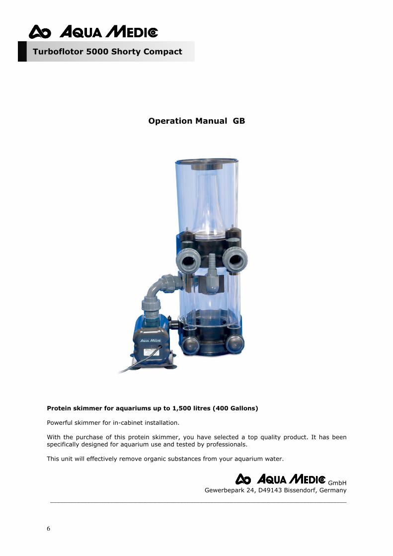
Turboflotor 5000 Shorty Compact
Operation Manual GB
Protein skimmer for aquariums up to 1,500 litres (400 Gallons)
Powerful skimmer for in-cabinet installation.
With the purchase of this protein skimmer, you have selected a top quality product. It has been
specifically designed for aquarium use and tested by professionals.
This unit will effectively remove organic substances from your aquarium water.
GmbH
Gewerbepark 24, D49143 Bissendorf, Germany
_________________________________________________________________________________________
7
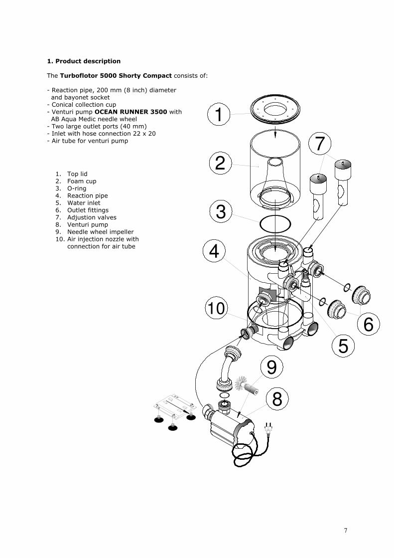
1. Product description
The Turboflotor 5000 Shorty Compact consists of:
- Reaction pipe, 200 mm (8 inch) diameter
and bayonet socket
- Conical collection cup
- Venturi pump OCEAN RUNNER 3500 with AB Aqua Medic needle wheel
- Two large outlet ports (40 mm)
- Inlet with hose connection 22 x 20
- Air tube for venturi pump
1. Top lid
2. Foam cup
3. O-ring
4. Reaction pipe
5. Water inlet
6. Outlet fittings
7. Adjustion valves
8. Venturi pump
9. Needle wheel impeller
10. Air injection nozzle with
connection for air tube
3
2
1
6
4
5
7
10
8
9
8
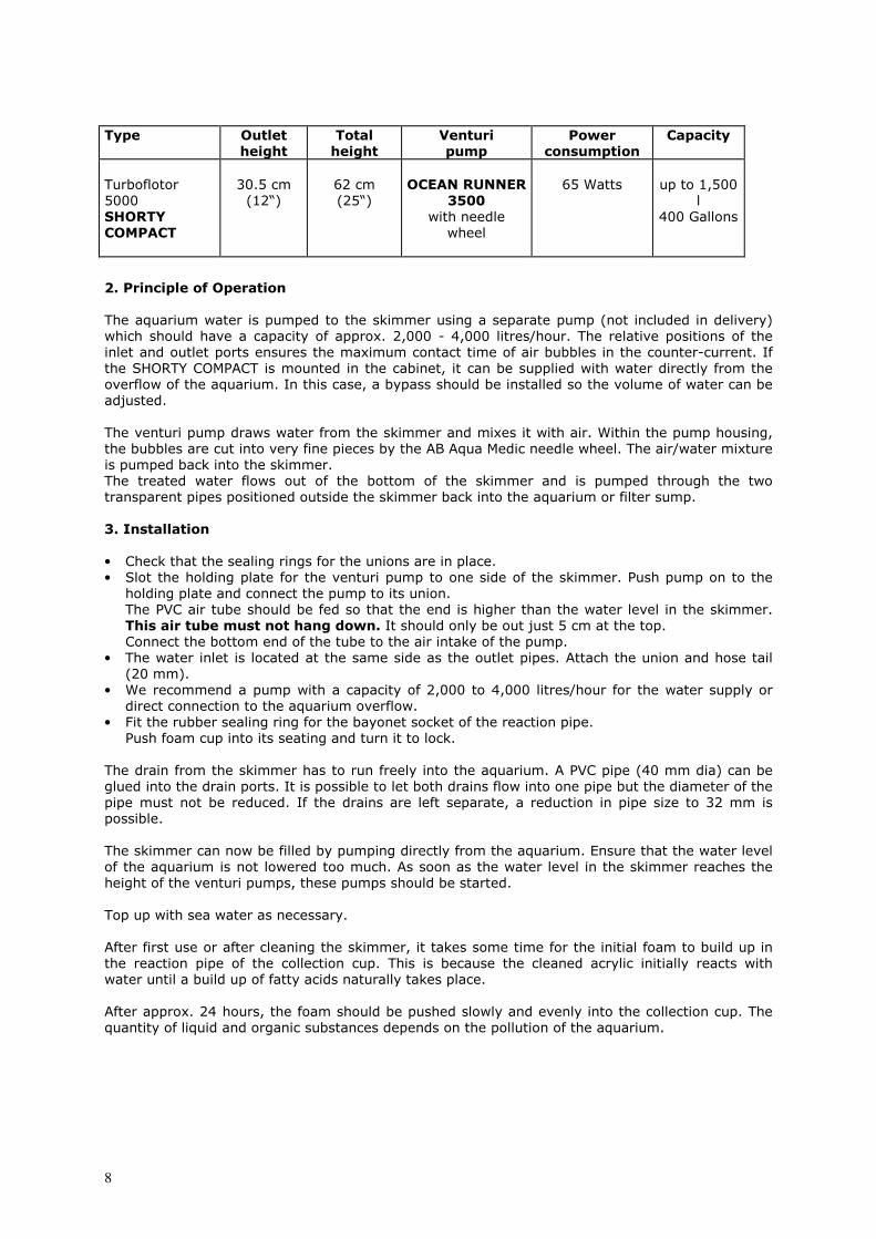
Type Outlet height
Total height
Venturi pump
Power consumption
Capacity
Turboflotor
5000
SHORTY COMPACT
30.5 cm
(12“)
62 cm
(25“)
OCEAN RUNNER 3500
with needle
wheel
65 Watts
up to 1,500
l
400 Gallons
2. Principle of Operation
The aquarium water is pumped to the skimmer using a separate pump (not included in delivery)
which should have a capacity of approx. 2,000 - 4,000 litres/hour. The relative positions of the
inlet and outlet ports ensures the maximum contact time of air bubbles in the counter-current. If
the SHORTY COMPACT is mounted in the cabinet, it can be supplied with water directly from the
overflow of the aquarium. In this case, a bypass should be installed so the volume of water can be
adjusted.
The venturi pump draws water from the skimmer and mixes it with air. Within the pump housing,
the bubbles are cut into very fine pieces by the AB Aqua Medic needle wheel. The air/water mixture
is pumped back into the skimmer.
The treated water flows out of the bottom of the skimmer and is pumped through the two
transparent pipes positioned outside the skimmer back into the aquarium or filter sump.
3. Installation
• Check that the sealing rings for the unions are in place.
• Slot the holding plate for the venturi pump to one side of the skimmer. Push pump on to the
holding plate and connect the pump to its union.
The PVC air tube should be fed so that the end is higher than the water level in the skimmer.
This air tube must not hang down. It should only be out just 5 cm at the top. Connect the bottom end of the tube to the air intake of the pump.
• The water inlet is located at the same side as the outlet pipes. Attach the union and hose tail
(20 mm).
• We recommend a pump with a capacity of 2,000 to 4,000 litres/hour for the water supply or
direct connection to the aquarium overflow.
• Fit the rubber sealing ring for the bayonet socket of the reaction pipe.
Push foam cup into its seating and turn it to lock.
The drain from the skimmer has to run freely into the aquarium. A PVC pipe (40 mm dia) can be
glued into the drain ports. It is possible to let both drains flow into one pipe but the diameter of the
pipe must not be reduced. If the drains are left separate, a reduction in pipe size to 32 mm is
possible.
The skimmer can now be filled by pumping directly from the aquarium. Ensure that the water level
of the aquarium is not lowered too much. As soon as the water level in the skimmer reaches the
height of the venturi pumps, these pumps should be started.
Top up with sea water as necessary.
After first use or after cleaning the skimmer, it takes some time for the initial foam to build up in
the reaction pipe of the collection cup. This is because the cleaned acrylic initially reacts with
water until a build up of fatty acids naturally takes place.
After approx. 24 hours, the foam should be pushed slowly and evenly into the collection cup. The
quantity of liquid and organic substances depends on the pollution of the aquarium.
9
4. Maintenance
• Collection cup: Depending on the organic load, the cup should be cleaned daily to weekly. Reaction pipe: This only needs occasional cleaning. We recommend intervals from 6 to 12
months.
• Venturi pump: The maintenance of the pump should be done at the same time as the reaction pipe:
Drain the water out and dismantle the pump. Flush the pump housing and needle wheel with
clean water.
The same should be done with the air injection nozzle. 5. Failures
Failures may arise if:
- the ratio between supplied air and water volume is not correct.
Cause: The air injection nozzle is clogged or the pump chamber containing the needle wheel is dirty.
Action: Dismantle venturi pump, clean it thoroughly, carefully clean the air injection nozzle with a
thin brush or blunt instrument and re-assemble the pump again.
- the venturi pump does not re-start after an interruption of power supply.
Cause: The water pressure is too high.
Action: Let the water out up to the height of the pump to lower the water pressure.
Re-start the pump.
7. Warranty
Should any defect in material or workmanship be found within twelve months of the date of
purchase AB Aqua Medic GmbH undertakes to repair or, at our option, replace the defective part
free of charge – always provided the product has been installed correctly, is used for the purpose
that was intended by us, is used in accordance with the operating instructions and is returned to us
carriage paid. The warranty term is not applicable on the all consumable products.
Proof of Purchase is required by presentation of an original invoice or receipt indicating the dealer’s
name, the model number and date of purchase, or a Guarantee Card if appropriate. This warranty
may not apply if any model or production number has been altered, deleted or removed,
unauthorised persons or organisations have executed repairs, modifications or alterations, or
damage is caused by accident, misuse or neglect.
We regret we are unable to accept any liability for any consequential loss.
Please note that the product is not defective under the terms of this warranty where the product,
or any of its component parts, was not originally designed and / or manufactured for the market in
which it is used.
These statements do not affect your statutory rights as a customer.
If your AB Aqua Medic GmbH product does not appear to be working correctly or appears to be
defective please contact your dealer in the first instance.
Before calling your dealer please ensure you have read and understood the operating instructions.
If you have any questions your dealer cannot answer please contact us.
Our policy is one of continual technical improvement and we reserve the right to modify and adjust
the specification of our products without prior notification.
AB AQUA MEDIC GmbH - Gewerbepark 24 - 49143 Bissendorf/Germany - Technical changes reserved – 04/2010
10
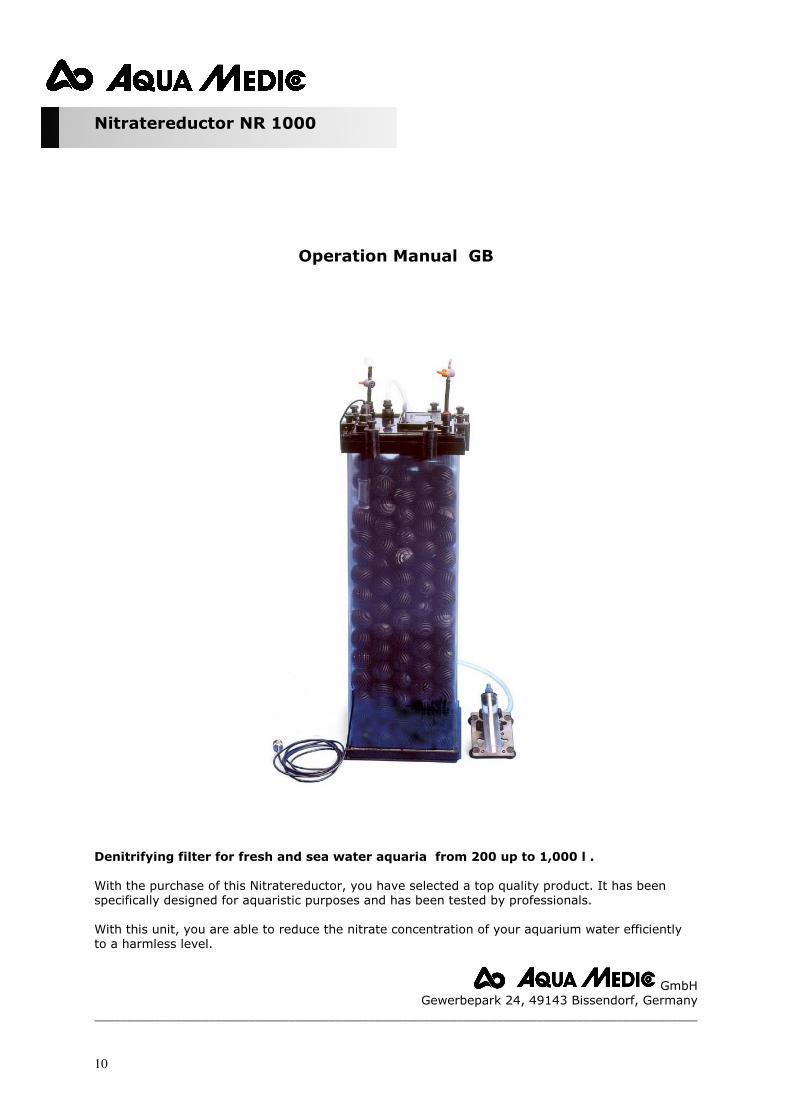
Nitratereductor NR 1000
Operation Manual GB Denitrifying filter for fresh and sea water aquaria from 200 up to 1,000 l . With the purchase of this Nitratereductor, you have selected a top quality product. It has been
specifically designed for aquaristic purposes and has been tested by professionals.
With this unit, you are able to reduce the nitrate concentration of your aquarium water efficiently
to a harmless level.
GmbH
Gewerbepark 24, 49143 Bissendorf, Germany
__________________________________________________________________________________________
11
9
8
7
1110
5
6
34
17
12
13
14
15
16
2
1
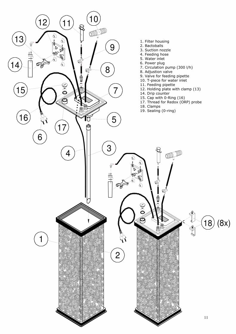
1. Filter housing
2. Bactoballs
3. Suction nozzle
4. Feeding hose
5. Water inlet
6. Power plug
7. Circulation pump (300 l/h)
8. Adjustion valve
9. Valve for feeding pipette
10. T-piece for water inlet
11. Feeding pipette
12. Holding plate with clamp (13)
14. Drip counter
15. Cap with 0-Ring (16)
17. Thread for Redox (ORP) probe
18. Clamps
19. Sealing (0-ring)
(8x)18
12
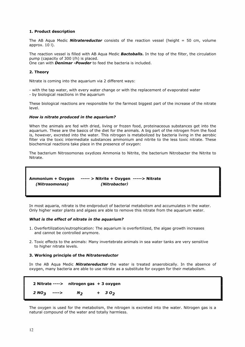
1. Product description
The AB Aqua Medic Nitratereductor consists of the reaction vessel (height = 50 cm, volume
approx. 10 l).
The reaction vessel is filled with AB Aqua Medic Bactoballs. In the top of the filter, the circulation pump (capacity of 300 l/h) is placed.
One can with Denimar -Powder to feed the bacteria is included.
2. Theory Nitrate is coming into the aquarium via 2 different ways:
- with the tap water, with every water change or with the replacement of evaporated water
- by biological reactions in the aquarium
These biological reactions are responsible for the farmost biggest part of the increase of the nitrate
level.
How is nitrate produced in the aquarium?
When the animals are fed with dried, living or frozen food, proteinaceous substances get into the
aquarium. These are the basics of the diet for the animals. A big part of the nitrogen from the food
is, however, excreted into the water. This nitrogen is metabolized by bacteria living in the aerobic
filter via the toxic intermediate substances ammonium and nitrite to the less toxic nitrate. These
biochemical reactions take place in the presence of oxygen:
The bacterium Nitrosomonas oxydizes Ammonia to Nitrite, the bacterium Nitrobacter the Nitrite to
Nitrate.
Ammonium + Oxygen ----- > Nitrite + Oxygen -----> Nitrate
(Nitrosomonas) (Nitrobacter)
In most aquaria, nitrate is the endproduct of bacterial metabolism and accumulates in the water.
Only higher water plants and algaes are able to remove this nitrate from the aquarium water.
What is the effect of nitrate in the aquarium?
1. Overfertilization/eutrophication: The aquarium is overfertilized, the algae growth increases
and cannot be controlled anymore.
2. Toxic effects to the animals: Many invertebrate animals in sea water tanks are very sensitive
to higher nitrate levels.
3. Working principle of the Nitratereductor
In the AB Aqua Medic Nitratereductor the water is treated anaerobically. In the absence of
oxygen, many bacteria are able to use nitrate as a substitute for oxygen for their metabolism.
2 Nitrate ----> nitrogen gas + 3 oxygen 2 NO3 ----> N2 + 3 O2
The oxygen is used for the metabolism, the nitrogen is excreted into the water. Nitrogen gas is a
natural compound of the water and totally harmless.
13
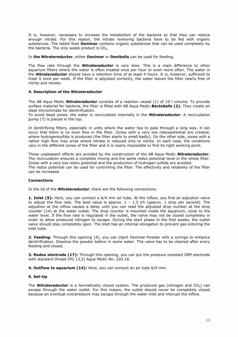
It is, however, necessary to increase the metabolism of the bacteria so that they can reduce
enough nitrate. For this reason, the nitrate removing bacteria have to be fed with organic
substances. The tablet feed Denimar contains organic substances that can be used completely by the bacteria. The only waste product is CO2.
In the Nitratereductor, either Denimar or Deniballs can be used for feeding.
The flow rate through the Nitratereductor is very slow. This is a main difference to other
aquarium filters where the water is often treated once per hour or even more often. The water in
the Nitratereductor should have a retention time of at least 4 hours. It is, however, sufficient to
treat it once per week. If the filter is adjusted correctly, the water leaves the filter nearly free of
nitrite and nitrate.
4. Description of the Nitratereductor
The AB Aqua Medic Nitratereductor consists of a reaction vessel (1) of 10 l volume. To provide
surface material for bacteria, the filter is filled with AB Aqua Medic Bactoballs (2). They create an ideal microclimate for denitrification.
To avoid dead zones, the water is recirculated internally in the Nitratereductor. A recirculation
pump (7) is placed in the top.
In denitrifying filters, especially in units where the water has to pass through a long way, it can
occur that there is no even flow in the filter. Zones with a very low redoxpotential are created,
where hydrogensulfide is produced (the filter starts to smell badly). On the other side, zones with a
rather high flow may arise where nitrate is reduced only to nitrite. In each case, the conditions
vary in the different zones of the filter and it is nearly impossible to find its right working point.
These unpleasant effects are avoided by the construction of the AB Aqua Medic Nitratereductor.
The recirculation ensures a complete mixing and the same redox potential level in the whole filter.
Zones with a very low redox potential and the production of hydrogen sulfide are avoided.
The redox potential can be used for controlling the filter. The effectivity and reliability of the filter
can be increased.
Connections In the lid of the Nitratereductor, there are the following connections:
1. Inlet (5): Here, you can connect a 6/4 mm air tube. At the inflow, you find an adjustion valve to adjust the flow rate. The best value is approx. 1 – 1.5 l/h (approx. 1 drop per second). The
adjustion at the inflow causes a delay until you can read the adjusted drop number at the drop
counter (14) at the water outlet. The drop counter is mounted inside the aquarium, close to the
water level. If the flow rate is regulated in the outlet, the valve may not be closed completely in
order to allow produced nitrogen to escape. During the start phase in the first weeks, the outlet
valve should stay completely open. The inlet has an internal elongation to prevent gas entering the
inlet tube.
2. Feeding: Through this opening (4), you can inject Denimar-Powder with a syringe to enhance denitrification. Dissolve the powder before in some water. The valve has to be cleaned after every
feeding and closed.
3. Redox electrode (17): Through this opening, you can put the pressure resistant ORP electrode with standard thread (PG 13,5) Aqua Medic No: 220.18.
4. Outflow to aquarium (14): Here, you can connect an air tube 6/4 mm. 5. Set-Up The Nitratereductor is a hermetically closed system. The produced gas (nitrogen and CO2) can
escape through the water outlet. For this reason, the outlet should never be completely closed
because an eventual overpressure may escape through the water inlet and interupt the inflow.
14
The Nitratereductor has to be placed in a way that water can flow off either directly back into the
aquarium or filter chamber. In a seawater aquarium, it is advantageous if the outflowing water is
flowing into the inlet of the protein skimmer or trickling filter. In the protein skimmer, the water is
saturated with oxygen before it flows back into the aquarium.
Inflow: The inflow into the reductor can be realized as a bypass from the main circulation pump with the included T-pieces (10). The flow rate is adjusted with valve (8) and drop counter (14).
6. Starting
Before starting, the Nitratereductor is filled with aquarium water and controlled for leaking and
the right position of the sealing. Take care for exact positioning of the O ring. Close the 8 clamps
tightly. The internal circulation pump can be switched on.
Connection to an existing aquarium
If the Nitratereductor is connected to an existing aquarium with a rather high nitrate level, the
inflow of aquarium water should not immediately be started. Bacterial growth is enhanced by
adding 4 dosing spoons Denimar-Powder. If, after 8 - 10 days, the nitrite has disappeared from
the reductor - a residual concentration of nitrate is harmless - the water flow can be switched on.
Connection to a new aquarium
If connected to a new aquarium, the bacteria does not have to be fed within the first 4 weeks, as
the nitrate forming bacteria Nitrosomonas and Nitrobacter need this time to develop and oxydize
the whole amount of ammonia and nitrite into nitrate.
Feeding The feeding has to be adjusted according to the nitrate loading of the aquarium. It can be
controlled with a redox probe (see options). In a normal loaded tank, one dosing spoon Denimar-
Powder per day is sufficient. It is possible to feed several dosing spoons (up to 5) at one time.
Then the filter needs no feeding for several days.
After some time, a slimy bacterial biomass is formed in the Nitratereductor. This is a normal
process. A high bacteria population ensures a high removal rate of nitrate.
7. Feeding with Deniballs AB Aqua Medic Deniballs are made of a biodegradable plastic material. This plastic material is also
produced biologically - the raw material is produced by bacteria. This new plastic material is
completely biodegradable. It can be used by denitrifying bacteria in the Nitratereductor to
remove nitrate. The Deniballs supply the surface area and food for the bacteria at the same time.
This means that a Nitratereductor filled with Deniballs has not to be fed for a longer period - up
to one year. The quantity of Deniballs which are necessary for a Nitratereductor depends on the
loading of the tank. For a normal loading, 1,5 - 2 l are enough. The rest of the filter is filled with
standard Bactoballs. Deniballs need - especially in a seawater tank - a longer period to reach
their full capacity. During this time (6 - 8 weeks) the Nitratereductor has to be fed with Denimar-
Powder.
8. Maintenance
1. Controlling the flow rate: The flow rate through the filter has to be checked regularly. The
optimum is at approx. 1 to 1,5 l/h. This has to be readjusted from time to time.
2. Recirculation pump: The recirculation pump has to be controlled regularly on clogging. The
pump housing has to be opened and the magnet with needle wheel removed. Both is cleaned
under fresh water and mounted again.
3. Cleaning: If the bacterial biomass has increased after some years, the Bactoballs can be
removed, cleaned with aquarium water and filled in again.
4. Renewal of Deniballs: The Deniballs have to be refilled/replaced once per year.
15
5. Feeding with Denimar: Without Deniballs: 1 dosing spoon/day.
6. From time to time, measurement of nitrite and nitrate concentrations in the outlet of the
Nitratereductor has to take place.
9. Options
With a redox potential control, the function of the Nitratereductor can be optimized and the reliability can be increased.
The optimal working point of the Nitratereductor can be determined by a measurement of the redox potential.
Denitrification and redox potential
The redox potential is a parameter which can be measured electronically. The value is a
measurement for the equilibrium between reducing and oxydizing reactions in the water.
The positive redox potential in the aquarium itself is kept at a few hundred Millivolt. In the
seawater tank, it should be between 300 and 440 mV. This high redox potential indicates that
oxydation reactions dominate over reduction reactions. Oxydation reactions are biochemical
reactions where a substance is oxydized, e. g. by oxygen.
A negative redox potential indicates the absence of oxygen and is lethal for most aquarium
inhabitants.
The biochemical conditions in the Nitratereductor differ completely from those in the aquarium: Nitrate has to be reduced to nitrogen gas. This is only possible if there is no oxygen dissolved in
the water.
The redox potential is low or even negative. The ideal range is between -50 and -250 mV.
If it exceeds -50 mV, the denitrification reaction may stop at the nitrite stage!
If it falls below -300 mV, all the nitrate is reduced. The bacteria then start to use sulphate. This is a
very undesired process because the end product of this reaction is Hydrogensulfide.
Hydrogensulfide (H2S) is toxic and smells very strange like fouling eggs.
If a little bit of Hydrogensulfide is entering the aquarium, this is not critical. It is immediately
oxydized to sulphate. The closed version of the Nitratereductor causes no problems with bad smell.
Controlling the Nitratereductor
The Nitratereductor can be controlled by the rate of feeding or the flow rate of water:
If the redox potential exceeds -50 mV or even gets positive, the dosage of food can be increased or
flow rate decreased.
If the redox potential sinks below -300 mV, the feeding can be reduced or flow rate increased.
Feeding with Denimar-Powder: You should keep the flow rate constant and vary the food supply.
10. Failures
Problems with denitrification are mostly caused by wrong adjustion of the flow and feeding rate.
They can only be determined by measurements of nitrite and nitrate concentrations in the filter or
by measurements of the redox potential.
- The pump produces noise: If the pump housing contains air or gas, this causes a strong noise. In this case, the pump is pumping little or no water and its cooling is insufficient. The pump may
overheat and be destroyed. The plastic elbow at the pump outlet has a small hole where air and
gas can escape. If this hole is blocked, it has to be cleaned by using a needle.
- Nitrite in the outlet of the filter: If the outlet of the filter contains high amounts of nitrite, the feeding rate is too low. Increase feeding or lower flow rate. In most cases, the redox potential is
too high (above -50 mV).
- Nitrate in the outlet of the filter. High residual concentrations of nitrate often occur together with high nitrite values. Caution! Most nitrate tests are disturbed by high nitrite concentrations! In this case, the redox potential is also too high. Increase feeding rates, decrease flow rate.
16
- Hydrogen sulphide in the outlet of the filter: The filter smells like fouling eggs. In most cases, the redox potential is too low (below –300 mV). Reduce the feeding, check the flow rate and
increase it, if necessary.
11. Warranty Should any defect in material or workmanship be found within 12 months of the date of purchase
AB Aqua Medic GmbH undertakes to repair or, at our option, replace the defective part free of
charge – always provided the product has been installed correctly, is used for the purpose that was
intended by us, is used in accordance with the operating instructions and is returned to us carriage
paid. The warranty term is not applicable on the all consumable products.
Proof of Purchase is required by presentation of an original invoice or receipt indicating the dealer’s
name, the model number and date of purchase, or a Guarantee Card if appropriate. This warranty
may not apply if any model or production number has been altered, deleted or removed,
unauthorised persons or organisations have executed repairs, modifications or alterations, or
damage is caused by accident, misuse or neglect.
We regret we are unable to accept any liability for any consequential loss.
Please note that the product is not defective under the terms of this warranty where the product,
or any of its component parts, was not originally designed and / or manufactured for the market in
which it is used.
These statements do not affect your statutory rights as a customer.
If your AB Aqua Medic GmbH product does not appear to be working correctly or appears to be
defective please contact your dealer in the first instance.
Before calling your dealer please ensure you have read and understood the operating instructions.
If you have any questions your dealer cannot answer please contact us.
Our policy is one of continual technical improvement and we reserve the right to modify and adjust
the specification of our products without prior notification.
AB AQUA MEDIC GmbH - Gewerbepark 24 - 49143 Bissendorf/Germany - Technical changes reserved – 08/2009
17
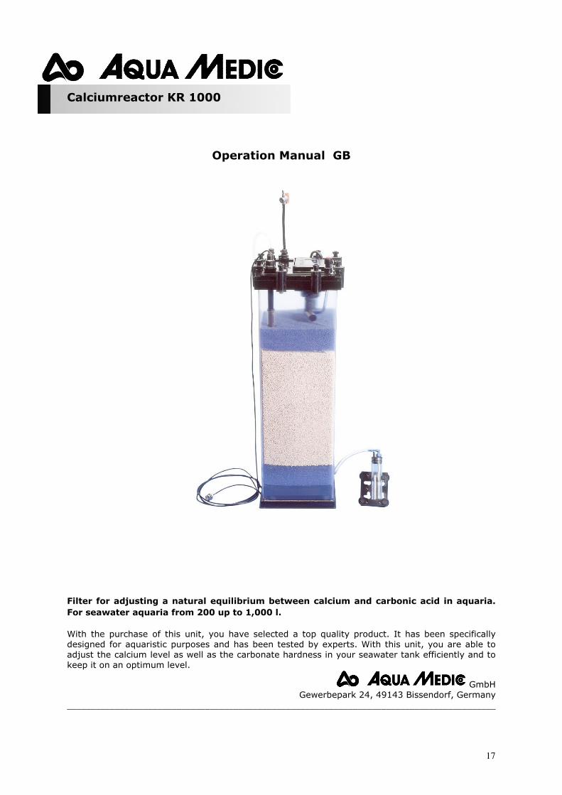
Calciumreactor KR 1000
Operation Manual GB
Filter for adjusting a natural equilibrium between calcium and carbonic acid in aquaria.
For seawater aquaria from 200 up to 1,000 l.
With the purchase of this unit, you have selected a top quality product. It has been specifically
designed for aquaristic purposes and has been tested by experts. With this unit, you are able to
adjust the calcium level as well as the carbonate hardness in your seawater tank efficiently and to
keep it on an optimum level.
GmbH
Gewerbepark 24, 49143 Bissendorf, Germany
__________________________________________________________________________________________
18
11
19
3
4
5
17
6
10
12
13
14
7
8
15
16
9
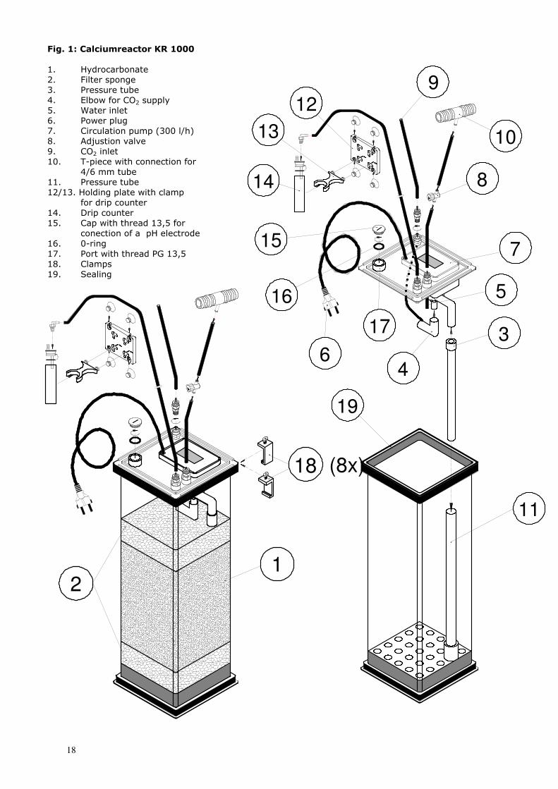
Fig. 1: Calciumreactor KR 1000
1. Hydrocarbonate
2. Filter sponge
3. Pressure tube
4. Elbow for CO2 supply
5. Water inlet
6. Power plug
7. Circulation pump (300 l/h)
8. Adjustion valve
9. CO2 inlet
10. T-piece with connection for
4/6 mm tube
11. Pressure tube
12/13. Holding plate with clamp
for drip counter
14. Drip counter
15. Cap with thread 13,5 for
conection of a pH electrode
16. 0-ring
17. Port with thread PG 13,5
18. Clamps
19. Sealing
(8x)18
12
19
1. Product description
The AB Aqua Medic Calciumreactor KR 1000 consists of the following parts:
- reaction vessel (height: 50 cm, volume approx. 10 l),
- filling with AB Aqua Medic Hydrocarbonate, fine grain
In the top of the filter, there are the water inflow and outflow, connection port for CO2 as well as
the circulation pump of the reactor.
2. Theory
The equilibrium between calcium and carbonic acid in a seawater aquarium is destroyed due to the
biological activity of the animals. For the construction of their calcareous skeletons, they take
calciumcarbonate out of the water. As a result, it comes to a lack of calcium and an increase of the
pH-value.
The AB Aqua Medic Calciumreactor is a module for the adjustment of the natural equilibrium
between calcium and carbonic acid in the aquarium. It is filled with Hydrocarbonate, a highly
purified calciumcarbonate. Because this calciumcarbonate is not soluble at pH-values common in
seawater tanks, it is necessary to blow carbonic acid into the reactor. This results in a local drop of
the pH-value and simultaneously to the dissolving of calciumbicarbonate.
To avoid an overdosage, the addition of carbonic acid can be controlled by using a pH Controller.
This method does not change the pH-value of the aquarium water.
Chemical reaction
CaCO3 + CO2 + H2O -----> Ca(HCO3)2
Calciumcarbonate + Carbonic acid + Water ------> Calciumbicarbonate
This reaction only takes place at neutral resp. acidic pH-values. At pH 8.2, calciumcarbonate is not
soluble.
Calciumbicarbonate is easily soluble. It can be directly taken up by animals and plants and
integrated into their skeletons. By doing this, calciumbicarbonate is changed back to
calciumcarbonate. During this back reaction, CO2 is released which is used by Zooxanthellae for
photosynthesis.
3. Working principle
The Calciumreactor is supplied with water from the top. The flow rate should be adjusted
between 1 and 3 l/h. The circulation pump placed in the top of the reactor circulates the water
internally. The CO2 is connected at the injection port on top of the reactor. The pump sucks on CO2.
Through the rotation of the patented AB Aqua Medic Needle Wheel, the CO2 will be completely
dissolved in the water. Then the CO2 enriched water is pumped below the Hydrocarbonate and
finally circulated. Thereby, calciumbicarbonate is extracted from the Hydrocarbonate. This is
exactly the combination which corals need for their growth.
The outflow is located in the top of the filter. From there, the water flows into the aquarium or back
to the filter tank. The carbonic acid can be added from a pressure bottle.
20
4. Set-up
This version of the Calciumreactor is a closed system. The reactor can be installed below the
aquarium from where the water can flow into a filter chamber or back into the aquarium.
Water inflow:
From the circulation pump which pumps the filtered water back into the aquarium, a bypass is
performed to the water inlet of the Calciumrecator with a 6 mm pipe. The inflowing water
quantity has to be adjusted in a way that approx. 1 - 3l/h (1 - 4 drops/sec.) flow through the 6 mm
pipe into the reactor. The adjustment and the quantity of CO2 depends on the aquarium size and
the calcium requirements of the animals. The quantity of calcium can be ajusted via a bubble
counter (not included).
5. Starting
As soon as the Calciumreactor is placed in the right position and all connections are ready, The
water flow can be started. Then the reactor is filled up with water until water comes out of the
outlet.
If the Calciumreactor is placed beside the filter tank or above the aquarium, all connections and
the reactor itself must be controlled for tightness. Then the CO2 can be switched on. The quantity
of CO2 has to be adjusted so that the pH-value in the aquarium does not drop below pH 7.8. Within
the reactor itself, the pH-value should drop to pH 5.9 – 6.0. It is possible to control the pH-value in
the reactor: in the top are holes to put in a pH electrode.
It is ideal to use a pH-Controller with magnetic valve, e. g. an AB Aqua Medic pH Controller, to
adjust the pH-value in the aquarium reliably. The value should be adjusted between 8.0 and 8.2,
depending on the calcium demand of the animals. The back flow of the calciumbicarbonate
enriched water into either the aquarium or the filter tank should be directed to a well-flushed place
in order to mix it immediately with the aquarium water. This avoids instabilities of the pH-value.
Because of the limited water flow through the Calciumreactor, the pH lowering in the aquarium is
only minimal. It will be sufficient to check the pH value in the tank occasionally and to refrain from
a continuous adjustment.
6. Maintenance
The AB Aqua Medic Hydrocarbonate is consumed by the chemical reaction and has to be refilled
from time to time. Every 2 years it should be replaced completely. Also the flow rate should be
checked regularly. It has to be re-adjusted with a drop counter. In case of polluted water the
adjustment valve in the water inflow has to be cleaned from time to time.
21
7. Warranty
Should any defect in material or workmanship be found within 12 months of the date of purchase
AB Aqua Medic GmbH undertakes to repair or, at our option, replace the defective part free of
charge – always provided the product has been installed correctly, is used for the purpose that was
intended by us, is used in accordance with the operating instructions and is returned to us carriage
paid. The warranty term is not applicable on the all consumable products.
Proof of Purchase is required by presentation of an original invoice or receipt indicating the dealer’s
name, the model number and date of purchase, or a Guarantee Card if appropriate. This warranty
may not apply if any model or production number has been altered, deleted or removed,
unauthorised persons or organisations have executed repairs, modifications or alterations, or
damage is caused by accident, misuse or neglect.
We regret we are unable to accept any liability for any consequential loss.
Please note that the product is not defective under the terms of this warranty where the product,
or any of its component parts, was not originally designed and / or manufactured for the market in
which it is used.
These statements do not affect your statutory rights as a customer.
If your AB Aqua Medic GmbH product does not appear to be working correctly or appears to be
defective please contact your dealer in the first instance.
Before calling your dealer please ensure you have read and understood the operating instructions.
If you have any questions your dealer cannot answer please contact us.
Our policy is one of continual technical improvement and we reserve the right to modify and adjust
the specification of our products without prior notification.
AB AQUA MEDIC GmbH - Gewerbepark 24 - 49143 Bissendorf/Germany - Technical changes reserved – 08/2009
22
Ocean Runner PH 2000/2500/3000
Operation Manual GB
Current pump for fresh and salt water aquariums.
In purchasing this pump, you have selected a top quality product. It has been specifically
developed for aquarium use and extensively tested by experts.
GmbH
Gewerbepark 24, 49143 Bissendorf, Germany
_________________________________________________________________________________________
23
1. Features
The Ocean Runner PH series of magnetically coupled power head pumps are very quiet in operation. They have fully encapsulated synchronous motors and can operate completely safely
either submerged or out of water. The polished ceramic shaft and bearing is practically wear
resistant, ensuring a long operating life. The pumps can easily be taken apart for cleaning.
All materials are salt water resistant.
IMPORTANT NOTE:
Only operate the pump at the voltage shown on the product label.
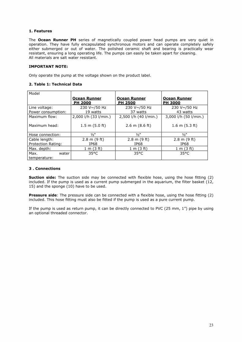
2. Table 1: Technical Data
Model
Ocean Runner PH 2000
Ocean Runner PH 2500
Ocean Runner PH 3000
Line voltage:
Power consumption:
230 V~/50 Hz
19 watts
230 V~/50 Hz
37 watts
230 V~/50 Hz
43 watts
Maximum flow:
Maximum head:
2,000 l/h (33 l/min.)
1.5 m (5.0 ft)
2,500 l/h (40 l/min.)
2.6 m (8.6 ft)
3,000 l/h (50 l/min.)
1.6 m (5.3 ft)
Hose connection: ½“ ½“ ½“
Cable length:
Protection Rating:
2.8 m (9 ft)
IP68
2.8 m (9 ft)
IP68
2.8 m (9 ft)
IP68
Max. depth: 1 m (3 ft) 1 m (3 ft) 1 m (3 ft)
Max. water
temperature:
35°C 35°C 35°C
3 . Connections Suction side: The suction side may be connected with flexible hose, using the hose fitting (2) included. If the pump is used as a current pump submerged in the aquarium, the filter basket (12,
15) and the sponge (10) have to be used.
Pressure side: The pressure side can be connected with a flexible hose, using the hose fitting (2) included. This hose fitting must also be fitted if the pump is used as a pure current pump.
If the pump is used as return pump, it can be directly connected to PVC (25 mm, 1”) pipe by using
an optional threaded connector.
24
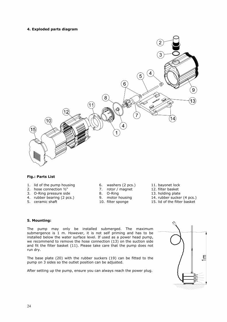
4. Exploded parts diagram
Fig.: Parts List 1. lid of the pump housing
2. hose connection ½“
3. O-Ring pressure side
4. rubber bearing (2 pcs.)
5. ceramic shaft
6. washers (2 pcs.)
7. rotor / magnet
8. O-Ring
9. motor housing
10. filter sponge
11. bayonet lock
12. filter basket
13. holding plate
14. rubber sucker (4 pcs.)
15. lid of the filter basket
5. Mounting: The pump may only be installed submerged. The maximum
submergence is 1 m. However, it is not self priming and has to be
installed below the water surface level. If used as a power head pump,
we recommend to remove the hose connection (13) on the suction side
and fit the filter basket (11). Please take care that the pump does not
run dry.
The base plate (20) with the rubber suckers (19) can be fitted to the
pump on 3 sides so the outlet position can be adjusted.
After setting up the pump, ensure you can always reach the power plug.
25
6. Maintenance / Cleaning CAUTION: Disconnect the power before you start any work on the pump.
The pump is designed to have a low maintenance requirement and, under normal conditions, will
be very reliable. However, the filter housing and all rotating parts must be cleaned regularly (1 to
5).
Remove the pipe connections and undo the bayonet (6) on the pump housing. Now remove the
suction connection (7). Caution: This part is fixed tightly because it has an “O” ring seal and must be removed carefully so as not to break the ceramic shaft (4).
The complete impeller (4 - 7) can now be taken out, cleaned under running water and be re-
assembled.
7. Failures If the pump fails to operate check the power connection and fuse. If no fault is found, the pump
may be blocked and must be cleaned – see maintenance / cleaning above. If the pump is noisy, the pump head (1 to 8) has to be cleaned.
8. Warranty
Should any defect in materials or workmanship be found within twelve months of the date of
purchase AB Aqua Medic GmbH undertakes to repair, or at our option replace, the defective part
free of charge – always provided the product has been installed correctly, is used for the purpose
that was intended by us, is used in accordance with the operating instructions and is returned to us
carriage paid.
Proof of purchase is required by presentation of the original invoice or receipt indicating the
dealer’s name, the model number and date of purchase, or a guarantee card if appropriate. This
warranty may not apply if any model or production number has been altered, deleted or removed,
unauthorised persons or organisations have executed repairs, modifications or alterations or
damage is caused by accident, misuse or neglect.
We regret we are unable to accept any liability for any consequential loss.
Please note that the product is not defective under the terms of this warranty where the product,
or any of its component parts, was not originally designed and / or manufactured for the market in
which it is used.
These statements do not affect your statutory rights as a customer.
If your AB Aqua Medic GmbH product does not appear to be working correctly or still appears to be
defective having followed the instructions in 6. & 7. above, please contact your dealer in the first
instance.
Before calling your dealer please ensure you have read and understood the operating instructions.
If you have any questions your dealer cannot answer please contact us
We reserve the right to make technical changes to this product.
AB AQUA MEDIC GmbH - Gewerbepark 24 - 49143 Bissendorf/Germany - Technical changes reserved – 08/2009
Safety advice:
The pump is constructed for indoor aquarium use only. Before working on the aquarium or pump, the power plug must be disconnected from the mains. The connection cable and the power plug must not be changed. If the power cable is damaged, the pump must not be taken into operation. If the pump is used submerged, the filter (11, 12), hose and/or hose connection (13) must be used.
26
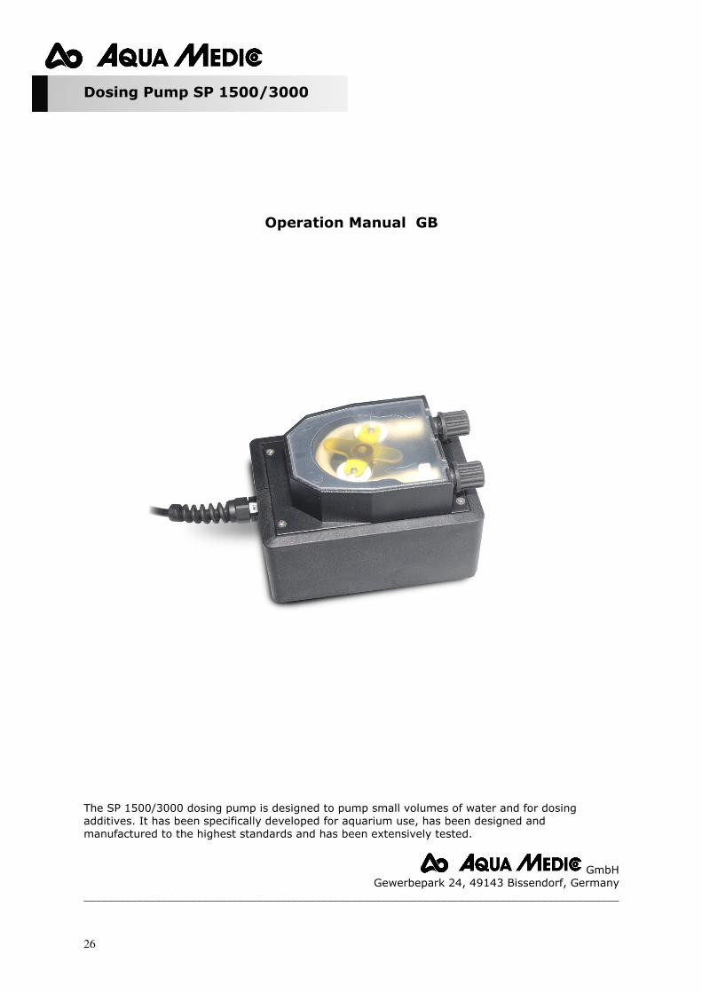
Dosing Pump SP 1500/3000
Operation Manual GB
The SP 1500/3000 dosing pump is designed to pump small volumes of water and for dosing additives. It has been specifically developed for aquarium use, has been designed and
manufactured to the highest standards and has been extensively tested.
GmbH
Gewerbepark 24, 49143 Bissendorf, Germany
__________________________________________________________________________________________
27
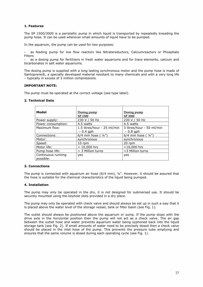
1. Features
The SP 1500/3000 is a peristaltic pump in which liquid is transported by repeatedly kneading the
pump hose. It can be used wherever small amounts of liquid have to be pumped.
In the aquarium, the pump can be used for two purposes:
- as feeding pump for low flow reactors like Nitratereductors, Calciumreactors or Phosphate
Filters
- as a dosing pump for fertilizers in fresh water aquariums and for trace elements, calcium and
bicarbonates in salt water aquariums.
The dosing pump is supplied with a long lasting synchronous motor and the pump hose is made of
Santoprene®, a specially developed material resistant to many chemicals and with a very long life
– typically in excess of 3 million compressions.
IMPORTANT NOTE: The pump must be operated at the correct voltage (see type label).
2. Technical Data
Model Dosing pump
SP 1500
Dosing pump
SP 3000
Power supply: 230 V / 50 Hz 230 V / 50 Hz
Power consumption: 4.5 watts 4.5 watts
Maximum flow: 1.5 litres/hour - 25 ml/min
– 0.4 gph
3 litres/hour - 50 ml/min
– 0.8 gph
Connections: 6/4 mm hose ( ¼”) 6/4 mm hose ( ¼”)
Motor: synchronous synchronous
Speed: 10 rpm 20 rpm
Motor life: > 10,000 hrs >10,000 hrs
Pump hose life: > 3 Million turns >3 Million turns
Continuous running
possible:
yes yes
3. Connections
The pump is connected with aquarium air hose (6/4 mm), ¼“. However, it should be assured that
the hose is suitable for the chemical characteristics of the liquid being pumped.
4. Installation
The pump may only be operated in the dry, it is not designed for submersed use. It should be
securely mounted using the keyhole slots provided in a dry place.
The pump may only be operated with check valve and should always be set up in such a way that it
is placed above the water level of the storage vessel, tank or filter basin (see Fig. 1).
The outlet should always be positioned above the aquarium or sump. If the pump stops with the
drive axle in the horizontal position then the pump will not act as a check valve. The air gap
between the outlet hose and water prevents aquarium water being syphoned back into the liquid
storage tank (see Fig. 2). If small amounts of water need to be precisely dosed then a check valve
should be placed in the inlet hose of the pump. This prevents the pressure tube emptying and
ensures that the same volume is dosed during each operating cycle (see Fig. 1).
28
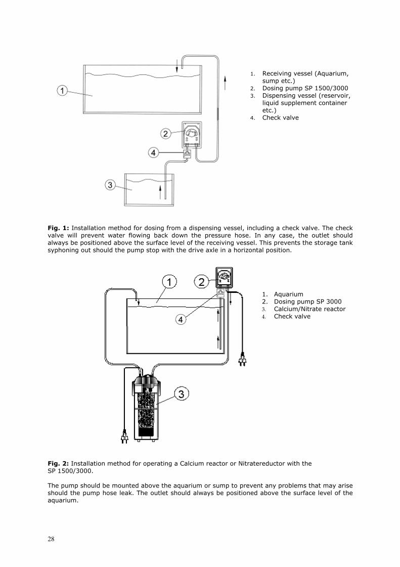
1. Receiving vessel (Aquarium,
sump etc.)
2. Dosing pump SP 1500/3000
3. Dispensing vessel (reservoir,
liquid supplement container
etc.)
4. Check valve
Fig. 1: Installation method for dosing from a dispensing vessel, including a check valve. The check valve will prevent water flowing back down the pressure hose. In any case, the outlet should
always be positioned above the surface level of the receiving vessel. This prevents the storage tank
syphoning out should the pump stop with the drive axle in a horizontal position.
1. Aquarium
2. Dosing pump SP 3000
3. Calcium/Nitrate reactor
4. Check valve
Fig. 2: Installation method for operating a Calcium reactor or Nitratereductor with the SP 1500/3000.
The pump should be mounted above the aquarium or sump to prevent any problems that may arise
should the pump hose leak. The outlet should always be positioned above the surface level of the
aquarium.
29
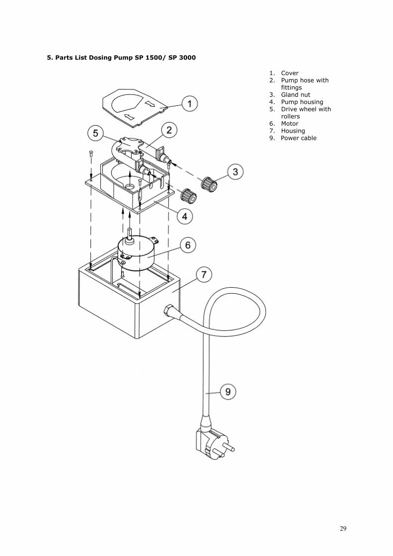
5. Parts List Dosing Pump SP 1500/ SP 3000
1. Cover
2. Pump hose with
fittings
3. Gland nut
4. Pump housing
5. Drive wheel with
rollers
6. Motor
7. Housing
9. Power cable
30
6. Control The synchronous motor of the pump operates at a fixed speed of 20 rpm. This cannot be changed.
If smaller amounts of water are to be dosed or a smaller flow rate is required, the SP 1500/3000
can be switched on and off for varying periods of times. For exact dosing, a digital timer switch,
programmable in minutes, should be used. Important: Never use the pump together with a valve. If you want to reduce the flowrate, use a time switch (15 minutes “On”, 15 minutes “Off” = ½ flow rate).
7. Maintenance
The pump hose and the motor are consumable and have to be maintained and changed regularly.
Pump hose: The pump hose has a lifetime of approx. 3 million rotations and after this usage, it
needs replacement. If the pump is operated continously, the hose should be changed every 3 – 4
months. We recommend to use only an original Aqua Medic spare pump hose assembly which is
supplied complete with fittings.
Grease: Before the hose is installed it has to be greased. The pump will only operate properly if the
hose is effectively greased.
Heat: During continous operation the motor may heat up as high as 70°C. This is normal and has
no effect on performance or the life. However, too little grease on the pump hose may cause
malfunction of the motor and overheating.
Drive wheel with rollers: The plastic drive wheel and the rollers are designed for a long life.
Nevertheless, it may become necessary to change it. The change can be done the following way:
Remove the pump hose by pushing the fittings out of the housing. The drive wheel can now be
pulled off the shaft as it is a pressed fitting.
Motor: The motor has a lifetime of >10,000 hours. To replace the motor remove the drive wheel
assembly. Undo the 4 screws in the backplate. Now remove the backplate and protection plate.
Undo the power cable connection from the connector block and remove the 2 screws securing the
motor to the housing. To fit the new motor reverse the above process.
8. Warranty
Should any defect in material or workmanship be found within 12 months of the date of purchase
AB Aqua Medic undertakes to repair or, at our option, replace the defective part free of charge –
always provided the product has been installed correctly, is used for the purpose that was intended
by us, is used in accordance with the operating instructions and is returned to us carriage paid. The
warranty term is not applicable on the all consumable products. Proof of Purchase is required by
presentation of an original invoice or receipt indicating the dealer’s name, the model number and
date of purchase, or a Guarantee Card if appropriate. This warranty may not apply if any model or
production number has been altered, deleted or removed, unauthorised persons or organisations
have executed repairs, modifications or alterations, or damage is caused by accident, misuse or
neglect. We regret we are unable to accept any liability for any consequential loss. Please note that
the product is not defective under the terms of this Warranty where the product, or any of its
component parts, was not originally designed and / or manufactured for the market in which it is
used. These statements do not affect your statutory rights as a customer. If your AB Aqua Medic
product does not appear to be working correctly or appears to be defective please contact your
dealer in the first instance. Before calling your dealer please ensure you have read and understood
the operating instructions. If you have any questions your dealer cannot answer please contact us
Our policy is one of continual technical improvement and we reserve the right to modify and adjust
the specification of our products without prior notification.
AB AQUA MEDIC GmbH - Gewerbepark 24 - 49143 Bissendorf/Germany -Technical changes reserved – 05/2009
Safety instructions The pump may only be used indoors. Before undertaking any work on the pump, disconnect the power plug from the mains!