Embed Size (px)
Citation preview

1
Reel-to-reel wet coating by variation in solvents and compounds of
photoactive inks for polymer solar cell production
Mario Schrödner a, Steffi Sensfuss
a, Hannes Schache
a, Karin Schultheis
a, T. Welzel
a, K.
Heinemann a, R. Milker
b, J. Marten
b, Lars Blankenburg
a,*
a) Thüringisches Institut für Textil- und Kunststoff-Forschung e.V. (TITK), An-Institut der Technischen Universität Ilmenau, Breitscheidstraße 97, 07407 Rudolstadt (Germany); b) POLY-CHEM AG, Chemiepark Bitterfeld-Wolfen, OT Greppin, Farben-straße, Areal B, 06803 Bitterfeld-Wolfen (Germany) * Corresponding author. Tel.: +49-3672-379558; Fax: +49-3672-379379. E-mail address: [email protected] (L. Blankenburg)
Abstract
In this paper we report about progress in reel-to-reel (R2R) solvent-based production of
polymer solar cells. To be aware of the huge advantages in energy and material saving
the hole-injection and the photoactive layer were successfully prepared by continuous
slot-die wet coating of low viscosity inks. It was aimed to reach higher values of light
power conversion efficiencies for reducing the gap between production under best
laboratory conditions on rigid substrates in comparison to more robust large-scale
coating in practice. For this, solvent systems and photoactive materials (electron-
acceptor) were varied and applied with 1 m/min at the laboratory R2R-coating machine
and coating width up to 8 cm. Polymer solar cells (PSCs) manufactured out of the so
coated foils reach in maximum 3.2 % light power conversion efficiency (AM1.5) In this
context, also reel-to-reel wet coating with [6,6]-phenyl-C61-butyric acid methyl ester
(PCBM) systems with change to non-halogenated inks were successfully done for
learning technological suitability and optionally future transfer to the “new” system.
Keywords: reel-to-reel, organic photovoltaics, polymer solar cells, wet coating, slot die
coating
2
1. Introduction
Organic photovoltaics (OPV), particularly with regard to polymer solar cells (PSCs),
that are producible out of solution, is more than ever in focus of research.[1-3] With the
development of new materials for PSCs photoactive layer - light absorbing polymers[4-7]
as well as electron-accepting fullerenes[8-12] - and with actually reached performances
with more than 8 % to 10 % light power conversion efficiency[13,14] the potential for
competition with inorganic thin film PV is given. At the moment the focus of research
is on new low-bandgap polymers[15-21] to increase and broaden the light absorption in
sun spectrum. But also more practical and technological approaches come now on
top.[22] To take care of the competitive advantages there is at present a huge interest to
realize PSCs on flexible substrates[13-27], to produce without indium-tin-oxide (ITO)[28-
31], because of the ITO-availability and the high costs[32], and to develop high-barrier
materials (optically transparent and mechanically flexible)[33,34] to avoid the degradation
of the sensitive organic compounds caused by environmental influences and hence to
ensure longer lifetime of PSC modules. An important feature is the production process
itself. It is aimed to establish reel-to-reel (R2R) processes[35-37] by using up-scaling
techniques out of solution[38,39] like slot-die coating[40,41], brush painting[42] or gravure
printing[43,44] for example.
In own very first experiments in R2R coating modus feasibility could be demonstrated
with only one solvent for photoactive layer formation and small coating width.[36] To
establish a more stable coating process with higher throughput (coating width) it was
now intended to check at the one hand alternative useful solvents and solvent-mixtures
as well as new materials at the other hand for increasing performance of resulting PSC
in production line. With this motivation we report our results in producing PSC, in
which two functional layers, the hole-conducting and the photoactive one, were

3
successfully prepared by continuous R2R wet coating of low viscosity solutions and
dispersions on ITO-coated PET substrates. In this article we summarize our
investigations made on a small-scale coating machine (LBA-200) using R2R-slot-die-
coating technique (Fig. 1), knowing about their beneficial potential to fulfill future
industrial production requirements. The chosen technology convince with features like
continuous coating, low temperature process (energy saving), large-area-coating (2 m
coating width and web speeds up to 600 m/min in principle), pre-metered volume flow
avoids dissipation of material (resources saving) and enables exactly adjustable layer
thickness control (concentration, delivery flow rate, web speed, coating width),
homogenous layer thicknesses are as much achievable as dry layer thicknesses < 1 µm,
because of ability to apply low viscosity and low concentrated inks, only to name some
of the advantages.[45-47]
All of the here described PSCs are fabricated according to the commonly used concept
of bulk heterojunction (BHJ), i.e. blending of polymeric electron-donator with fullerene
-acceptor in the photoactive layer.[48-51]
Halogenated solvents are widely used in PSC production because of combining best
solubility properties for usual light absorbing polymers and electron-accepting
compounds with good film forming behavior, meaning also effective nanophase-
separation[52] in drying process to give finally good power conversion efficiencies. In
general, chlorobenzene and 1,2-dichlorobenzene are the solvents of choice for dis-
continuous spin-coating on rigid ITO-glass substrates for top PSC.[53] However, in tech-
nological and industrial issues it is tried to replace such solvents by non-halogenated
ones because of environmental (toxicity) and aggressive properties against technical
equipment and machines[54,55]. In the work described here, we tested as one issue
halogen-free o-xylene in comparison to the halogenated standard systems in R2R modus
for optional later transfer to best working photoactive systems, what was applied R2R
4
as the second item. Here the common fullerene is replaced by the best state of the art
material. For this system the continuously coating behavior (like wetting, drying) was
studied for showing that even on flexible foils higher PSC efficiencies become possible
for reducing the discrepancy between preparation under ideal conditions in lab in
comparison to production with robust and more industrial profitable needs.
2. Experimental
2.1 Materials
Regioregular poly-3-hexylthiophene (P3HT, OS2100) was purchased from Aldrich and
used as received. [6,6]-Phenyl-C61-butyric acid methyl ester (PCBM) was obtained
from Solenne. Bisindene-C60 was synthesized according to He et al.[56] Plexcore
PV2000 system was obtained from Plextronics. All the photoactive solutions were
filtered before use. PEDOT:PSS (poly(3,4-ethylene-dioxythiophene):polystyrene-
sulfonate) was obtained from Heraeus Clevios GmbH (Clevios PH and 4083) and was
filtered prior to use.
ITO coated glass was purchased from Merck (13 Ωsq) and ITO-PET foil (125 µm thick,
40 m, different width) from Southwall. The ITO thickness was 100 nm and the surface
resistance 50 Ωsq.
2.2. Methods
Surface energies were determined with a Krüss contact angle/ surface tension measuring
instrument DSA100. The thicknesses of the films were determined by a Woollam
spectral ellipsometer M44 (600-1200 nm); surface visualization was made by AFM with
the Standard Level AFM (ANFATEC Instruments AG; Oelsnitz; scan: 30 µm, lateral: <
5 nm, z: < 0.5 nm). For measurements of light transmission a Thermo Spectronic

5
UNICAM UV 300 spectrometer was used. Rheological investigations were done at a
rotation-rheometer Rheostress 100 (Haake, DG 41 (double slit) at 25°C, shear gradient
0.5 to 40 s-1); zero shear viscosities could be obtained by creep-measurements (shear
stress 0.5 Pa).
For the continuous wet coating an in-house R2R laboratory coating machine LBA-200
was used as described in a former publication[36]. Also the R2R-produced PEDOT:PSS
layers were prepared like explained there. The slot die coating is variable in die lip gap
and die lip to substrate gap as well as caster arrangement/ angle and can be understood
as a combination of extrusion coating with bulge and with pulling, as known[45,57].
Spincoating was done on a semitec CPS20 machine in clean room (air). For
photovoltaic devices preparation in R2R mode the substrates were taken as roll-ware
without any cleaning procedures. Completions with top-electrodes were done for all
R2R-coated solar cells discontinuously in a glove box. Calcium and aluminum
(cathode) were thermally deposited (15 nm Ca, 50 nm Al) through a shadow mask in
vacuum (MB EVAP M. Braun), which defines a device area of 0.25 cm². J/V curves
were recorded with a Keithley SMU 2400 Source Meter by illuminating the cells from
the ITO side with 100 mW/cm² white light from a Steuernagel solar simulator to realize
AM1.5 conditions. A mono-crystalline silicon solar cell, calibrated at ISE Freiburg,
Germany was used as reference cell to confirm stabilization of 100 mW/cm²
illumination. All cells were prepared under ambient conditions (air) and annealed as
well as measured (because of the sensitive Ca) in inert atmosphere (Ar).
3. Results and discussion
3.1 P3HT:PCBM: R2R-coating and variation in solvents

6
Alternative literature known solvent variants with reduced halogen-content for solar cell
preparation are described for chloroform with ethyl alcohol[58], toluene with
chloroform[59], p-xylene[60,61], o-xylene[62], tetralin[63,64] or o-dichlorobenzene with
mesitylene[64]. In these cases remarkable efficiencies up to around 4 % could be
observed for devices coated on glass. In this sense not only the mentioned simple
replacement of solvents was aimed but also certain effects like pre-aggregation (fibers)
or low-/high-boiling combination (slow drying) to influence morphology. R2R-
application of non-halogenated system on ITO-PET had been described with 0.7 %
efficiency (module with 3 solar cells á 1 x 7 cm²) as well.[55] Film forming and also film
drying are not trivial and depend on the respective material (material combination). A
lot of different parameters (surface energies, temperatures, etc.) should be well matched
to stay in the coating window and to obtain a high quality dry film.[65]
For own R2R-coating o-xylene (Xy) was tested in comparison to chlorobenzene (CB)
and o-dichlorobenzene (DCB), that are known for best solubility and film-forming
ability in spin-coating process. The question was, whether DCB can be taken in R2R-
wet-coating process and what are the characteristics of PSCs manufactured out of it
versus R2R-proofed CB. And as second issue, can halogen-free solvent work as well as
CB? For this, the “old” standard system consisting of poly(3-hexylthiophene) (P3HT)
and phenyl-C60-butyric acid methyl ester (PCBM) was solved in ratio 1:0.8 (wt./wt.)
and 1.2 wt.% in each of the solvents. Xy was chosen because of good solving-character
for a non-halogenated solvent in combination with moderate boiling temperature ( bp =
144 °C) - higher than toluene and chloroform to give the film the time it needs for right
phase-separation, but low enough to dry at air in relatively short terms. The latter is very
important in technological considerations, especially for the engaged machinery. After
the caster-application the sensitive wet-foil is transported relatively straight and
horizontal into the dryer region and up to the moment the film is touch-dry mechanical
7
stress from web guide rolls should be strictly avoided, elsewhere inhomogeneities
occur. Anyway, the setup of the LBA200 requires a relatively fast film drying caused by
only 3 m horizontal drying zone. In principle this is no problem for very thin wet-
thicknesses of around 5-10 µm and also for other coatings that have the opportunity for
solidification by cross-linking due to UV-radiation or heat input by IR-radiation.
All the different solvent based inks of the here described coating were applied by slot
die caster with same dosage giving nominal 9 µm wet and around 100 nm dry film
thicknesses. Coating width was 5 cm and the coatings itself showed good wetting on the
R2R-coated PEDOT:PSS-ITO-foil. The wet film quality directly after application was
good in all cases. For hole-injection as well as photoactive layer formation out from Xy
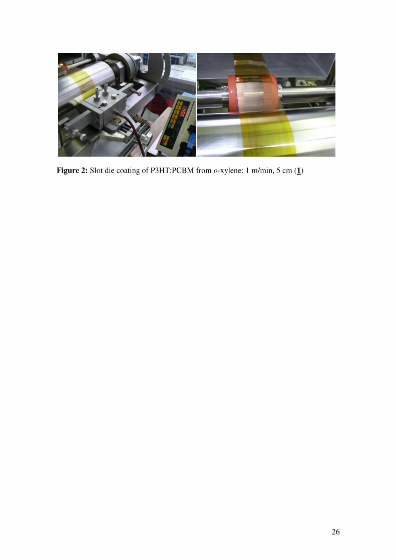
see Figure 2 as sample.
To avoid fast degradation at air, the films were only allowed to dry at ambient
temperatures, except DCB with a boiling point of 180 °C, what was also tested in one
trial to dry with the help of an additional IR-heater (200 W).
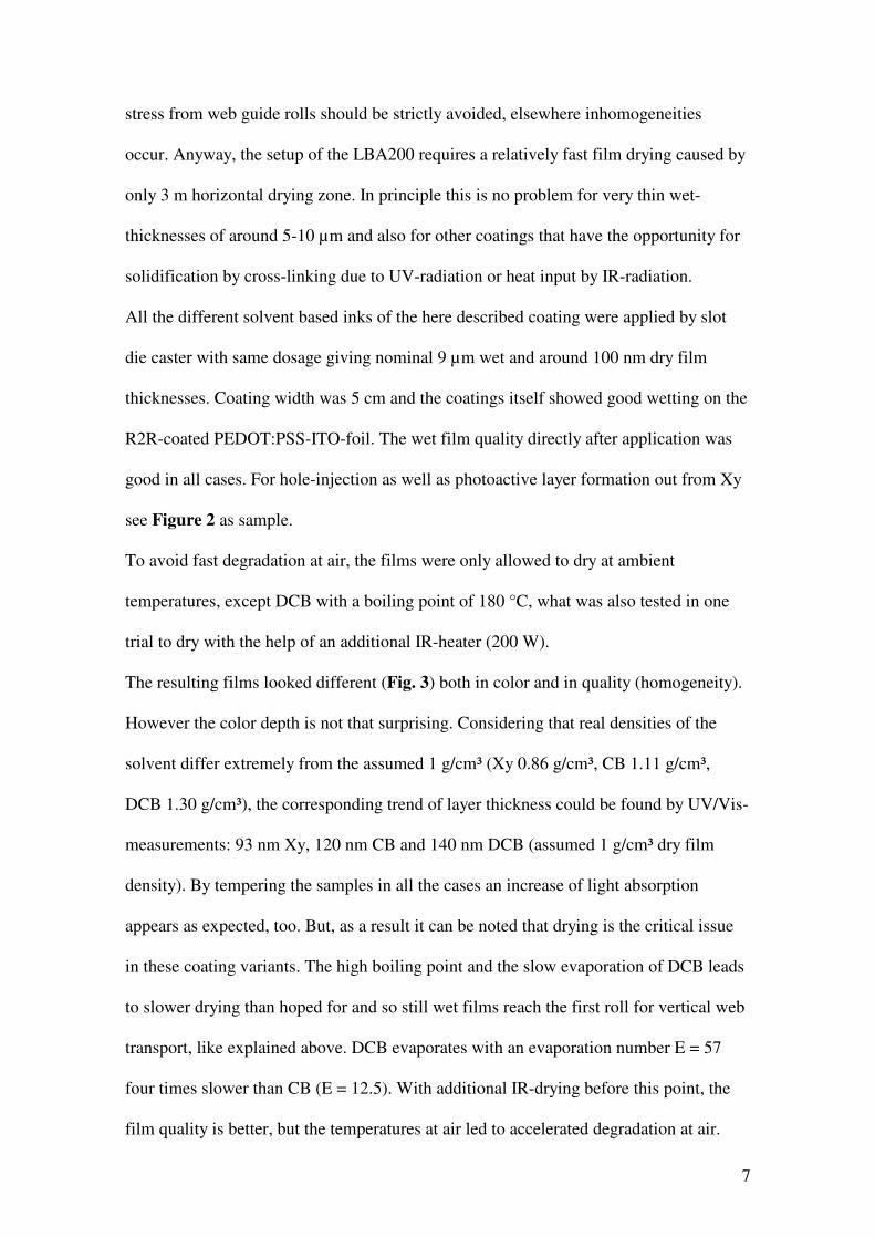
The resulting films looked different (Fig. 3) both in color and in quality (homogeneity).
However the color depth is not that surprising. Considering that real densities of the
solvent differ extremely from the assumed 1 g/cm³ (Xy 0.86 g/cm³, CB 1.11 g/cm³,
DCB 1.30 g/cm³), the corresponding trend of layer thickness could be found by UV/Vis-
measurements: 93 nm Xy, 120 nm CB and 140 nm DCB (assumed 1 g/cm³ dry film
density). By tempering the samples in all the cases an increase of light absorption
appears as expected, too. But, as a result it can be noted that drying is the critical issue
in these coating variants. The high boiling point and the slow evaporation of DCB leads
to slower drying than hoped for and so still wet films reach the first roll for vertical web
transport, like explained above. DCB evaporates with an evaporation number E = 57
four times slower than CB (E = 12.5). With additional IR-drying before this point, the
film quality is better, but the temperatures at air led to accelerated degradation at air.

8
For overview of R2R-conditions and the manufactured solar cells out of it see Table 1 –
PSC 1-4. The appropriate J/V-curves to the summarized values are depicted in Figure
5. Best values could be obtained from CB (4). PSCs processed from DCB without IR-
drying (3) still give light power conversion efficiencies more than 1 %, but they are not
suitable for larger area/module-fabrication because of the poor surface quality. The
improved homogeneity of the surface with IR-radiation (2) is accompanied with a
counterproductive drop in the efficiency. The fill factor (FF) decreases indicating bad
morphology and/or degradation. However, remarkable 1.17 % for the Xy-variant (1)
could be recorded. The coating out of this solvent can bee seen as a real alternative for
photoactive-layer formation: good film quality and non-halogenated solvent production.
In ongoing research we will try thicker Xy-variants and better photoactive material
systems to improve the performance of this promising solvent.
In Figure 6 the surfaces resulting out of the different four experiments can be
compared. It can obviously be seen, that the roughness differs extremely. Both, a too
smooth (DCB+IR, 2) and also a too rough surface (DCB 3) – also standing for degree of
phase-separation (too less of nano-phase separation or too large clusters minimizing
D/A-interface layer) of the blend components, that is tricky to regulate but extremely
crucial for functionality in solar cell – are not wished.[66-68,2] Surface roughness with
maximum peaks in the range of 20-40 µm (Xy and CB) seem to be the best solution.
The determined results in layer formation and solar cell efficiencies are valid for the
special kind of machinery and technology-type. By using other coating machines, that
differ in construction (scales, web guide, drying, inert atmosphere), also a changed
ranking is possible. The investigation done can serve as help for their construction.
9
3.2 A “new” system: P3HT and bisindene-C60 - R2R-coating
To come closer the high values and performances of PSC, produced in lab-scale under
best conditions as reported in the last two years, the “new” system: P3HT and
bisindene-C60, known for their ability to manage more than 6 % on ITO-glass[9], was
chosen for testing suitability R2R-slot die technique for future production.
At the beginning solar cells on rigid substrates were prepared for proofing optimum
capacity of the donator-acceptor system. For this commercial inks from Plextronics®
were applied. The certain hole-injection layer (from Plextronics: Plexcore PV2000 hole
transport ink) was found by differential scanning calorimetry to be annealed at least at
150 °C to make sure to reach a phase-change at around 140 °C. The layers were
prepared in clean room at air, tempering was done in inert atmosphere (glove box) as
well as vapor deposition of the electrodes and measuring the characteristics of the PSC
under illumination (AM1.5). The best conditions were identified and listed in Table 1
yielding in 5.45 % (5) efficiency. The high open circuit voltage (Voc) is due to the
higher LUMO energy level of the bisindene-C60 in comparison to the standard-PCBM.
Calcium intermediate layer between photo-absorbing layer and aluminum top-electrode
is obligatory. The theory behind is still not clear, but we noticed without Ca for similar
devices less than 2 % efficiency. Annealing before thermal Ca/Al-deposition in vacuum
at 170 °C for 15 min was also done inert.
To achieve R2R-coating at first the commonly used and well-proofed Clevios system
was tried to replace the not exactly specified commercial PV2000 hole transport ink.
With this even higher short current density (Jsc) could be measured (6). The second step
was a transition from rigid glass-substrates to flexible ITO-foils, so that the complete
Plextronics system (hole-injection and photoactive layer) was checked in comparison to
hole-injection layer out of Clevios PH with Plexcore PV2000 photoactive ink. It is
important to exchange Clevios 4083 with Clevios PH because of the less acid character

10
and the better compatibilization with the more sensitive ITO on foil. In addition
annealing tests were done to optimize. The PSC were annealed before deposition of the
Ca/Al-electrodes. Like recommended by Plextronics for PSC on glass, the high
temperature of 170 °C is also required on foil to give best performances (Fig. 7). Higher
temperatures were not tested with respect to the thermal stability of the PET.
In both cases for PSC 8 and 9 nearly the same parameters were found, giving 4.5 %
light power conversion efficiency (η). Because of the reduced surface resistance of ITO
on foil vs. glass the Jsc becomes smaller, but still proper values for flexible devices.
The third point was defining the composition of the photoactive material to exchange
the commercial PV 2000 photoactive ink, based on DCB as solvent. From the
experiments explained above (s. 3.1) the R2R-wet-coating at LBA-200 incompatible
pure DCB must be excluded. For ratio finding also for comparison with best values
applied on glass experiments were done on glass still from DCB. With the in-house
developed ink P3HT:bisindene-C60 1:0.8 nearly 5 % efficiency could be achieved (7).
Now we had a system, ready to use in larger coating-scale with on hand material stock
gram-scale to be transferred in applicable formulation (solvent system).
To make sure about wetting the reel-ware ITO-foil and later the PEDOT:PSS-coated
ITO-foil was checked be measuring contact angels before R2R-coating. The surface
energy of the untreated ITO-PET was 32.5 mN/m (dispersive 29.5 mN/m; polar 3.0
mN/m), freshly treated with corona (air) R2R (2 m/min) 49.9 (28.5; 21.4) mN/m. The
PEDOT:PSS (R2R 2 m/min) surface is also in this range with 51.4 (30.6; 20.8) mN/m
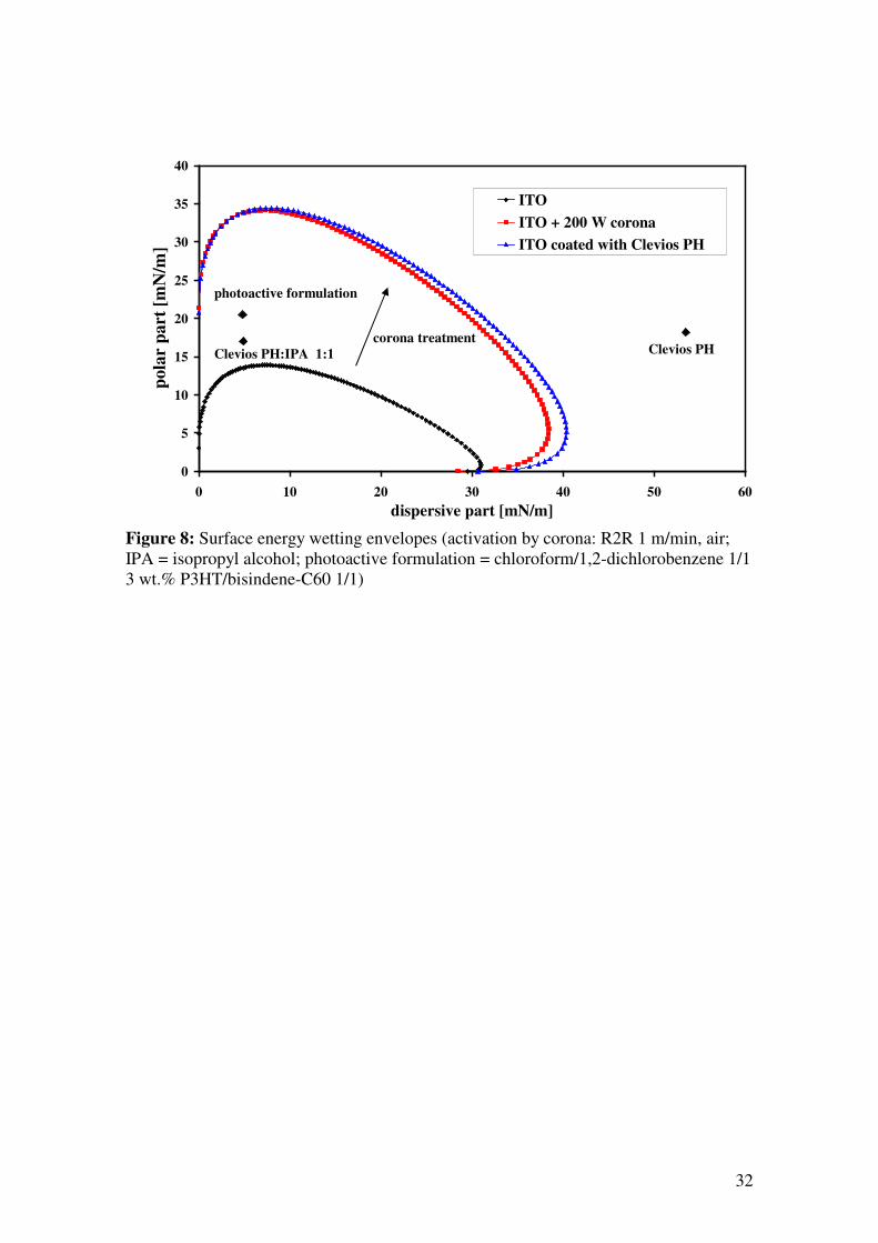
and makes sure that photoactive ink will give good wetting. The wetting envelopes of
the foils show that for instance isopropyl alcohol (IPA) addition to the PEDOT:PSS
causes a shift (71.7 mN/m to 21.9 mN/m) in the pretreated enhanced coating window of
the ITO-foil (Fig. 8). Viscosities and relation to shear stress of the PEDOT-PSS
derivatives were measured, too. The zero shear viscosity of PH is 64.0 mPas (50.8 mPas

11
at 40 s-1) and PH:IPA 1:1 39.0 mPas (33.1 mPas at 40.5 s-1); the viscosity is nearly
independent on shear stress while 4083 showed Newton-fluid behavior below 5 mPas.
With these preliminary investigations the R2R-coating trials started. However the first
results with pristine CHCl3 and CB were not fruitful. The film quality as well as the
efficiency of PSC were not good. Inspired by R2R-coating results for PCBM-systems
Krebs et al. describe[35] by taking mixtures consisting out of CHCl3 and DCB we tried
to transfer this on our system. In all mixtures with CHCl3:DCB the wetting was really
good, like expected from 3.1. The difficulties are to reach solidification (removing the
residual solvent) of the wet coated layer before mechanical stress from web transport let
the wet film drift. But also too fast drying is not wished, because of better film-
morphology with slower drying[69].
Experiments with small coating width (1.5 cm), applying CHCl3:DCB 1:2 in 4 wt.%
followed by manufacturing of PSC from samples out of it, show in principal good solar
cells with η larger 2 %. But the coating process is not stable enough. The concentration
is too high to stay continuously into the coating window to reach around 200 nm
thickness in dry layer. With the used concentration the coating tends to result in thicker
layers. Also the DCB content is still too high to avoid drifting of the wet film
completely. The value given in Table 1 (10) stands for only a few pieces. Much better
results were yielded with reduced concentration to 3 wt.% and 1:1 mixture of the
solvents. The surface energy of this ink was 25.3 mN/m (dispersive 20.5 mN/m; polar
4.8 mN/m) and lies within the wetting envelope of the PEDOT:PSS coated surface
excellently (Fig. 8). Using this ink for slot-die coating the obtained photoactive layer
was continuously homogeneous and touch-dry in time. The characteristic parameters of
the performance from PSC (Table 1, 11 and 12) out of these reels are representative for
the entire coating. Indeed η = 3.2 % is the best obtained value, but nearly all solar cells
12
manufactured from coated area of several meters give 2.5 up to more than 3 % light
power conversion efficiency. Up-scaling to 8 cm coating width was reached in PSC
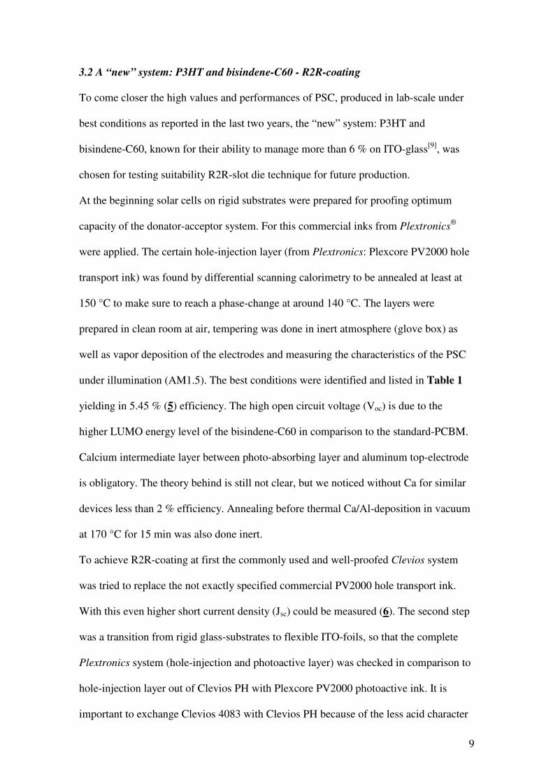
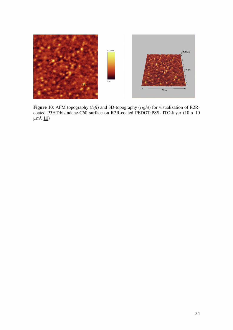
(reel) 11 (sample s. Fig. 9). The layer thickness of 260 nm was a bit too high; the
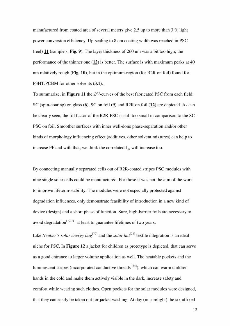
performance of the thinner one (12) is better. The surface is with maximum peaks at 40
nm relatively rough (Fig. 10), but in the optimum-region (for R2R on foil) found for
P3HT:PCBM for other solvents (3.1).
To summarize, in Figure 11 the J/V-curves of the best fabricated PSC from each field:
SC (spin-coating) on glass (6), SC on foil (9) and R2R on foil (12) are depicted. As can
be clearly seen, the fill factor of the R2R-PSC is still too small in comparison to the SC-
PSC on foil. Smoother surfaces with inner well-done phase-separation and/or other
kinds of morphology influencing effect (additives, other solvent mixtures) can help to
increase FF and with that, we think the correlated Jsc will increase too.
By connecting manually separated cells out of R2R-coated stripes PSC modules with
nine single solar cells could be manufactured. For those it was not the aim of the work
to improve lifeterm-stability. The modules were not especially protected against
degradation influences, only demonstrate feasibility of introduction in a new kind of
device (design) and a short phase of function. Sure, high-barrier foils are necessary to
avoid degradation[70,71] at least to guarantee lifetimes of two years.
Like Neuber´s solar energy bag[72] and the solar hat
[73] textile integration is an ideal
niche for PSC. In Figure 12 a jacket for children as prototype is depicted, that can serve
as a good entrance to larger volume application as well. The heatable pockets and the
luminescent stripes (incorporated conductive threads [74]), which can warm children
hands in the cold and make them actively visible in the dark, increase safety and
comfort while wearing such clothes. Open pockets for the solar modules were designed,
that they can easily be taken out for jacket washing. At day (in sun/light) the six affixed

13
solar cell modules can load the incorporated accumulator, powering the installed electric
functionalities.
But, neither investigation for finding best kind for connecting single PSC to modules
nor wearing tests of the textile were done. The showing of the special setup and its
visualization (marketing) was the aim. Nevertheless we see huge potential in laser-
ablation as patterning technique, what can also be done in R2R modus, and have gained
positive experiences in polymer field effect transistors production what now is going to
be transferred onto PSCs. [75]
“… cautious in predicting …” and without “… overhyping the technology …”, He and
Yu appropriate pointed out[76], the jacket as prototype shows an alternative PSC-product
niche, indeed with enlarging potential. Next to the look and the energy supply of the
PSCs the additional new functionalities in textiles are the main important features as
arguments for costumers not only children to acquire such products. With the growing
field of smart textiles polymer photovoltaics will have good chances to go alongside.
4. Conclusion
Starting with investigations and comparison of R2R-coating of standard system
P3HT:PCBM with different solvents it is to note that even the non-halogenated o-xy-
lene can be suitable for future large-scale application, showing good layer formation
and respectable efficiency of PSC prepared out of it. Pristine DCB cannot be applied at
the special used coating machine; the slow wetting complicates the drying. These results
were transferred onto the “new” photoactive system P3HT and bisindene-C60. On ITO-
PET 4.55 % light power conversion efficiency can be achieved with spin-coating and

14
even R2R production with 8 cm coating width and 1 m/min at air makes 3.2 % possible.
With these, in our opinion, good values for flexible and for R2R-produced PSCs
industrial applications move closer.
Manufactured PSC-modules could be introduced in a special functional jacket for
children open an alternative product niche. The safety benefit by wearing such textiles
goes beyond a simple outdoor recreational application.
Acknowledgements
Financial support of this work by the Thuringian Ministry (TMWAI 2004 WI0282), by
the BMBF (03X3518A “sonntex”) and by the BMWI (IW061016; 1136/03, VF071005,
IW082026, VF090063 and KA0406302DA7) is gratefully acknowledged. We wish to
thank Frank Apsel and his team from Maba GmbH Wolfen for technological support at
the LBA-200. Our special thanks go to Klaus Richter for the fruitful work regarding
jacket development.
References
[1] C.J. Brabec, S. Gowrisanker, J.J.M. Halls, D. Laird, S. Jia, S.P. Williams,
Polymer–fullerene bulk-heterojunction solar cells, Adv. Mater. 22 (2010) 3839-
3856.
[2] C. Deibel, V. Dyakonov, Polymer–fullerene bulk heterojunction solar cells, Rep.
Prog. Phys. 73 (2010) 096401 1-39.
[3] B.C. Thompson, P.P. Khlyabich, B. Burkhart, A.E. Aviles, A. Rudenko, G.V.
Shultz, C.F. Ng, L.B. Mangubat, Polymer-based solar cells: state-of-the-art
principles for the design of active layer components, Green 1 (2011) 29-54.

15
[4] Y. Liang, Z. Xu, J. Xia, S.-T. Tsai, Y. Wu, G. Li, C. Ray, L. Yu, For the bright
future - bulk heterojunction polymer solar cells with power conversion
efficiency of 7.4 %, Adv. Mater. 22 (2010) E135-E138.
[5] H.-Y. Chen, J. Hou, S. Zhang, Y. Liang, G. Yang, Y. Yang, L. Yu, Y. Wu, G.
Li, Polymer solar cells with enhanced open-circuit voltage and efficiency, Nat.
Photon 3 (2009) 649-653.
[6] D. Gendron, M. Leclerc, New conjugated polymers for plastic solar cells,
Energy Environ. Sci. 4 (2011) 1225-1237.
[7] Y.-J. Cheng, S.-H. Yang, C.-S. Hsu, Synthesis of conjugated polymers for
organic solar cell applications, Chem. Rev. 109 (2009) 5868-5923.
[8] D. Mi, J.-H. Kim, S.C. Yoon, C. Lee, J.-K. Lee, D.-H. Hwang, Synthesis and
characterization of a novel fullerene derivative containing carbazole group for
use in organic solar cells, Synth. Met. 161 (2011) 1330-1335.
[9] G. Zhao, Y. He, Y. Li, 6.5 % Efficiency of polymer solar cells based on poly(3-
hexylthiophene) and indene-C 60 bisadduct by device optimization, Adv. Mater.
22 (2010) 4355-4358.
[10] R.B. Ross, C.M. Cardona, D.M. Guldi, S.G. Sankaranarayanan, M.O. Reese, N.
Kopidakis, J. Peet, B. Walker, G.C. Bazan, E. Van Keuren, B.C. Holloway, M.
Drees, Endohedral fullerenes for organic photovoltaic devices, Nat. Mater. 8
(2009) 208-212.
[11] P.A. Troshin, H. Hoppe, J. Renz, M. Egginger, J.Y. Mayorova, A.E. Goryachev,
A.S. Peregudov, R.N. Lyubovskaya, G. Gobsch, N.S. Sariciftci, V.F. Razumov,
Material solubility-photovoltaic performance relationship in the design of novel
fullerene derivatives for bulk heterojunction solar cells, Adv. Funct. Mater. 19(5)
(2009) 779-788.

16
[12] L. Weber, S. Sensfuss, U. Ritter, P. Scharff, Preparation, characterization,
functionalization and application of dimeric fullerene oxides, Fullerenes,
Nanotubes and Carbon Nanostructures 17(2) (2009) 187-207.
[13] M.A. Green, K. Emery, Y. Hishikawa, W. Warta, E.D. Dunlop, Solar cell
efficiency tables (Version 38), Prog. Photovolt. Res. Appl. 19 (2011) 84-92.
[14] M.A. Green, K. Emery, Y. Hishikawa, W. Warta, E.D. Dunlop, Solar cell
efficiency tables (Version 39), Prog. Photovolt. Res. Appl. 20 (2012) 12-20.
[15] K. Colladet, S. Fourier, T.J. Cleij, L. Lutsen, J. Gelan, D. Vanderzande, L.H.
Nguyen, H. Neugebauer, S. Sariciftci, A. Aguirre, G. Janssen, E. Goovaerts,
Low band gap donor-acceptor conjugated polymers toward organic solar cells
applications, Macromolecules 40 (2007) 65-72.
[16] Y. Zou, D. Gendron, R. Badrou-Aich, A. Najari, Y. Tao, M. Leclerc, A high-
mobility low-bandgap poly(2,7-carbazole) derivative for photovoltaic
applications, Macromolecules 42 (2009) 2891-2894.
[17] O. Inganäs, F. Zhang, K. Tvingstedt, L.M. Andersson, S. Hellström, M.R.
Andersson, Polymer photovoltaics with alternating copolymer/fullerene blends
and novel device architectures, Adv. Mater. 22 (2010) E100-E116.
[18] S.H. Park, A. Roy, S. Beaupré, S. Cho, N. Coates, J.S. Moon, D. Moses, M.
Leclerc, K. Lee, A.J. Heeger, Bulk heterojunction solar cells with internal
quantum efficiency approaching 100 %, Nat. Photon. 3 (2009) 297-303.
[19] E. Bundgaard, O. Hagemann, M. Jørgensen, F.C. Krebs, Low bandgap polymers
for roll-to-roll coated organic photovoltaics – design, synthesis and
characterization, Green 1 (2011) 55-64.
[20] P. Zoombelt, M. Fonrodona, M.G.R. Turbiez, M.M. Wienk, R.A.J. Janssen,
Synthesis and photovoltaic performance of a series of small band gap polymers,
J. Mater Chem. 19 (2009) 5336-5342.

17
[21] J.-H. Tsai, C.-C. Chueh, M.-H. Lai, C.-F. Wang, W.-C. Chen, B.-T. Ko, C. Ting,
Synthesis of new indolocarbazole-acceptor alternating conjugated copolymers
and their applications to thin film transistors and photovoltaic cells,
Macromolecules 42(6) (2009) 1897-1905.
[22] T. Aernouts, R. de Bettignies, E. Bundgaard, S. Cros, M. Firon, M. Jørgensen,
E.A. Katz, F.C. Krebs, K. Norrman, Polymer Photovoltaics - A practical
approach, F.C. Krebs (Ed.) SPIE Press Bellingham Washington (USA) 2008.
[23] F.C. Krebs, H. Spanggard, T. Kiær, M. Niancardo, J. Alsstrup, Large area plastic
solar cells, Mater. Sci. En. B 138 (2007) 106-111.
[24] S. Sensfuss, L. Blankenburg, H. Schache, S. Shokhovets, T. Erb, A. Konkin, A.
Herasimovich, S. Scheinert, M. Shahid, S. Sell, E. Klemm, Thienopyrazine-
based low-bandgap polymers for flexible polymer solar cells, Eur. Phys. J. Appl.
Phys. 51 (2010) 33204.
[25] G. Dennler, C. Lungenschmied, H. Neugebauer, N.S. Sariciftci, M. Latrèche, G.
Czeremuszkin, M.R. Wertheimer, A new encapsulation solution for flexible
organic solar cells, Thin Solid Films 511-512 (2006) 349-353.
[26] K.-H. Tsai, J.-S. Huang, M.Y. Liu, C.-H. Chao, C.-Y. Lee, S.-C. Hung, C.-F.
Lin, High efficiency flexible polymer solar cells based on PET substrates with a
nonannealing active layer, J. Electrochem. Soc. 156(10) (2009) B1188-B1191.
[27] Y.-S. Hsiao, C.-P. Chen, C.-H. Chao, W.-T. Whang, All-solution-processed
inverted polymer solar cells on granular surface-nickelized polyimide, Org.
Electron. 10(4) (2009) 551-561.
[28] S. Choi, W.J. Potscavage, Jr., B. Kippelen, ITO-free large-area organic solar
cells, Opt. Express 18(103) (2010) A458-A466.

18
[29] Y.S. Kim, S.B. Oh, J.H. Park, M.S. Cho, Y. Lee, Highly conductive
PEDOT/silicate hybrid anode for ITO-free polymer solar cells, Sol. Energy
Mater. Sol. Cells 94 (2010) 471-477.
[30] F. Louwet (Agfa Orgacon), Recent development in ORGACON formulations
and ink for printable electrodes, Printed Electronics Europe (2010) Dresden
(Germany).
[31] C.-H. Liu, X. Yu, Silver nanowire-based transparent, flexible, and conductive
thin film, Nanoscale Res. Lett. 6:75 (2011) 1-8.
[32] A.J. Medford, M.R. Lilliedal, M. Jørgensen, D. Aarø, H. Pakalski, J. Fyenbo,
F.C. Krebs, Grid-connected polymer solar panels: initial considerations of cost,
lifetime, and practicality, Opt. Express 18(103) (2010) A272-A285.
[33] H. Zervos, Barrier films for flexible electronics: needs players & opportunities
2010-2020, http://www.salisonline.org/Reports/id-techex/, April 2011.
[34] http://www.nanomarkets.net/index.php/news/article/market_for_opv_dsc_
substrate_ and_encapsulation_materials_to_reach_1.3_billion_by_2017/.
[35] F.C. Krebs, S.A. Gevorgyan, J. Alstrup, A roll-to-roll process to flexible
polymer solar cells: model studies, manufacture and operational stability studies,
J. Mater. Chem. 19 (2009) 5442-5451.
[36] L. Blankenburg, K. Schultheis, H. Schache, S. Sensfuss, M. Schrödner, Reel-to-
reel wet coating as an efficient up-scaling technique for the production of bulk-
heterojunction polymer solar cells, Sol. Energy Mater. Sol. Cells 93 (2009) 476-
483.
[37] F.C. Krebs, Fabrication and processing of polymer solar cells: A review of
printing and coating techniques, Sol. Energy Mater. Sol. Cells 93 (2009) 394-
412.
19
[38] C.J. Brabec, J.R. Durrant, Theme article - Solution-processed organic solar cells,
MRS Bull. 33 (2008) 670-675.
[39] F.C. Krebs, Polymer solar cell modules prepared using roll-to-roll methods:
Knife-over-edge coating, slot-die coating and screen printing, Sol. Energy
Mater. Sol. Cells 93 (2009) 465-475.
[40] J. Kroon, W. Verhees, S. Veenstra, R. Andriessen, N.Grossiord, Y. Galagan,
Highly flexible printed ITO-free organic photovoltaics, 4th Int. Symp. Flex. Org.
Electron. 101 (2011) Thessaloniki (Greece).
[41] B. Zimmermann, H.-F. Schleiermacher, M. Niggemann, U.Würfel, ITO-free
flexible inverted organic solar cell modules with high fill factor prepared by slot
die coating, Sol. Energy Mater. Sol. Cells 95 (2011) 1587-1589.
[42] S.-S. Kim, S.-I. Na, S.-J. Kang, D.-Y. Kim, Annealing-free fabrication of
P3HT:PCBM solar cells via simple brush painting, Sol. Energy Mater. Sol. Cells
94 (2010) 171-175.
[43] M.M. Voigt, R.C.I. Mackenzie, C.P. Yau, P. Atienzar, J. Dane, P.E. Keivanidis,
D.D.C. Bradley, J. Nelson, Gravure printing for three subsequent solar cell
layers of inverted structures on flexible substrates, Sol. Energy Mater. Sol. Cells
95 (2011) 731-734.
[44] P. Kopola, T. Aernouts, S. Guillerez, H. Jin, M. Tuomikoski, A. Maaninen, J.
Hast, High efficient plastic solar cells fabricated with a high-throughput gravure
printing method, Sol. Energy Mater. Sol. Cells 94 (2010) 1673-1680.
[45] F. Durst, H.-G. Wagner, Slot Coating, in: Liquid film coating, Ed.: S.F. Kistler,
P.M. Schweizer, Chapman & Hall London (1997) 401-426.
[46] P.M. Schweizer, Verfahren zur gleichzeitigen Mehrfachbeschichtung, in:
Proceedings of Fundamentals and Methods in Coating, LSTM Erlangen 2005.

20
[47] H.G. Lippert, Slot die coating for low viscosity fluids, in: Coating Technology
Handbook, Ed.: A.A. Tracton, Taylor & Francis CRC Boca Raton (2006) 19 1-
15.
[48] G. Yu, A.J. Heeger, Charge separation and photovoltaic conversion in polymer
composites with internal donor/acceptor heterojunctions, J. Appl. Phys. 78
(1995) 4510-4515.
[49] G. Yu, J. Gao, J.C. Hummelen, F. Wudl, A.J. Heeger, Polymer photovoltaic
cells: Enhanced efficiencies via a network of internal donor-acceptor
heterojunctions, Science 270 (1995) 1789-1791.
[50] J.J.M. Halls, C.A. Walsh, N.C. Greenham, E.A. Marseglia, R.H. Friend, S.C.
Moratti, A.B. Holmes, Efficient photodiodes from interpenetrating polymer
networks, Nature 376 (1995) 498-500.
[51] S. van Bavel, E. Sourty, G. de With, S. Veenstra, J. Loos, Three-dimensional
nanoscale organization of polymer solar cells, J. Mater. Chem. 19 (2009) 5388-
5393.
[52] H. Hoppe, N.S. Sariciftci, Nanostructure and morphology engineering in
polymer solar cells, in: Nanostructured materials for solar energy conversion,
Ed.: T. Soga, Elsevier Amsterdam (2006) 277-318.
[53] G.D. Dennler, M.C. Scharber, C.J. Brabec, Polymer-fullerene bulk-
heterojunction solar cells, Adv. Mater. 21 (2009) 1323-1338.
[54] B. Schmidt-Hansberg, M. Sanyal, N. Grossiord, Y. Galagan, M. Baunach,
M.F.G. Klein, A. Colsmann, P. Scharfer, U. Lemmer, H. Dosch, J. Michels, E.
Barrena, W. Schabel, Investigation of non-halogenated solvent mixtures for high
throughput fabrication of polymer-fullerene solar cells, Sol. Energy Mater. Sol.
Cells 96 (2012) 195-201.
21
[55] Y. Galagan, I.G. de Vries, A.P. Langen, R. Andriessen, W.J.H. Verhees, S.C.
Veenstra, J.M. Kroon, Technology development for roll-to-roll production of
organic photovoltaics, Chem. Engin. Process.: Process Intensification 50(5-6)
(2011) 454-461.
[56] Y. He, H.-Y. Chen, J. Hou, Y. Li, Indene-C60 bisadduct: A new acceptor for
high-performance polymer solar cells, J. Am. Chem. Soc. 132 (2010) 1377-
1382.
[57] F. Apsel, Funktionalisierung von Oberflächen mittels Beschichtung aus dem
fluiden Zustand, Mat.-wiss. u. Werkstofftech. 32 (2001) 795-799.
[58] B. Park, M-y. Han, Photovoltaic characteristics of polymer solar cells fabricated
by pre-metered coating process, Opt. Exp. 17(16) (2009) 13830-13840.
[59] V. Dyakonov, Mechanisms controlling the efficiency of polymer solar cells,
Appl. Phys. A 79 (2004) 21-25.
[60] S. Bertho, W. D. Oosterbaan, V. Vrindts, J. D´Haen, T.J. Cleij, L. Lutsen, J.
Manca, D. Vanderzand, Controlling the morphology of nanofiber-P3HT:PCBM
blends for organic bulk heterojunction solar cells, Org. Electron. 10 (2009)
1248-1251.
[61] P. Schilinsky, C. Waldauf, C.J. Brabec, Performance analysis of printed bulk
heterojunction solar cells, Adv. Funct. Mater. 16 (2006) 1669-1672.
[62] W.Y. Huang, C.C. Lee, T.L. Hsieh, The role of conformational transitions on the
performance of poly(3hexylthiophene)/fullerene solar cells, Sol. Energy Mater.
Sol. Cells 93 (2009) 382-386.
[63] B. Zimmermann, U. Würfel, M. Niggemann, Longterm stability of efficient
inverted P3HT:PCBM solar cells, Sol. Energy Mater. Sol. Cells 93(4) (2009)
491-496.

22
[64] C.N. Hoth, S.A. Choulis, P. Schilinsky, C.J. Brabec, High photovoltaic
performance of inkjet printed polymer:fullerene blends, Adv. Mater. 19 (2007)
3973-3978.
[65] H.S. Kheshgi, The fate of thin liquid films after coating, in: Liquid Film Coating,
Ed.: S.F. Kistler, P.M. Schweizer, Chapman & Hall London (1997) 184-205.
[66] J. Zhao, A. Swinnen, G. Van Assche, J. Manca, D. Vanderzande, B. Van Mele,
Phase diagram of P3HT/PCBM blends and its implication for the stability of
morphology, J. Phys. Chem. B 113 (2009) 1587-1591.
[67] M.-Y. Chiu, U-S. Jeng, M.-S. Su, K.-H. Wie, Morphologies of self-organizing
regioregular conjugated polymer/fullerene aggregates in thin film solar cells,
Macromolecules 43 (2010) 428-432.
[68] A. Ppivrikas, N.S. Sariciftci, G. Juska, R. Österbacka, A review of charge
transport and recombination in polymer/fullerene organic solar cells, Prog.
Photovolt.: Res. Appl. 15 (2007) 677-696.
[69] M.T. Dang, G. Wantz, H. Bejbouji, M. Urien, O.J. Dautel, L. Vignau, L. Hirsch,
Polymeric solar cells based on P3HT:PCBM: Role of the casting solvent, Sol.
Energy Mater. Sol. Cells 95 (2011) 3408-3418.
[70] M. Jørgensen, K. Norrman, F.C. Krebs, Stability/degradation of polymer solar
cells, Sol. Energy Mater. Sol. Cells 92 (2008) 686-714.
[71] S. Cros, R. de Bettignies, S. Berson, S. Bailly, P. Maisse, N. Lemaitre, S.
Guillerez, Definition of encapsulation barrier requirements: A method applied to
organic solar cells, Sol. Energy Mater. Sol. Cells 95 (2011) S65-S69.
[72] http://www.energy-sunbags.de.
[73] F.C. Krebs, M. Jørgensen, K. Norrman, O. Hagemann, J. Alstrup, T.D. Nielsen,
J. Fyenbo, K. Larsen, J. Kristensen, A complete process for production of
23
flexible large area polymer solar cells entirely using screen printing - first public
demonstration, Sol. Energy Mater. Sol. Cells 93(4) (2009) 422-441.
[74] patent WO002004074401A1,Textile surface structure comprising an
arrangement of a plurality of conductive threads or threads exhibiting conductive
properties and method for the production thereof.
[75] I. Stohn, Rolle-zu-Rolle Laserstrukturierung zur Generierung polymerbasierter
Transistoren und Solarzellen, 6th Thüringer Grenz- und Oberflächentage (2010)
Jena (Germany).
[76] F. He, L. Yu, How far can polymer solar cells go? In need of a synergistic
approach, J. Phys. Chem. Lett. 2 (2011) 3102-3113.

24
Figure 1: Schematic illustration of R2R-coating
Figure 2: Slot die coating of P3HT:PCBM from o-xylene: 1 m/min, 5 cm (1)
Figure 3: R2R-coated PET-ITO-reels and sample stripes: left to right – PEDOT:PSS (Clevios PH) and 3, 2, 4, 1 and 1 trimmed width
Figure 4: UV/Vis transmission curves of R2R-made PSC 1-4 (Table 1, without top-electrodes) in relation to the pristine ITO-foil and coated with hole-injection layer (Clevios PH); inset: UV/Vis transmission curves before and after 5 min 100 °C (inert) Figure 5: J/V characteristics of best flexible solar cells PET/ITO/PEDOT:PSS(2 m/min R2R)/P3HT:PCBM(1 m/min R2R)/Al out of Table 1: blue rhombs - 4, green dotted - 1, red triangles - 3 and dark red squares - 2 Figure 6: AFM topography (left) and phase (right) of R2R-coated P3HT:PCBM on R2R-coated PEDOT:PSS layer (1-4 from Table 1, 10 x 10 µm²) Figure 7: Averaged conversion efficiencies (ηav) of spin-coated PSCs on foil depending on the annealing temperature: black rhombs – prepared similar to 8 (Tab. 1); red
squares - prepared similar to 8 (Tab. 1) with thinner photoactive layer (440 rpm instead of 400 rpm) Figure 8: Surface energy wetting envelopes (activation by corona: R2R 1 m/min, air; IPA = isopropyl alcohol; photoactive formulation = chloroform/1,2-dichlorobenzene 1/1 3 wt.% P3HT/bisindene-C60 1/1) Figure 9: Sample of 11 (Table 1), cutting for subsequent PSC and module manufacturing
Figure 10: AFM topography (left) and 3D-topography (right) for visualization of R2R-coated P3HT:bisindene-C60 surfaces on R2R-coated PEDOT:PSS- ITO-layer (10 x 10 µm², 11) Figure 11: J/V characteristics of best flexible solar cells PET/ITO/PEDOT:PSS/
P3HT:bisindene-C60/Ca/Al out of Table 1: red dotted – photoactive layer - 400 rpm/5 min spin-coating (9); blue squares - PEDOT:PSS -R2R (2 m/min) and photoactive layer R2R ( 1m/min) (12) in comparison to similar setup on ITO-glass (black rhombs, 6) Figure 12: left above: PSC-module, fabricated out of R2R-coated samples, separated by laser ablation (KrF-excimer 248 nm) and connected by Al-evaporation and textile integration (by Richter+Partner, Weimar) - right and left below – PSC as energy provider for LED-stripes and warming pockets in a jacket for children Table 1: Summary of experimental parameters for PSCs: different coating methods and variation in materials/compositions

25
Figure 1: Schematic illustration of R2R-coating
TCO-foil (ITO)
hole injection layer
photoactive layer
„reel–to–reel (R2R)“
slot-die-coatingn
S
(CH2)5CH3
+
26
Figure 2: Slot die coating of P3HT:PCBM from o-xylene: 1 m/min, 5 cm (1)

27
Figure 3: R2R-coated PET-ITO-reels and sample stripes: left to right – PEDOT:PSS (Clevios PH) and 3, 2, 4, 1 and 1 trimmed width

28
Figure 4: UV/Vis transmission curves of R2R-made PSC 1-4 (Table 1, without top-electrodes) in relation to the pristine ITO-foil and coated with hole-injection layer (Clevios PH); inset: UV/Vis transmission curves before and after 5 min 100 °C (inert)
0
20
40
60
80
100
200 300 400 500 600 700 800 900 1000
wavelength [nm]
tra
nsm
issi
on
[%
]
CBDCB + IRDCBXyPET-ITO PET-ITO-PH
30
40
50
60
70
400 450 500 550 600 650
wavelength [nm]
tra
nsm
issi
on
[%
]
CB temperedDCB temperedXy temperedCBXyDCB
increasing
absorption

29
Figure 5: J/V characteristics of best flexible solar cells PET/ITO/PEDOT:PSS(2 m/min R2R)/P3HT:PCBM(1 m/min R2R)/Al out of Table 1: blue rhombs - 4, green dotted - 1, red triangles - 3 and dark red squares - 2
-30
0
30
60
90
120
150
-2.0 -1.5 -1.0 -0.5 0.0 0.5 1.0 1.5 2.0
voltage [V]
curr
ent
den
sity
[m
A/c
m2]
-6
-5
-4
-3
-2
-1
0
1
2
3
4
0.0 0.1 0.2 0.3 0.4 0.5 0.6
voltage [V]
curr
ent
den
sity
[m
A/c
m2]
chlorobenzene
xylene
1,2-dichlorobenzene without IR
1,2-dichlorobenzene with IR

30
CB
Xy
DCB without IR drying
DCB with IR drying
Figure 6: AFM topography (left) and phase (right) of R2R-coated P3HT:PCBM on R2R-coated PEDOT:PSS layer (1-4 from Table 1, 10 x 10 µm²)

31
Figure 7: Averaged conversion efficiencies (ηav) of spin-coated PSC on foil depending on the annealing temperature: black rhombs – prepared similar to 8 (Tab. 1); red
squares - prepared similar to 8 (Tab. 1) with thinner photoactive layer (440 rpm instead of 400 rpm)
3.9
4.0
4.1
4.2
4.3
4.4
4.5
145 150 155 160 165 170 175
annealing temperature [°C]
ηη ηηa
v [
%]
400 rpm
440 rpm
32
Figure 8: Surface energy wetting envelopes (activation by corona: R2R 1 m/min, air; IPA = isopropyl alcohol; photoactive formulation = chloroform/1,2-dichlorobenzene 1/1 3 wt.% P3HT/bisindene-C60 1/1)
0
5
10
15
20
25
30
35
40
0 10 20 30 40 50 60
dispersive part [mN/m]
pola
r p
art
[m
N/m
]
ITO
ITO + 200 W corona
ITO coated with Clevios PH
corona treatmentClevios PHClevios PH:IPA 1:1
photoactive formulation

33
Figure 9: Sample of 11 (Table 1), cutting for subsequent PSC and module manufacturing
34
Figure 10: AFM topography (left) and 3D-topography (right) for visualization of R2R-coated P3HT:bisindene-C60 surface on R2R-coated PEDOT:PSS- ITO-layer (10 x 10 µm², 11)

35
Figure 11: J/V characteristics of best flexible solar cells PET/ITO/PEDOT:PSS/
P3HT:bisindene-C60/Ca/Al out of Table 1: red dotted – photoactive layer - 400 rpm/5 min spin-coating (9); blue squares - PEDOT:PSS -R2R (2 m/min) and photoactive layer R2R (1m/min) (12) in comparison to similar setup on ITO-glass (black rhombs, 6)
-11.0
-8.5
-6.0
-3.5
-1.0
1.5
4.0
6.5
9.0
0 0.2 0.4 0.6 0.8
voltage [V]
curr
ent
den
sity
[m
A/c
m2]
spincoating glass
spincoating foil
R2R-coating foil

36
Figure 12: left above: PSC-module, fabricated out of R2R-coated samples, separated by laser ablation (KrF-excimer 248 nm) and connected by Al-evaporation and textile integration (by Richter+Partner GmbH; Weimar) - right and left below – PSC as energy provider for LED-stripes and warming pockets in a jacket for children
LED-stripe
heatable pocket
PSC-modules

37
Table 1: Summary of experimental parameters for PSCs: different coating methods and variation in materials/compositions PSC ITO hole-injection layer photoactive layer ηηηηmax
f)
on mat.a)
coat.b)
drying mat.c)
solvent d)
coat. b)
drying Td
e)
[nm] (Voc;Jsc;FF)
1 foil Clevios PH:IPA
R2R 2 m/min,
5 cm
R2R 7 min 90 °C
P3HT: PCBM 1:0.8
1.2 wt.% Xy
R2R 1 m/min,
5 cm
R2R RT
108 1.17 %
(587; 3.94; 0.50)
2 foil Clevios PH:IPA
R2R 2 m/min,
5 cm
R2R 7 min 90 °C
P3HT: PCBM 1:0.8
1.2 wt.% DCB
R2R 1 m/min,
5 cm
R2R + 200 W
IR 108
1.02 %
(561; 5.13; 0.35)
3 foil Clevios PH:IPA
R2R 2 m/min,
5 cm
R2R 7 min 90 °C
P3HT: PCBM 1:0.8
1.2 wt.% DCB
R2R 1 m/min,
5 cm
R2R RT
108 1.26 %
(526; 4.74; 0.51)
4 foil Clevios PH:IPA
R2R 2 m/min,
5 cm
R2R 7 min 90 °C
P3HT: PCBM 1:0.8
1.2 wt.% CB
R2R 1 m/min,
5 cm
R2R RT
108 1.37 %
(601; 4.81; 0.47)
5 glass hole
transport inkg)
SC 1000 rpm
30 min 150 °C
air
PV 2000g)
2.0 wt.% DCB
SC 400 rpm 4.5 min
RT - 5.45 %
(831; 9.75; 0.67)
6 glass Clevios
4083
SC 1200 rpm
5 min 150 °C
air
PV 2000g)
2.0 wt.% DCB
SC 400 rpm
6 min RT -
5.80 % (823; 10.3; 0.68)
7 glass Clevios
4083
SC 1200 rpm
5 min 150 °C
air
P3HT: BIC60 1:0.8
1.8 wt.% DCB
SC 400 rpm
6 min RT -
4.93 %
(832; 9.26; 0.64)
8 foil hole
transport inkg)
SC 1000 rpm
15 min 150 °C
air
PV 2000g)
2.0 wt.% DCB
SC 400 rpm
6 min RT -
4.55 %
(836; 8.37; 0.65)
9 foil Clevios PH:IPA
SC 1200 rpm
10 min 120 °C
air
PV 2000g)
2.0 wt.% DCB
SC 400 rpm
6 min RT -
4.55 % (804; 8.56; 0.66)
10 foil Clevios PH:IPA
R2R 2 m/min,
4 cm
R2R 7 min 90 °C
P3HT: BIC60 1:0.8
4 wt.% DCB: CHCl3
2:1
R2R 1 m/min, 1.5 cm
R2R RT
187 2.82 %
(805; 6.47; 0.54)
11 foil Clevios PH:IPA
R2R 2 m/min,
7 cm
R2R 7 min 90 °C
P3HT: BIC60 1:0.8
3 wt.% DCB: CHCl3
1:1
R2R 1 m/min,
8 cm
R2R RT
206 (260)
2.71 % (796; 6,59; 0.52)
12 foil Clevios PH:IPA
R2R 2 m/min,
4 cm
R2R 7 min 90 °C
P3HT: BIC60 1:0.8
3 wt.% DCB: CHCl3
1:1
R2R 1 m/min,
5 cm
R2R RT
180 (218)
3.20 %
(800; 7.31; 0.55)
a) material: type of PEDOT:PSS-dispersion, Clevios PH:IPA (isopropyl alcohol) 1:1 (R2R, found thickness of dried film by ellipsometry ≈ 80-100 nm), 7:1 (SC, found thickness of dried film by ellipsometry ≈ 100 nm); b) kind of coating at air: R2R = reel-to-reel at LBA200, SC = spincoating in clean room with velocities and width; c) material: type and ratio of polymeric electron donator to fullerene-acceptor; d) concentration of photoactive material in solvent: Xy = o-xylene, DCB = o-dichlorobenzene, CB = chlorobenzene, DCB:CHCl3; 1:1 e) calculated thicknesses of dried R2R-made layers (Td), for calculation was used: Td = Q • c • ρliquid/(w • v • ρsolid • 100) assuming ρliquid = ρsolid = 1 g/cm³, Q = flow rate (ml/min), v = velocity (m/min), in brackets found by ellipsometry; f) best solar cell (Voc in mV, Jsc in mA/cm²), AM1.5, A = 0.25 cm², completion of cells on foil with PCBM (1-4) by evaporation of Al electrode and following annealing 5 min/100°C, completion of 5-12 by annealing 15 min/170°C and following evaporation of Ca (15 nm) and Al (50 nm), g) commercial product by Plextronics: Plexcore PV2000 hole transport ink and Plexcore PV2000 photoactive ink