Embed Size (px)
Citation preview
IAEA-TECDOC-806
Reference designfor a centralized
spent sealed sources facilityTechnical manual for the management of
low and intermediate level wastesgenerated at small nuclear research centres
and by radioisotope users in medicine, research and industry
INTERNATIONAL ATOMIC ENERGY AGENCY
The IAEA does not normally maintain stocks of reports in this series.However, microfiche copies of these reports can be obtained from
INIS ClearinghouseInternational Atomic Energy AgencyWagramerstrasse 5P.O. Box 100A-1400 Vienna, Austria
Orders should be accompanied by prepayment of Austrian Schillings 100,in the form of a cheque or in the form of IAEA microfiche service couponswhich may be ordered separately from the INIS Clearinghouse.
The originating Section of this publication in the IAEA was:
Waste Management SectionInternational Atomic Energy Agency
Wagramerstrasse 5P.O. Box 100
A-1400 Vienna, Austria
REFERENCE DESIGN FOR A CENTRALIZEDSPENT SEALED SOURCES FACILITY
IAEA, VIENNA, 1995IAEA-TECDOC-806
ISSN 1011-4289
© IAEA, 1995
Printed by the IAEA in AustriaJuly 1995
FOREWORD
The International Atomic Energy Agency has published Technical Reports Series and SafetySeries documents on radioactive waste management over nearly three decades. These documents haveserved Member States providing basic reference material and comprehensive surveys of 'state of theart' technologies applied to radioactive waste management.
The need for assistance in specific waste management problems facing many countries has beendemonstrated in IAEA activities including technical assistance projects and Waste ManagementAdvisory Programme (WAMAP) missions. Technical Reports Series and Safety Series documentsusually reflect:
technological solutions based on the experience and resources normally available in countriesmanaging nuclear fuel cycle wastes;
volumes and activities of radioactive wastes of orders of magnitude greater than those generatedin countries without nuclear power.
A series of technical documents has been undertaken especially to meet the needs of MemberStates for straightforward and low cost solutions to waste management problems. These documentswill:
give guidance on making maximum, practicable use of indigenous resources;
provide step-by-step procedures for effective application of technology;
recommend technological procedures which can be integrated into an overall national wastemanagement programme.
The series, entitled 'Technical Manuals for the Management of Low and Intermediate LevelWastes Generated at Small Nuclear Research Centres and by Radioisotope Users in Medicine,Research and Industry', will serve as reference material to experts on technical assistance missionsand provide 'direct know-how' for technical staff in Member States. Currently, the following manualshave been prepared:
Handling, Conditioning and Disposal of Spent Sealed Sources IAEA-TECDOC-548
Minimization and Segregation of Radioactive Wastes IAEA-TECDOC-652
Storage of Radioactive Wastes IAEA-TECDOC-653
Handling and Treatment of Radioactive Aqueous Wastes IAEA-TECDOC-654
Treatment and Conditioning of Radioactive Solid Wastes IAEA-TECDOC-655
Treatment and Conditioning of Radioactive Organic Liquids IAEA-TECDOC-656
Treatment and Conditioning of Spent Ion Exchange Resinsfrom Research Reactors, Precipitation Sludges and OtherRadioactive Concentrates IAEA-TECDOC-689
Handling, Treatment, Conditioning and Storage ofBiological Radioactive Wastes IAEA-TECDOC-775Reference Design for a Centralized Waste Processingand Storage Facility IAEA-TECDOC-776
The order of preparation of the manuals is based on the priority needs of Member States andit is recognized that additional areas of technical need may be identified as the programme isimplemented. In this regard the programme provides for sufficient flexibility, should other manualsor modifications prove necessary.
The objective of this report is to present a reference design of a Centralized Spent SealedSources Facility (SSS Facility) intended for countries generating small amounts of mainly sealedsources and other solid waste from nuclear applications in medicine, industry and research. The SSSFacility consists of a conditioning facility and an interim store building. It will be of special value forregulators and waste operators planning to establish or improve national waste management operatingcapabilities.
The report is based on a two volume SSS Facility reference design package prepared by AEATechnology, Harwell, UK, under a contract from the IAEA in 1992. In commissioning the referencedesign package, the IAEA defined several important requirements that the model design would haveto meet. Firstly, technological sophistication had to be kept to a minimum. The facility also had tobe robust and easy to operate without the need for extensive operational training of staff. Equipmentselected had to be simply designed and simple to operate and maintain. The costs of construction,operation and any expansion of the facility had to be kept low. The design also had to incorporateappropriate radiological protection arrangements in the interests of safety both of operators and of thegeneral public.
Work under the contract was co-ordinated by B.G. Pettersson, and the report was prepared byM.V. Wallin, both IAEA staff members in the Division of Nuclear Fuel Cycle and WasteManagement.
EDITORIAL NOTE
In preparing this publication for press, staff of the IAEA have made up the pages from theoriginal manuscripts). The views expressed do not necessarily reflect those of the governments of thenominating Member States or of the nominating organizations.
The use of particular designations of countries or territories does not imply any judgement bythe publisher, the IAEA, as to the legal status of such countries or territories, of their authorities andinstitutions or of the delimitation of their boundaries.
The mention of names of specific companies or products (whether or not indicated as registered)does not imply any intention to infringe proprietary rights, nor should it be construed as anendorsement or recommendation on the part of the IAEA.
CONTENTS
1. INTRODUCTION . . . . . . . . . . . . . . . . . . . . . . . . . . . . . . . . . . . . . . . . . . . . 7
2. OBJECTIVE AND SCOPE . . . . . . . . . . . . . . . . . . . . . . . . . . . . . . . . . . . . . . . 7
3. DESIGN CHARACTERISTICS . . . . . . . . . . . . . . . . . . . . . . . . . . . . . . . . . . . . 8
4. BASIC LAYOUT AND CONSTRUCTION . . . . . . . . . . . . . . . . . . . . . . . . . . . . . 9
4.1. Introduction . . . . . . . . . . . . . . . . . . . . . . . . . . . . . . . . . . . . . . . . . . . . . 94.2. Main building . . . . . . . . . . . . . . . . . . . . . . . . . . . . . . . . . . . . . . . . . . . . 94.3. Intérim store . . . . . . . . . . . . . . . . . . . . . . . . . . . . . . . . . . . . . . . . . . . . 14
5. FACILITY OPERATION . . . . . . . . . . . . . . . . . . . . . . . . . . . . . . . . . . . . . . . . 17
5.1. Receipt of source at facility . . . . . . . . . . . . . . . . . . . . . . . . . . . . . . . . . . . 175.2. Transfer of source to operational store . . . . . . . . . . . . . . . . . . . . . . . . . . . . 175.3. Conditioning of sources . . . . . . . . . . . . . . . . . . . . . . . . . . . . . . . . . . . . . 185.4. Transfer to interim store . . . . . . . . . . . . . . . . . . . . . . . . . . . . . . . . . . . . . 195.5. Interium store . . . . . . . . . . . . . . . . . . . . . . . . . . . . . . . . . . . . . . . . . . . . 195.6. Dealing with leaking/contaminated sources . . . . . . . . . . . . . . . . . . . . . . . . . 19
6. EQUIPMENT . . . . . . . . . . . . . . . . . . . . . . . . . . . . . . . . . . . . . . . . . . . . . . . 196.1. Introduction . . . . . . . . . . . . . . . . . . . . . . . . . . . . . . . . . . . . . . . . . . . . . 196.2. Source handling and inspection . . . . . . . . . . . . . . . . . . . . . . . . . . . . . . . . . 196.3. Radiation and contamination measurement and health physics . . . . . . . . . . . . . . 206.4. Drum handling and lifting . . . . . . . . . . . . . . . . . . . . . . . . . . . . . . . . . . . . 236.5. Cemented package preparation . . . . . . . . . . . . . . . . . . . . . . . . . . . . . . . . . 256.6. Tools . . . . . . . . . . . . . . . . . . . . . . . . . . . . . . . . . . . . . . . . . . . . . . . . . 256.7. Consumables . . . . . . . . . . . . . . . . . . . . . . . . . . . . . . . . . . . . . . . . . . . . 25
7. MANAGEMENT AND STAFFING . . . . . . . . . . . . . . . . . . . . . . . . . . . . . . . . . 28
7.1. General principles . . . . . . . . . . . . . . . . . . . . . . . . . . . . . . . . . . . . . . . . . 287.2. Key posts . . . . . . . . . . . . . . . . . . . . . . . . . . . . . . . . . . . . . . . . . . . . . . 29
8. QUALITY ASSURANCE . . . . . . . . . . . . . . . . . . . . . . . . . . . . . . . . . . . . . . . . 29
9. SAFETY CONSIDERATIONS . . . . . . . . . . . . . . . . . . . . . . . . . . . . . . . . . . . . . 30
10. COST ESTIMATE . . . . . . . . . . . . . . . . . . . . . . . . . . . . . . . . . . . . . . . . . . . . 31
REFERENCES . . . . . . . . . . . . . . . . . . . . . . . . . . . . . . . . . . . . . . . . . . . . . . . . . 32

1. INTRODUCTION
Proper management of spent sealed sources requires an established radioactive wastemanagement infrastructure and, in particular, a facility designed for the specific purpose ofconditioning and subsequent interim storage of spent sealed sources. Such a facility does not exist inmany developing countries, especially those where radionuclides are used in only a few hospitals orresearch institutes.
To assist Member States in establishing facilities in which the most frequently occurring spentsealed sources can be safely conditioned, the IAEA has financed the development of a generic designfor a Spent Sealed Sources Facility (SSS Facility). The purpose of this facility is twofold:
the conditioning of spent sealed sources by embedding in cement;
the interim storage of the resulting waste package for a period until a suitable repository isavailable for final disposal.
The complete report [1], which is available from the Waste Management Section of the IAEA,provides a description of the plant and the necessary equipment, and of the operations performedwithin the facility. A set of annexes to the complete report gives detailed information on the followingitems:
1. Layout and outline; construction details;2. Safety assessment;3. Operating procedures;4. Quality assurance;5. Equipment lists;6. Treatment of leaking or contaminated sources;7. Cost estimate details.
2. OBJECTIVE AND SCOPE
The purpose of this TECDOC is to provide enough general information about the functions andcapabilities of the SSS Facility to enable the reader to understand what the facility can do to contributetowards the management of spent sealed sources without providing all the technical and/or designinformation available. Sufficient information is provided to enable the reader to judge how and towhat extent such a facility can contribute to national radioactive waste management infrastructure.Once a decision is made to adopt the design and to construct the facility, additional detailed technicalinformation can be obtained from the complete report [1].
The SSS Facility is intended for conditioning and interim storage of spent sealed sources withan activity upper bound of about 10 TBq. The sources are expected to be mounted in housings orother suitable shielding. Special facilities for handling unshielded, high activity sources (hot cells) arenot included in the design. Arrangements for handling leaking sources are included as an option.
For situations where both liquid and solid radioactive waste is produced in small but significantquantities in a Member State, the IAEA has prepared a Reference Design of a Centralized WasteProcessing and Storage Facility [2].
Two separate buildings constitute the SSS Facility. The Main Building is designed to receiveand for the operational storage and conditioning of the spent sealed sources. This building also housessupport facilities such as change-room, sanitary rooms, radiation monitoring room, space for thestorage of raw materials and office space. The Interim Store building is designed for the long termstorage of conditioned spent sealed sources.
The design reconciles the potential that an existing building could be modified for operationalconditioning activities. Information is provided that could be used as a reference specification againstwhich the suitability of an existing building could be judged.
The reference design can be used by a Member State as a basis for the final design of an SSSFacility, adapted as necessary to accommodate local ground, geological and meteorological conditions.
3. DESIGN CHARACTERISTICS
The design of the SSS Facility incorporates appropriate features for safe handling, conditioningand storing of spent sealed sources. The waste packages produced can be safely stored for longperiods of time, awaiting eventual disposal in a licensed repository when that becomes available. Thegeneral design characteristics are described under specific headings as follows:Technology: Technology sophistication is kept at a minimum, and the only equipment selected
is such that has proved to be fully operational for the intended purpose.
Robustness: The facility is rugged, easy to operate without extensive training of operating staff,and has a high degree of accessibility.
Engineering: The facility equipment is easy to maintain, and the interim storage part of thefacility is easy to expand.
Flexibility: Operational use of certain functional capabilities of the facility is likely to beinfrequent. This pertains in particular to the handling of leaking radium sourcesand to the handling of consignments of spent sealed sources that do not fullycomply with the provision of the relevant transport regulations (e.g. due to damagein transit). The design incorporates features that provide the possibility ofestablishing temporary workplaces for these activities rather than permanentinstallations. This approach also applies to equipment maintenance work.
Economy: The costs of constructing, operating and expanding the facility have been kept aslow as reasonably possible.
Safety: Radiation protection and industrial safety aspects are appropriately considered forboth the plant operation staff and for the general public off-site.
Licensing: A generalized safety analysis report has been developed to demonstrate compliancewith the relevant IAEA Safety Standards and Safety Guides. It is to be noted thatall aspects of licensing the facility are the responsibility of the Member State.
In-drum cementation into 200 L steel drums is the basis for the process of conditioning spentsealed sources. The handling of waste packages and raw materials is provided for by using of forklifts capable of lifting up to 500 kg. The main building has several separate stores: receipt store,decay store, store for high activity sources and/or contaminated housings and operational store forsources to be conditioned. The separate interim store building has capacity for storing approximately100 steel drums arranged in groups to facilitate routine inspection and monitoring.
The design package includes detailed information on operating procedures and a wastemanagement related quality assurance model. Similarly, a generic safety assessment of the facility isincluded, together with an overview of the safety assessment methodology to be adopted inperforming a 'real' safety assessment.
As a design implementation option, equipment and procedures for handling leaking sources (inparticular radium), is included.
8
4. BASIC LAYOUT AND CONSTRUCTION
4.1. INTRODUCTION
Three different constructions for the SSS Facility are outlined, suited for three different typesof climate:
Warm, arid climate: In situ reinforced concrete framed building with walls and flat roof alsomade of concrete;
Warm, humid climate: In situ reinforced concrete framed building with concrete walls and pitchedroof to improve water run-off;
Cold climate: Steel framed, metal clad and thermally insulated building with pitched roof.
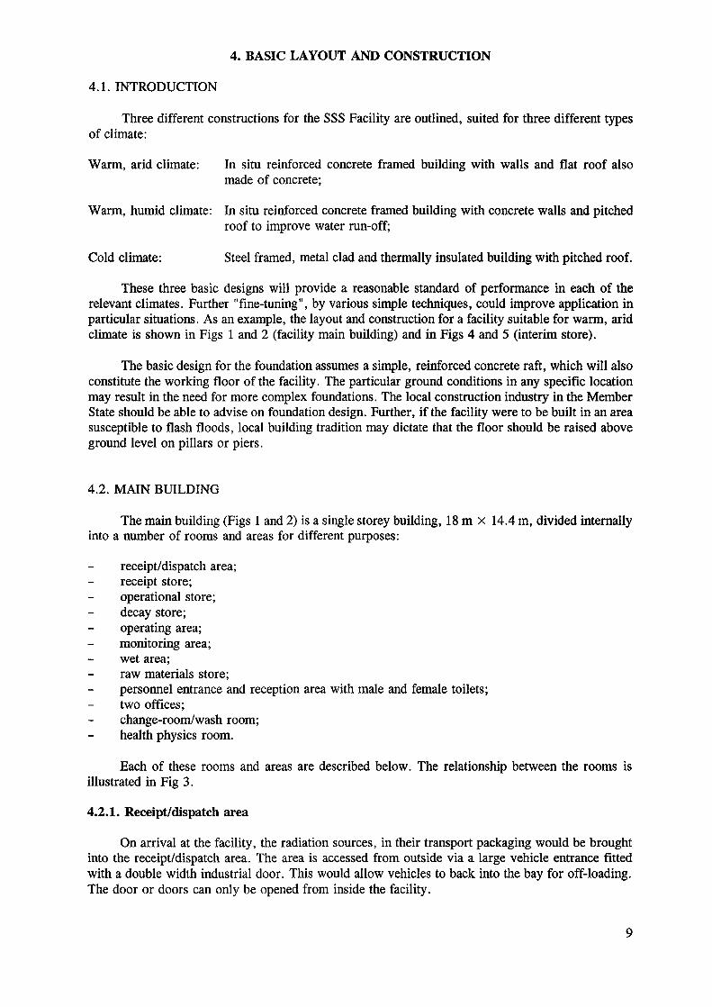
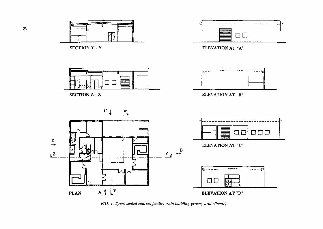
These three basic designs will provide a reasonable standard of performance in each of therelevant climates. Further "fine-tuning", by various simple techniques, could improve application inparticular situations. As an example, the layout and construction for a facility suitable for warm, aridclimate is shown in Figs 1 and 2 (facility main building) and in Figs 4 and 5 (interim store).
The basic design for the foundation assumes a simple, reinforced concrete raft, which will alsoconstitute the working floor of the facility. The particular ground conditions in any specific locationmay result in the need for more complex foundations. The local construction industry in the MemberState should be able to advise on foundation design. Further, if the facility were to be built in an areasusceptible to flash floods, local building tradition may dictate that the floor should be raised aboveground level on pillars or piers.
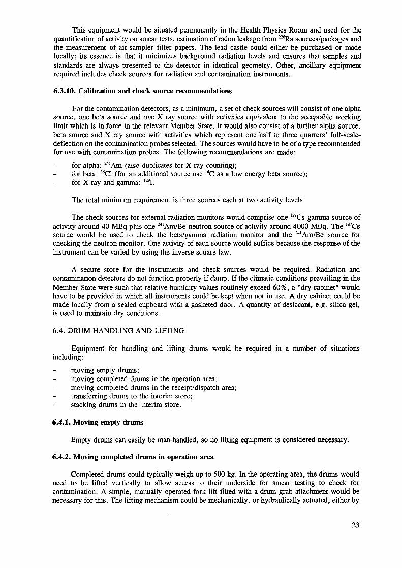
4.2. MAIN BUILDING
The main building (Figs 1 and 2) is a single storey building, 18 m x 14.4 m, divided internallyinto a number of rooms and areas for different purposes:
receipt/dispatch area;receipt store;operational store;decay store;operating area;monitoring area;wet area;raw materials store;personnel entrance and reception area with male and female toilets;two offices;change-room/wash room;health physics room.
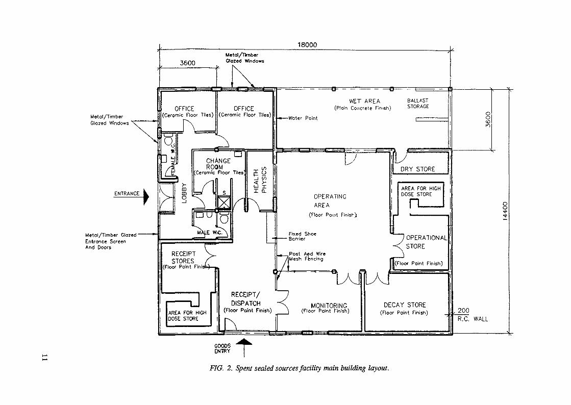
Each of these rooms and areas are described below. The relationship between the rooms isillustrated in Fig 3.
4.2.1. Receipt/dispatch area
On arrival at the facility, the radiation sources, in their transport packaging would be broughtinto the receipt/dispatch area. The area is accessed from outside via a large vehicle entrance fittedwith a double width industrial door. This would allow vehicles to back into the bay for off-loading.The door or doors can only be opened from inside the facility.
DD
SECTION Y - Y ELEVATION AT "A"
fi DD
SECTION Z - Z
D
ZB
PLAN
ELEVATION AT "B'
ELEVATION AT "C"
s— — — - —
DD ûN]
\/
\\\
1
—— —— - —— —— ID
ELEVATION AT "D"
FIG. 1. Spent sealed sources facility main building (warm, arid climate).
18000
Metol/TimberGlozed Windows '
ENTRANCE
Metal/Timber Glozed •Entrance ScreenAnd Doors
Metal/TimberGlozed Windows
OFFICE(Ceromic Floor Tiles)
OFFICE(Ceromic Floor Tiles)
CHANGEROOM
Ceromic Floor Tiles(/)
WET AREA(Ploin Concrete Finish)
-Woter Point
RECEIPT V_STORES f
(Floor Point Finish) ...
RECEIPT/DISPATCH
(Floor Point Finish)
Fixed Shoe• Borrier
„ ,POS< Atd Wir«/Mesh Fencing
OPERATINGAREA
(Floor Point Finish)
AREA FOR HIGHDOSE STORE
OPERATIONALSTORE
loor Point Finish)
AREA FOR HIGHDOSE STORE
MONITORING(Floor Point Finish)
DECAY STORE(Floor Point Finish) , 200
R.C. WALL
oo-t
FIG. 2. Spent sealed sources facility main building layout.
Clean area
Personnelentry/exit
t IEntrance
lobby
Changerooms
Officerooms
Sanltoryrooms
HealthPhysics
Receiptstore
n nReceipt/dispatch
area
Goods in/out
Dirty area
Materials in
Ballastarea
Drystore
A
VOperatingarea
A nOperational
store
Monitoringarea
— ->•
<3 ——
Decaystore
Personnel control atgated monitoring area
Personnel movement Goods movement
FIG. 3. Spent sealed sources facility main building. Rooms relationship diagram.
12
The receipt/dispatch area is an open area, 3.6 m X 5.4 m, illuminated by electric lighting. Thesmooth floor is painted with an easily decontaminated floor paint. The concrete walls and the ceilingare also painted. The wall to the operating area and monitoring area could be a wire mesh screen orother, simple partition.
4.2.2. Receipt store
The receipt store is a room, 3.6 m x 5.4 m, used to store all radiation sources within theirtransport packaging following receipt at the facility. Access to the store is via lockable, secure doubledoors. Shelving or racks within the store will be used for storage of most radiation sources. Largeand heavy sources can be stored on the floor. If particularly high dose rate packages are received,they can be stored in one corner of the room behind a simple shielding wall. This could be built fromconcrete blocks, or from poured concrete built at the same time as the facility.
The store has simple electric lighting. There are no windows because these could be both ashielding and a security weakness. The smooth floor is painted with an easily decontaminated floorpaint. The concrete walls and the ceiling are also painted.
4.2.3. Operational store
The operational store is similar in size and construction to the receipt store. The operationalstore is used to hold sources temporarily when their transport packaging has been removed, andbefore they are encapsulated in cement. Storage is, again, either on shelving or racks or on the floor.A simple shielding wall in one corner of the room provides additional shielding for high dose ratesources.
The store is accessed from the operating area via lockable, secure double doors. There are nowindows. The smooth floor is painted with an easily decontaminated floor paint. The concrete wallsand the ceiling are also painted.
4.2.4. Decay store
The decay store is also similar in size to the receipt store and operational store. It is includedin the design as a means of segregating and holding short-lived isotope sources. Typically, the periodof storage would be a maximum of one year, adequate for the decay of medical diagnosticradionuclides to below regulatory clearance levels.
The store is accessed from the operating area via lockable, secure double doors. There are nowindows. Storage of radiation sources will be on shelves or racks or on the floor.
Electric lighting is provided for illumination within the store. The smooth floor is painted withan easily decontaminated floor paint. The concrete walls and the ceiling are also painted.
4.2.5. Operating area and monitoring area
The operating area and the adjacent monitoring area are a large open area in the centre of thefacility where radiation sources are handled, monitored, unpacked from their transport packaging andeventually embedded in cement within 200 L drums.
Personnel access into the operating area is via the change-room and over the footwear-changebarrier. Access for bringing sources into the operating area is via lockable double doors between thereceipt/dispatch area and the monitoring area.
The monitoring area has a bench on which sources can be unpacked. A fume cupboard islocated in the operating area against the outside wall. The ventilation extract from the fume cupboardis passed through a duct in the outside wall.
13
The floor of the operating area and the monitoring area is painted with an easily decontaminatedfloor paint. The concrete walls and the ceiling are also painted.
4.2.6. Wet area
A wet area is incorporated adjacent to the operating area but essentially outside the mainbuilding although still covered by the roof of the building. This area is for the handling andpreparation of cement for use when encapsulating sources.
The preparation of cement will generate a certain amount of mess, with cement powder, sandand water spills. In addition, cement powder can easily become airborne, creating an unpleasant andpotentially harmful nuisance to personnel. Placing the cement handling area outside the buildingprovides good ventilation for cement powder handling, and avoids making a mess within the mainoperating area.
The floor of the wet area is sloped away from the access door into the operating area. Thisallows the floor to be washed down and easily drained when cleaning-up after preparing cement. Asmall bund at the doorway prevents any washdown water from flowing back into the operating area.A wire mesh fence around the outside of the wet area provides security and prevents unauthorizedpersonnel access to the facility. A lockable gate is incorporated within the wire mesh fence to enableaccess for the delivery of sand, cement and drums. The wet area is served by clean water supply forthe preparation of cement, and also for washdown. At one end of the wet area, small bunkers enablethe storage of sand and clean, empty drums. There is also a small dry store accessible from the wetarea. Here, bags of cement and plastic sheet are stored.
Access from the operating area to the wet area is via a lockable double width door.
The floor of the wet area is left to the natural finish. The concrete walls and the ceiling arepainted.
4.2.7. Other areas
Personnel access to the main building is via double doors, initially into a lobby area. This areahas male and female toilet facilities. Two offices are located at the end of a short corridor. Theseoffices would be the centre for the administration side of the SSS Facility operation. The lobby,female toilet and offices have outside windows for natural lighting.
The change-room/washroom is accessed from the lobby. This room has facilities for operators,e.g. lockers, wash basin, shower and hand-held personnel monitoring equipment.
Adjacent to the change-room is a small health physics room. This room would be used for thestorage, maintenance and calibration of health physics equipment. It could also be used as a clean,low background area for the counting of samples, e.g. contaminated swabs.
Personnel protective equipment, e.g. disposable coveralls, overshoes and gloves, would alsobe stored in the health physics room on shelves.
These rooms generally have painted concrete walls and ceilings, except for the change-room/washroom adjacent to the wash basin and shower and in the toilets, where the walls are tiledin ceramic. All rooms have ceramic tiled floors.
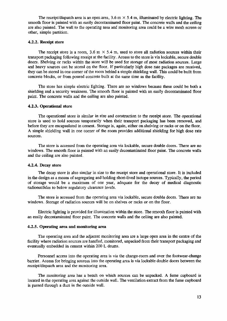
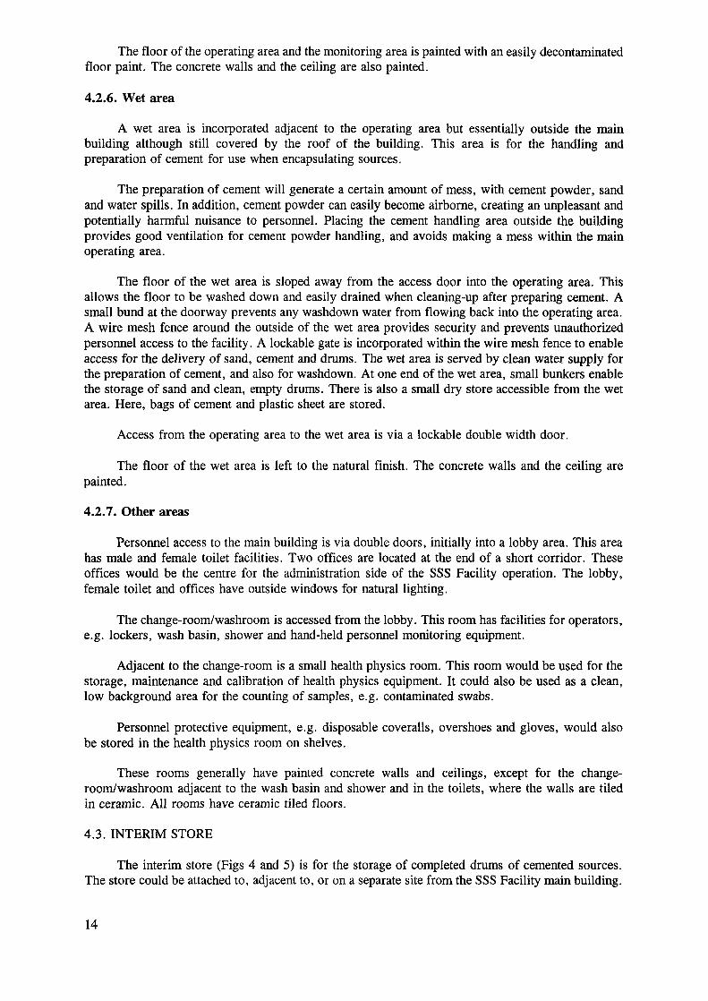
4.3. INTERIM STORE
The interim store (Figs 4 and 5) is for the storage of completed drums of cemented sources.The store could be attached to, adjacent to, or on a separate site from the SSS Facility main building.
14
SECTION Y - Y
PLANA
B
d
ELEVATION AT "AH A 11
ELEVATION AT "B"
FIG. 4. Spent sealed sources facility interim store (warm, arid climate).
Emergency Exil
S
STORE f(Floor Pai
—— J-
3600 [
BUILDING "^it Finish)
——— L ——————
/A
7200
\i
^200 g00o
/
\
\
F/G. 5. Spent sealed sources facility interim store layout.
16
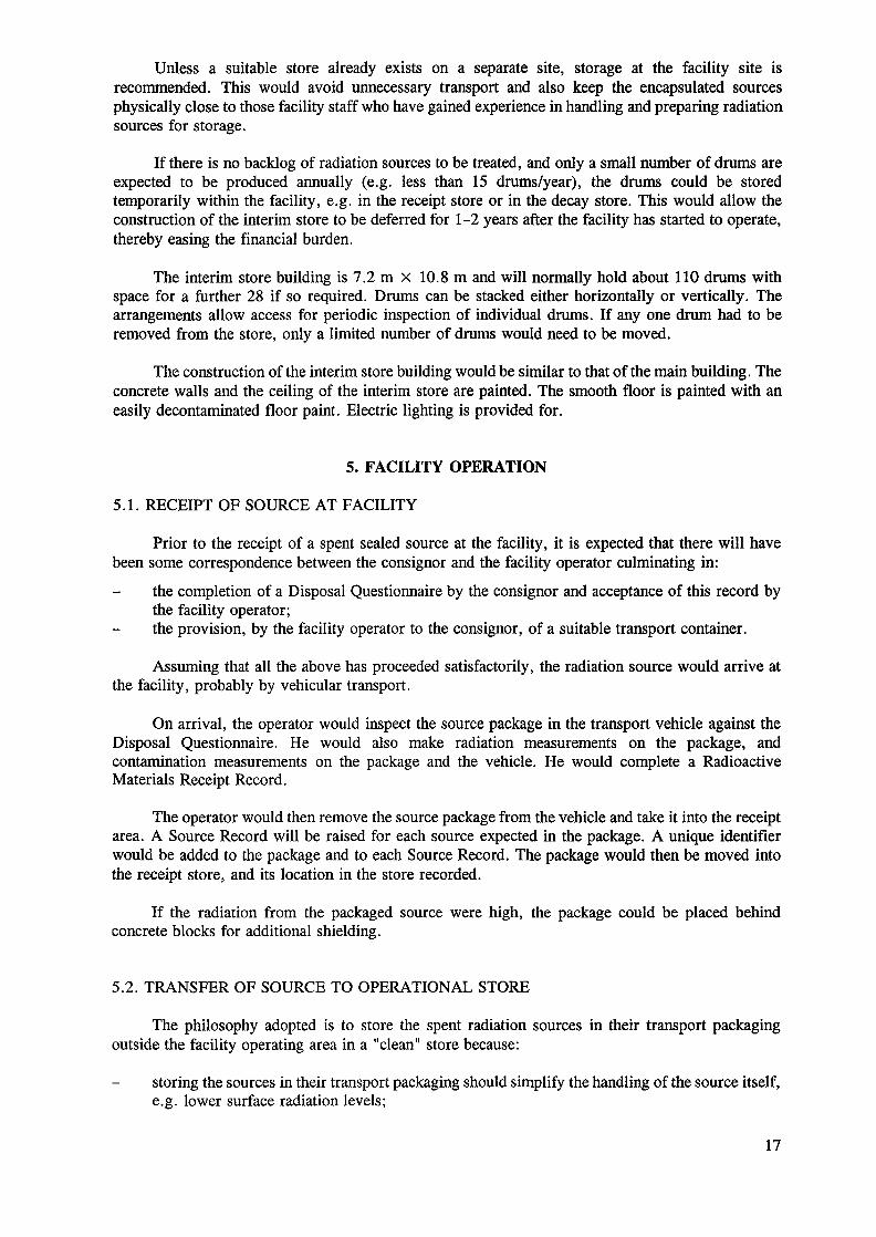
Unless a suitable store already exists on a separate site, storage at the facility site isrecommended. This would avoid unnecessary transport and also keep the encapsulated sourcesphysically close to those facility staff who have gained experience in handling and preparing radiationsources for storage.
If there is no backlog of radiation sources to be treated, and only a small number of drums areexpected to be produced annually (e.g. less than 15 drums/year), the drums could be storedtemporarily within the facility, e.g. in the receipt store or in the decay store. This would allow theconstruction of the interim store to be deferred for 1-2 years after the facility has started to operate,thereby easing the financial burden.
The interim store building is 7.2 m x 10.8 m and will normally hold about 110 drums withspace for a further 28 if so required. Drums can be stacked either horizontally or vertically. Thearrangements allow access for periodic inspection of individual drums. If any one drum had to beremoved from the store, only a limited number of drums would need to be moved.
The construction of the interim store building would be similar to that of the main building. Theconcrete walls and the ceiling of the interim store are painted. The smooth floor is painted with aneasily decontaminated floor paint. Electric lighting is provided for.
5. FACILITY OPERATION
5.1. RECEIPT OF SOURCE AT FACILITY
Prior to the receipt of a spent sealed source at the facility, it is expected that there will havebeen some correspondence between the consignor and the facility operator culminating in:
the completion of a Disposal Questionnaire by the consignor and acceptance of this record bythe facility operator;the provision, by the facility operator to the consignor, of a suitable transport container.
Assuming that all the above has proceeded satisfactorily, the radiation source would arrive atthe facility, probably by vehicular transport.
On arrival, the operator would inspect the source package in the transport vehicle against theDisposal Questionnaire. He would also make radiation measurements on the package, andcontamination measurements on the package and the vehicle. He would complete a RadioactiveMaterials Receipt Record.
The operator would then remove the source package from the vehicle and take it into the receiptarea. A Source Record will be raised for each source expected in the package. A unique identifierwould be added to the package and to each Source Record. The package would then be moved intothe receipt store, and its location in the store recorded.
If the radiation from the packaged source were high, the package could be placed behindconcrete blocks for additional shielding.
5.2. TRANSFER OF SOURCE TO OPERATIONAL STORE
The philosophy adopted is to store the spent radiation sources in their transport packagingoutside the facility operating area in a "clean" store because:
storing the sources in their transport packaging should simplify the handling of the source itself,e.g. lower surface radiation levels;
17
storing the packaged sources outside the operating area reduces the possibility of contaminationof the packaging. If the packaging has not been into the operating area it will make it easier todispose of or reuse it when the source is removed and without extensive monitoring.
In preparation for a campaign of cement encapsulation, a number of spent sources would betransferred from the receipt store to the operational store within the operating area.
For any one source the radiation and contamination levels on the package would be checked,and the package would be moved from the store, across the receipt/dispatch area into the monitoringarea. Here, the outer transport packaging would be removed to reveal the spent source in its holderor pot. The transport packaging would be monitored as it is removed allowing it to be disposed ofas inactive waste or re-used. The outer surfaces of the source in its holder or pot would also bemonitored before transferring it to the operational store.
If the radiation levels from the source are high, concrete shielding blocks may be positionedaround the source in the operational store.
The operator would update the Source Record at this point, transferring information from theDisposal Questionnaire and Radioactive Materials Receipt Record and adding the operational storagelocation. The Source Record and the source in its pot or holder would also be marked with the sourceidentifier. The record would then be returned to the file.
5.3. CONDITIONING OF SOURCES
Before a spent sealed source can be embedded in cement within a 200 L drum, the followingmaterial should be obtained:
200 L drum, free from rust spots or other defects, painted inside and outside, and marked witha unique identifier. Plastic sheet is wrapped around the drum and taped at the top to protect thedrum from cement splashes;cement powder and sand;supply of water;cement mixer, or shovel;steel reinforcement.
The cementation of sources would be carried out within the operating area. The preparation ofcement would be performed in the adjacent wet area.
The operator firstly prepares the drum by partly filling it with cement and inserting thereinforcement. After a short period to allow the cement to set, the source in its holder or appropriateshielding is placed in the drum, and more cement added. Several such items may be placed in onedrum. When the final item has been added, the drum is filled to the top with cement, and thenallowed to stand, typically for 16 hours to allow the cement to cure. After this time, any remainingbleed water is removed, and contamination checks are made. The drum is then lidded and moved tothe monitoring area where radiation level measurements are made.
A Drum Record is made for each drum, recording information on the sources within the drum,contamination and radiation levels and the drum weight. It is expected that several drums would beprepared in one campaign over a 2-3 day period.
Once a drum had been confirmed as free of contamination and provided with proper labelling,it would be moved into the receipt/dispatch area for temporary storage awaiting transfer to the interimstore.
18
5.4. TRANSFER TO INTERIM STORE
Completed drums would be transferred to interim store to await final disposal. The interim storemay be adjacent to or on the same site as the SSS Facility main building, or it may be on a distantsite requiring vehicular transport.
If on the same site, the drum would be transferred to the interim store using appropriatetransport equipment, e.g. a trolley or a fork lift.
5.5. INTERIM STORE
In the interim store, the drum would be placed in a specified location, and details of the drumand its position be added to the Store Record and to the Drum Record. Drums would be stackedwithin the store in rows. This arrangement would allow personnel access to any one drum allowingperiodic contamination checks, and also to monitor the general condition of the drum.
5.6. DEALING WITH LEAKING/CONTAMINATED SOURCES
The operators of the SSS Facility should treat every source as if it were a leaking source untilproven otherwise by smear testing. If a source were discovered to be leaking, either during unpackingor during routine inspection in the store, the health physicist would be consulted and it would thenbe moved to the fume cupboard. Temporary lead brick shielding would be erected around the sourceif necessary. A decision would then be made on the optimum method of re-encapsulation of the sourceto contain any contamination. Once the source has been re-encapsulated it may be returned to storage,or cemented in a drum as other sources.
6. EQUIPMENT
6.1. INTRODUCTION
A range of equipment and consumables would be required in performing the handling andencapsulation of spent sealed sources. Although a few specialist items of equipment would benecessary, the majority of equipment should be readily available in developing Member States of theIAEA. Such has been a design objective.
The equipment required in the facility is discussed below under the following subject headings:
source handling and inspection;radiation and contamination measurement/health physics;drum handling and lifting;cemented package preparation;tools;consumables.
In general, the descriptions simply highlight the features required for each piece of equipment.However, for specialist equipment, recommendations are made, based on extensive experience forspecific types or even specific items of equipment.
6.2. SOURCE HANDLING AND INSPECTION
6.2.1. Fume cupboard
If radium sources or leaking/contaminated sources are to be handled, a fume cupboard is asimple, safe and effective means of protecting the operator and preventing the spread of
19
contamination. A fume cupboard is a safety cabinet with an opening through which the operator cancarry out manipulation inside the cabinet and with air being continuously exhausted from the cabinetat sufficient rate to prevent the escape of airborne contamination generated within the cabinet.
The fume cupboard can be obtained from a number of manufacturers in different standard sizes.A one metre wide cabinet would be adequate for handling most sources. The cabinet should featurea crevice-free construction from stainless steel, finished with a highly resistant white stove enamel.It should be fitted with a high efficiency paniculate air (HEPA) filter with a penetration of less than0.005%. A pre-filter should be fitted to extend the life of the main filter. A fluorescent tube shouldbe fitted to provide adequate lighting levels for operation.
Temporary shielding in the form of lead bricks could be assembled inside the fume cupboardto reduce operator dose when handling high dose rate sources. This approach would minimize costand maximize the flexibility of providing safe working for operators.
6.2.2. Long reach tongs
In routine operation, radiation sources are handled in transport containers or in other shieldingwhich protects the operators from high radiation doses and the packages can be handled manually orusing a fork-lift. When, for specific reasons, the radiation sources themselves have to be handled, theoperator should be as far away as possible from the sources in order to minimize the dose. Simplelong-reach tongs (one and two metre length) should be used for the purpose of transferring sourcesfrom one location to another. In the fume cupboard where space is at a premium, maximumseparation of operator from sources can be achieved by the use of forceps or short tongs.
It must be recognized that handling work using tongs and forceps makes it possible to lift onlysmall masses (maximum 2 kg in comfort).
6.3. RADIATION AND CONTAMINATION MEASUREMENT AND HEALTH PHYSICS
Equipment for detecting and measuring radiation and contamination would be needed in anumber of situations including:
monitoring of transport vehicles;monitoring of packages;monitoring of received items at unpacking stage;monitoring in operating area;monitoring in interim and decay stores;monitoring of contamination on personnel;personnel dosimetry.
These monitoring needs are discussed below.
6.3.1. Monitoring of transport vehicles
Contamination and radiation checks should be carried out on the vehicle when it arrives at thefacility to satisfy the operator that special procedures need not be invoked. The same checks shouldbe carried out before the vehicle is allowed to leave in order to ascertain that all radioactive itemshave been removed and that the vehicle has not become contaminated by the previous contents or byoperations at the facility.
6.3.2. Monitoring of packages
Radiation levels on packages should be confirmed to define what precautions need to be takento minimize the dose to operators (e.g. warning notices and barriers; additional shielding in the
20
receipt store). Packages should be checked for surface contamination to define whether or not it isnecessary to invoke special procedures.
6.3.3. Monitoring of received items at unpacking stage
Packaging materials, in general, assist in trapping radioactive contamination and preventing itsspread outside of the container. As layers of packaging are removed to reduce the size of the item forconditioning, the likelihood of any internal problem manifesting itself increases. Checks forcontamination should be made at each stage of the unpacking process. Special procedures should beinvoked in cases where significant contamination is discovered.
Radiation levels on the unpacked item should be checked in order to see what precautions areneeded to minimize the dose to operators (e.g. warning notices and barriers; additional shielding inthe operational store).
6.3.4. Monitoring in operating area
Radiation and contamination monitoring of the workplace and contamination monitoring ofpersonnel should take place at all stages of the conditioning process in order to identify the onset ofany problems and the point at which special procedures need to be invoked. In addition, wheneverlong lived, volatile or radio-toxic nuclides are handled, monitoring of airborne activity levels shouldbe carried out by means of air-sampling.
6.3.5. Monitoring in interim and decay stores
Regular contamination and radiation surveys should be conducted in areas where waste is storedto confirm that radiological conditions remain satisfactory. Moreover, if the waste contains long-lived,volatile or radiotoxic nuclides, monitoring of airborne activity levels should be carried out by meansof air-sampling.
6.3.6. Monitoring of contamination on personnel
Before operators are allowed to leave the area of the facility where radioactive materials arehandled, procedures should be in force to require them to check themselves for contamination.Equipment should be available to them to facilitate this task.
6.3.7. Personnel dosimetry
Arrangements should be made to assess and record the radiation dose to each of the facilityoperators. This specification assumes that an appropriate dosimetry service (personal dosemeters forwhole-body dose equivalents, biological monitoring and whole-body assays for assessment of intakes)is available in the relevant Member State or that the services of another Member State would be used.
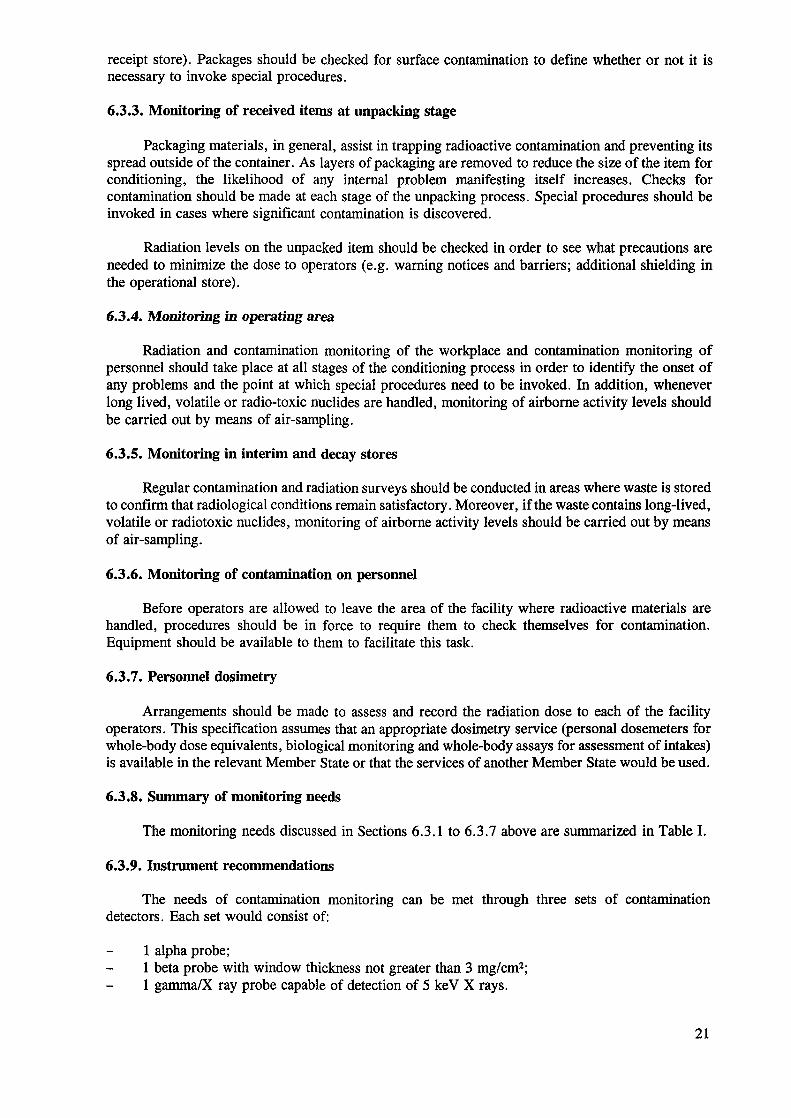
6.3.8. Summary of monitoring needs
The monitoring needs discussed in Sections 6.3.1 to 6.3.7 above are summarized in Table I.
6.3.9. Instrument recommendations
The needs of contamination monitoring can be met through three sets of contaminationdetectors. Each set would consist of:
1 alpha probe;1 beta probe with window thickness not greater than 3 mg/cm2;1 gamma/X ray probe capable of detection of 5 keV X rays.
21
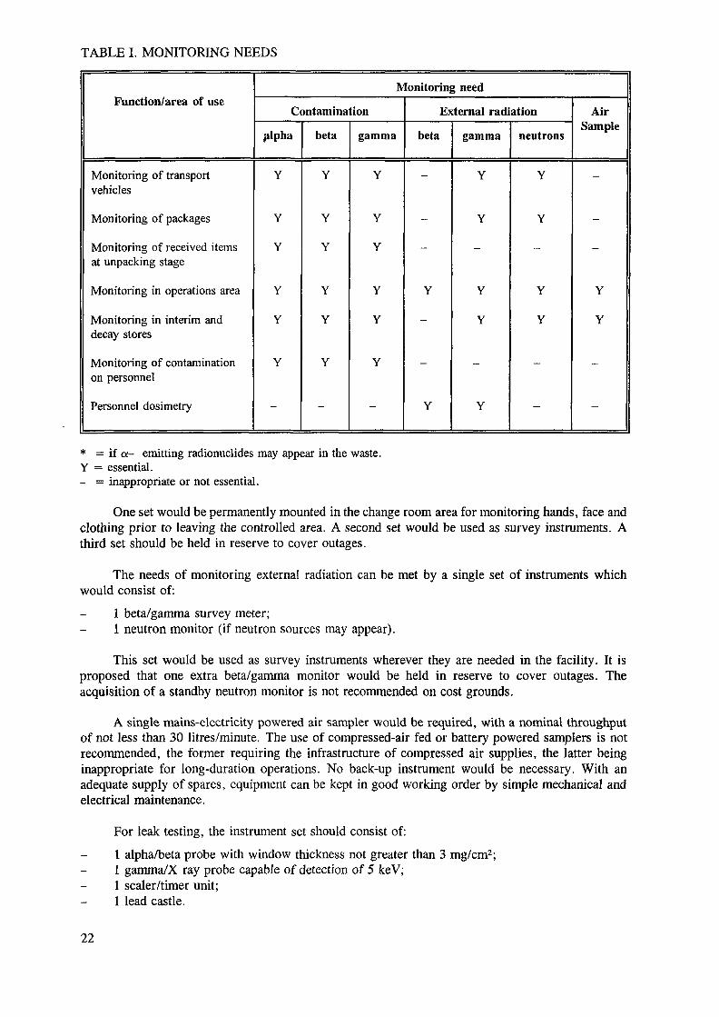
TABLE I. MONITORING NEEDS
Function/area of use
Monitoring of transportvehicles
Monitoring of packages
Monitoring of received itemsat unpacking stage
Monitoring in operations area
Monitoring in interim anddecay stores
Monitoring of contaminationon personnel
Personnel dosimetry
Monitoring need
Contamination
.alpha
Y
Y
Y
Y
Y
Y
-
bêta
Y
Y
Y
Y
Y
Y
-
gamma
Y
Y
Y
Y
Y
Y
-
External radiation
bêta
-
-
-
Y
-
-
Y
gamma
Y
Y
-
Y
Y
-
Y
neutrons
Y
Y
-
Y
Y
-
-
AirSample
-
-
-
Y
Y
-
-
* = if a- emitting radionuclides may appear in the waste.Y = essential.- = inappropriate or not essential.
One set would be permanently mounted in the change room area for monitoring hands, face andclothing prior to leaving the controlled area. A second set would be used as survey instruments. Athird set should be held in reserve to cover outages.
The needs of monitoring external radiation can be met by a single set of instruments whichwould consist of:
1 beta/gamma survey meter;1 neutron monitor (if neutron sources may appear).
This set would be used as survey instruments wherever they are needed in the facility. It isproposed that one extra beta/gamma monitor would be held in reserve to cover outages. Theacquisition of a standby neutron monitor is not recommended on cost grounds.
A single mains-electricity powered air sampler would be required, with a nominal throughputof not less than 30 litres/minute. The use of compressed-air fed or battery powered samplers is notrecommended, the former requiring the infrastructure of compressed air supplies, the latter beinginappropriate for long-duration operations. No back-up instrument would be necessary. With anadequate supply of spares, equipment can be kept in good working order by simple mechanical andelectrical maintenance.
For leak testing, the instrument set should consist of:1 alpha/beta probe with window thickness not greater than 3 mg/cm2;1 gamma/X ray probe capable of detection of 5 keV;1 sealer/timer unit;1 lead castle.
22
This equipment would be situated permanently in the Health Physics Room and used for thequantification of activity on smear tests, estimation of radon leakage from 226Ra sources/packages andthe measurement of air-sampler filter papers. The lead castle could either be purchased or madelocally; its essence is that it minimizes background radiation levels and ensures that samples andstandards are always presented to the detector in identical geometry. Other, ancillary equipmentrequired includes check sources for radiation and contamination instruments.
6.3.10. Calibration and check source recommendations
For the contamination detectors, as a minimum, a set of check sources will consist of one alphasource, one beta source and one X ray source with activities equivalent to the acceptable workinglimit which is in force in the relevant Member State. It would also consist of a further alpha source,beta source and X ray source with activities which represent one half to three quarters' full-scale-deflection on the contamination probes selected. The sources would have to be of a type recommendedfor use with contamination probes. The following recommendations are made:
for alpha: 241Am (also duplicates for X ray counting);for beta: 36C1 (for an additional source use 14C as a low energy beta source);for X ray and gamma: I29I.
The total minimum requirement is three sources each at two activity levels.
The check sources for external radiation monitors would comprise one 137Cs gamma source ofactivity around 40 MBq plus one 241 Am/Be neutron source of activity around 4000 MBq. The 137Cssource would be used to check the beta/gamma radiation monitor and the 241 Am/Be source forchecking the neutron monitor. One activity of each source would suffice because the response of theinstrument can be varied by using the inverse square law.
A secure store for the instruments and check sources would be required. Radiation andcontamination detectors do not function properly if damp. If the climatic conditions prevailing in theMember State were such that relative humidity values routinely exceed 60%, a "dry cabinet" wouldhave to be provided in which all instruments could be kept when not in use. A dry cabinet could bemade locally from a sealed cupboard with a gasketed door. A quantity of desiccant, e.g. silica gel,is used to maintain dry conditions.
6.4. DRUM HANDLING AND LIFTING
Equipment for handling and lifting drums would be required in a number of situationsincluding:
moving empty drums;moving completed drums in the operation area;moving completed drums in the receipt/dispatch area;transferring drums to the interim store;stacking drums in the interim store.
6.4.1. Moving empty drums
Empty drums can easily be man-handled, so no lifting equipment is considered necessary.
6.4.2. Moving completed drums in operation area
Completed drums could typically weigh up to 500 kg. In the operating area, the drums wouldneed to be lifted vertically to allow access to their underside for smear testing to check forcontamination. A simple, manually operated fork lift fitted with a drum grab attachment would benecessary for this. The lifting mechanism could be mechanically, or hydraulically actuated, either by
23
hand or by a battery powered motor. The hydraulically operated type is recommended because of lowcomplexity and cost.
6.4.3. Moving completed drums in receipt/dispatch area
Within the receipt/dispatch area, the main drum handling operation would be to collect the drumat the doorway into the monitoring room and to move the drum to a convenient temporary storagelocation awaiting dispatch to the interim store. A second manually operated fork lift fitted with a drumgrab attached would be used, the same type as that used in the operating area.
6.4.4. Transferring drums to interim store
It is assumed that the interim store would be located adjacent to or on the same site as the SSSFacility main building, with a reasonably smooth and level surface between the two. A hand-pulledtrolley, with a 500 kg capacity would be adequate for the transfer operation, requiring one or twooperators depending on the ground conditions. A manually operated fork lift with drum grabattachment would be required in the store to off-load the drum from the trolley.
6.4.5. Stacking drums in interim store
Two methods of stacking are anticipated: vertical or horizontal.
Vertical stacking, to a height of two drums would require the use of a manual fork lift with adrum grab attachment, the same type as required in the operating area and in the receipt/dispatcharea. This would be the same unit as used for off-loading the drum from the transfer trolley.
Horizontal stacking would first require a method of safely rotating the drum to the horizontalposition in a controlled manner. Manual equipment is available for this, but rarely for loads exceeding350 kg. Further, they generally rely on engaging into the chimb at the top of the drum. This chimbmay not be present or may be weakened on the drums which are to be stacked horizontally becausethe top has been cut off.
Once horizontal, a manual fork lift fitted with a tubular fork attachment would be required tolift the drum and stack it on to other drums. This would be the same type of unit as used for off-loading the drum from the transfer trolley.
6.4.6. Alternative handling equipment
As an alternative to the equipment proposed in sections 6.4.3 to 6.4.5 above, an electric forklift could be used for:
drum handling in the receipt/dispatch area;drum transfer to the interim store;drum stacking in the store.
An electric fork lift would certainly require less manual effort, and would be most appropriateif a large number of drums were to be handled in a short space of time. However, it is expected thatin most SSS Facilities, the rate of completed drums arising will be small (typically 100 drums in 10years), and therefore, a dedicated electric fork lift for the facility would be unnecessary. If an electricfork lift were obtained, then a battery charger would also be required.
6.4.7. Additional lifting equipment
In addition to the items noted above, other lifting equipment that may be required includes:
24
a jib attachment for the fork lift to allow the lifting of packages from transport vehicles, fortransfer around the facility, and for removing shielding pots from transport containers;lifting straps, shackles, chains and eye-bolts.
6.5. CEMENTED PACKAGE PREPARATION
In addition to a range of consumables, the main areas in which equipment is required forcemented package preparation are:
cement mixing;package weighing;package handling;source handling.
Cement mixing can either be performed manually, or with a mechanical mixer. Manual mixingwould require the simplest equipment: a shovel, a board to mix on (to protect the floor) and a bucketor hose to supply water.
If a number of packages are to be prepared, a mechanical mixer would save a great deal ofmanual effort. Mixers powered either by electric or by small combustion engines should be availablein the majority of developing Member States. The choice between electric or engine powered woulddepend on availability of fuel, cost, and which type is actually available within the particular MemberState.
Although not essential, it would be useful to record the weight of individual packages. Anaccuracy of ± 10 kg in 350-450 kg would be adequate. The type of scales with a large dial face asused in factories and warehouses, with a capacity of 500-1000 kg would be adequate.
Another optional item is equipment for testing samples of the cement mortar. Although notnecessary, it would be useful to check the compressive strength of the cement mortar being producedfrom indigenous raw materials. A simple, manually operated hydraulic 1000 kN compression frameand moulds for forming cubic blocks would be required. It could be possible to borrow thisequipment or to have the tests carried out by the local civil engineering industry.6.6. TOOLS
A good, general purpose tool-kit would be essential for the dismantling, reassembling andmaintenance of transport containers, for assembly and sealing of the over-capsules for leaking sources,and for general maintenance purposes.
6.7. CONSUMABLES
A wide range of consumables would be used in the facility. They are discussed below underthe following headings:
cemented package preparation;health physics operations;personnel clothing.
6.7.1. Cemented package preparation
The consumables required for the preparation of cemented packages are:
200 L drumsPreferably these should be the lidded type with a bolted or over-centre clamping ring for closure
of the lid. However, the use of standard "oil-drums" with the tops removed should be possible andis discussed below.
25
Whatever the lid type, the drums should be clean, and free of rust and damage, with anunmarked paint finish. In humid areas, corrosion of the drum in the interim store could be a realproblem over extended periods of storage. It is therefore recommended that all drums should bepainted inside and out, including the underside with any paint available which is suitable for metalsurfaces exposed to the weather.
The paint manufacturer's instructions, including preparation and priming of surfaces should befollowed.
Plastic sheet should be wrapped around the drum and taped inside the top to protect the drumfrom cement splashes.
If lidded drums could not be obtained, standard oil-drums could be used, with the end of thedrum removed. It would be better to remove the lid from inside the chimb rather than cutting fromthe side of the drum. Although slightly more difficult, this method results in a stronger drum, whichcould make drum handling simpler, particularly tipping prior to stacking. Equipment is available forremoving the top of the drum by this preferred method. Any sharp edges remaining from the cuttingoperation should be smoothed.
The dimensions of drums can vary widely depending on the use for which they were originallymanufactured. It is preferable, though not essential, that the drums used should all be of similardimensions to enable even and safe stacking, when the drums are eventually placed in the interimstore.
Cement
Ordinary portland cement is often available in 50 kg bags. The types and grades available willvary according to the Member State. The civil construction industry within the relevant Member Stateshould be able to advise facility operators on the supply of cement and on the types available.
Sand
Loose sand would probably be delivered by truck or skip. Again, the civil construction industrywithin the Member State should be able to advise the facility operators on the supply of sand and thetypes available.
Plastic sheet
Rolls of PVC (polyvinyl chloride) or polyethylene sheet would be required to protect floors anddrums during cement preparation, and possibly wrapping of contaminated items.
Plastic sacks
Large sacks are required for the lining of drums to be used for the collection of low level solidwaste within the facility.
Reinforcement bars
The strength and security of the package are enhanced by incorporating steel reinforcement inthe cement mortar. The type arid shape of reinforcement used would be a function of the size andshape of source(s) to be encapsulated, and the availability of steel reinforcement itself. The intentionin each case would be to form a cage around the bottom, sides and top of the source.
26
6.7.2. Health physics operations
A wide range of consumable items is required for Health Physics' operations, both for routinework and for recovery work following a contamination incident. These include:
batteries for health physics instruments;
It is recommended that rechargeable batteries are not used.
screens for alpha probes;
desiccant for use in the "dry cabinet";
hot plate or oven for drying out the desiccant;
glass fibre and charcoal papers for use in air samplers and for taking "standard" smears forquantitative assessment of activity;
polyethylene discs ( < 1 mm thick) of the same diameters as the filter papers for use in testingradium sources for leakage.
Alternatively, charcoal tablets would have to be used;
cotton waste and paper tissues for taking smears from items and work areas to check forcontamination;
swab squeegees;
These could be easily made using a wide spring clip attached to a pole. With a swab fixed inthe clip, large-area smear testing of surfaces such as walls and floors is made easily.
plastic bags;
Small bags for air-sampler papers and for contamination swabs and larger bags fordecontamination waste.
plastic sheeting (e.g. polyethylene or poly vinyl chloride) for covering areas to protect fromcontamination;
protective clothing;
Including coveralls, overshoes, head covers, plastic oversuits, industrial rubber gloves,disposable rubber or plastic gloves, respirators and their filter canisters, and possibly acompressed-air fed air-hood.
swabbing and decontamination fluids;
Including industrial alcohol and alkaline detergent based decontaminating agents.
filter packs for the ventilation system of the fume cupboard.
With the exception of compressed-air fed air-hoods and filter packs for the ventilation systemof the fume cupboard, all the items mentioned above should be easily obtainable within the MemberState. Air-hoods and filter packs may need to be imported.
27
6.7.3. Personnel clothing
It is assumed that a laundry for contaminated clothing will not be available in the developingMember State. This assumption, together with the expected low frequency of use of the SSS Facilitymeans that disposable clothing is most appropriate for operating personnel. This will include:
coveralls;overshoes;gloves.
Additional safety wear is also recommended:
steel toe-capped shoes or boots to protect the toes when heavy loads are being lifted;safety glasses or goggles to be used when cement powder is being handled and mixed to preventsplashes into the eyes;simple dust masks also to be used when cement powder is being handled to prevent theinhalation of cement dust.
7. MANAGEMENT AND STAFFING
The precise definition of the management structure of any particular SSS Facility will bedictated by local circumstances, but some general principles apply and these should be addressedwhenever a management structure is being set up. These principles are listed below and followingthem is an example of the structure involving the key personnel in a SSS Facility.
It must be noted that a small SSS Facility might not provide full time employment to allpersons. Accordingly, it might be appropriate to combine work at the SSS Facility with other suitabletasks. The posts discussed below therefore do not necessarily correspond to those of full timeemployees.
7.1. GENERAL PRINCIPLES
One person should be appointed as the head of the facility in whom is vested completeresponsibility and accountability for the operation and safety of that facility.
Sufficient numbers of staff should be appointed to cover the range of tasks identified, e.g.general management, safety (including regulatory compliance), quality, operations andadministration.
In a small SSS Facility it will probably be prudent and effective to combine tasks within a smallgroup of job holders.
It is essential to ensure that the tasks of safety and quality are independent of operationalresponsibilities and that the person(s) appointed to manage the former tasks have a directreporting line to the head of the facility.
Persons appointed to key tasks should be suitably qualified and experienced. If eitherqualifications or experience were lacking, any deficiencies would need to be put right prior totaking up the employment.
The management structure needs to be in place even when the SSS Facility is not operational.This is likely to be part of regulatory requirements in any case but, in their absence, continuityof management structure with clearly defined accountability and responsibility woulddemonstrate a sound approach to the management of radioactive materials.
28
7.2. KEY POSTS
7.2.1. Head of SSS Facility
The head of the SSS Facility is the person responsible and accountable for the operation andsafety of the facility and for quality policy concerning the facility, its processes and its systems ofmanagement.
The head should establish an operating management structure with commitment to quality policywith defined appropriate responsibilities, accountabilities and reporting levels to assist him and shouldappoint suitably qualified and experienced persons to key posts. (This is a key element of a qualityassurance system).
7.2.2. Health physicistThe duties and responsibilities of the health physicist will include:
instigation of the necessary monitoring regime;receiving and assessing the results obtained by the dosimetry service;maintenance of the dosimetry records for the appropriate period of time;taking necessary action on the basis of the radiation records and dosimetry.
7.2.3. Quality manager
The duties and responsibilities of the quality manager will include:
implementation, management and maintenance of the defined quality system;audit, internal and external, of the workings of the quality system;ensuring that cases of non-compliance and the necessary corrective actions are followed-uppromptly and to their proper and logical conclusion.
7.2.4. Operations manager
The duties and responsibilities of the operations manager will include:
receiving, storing and conditioning all spent sealed sources in accordance with Qualityarrangements;recording spent sealed sources;maintenance of records of receipt, storage and conditioning of sources for the appropriateperiod of time;managing the operational staff.
8. QUALITY ASSURANCE
The substance of this document is based on the assumption that the management of the SSSFacility will commit itself to a quality policy and will define, implement and maintain a system forassuring the quality of its products or services. Such a quality assurance system encompasses all thoseactions necessary to generate adequate confidence that the product/service will satisfy pre-determinedrequirements for quality.
In the case of the SSS Facility, the likely requirements for quality which will need to besatisfied include:
meeting radiological safety standards applicable in the Member State for protection of theoperators of the Facility and the general public;
29
ensuring that the construction of any package/drum of waste conforms to the standards laiddown by the repository accepting the waste;
demonstrating to the operator of the repository accepting the waste, adequate information aboutthe physical, chemical and radiological nature of the sources contained within the wastepackages/drums.
It is likely that the eventual disposal of prepared packages/drums of waste would take placemany years after their preparation and it will therefore be essential to protect the records generatedby the quality assurance system to ensure that they are available at the time of disposal.
The presence of an identified, auditable system for assuring the quality of the products andservices of the facility is essential for ensuring that a repository will accept the waste for disposal asthe management of the repository will invariably have to demonstrate safe disposal of the radioactivewaste to the satisfaction of the regulatory authorities in the particular Member State.
9. SAFETY CONSIDERATIONS
A safety assessment methodology would have to be adopted in building the safety case for theSSS Facility, which would demonstrate compliance with the regulatory requirements of the individualMember State. The key steps in this methodology are:
the identification of exposure to both operators and the public arising from normal operations;the identification of potential hazards arising from accident considerations;an assessment of the frequency of the accident taking place;a calculation of the consequences should the accident occur;a combination of the assessed frequency and consequences of the accident to produce a risk;a summation of the risk from all accident scenarios;a comparison of this total risk with regulatory or other criteria;a reassessment of the design of the plant if the calculated total risk exceeds the regulatorycriteria.
The safety assessment should consider the first stages of this methodology by identifying thepotential hazards arising from accidents. These are summarized below.
Internal events
transport accidents;dropped packages;packages outside specification (radiation/contamination);deterioration of packaging;inadequate shielding;adverse reaction with cement;dispatch of externally contaminated drum;failure of containment during storage.
External eventsaircraft;transport;dropped load;missile;external fires.
30
Natural eventsseismic;flood/extreme weather;impact from meteorites.
Generally, it is concluded that the volumes of material handled in the SSS Facility, and theradioactivity in the sources is relatively small compared to a similar facility in a developed country.In addition, the processes involved in the facility are simple and do not involve extreme conditionssuch as high temperatures and pressures. As a result, the hazards arising in the facility are unlikelyto result in major disruptive events anywhere in the process. Even in extreme events, such as theexternal events mentioned above, releases beyond the site boundary are unlikely.
An estimate of the risk to the operators and to the public from the operation of the SSS Facilityhas been made using several simplifying assumptions. This has shown an overall risk of prematuredeath to the operators of less than 10'6 per year and to members of the public of 10'12 per year. Theseresults are significantly less than limits set by nuclear facilities in developed countries, typically, 10"5
per year for operators, and 10"6 per year for individual public risk.
It is therefore considered that a robust safety case for the facility could be made which woulddemonstrate the compliance of the facility with the regulatory requirements of an individual MemberState.
10. COST ESTIMATE
An order of cost estimate has been prepared based on the facility construction drawings for thewarm, arid climate design and the equipment list. The estimate is summarized below in US dollars.
US $1000CAPITALFacility construction 175Store construction 60Health physics equipment 25Other equipment/furniture 40Contingency (10% for construction and 30% for equipment) 45
Total capital 345
DESIGNProfessional fees and project management 45Contingency (20%) 10
Total design 55
TOTAL PROJECT ESTIMATE 4ÖÖ
The costs are based on UK material and labour rates in 1993 and a $/£ exchange rate of£ 1 = $ 1.5. The cost of construction will vary for different geographical locations worldwide,primarily because of prevailing local labour costs. The availability and costs of materials, choice ofconstruction technique and tailoring of the design will also affect price to a varying extent. Forexample, modification of the facility and store design to suit a warm, humid climate by incorporatinga pitched roof would increase the facility cost by an estimated US $22 500.
31
REFERENCES
[1] AEA TECHNOLOGY, IAEA Spent Sealed Sources Facility, Volumes I and II, AEATechnology, Harwell (1993).
[2] INTERNATIONAL ATOMIC ENERGY AGENCY, Reference Design for A Centralized WasteProcessing and Storage Facility, IAEA-TECDOC-776, Vienna (1994).
32
QUESTIONNAIRE ON IAEA-TECDOCs
It would greatly assist the International Atomic Energy Agency in its analysis of the effective-ness of its Technical Document programme if you could kindly answer the following questionsand return the form to the address shown below. Your co-operation is greatly appreciated.
Title: Reference design for a centralized spent sealed sources facilityNumber: IAEA-TECDOC-806
1. How did you obtain this TECDOC?
[ ] From the IAEA:[ ] At own request[ ] Without request[ ] As participant at an IAEA meeting
[ ] From a professional colleague[ ] From library
2. How do you rate the content of the TECDOC?
[ ] Useful, includes information not found elsewhere[ ] Useful as a survey of the subject area[ ] Useful for reference[ ] Useful because of its international character[ ] Useful for training or study purposes[ ] Not very useful. If not, why not?
3. How do you become aware of the TECDOCs available from the IAEA?
[ ] From references in:[ ] IAEA publications[ ] Other publications
[ ] From IAEA meetings[ ] From IAEA newsletters[ ] By other means (please specify)[ ] If you find it difficult to obtain information on TECDOCs please tick this box
4. Do you make use of IAEA-TECDOCs?
[ ] Frequently[ ] Occasionally[ ] Rarely
5. Please state the institute (or country) in which you are working:
Please return to: R.F. KelleherHead, Publishing SectionInternational Atomic Energy AgencyP.O. Box 100Wagramerstrasse 5A-1400 Vienna, Austria