Embed Size (px)
Citation preview

This publication is available free of charge from https://doi.org/10.6028/NIST.NSRDS.73
NIST NSRDS 73
REFLEAK: NIST Leak/Recharge Simulation Model
for Refrigerant Blends Version 5.0
User’s Guide
J. Steven BrownPiotr A. Domanski
This publication is available free of charge from: https://doi.org/10.6028/NIST.NSRDS.73
This publication is available free of charge from https://doi.org/10.6028/NIST.NSRDS.73
NIST NSRDS 73
REFLEAK: NIST Leak/Recharge Simulation Model
for Refrigerant Blends
Version 5.0 User’s Guide
J. Steven BrownThe Catholic University of America
Piotr A. Domanski Engineering Laboratory
This publication is available free of charge from: https://doi.org/10.6028/NIST.NSRDS.73
December 2016
U.S. Department of Commerce Penny Pritzker, Secretary
National Institute of Standards and Technology Willie May, Under Secretary of Commerce for Standards and Technology and Director
This publication is available free of charge from https://doi.org/10.6028/NIST.NSRDS.73
The National Institute of Standards and Technology (NIST), uses its best efforts to deliver a high quality copy of the Database and to verify that the data contained therein have been selected on the basis of sound scientific judgment. However, NIST makes no warranties to that effect, and NIST shall not be liable for any damage that may result from errors or omissions in the Database.
(c) 1998, 1999, 2002, 2007, 2009, 2011, 2016 copyright by the U.S. Secretary of Commerce on behalf ofthe United States of America. All rights reserved. No part of this database may be reproduced, stored in aretrieval system, or transmitted, in any form or by any means, electronic, mechanical, photocopying,recording, or otherwise, without the prior written permission of the distributor.
Certain trade names and company products are mentioned in the text to specify adequately the computer products and equipment needed to use this software. In no case does such identification imply endorsement by the National Institute of Standards and Technology of these computer products and equipment, nor does it imply that the products are necessarily the best available for the purpose.
Microsoft is a registered trademark, and Windows is a trademark of Microsoft® Corporation. All other brand and product names are trademarks or registered trademarks of their respective companies.

This publication is available free of charge from https://doi.org/10.6028/NIST.NSRDS.73
ACKNOWLEDGMENTS
We acknowledge Dr. David Didion and Dr. Min Soo Kim for developing earlier versions of this simulation model; Dr. Riccardo Brignoli for his help in developing the visual interface; and Dr. Eric Lemmon, Dr. Mark O. McLinden and Dr. Marcia Huber for their work with REFPROP upon which this simulation model isbased.

This publication is available free of charge from https://doi.org/10.6028/NIST.NSRDS.73
CONTENTS
1. INTRODUCTION ...................................................................................................................................... 1
2. INSTALLATION ........................................................................................................................................ 2
3. MODELING OF LEAK AND RECHARGE PROCESS ............................................................................. 2
4. DESCRIPTION OF THE SIMULATION MODEL...................................................................................... 3
REFERENCES ............................................................................................................................................. 4
Appendix A. SAMPLE RUN FOR LEAK PROCESS ................................................................................... 5
Appendix B. SAMPLE RUN FOR LEAK AND RECHARGE PROCESS ................................................... 13
Appendix C. ICONS ................................................................................................................................... 15
Appendix D. SINGLE-COMPOUND REFRIGERANTS AVAILABLE IN REFLEAK .................................. 16
Appendix E. PREDEFINED REFRIGERANT BLENDS AVAILABLE IN REFLEAK ................................. 18
Appendix F. CALCULATION OF INITIAL VOLUMETRIC QUALITY BASED ON FRACTION
OF MAXIMUM LIQUID FILL ................................................................................................. 20
Appendix G. CONTACTS ......................................................................................................................... 21
This publication is available free of charge from https://doi.org/10.6028/NIST.NSRDS.73
REFLEAK 1
1. INTRODUCTION
As alternatives to refrigerants with a high global warming potential, blends of two or more refrigerants are being utilized as working fluids in heat-pump, air-conditioning, and refrigeration systems, and in organic Rankine cycles. Generally, these blends form zeotropes, which show temperature and composition changes during evaporation, condensation, or flashing process whether it be intended (i.e., through an expansion device) or unintended (e.g., a leak from a container or system). For zeotropic blends, it may be important and necessary to predict the composition change for any of these leak conditions.
REFLEAK simulates leak and recharge processes for refrigerant zeotropic blends. This Windows-based simulation model provides an easy-to-use package that allows estimation of composition changes of zeotropic blends in leak and recharge processes for either vapor or liquid leaks under isothermal or adiabatic conditions. The generic model of these processes used in REFLEAK and example simulation studies are presented in [1, 2]. Other computer simulations and laboratory leak measurements of specific blends are reported in [3, 4].
Thermodynamic properties of the refrigerant blends are calculated using the NIST Reference Fluid Thermodynamic and Transport Properties Database (REFPROP): Version 9.1 [5].
Uncertainties in Calculated Properties
The objective in selecting fluid property models for use in REFPROP was to implement the most accurate models currently available. The user should be aware that the uncertainties in these models vary considerably depending on the fluid, property, and thermodynamic state. It is thus impossible to give a simple, global statement of uncertainties. Even for the most-studied fluids with equations of state based on accurate, wide-ranging data, uncertainties are complicated functions of temperature and pressure. The interested user is referred to REFPROP’s original literature sources for details.
The user is further cautioned that, by the very nature of using computational results, property data are often displayed with more digits than can be justified based on the accuracy of the property models or the uncertainties in the experimental data to which the models were fitted.
Remarks
Occasionally a convergence problem may occur in calculating thermodynamic properties of some azeotropic or near-azeotropic blends, which will result in an error message. Since this will typically occur only for a narrow band of input conditions, the user may want to change the initial input conditions and try the analysis again, or perhaps the property values obtained on either side of the error zone can be interpolated to the user’s satisfaction.
The simulation model provides 'Help' sections with several keywords to assist the user.
NIST regularly updates the REFPROP database [5]. When this occurs, this simulation model will be revised to reflect the new property routines.
Compared to Version 4.0, this version of REFLEAK includes a Graphical User Interface (GUI) built on the .NET platform of Microsoft® and extends to 10 the number of refrigerants allowed in a blend. As already implemented in Version 4.0, this version also includes an input option for the initial volumetric quality based on the maximum liquid fill at a different fill temperature. This option is consistent with the specification of the initial volumetric quality used in ANSI/ASHRAE Standard 34 [6].
This publication is available free of charge from https://doi.org/10.6028/NIST.NSRDS.73
REFLEAK 2
2. INSTALLATION
System Requirements
Free space for complete installation: 10.0 MB PC with Microsoft® Windows® 7, 8 or 10 operating systems.
Installation Procedure
Execute the REFLEAK installation file setup.exe with Refleak Installer.msi residing in the same directory. Follow the on-screen instructions.
To run the program, click on the Refleak icon on the Start Menu.
3. MODELING OF LEAK AND RECHARGE PROCESS
During a leak process of a refrigerant zeotropic blend, fluid in a vapor or liquid phase escapes from the system, where preferential evaporation of one or more components makes the composition in the vapor phase different from that in the liquid phase.
Inherently, the temperature of the fluid in the system decreases since the energy required for vaporization is taken from the refrigerant remaining in the system and from the system material.
Two idealized cases are considered in the simulation model: (1) isothermal leaks and (2) adiabatic leaks. An isothermal leak process represents a very slow leak situation, in which the temperature of the system remains constant because of the heat transfer through the walls from the environment. In an adiabatic leak process, it is assumed that the refrigerant leaks so quickly that no heat is transferred through the walls, and thus the temperature in the system decreases as the leak progresses. A comparison of experimental data with REFLEAK simulations has shown that slow leaks are well predicted by the isothermal assumption. However, all real systems have non-negligible heat capacity, which will release some thermal energy during the expanding vaporization process as the liquid temperature drops. Thus, an actual fast leak process probably falls somewhere between the adiabatic and isothermal assumptions.
In order to model these leak situations, the following assumptions are made:
(1) During the leak, only one phase (vapor or liquid) is escaping from the system.(2) The refrigerant blend inside the system is at a vapor-liquid equilibrium state.(3) The leak process is either isothermal or adiabatic.(4) The escaping refrigerant has the same composition as the vapor inside the system during a vapor
leak, and the same composition as the liquid during a liquid leak.
In the recharging process, a leak of a portion of the system charge is simulated, and then the system is recharged with a refrigerant of the original composition. The recharged mass is equal to that which has leaked from the system. After recharging during an adiabatic leak process, the temperature in the system is "reset" to the initial temperature.
The leak process is simulated in a quasi-steady manner by alternate steps of refrigerant escaping and adjustment of the remaining refrigerant to thermodynamic equilibrium. The thermodynamic properties are calculated using the property routines included in the NIST Reference Fluid Thermodynamic and Transport Properties Database (REFPROP): Version 9.1 [5]. Therefore, all limitations applicable to REFPROP (e.g., avoiding the region near the critical point) are applicable to REFLEAK.
This publication is available free of charge from https://doi.org/10.6028/NIST.NSRDS.73
REFLEAK 3
4. DESCRIPTION OF THE SIMULATION MODELThe leak/recharge simulation model consists of three parts: (1) a pre-processing section to input required data, (2) a main section to simulate the leak/recharge process, and (3) a post-processing section to display calculated results, and save and/or print graphs.
After initiating the simulation model, a user can take the following actions:
(1) Select the refrigerant blend for the leak/recharge simulation. Note: the refrigerant blend must bechosen before any other data can be input or action taken, except that of changing units.a. For a predefined blend, press the appropriately labeled command button.b. For a user-defined blend press the appropriately labeled command button.
i. Select up to ten components from the list box.ii. Specify the mass (or mole) fractions for each component; in either case, they must sum to
one.iii. If desired, the user-defined blend can be stored for later retrieval as a predefined blend.
(2) Choose the simulation mode: leak only or leak/recharge.(3) Choose the type of leak: isothermal or adiabatic.(4) Choose the leaking phase: vapor or liquid.(5) Choose IP (Inch-Pound) or SI units.(6) Input the initial leak condition by specifying:
a. Initial refrigerant temperature.b. Initial vapor volumetric quality.
Optionally, the initial vapor volumetric quality at the leak initial temperature can be calculatedfrom a fraction of the maximum liquid fill at a given fill temperature. This option follows thespecification of the initial volumetric quality used in ANSI/ASHRAE Standard 34 [6]. AppendixF of this report outlines the calculation procedure used by REFLEAK. Note: if this option ischosen, the user must press the ‘Calculate’ command button before the ‘Analyze’ commandbutton will be highlighted and a simulation can proceed.
(7) Input the number of recharge cycles when simulating the leak/recharge process.(8) Input the mass percentage loss for recharging the system when simulating the leak/recharge
process.
After the input data have been specified, click the 'Analyze' command button. After the analysis has been completed, a plot window will appear displaying the simulation results.
In the post-processing section, the following functions are provided:
(1) Display of the calculated results in graphical format; the graph shows compositions of the liquidand vapor phases as a function of the leaked mass fraction. A vertical bar in the graph indicatesspecific values corresponding to the x-axis location (leaked mass fraction). The location of thevertical bar can be changed to a specific value of the leaked mass fraction via the slider bar locatedin the lower right corner of the screen. Data at this specific value of leaked mass fraction isdisplayed in the lower part of the graph for temperature, pressure, volumetric quality (void fraction),liquid specific volume, and vapor specific volume. In lieu of compositions of the liquid and vaporphases being plotted along the y-axis, temperature or pressure can be plotted instead using the‘Option’ command button and then by using the ‘Y Data’ frame.
(2) The ‘Option’ command button can also be used to change the limits of the y-axis by using the ‘y-Axis Limits’ frame.
(3) Print the output data and/or graph.(4) Redraw the graph.(5) Close the display of data and graph.
The input data can be stored to a specific file using the ‘Save’ or ‘Save as’ command from the File menu.
After a simulation has been completed, another simulation can be executed from the main window. The subsequent simulation can be performed by inputting, if so desired, a different refrigerant blend and/or different initial conditions, both by repeating the several steps described earlier in this section. If a user
This publication is available free of charge from https://doi.org/10.6028/NIST.NSRDS.73
REFLEAK 4
selects 'New' from the 'File' menu, all the input data are set to the default values. Note: if the user modifies any of the data after a simulation has been run, the previous simulation results will be removed from memory.
REFERENCES
[1] Kim, M.S., Didion, D.A., 1995. Simulation of Isothermal and Adiabatic Leak Processes of ZeotropicRefrigerant Mixtures, Int. Journal of HVAC&R Research, ASHRAE, Atlanta, Georgia, 1(3), 3-20.
[2] Kim, M.S., Didion, D.A., 1995. Simulation of a Leak/Recharge Process of Refrigerant Mixtures, Int.Journal of HVAC&R Research, ASHRAE, Atlanta, Georgia, 1(3), 242-254.
[3] Shiflett, M.B., Yokozeki, A., Reed, P.R., 1992. Property and Performance Evaluation of 'SUVA' HPRefrigerants as R-502 Alternatives, Proc. of 1992 Int. Refrigeration Conference, Purdue Univ., WestLafayette, Indiana, 1, 15-22.
[4] Kruse, H., Rinne, F., 1992. Performance and Leakage Investigations of Refrigeration and Air-Conditioning Systems Using Refrigerant Mixtures as Working Fluids, Proc. of 1992 Int. RefrigerationConference, Purdue Univ., West Lafayette, Indiana, 2, 621-630.
[5] Lemmon, E. W., Huber, M. L., McLinden, M. O., 2013. NIST Reference Fluid Thermodynamic andTransport Properties Database (REFPROP): Version 9.1. NIST Standard Reference Database 23,National Institute of Standards and Technology, Gaithersburg, Maryland, U.S.A.
[6] American Society of Heating, Refrigerating, and Air-Conditioning Engineers, Inc., (ASHRAE), 2013.ANSI/ASHRAE Standard 34-2013, Designation and Safety Classification of Refrigerants.
[7] McLinden, M.O., 2007, Private communication.
This publication is available free of charge from https://doi.org/10.6028/NIST.NSRDS.73
REFLEAK 5
Appendix A
SAMPLE RUN FOR LEAK PROCESS
A sample execution of the leak/recharge simulation model for a leak process is briefly described below. In this example, a leak process for an R32/134a blend with a composition of 30/70 mass percentage is simulated. The leak process is assumed to be isothermal, and the leaking refrigerant is vapor. The initial temperature is 25 °C, and the initial volumetric quality, which is the ratio of the volume of vapor to the total volume, is 0.25.
To start the simulation model double click the REFLEAK icon. An introductory screen appears.
Figure A-1 Introductory screen
The main input screen is then displayed (Figure A-2). The first required action is to select the refrigerant. For this example, click the command button ‘Define New Blend’, after which Figure A-3 will appear.
Figure A-2 Main window for data entry
This publication is available free of charge from https://doi.org/10.6028/NIST.NSRDS.73
REFLEAK 6
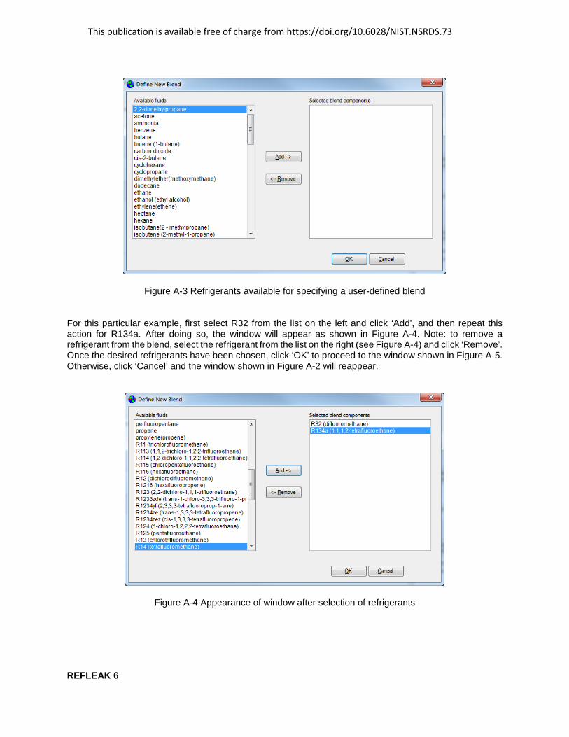
Figure A-3 Refrigerants available for specifying a user-defined blend
For this particular example, first select R32 from the list on the left and click ‘Add’, and then repeat this action for R134a. After doing so, the window will appear as shown in Figure A-4. Note: to remove a refrigerant from the blend, select the refrigerant from the list on the right (see Figure A-4) and click ‘Remove’. Once the desired refrigerants have been chosen, click ‘OK’ to proceed to the window shown in Figure A-5. Otherwise, click ‘Cancel’ and the window shown in Figure A-2 will reappear.
Figure A-4 Appearance of window after selection of refrigerants
This publication is available free of charge from https://doi.org/10.6028/NIST.NSRDS.73
REFLEAK 7
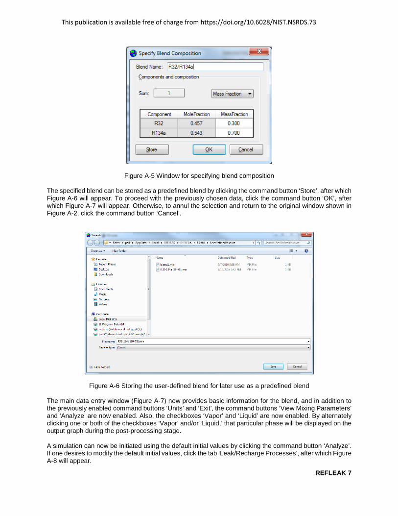
Figure A-5 Window for specifying blend composition
The specified blend can be stored as a predefined blend by clicking the command button ‘Store’, after which Figure A-6 will appear. To proceed with the previously chosen data, click the command button ‘OK’, after which Figure A-7 will appear. Otherwise, to annul the selection and return to the original window shown in Figure A-2, click the command button ‘Cancel’.
Figure A-6 Storing the user-defined blend for later use as a predefined blend
The main data entry window (Figure A-7) now provides basic information for the blend, and in addition to the previously enabled command buttons ‘Units’ and ‘Exit’, the command buttons ‘View Mixing Parameters’ and ‘Analyze’ are now enabled. Also, the checkboxes ‘Vapor’ and ‘Liquid’ are now enabled. By alternately clicking one or both of the checkboxes ‘Vapor’ and/or ‘Liquid,’ that particular phase will be displayed on the output graph during the post-processing stage.
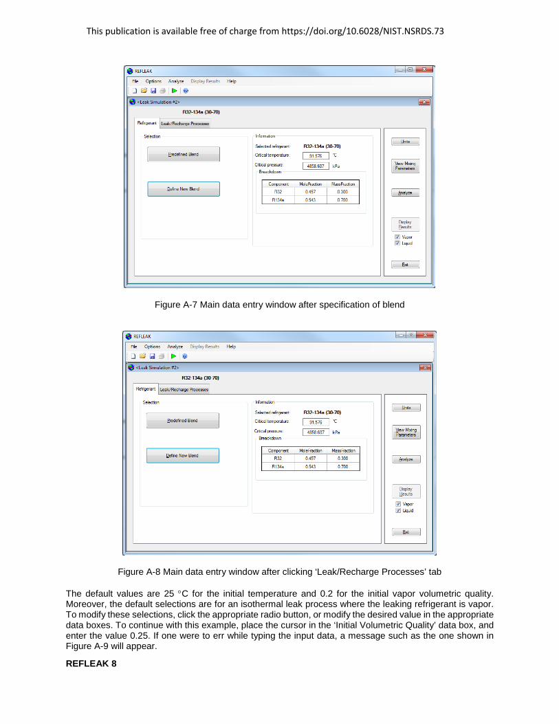
A simulation can now be initiated using the default initial values by clicking the command button ‘Analyze’. If one desires to modify the default initial values, click the tab ‘Leak/Recharge Processes’, after which Figure A-8 will appear.
This publication is available free of charge from https://doi.org/10.6028/NIST.NSRDS.73
REFLEAK 8
Figure A-7 Main data entry window after specification of blend
Figure A-8 Main data entry window after clicking ‘Leak/Recharge Processes’ tab
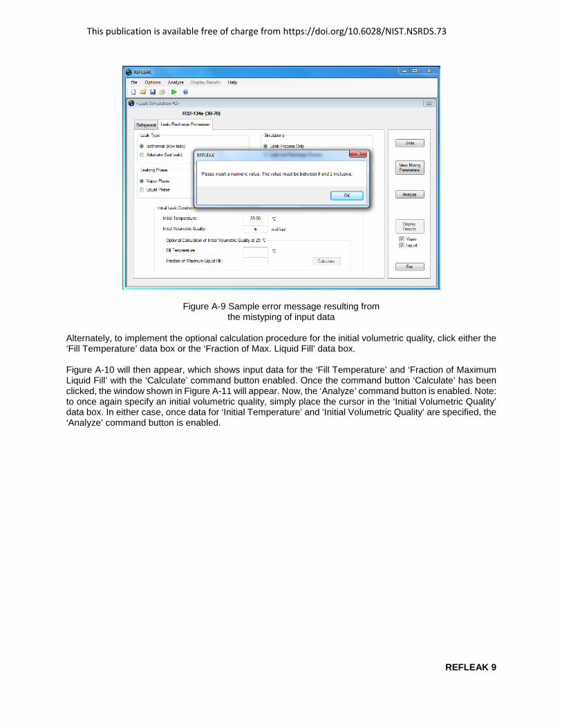
The default values are 25 °C for the initial temperature and 0.2 for the initial vapor volumetric quality. Moreover, the default selections are for an isothermal leak process where the leaking refrigerant is vapor. To modify these selections, click the appropriate radio button, or modify the desired value in the appropriate data boxes. To continue with this example, place the cursor in the ‘Initial Volumetric Quality’ data box, and enter the value 0.25. If one were to err while typing the input data, a message such as the one shown in Figure A-9 will appear.
This publication is available free of charge from https://doi.org/10.6028/NIST.NSRDS.73
REFLEAK 9
Figure A-9 Sample error message resulting from the mistyping of input data
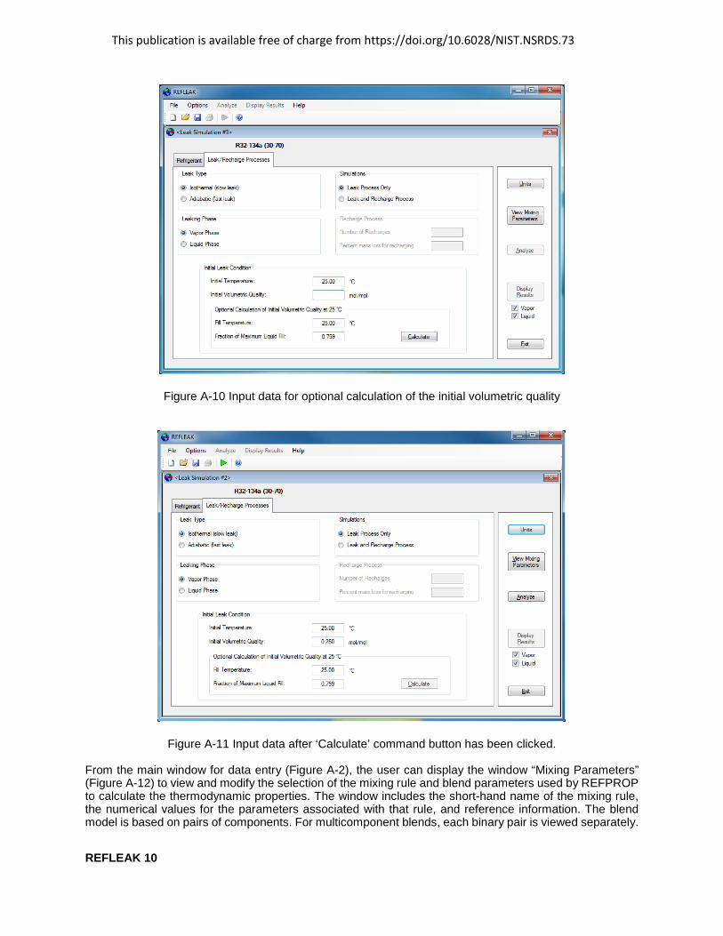
Alternately, to implement the optional calculation procedure for the initial volumetric quality, click either the ‘Fill Temperature’ data box or the ‘Fraction of Max. Liquid Fill’ data box.
Figure A-10 will then appear, which shows input data for the ‘Fill Temperature’ and ‘Fraction of Maximum Liquid Fill’ with the ‘Calculate’ command button enabled. Once the command button ‘Calculate’ has been clicked, the window shown in Figure A-11 will appear. Now, the ‘Analyze’ command button is enabled. Note: to once again specify an initial volumetric quality, simply place the cursor in the ‘Initial Volumetric Quality’ data box. In either case, once data for ‘Initial Temperature’ and ‘Initial Volumetric Quality’ are specified, the ‘Analyze’ command button is enabled.
This publication is available free of charge from https://doi.org/10.6028/NIST.NSRDS.73
REFLEAK 10
Figure A-10 Input data for optional calculation of the initial volumetric quality
Figure A-11 Input data after ‘Calculate’ command button has been clicked.
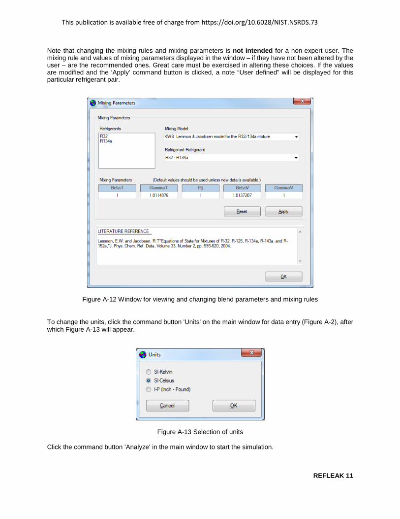
From the main window for data entry (Figure A-2), the user can display the window “Mixing Parameters” (Figure A-12) to view and modify the selection of the mixing rule and blend parameters used by REFPROP to calculate the thermodynamic properties. The window includes the short-hand name of the mixing rule, the numerical values for the parameters associated with that rule, and reference information. The blend model is based on pairs of components. For multicomponent blends, each binary pair is viewed separately.
This publication is available free of charge from https://doi.org/10.6028/NIST.NSRDS.73
REFLEAK 11
Note that changing the mixing rules and mixing parameters is not intended for a non-expert user. The mixing rule and values of mixing parameters displayed in the window – if they have not been altered by the user – are the recommended ones. Great care must be exercised in altering these choices. If the values are modified and the ‘Apply’ command button is clicked, a note “User defined” will be displayed for this particular refrigerant pair.
Figure A-12 Window for viewing and changing blend parameters and mixing rules
To change the units, click the command button 'Units' on the main window for data entry (Figure A-2), after which Figure A-13 will appear.
Figure A-13 Selection of units
Click the command button 'Analyze' in the main window to start the simulation.
This publication is available free of charge from https://doi.org/10.6028/NIST.NSRDS.73
REFLEAK 12
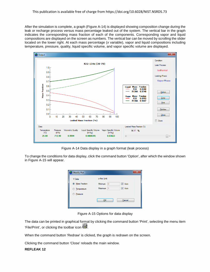
After the simulation is complete, a graph (Figure A-14) is displayed showing composition change during the leak or recharge process versus mass percentage leaked out of the system. The vertical bar in the graph indicates the corresponding mass fraction of each of the components. Corresponding vapor and liquid compositions are displayed on the screen as numbers. The vertical bar can be moved by scrolling the slider located on the lower right. At each mass percentage (x variable), vapor and liquid compositions including temperature, pressure, quality, liquid specific volume, and vapor specific volume are displayed.
Figure A-14 Data display in a graph format (leak process)
To change the conditions for data display, click the command button 'Option', after which the window shown in Figure A-15 will appear.
Figure A-15 Options for data display
The data can be printed in graphical format by clicking the command button 'Print', selecting the menu item
‘File/Print’, or clicking the toolbar icon .
When the command button 'Redraw' is clicked, the graph is redrawn on the screen.
Clicking the command button 'Close' reloads the main window.

This publication is available free of charge from https://doi.org/10.6028/NIST.NSRDS.73
REFLEAK 13
Appendix B
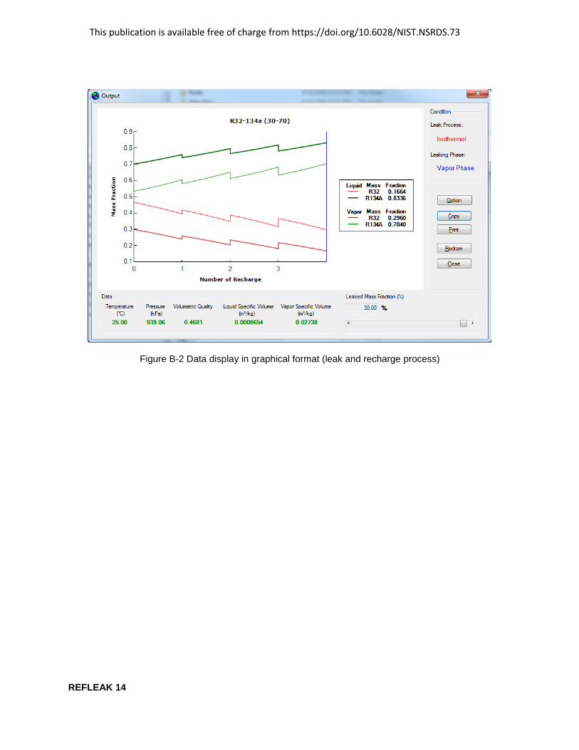
SAMPLE RUN FOR LEAK AND RECHARGE PROCESS
This section describes an example of a leak and recharge process for an R32/134a blend simulated with an initial composition of 30/70 mass percentage. The leak process is assumed to be isothermal, and the leaking refrigerant is vapor. It is also assumed that the system is recharged when 30 % of the initial mass has leaked out of the system, and that the system is recharged three times with the initial refrigerant composition. The initial temperature is 25 °C, and the initial volumetric quality, which is the ratio of the volume of vapor to the total volume, is 0.25.
Double click the REFLEAK icon.
An introductory screen appears (See Figure A-1).
Follow the steps in Appendix A to select the refrigerant. Click the tab ‘Leak/Recharge Processes’ and modify the ‘Initial Volumetric Quality’ following the steps in Appendix A.
Click the radio button ‘Leak and Recharge Process’. Input 3 into the ‘Number of recharges’ data box, and input 30 in the “% mass loss for recharging’ data box, as shown in Figure B-1.
Figure B-1 Data entry window for the leak and recharge simulation example of this Appendix
Click the command button ‘Analyze' to start the simulation. After the simulation, the output is displayed in graphical format as shown in Figure B-2.
This publication is available free of charge from https://doi.org/10.6028/NIST.NSRDS.73
REFLEAK 14
Figure B-2 Data display in graphical format (leak and recharge process)
This publication is available free of charge from https://doi.org/10.6028/NIST.NSRDS.73
REFLEAK 15
Appendix C
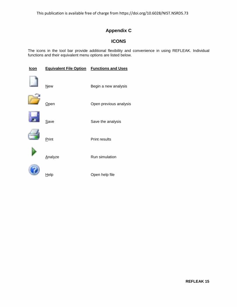
ICONS
The icons in the tool bar provide additional flexibility and convenience in using REFLEAK. Individual functions and their equivalent menu options are listed below.
Icon Equivalent File Option Functions and Uses
New Begin a new analysis
Open Open previous analysis
Save Save the analysis
Print Print results
Analyze Run simulation
Help Open help file

This publication is available free of charge from https://doi.org/10.6028/NIST.NSRDS.73
REFLEAK 16
Appendix D
SINGLE-COMPOUND REFRIGERANTS AVAILABLE IN REFLEAK
Short Name Full Chemical Name Tcrit Tcrit (°C) (°F)
R-11 trichlorofluoromethane 198.0 388.3 R-12 dichlorodifluoromethane 112.0 233.6 R-13 chlorotrifluoromethane 29.2 84.6 R-13I1 trifluoroiodomethane 123.3 253.9 R-14 tetrafluoromethane -45.6 -50.2R-21 dichlorofluoromethane 178.3 353.0R-22 chlorodifluoromethane 96.2 205.1R-23 trifluoromethane 25.9 78.7 R-32 difluoromethane 78.1 172.6 R-40 methyl chloride 143.2 289.7 R-41 fluoromethane 44.1 111.4 R-50 methane -116.7 -82.7R-113 1,1,2–trichloro–1,2,2–trifluoroethane 214.1 417.3R-114 1,2–dichloro–1,1,2,2–tetrafluoroethane 145.7 294.2R-115 chloropentafluoroethane 80.0 175.9R-116 hexafluoroethane 19.9 67.8 R-123 1,1–dichloro–2,2,2–trifluoroethane 183.7 362.6 R-124 1–chloro–1,2,2,2–tetrafluoroethane 122.3 252.1 R-125 pentafluoroethane 66.2 151.1 R-134a 1,1,1,2–tetrafluoroethane 101.1 213.9 R-141b 1,1–dichloro–1–fluoroethane 204.2 399.6 R-142b 1–chloro–1,1–difluoroethane 137.1 278.8 R-143a 1,1,1–trifluoroethane 72.9 163.2 R-152a 1,1-difluoroethane 113.3 235.9 R-161 fluoroethane 102.2 215.9 R-170 ethane 32.2 89.9 R-218 octafluoropropane 161.5 72.0 R-227ea 1,1,1,2,3,3,3–heptafluoropropane 102.8 217.0 R-236ea 1,1,1,2,3,3–hexafluoropropane 139.3 282.7 R-236fa 1,1,1,3,3,3–hexafluoropropane 124.9 256.9 R-245ca 1,1,2,2,3–pentafluoropropane 174.4 346.0 R-245fa 1,1,1,3,3–pentafluoropropane 154.1 309.3 R-365mfc 1,1,1,3,3-pentafluorobutane 186.9 368.3 R-290 propane 96.7 206.1 R-C318 octafluorocyclobutane 115.2 239.4 R-600 butane 152.0 305.6 R-600a isobutane or 2–methylpropane 134.7 274.5 R-717 ammonia 132.3 270.1 R-744 carbon dioxide 31.1 87.9 R-1150 ethylene 9.2 48.6 R-1216 hexafluoropropene 85.8 186.4 R-1233zd(E) 1-chloro-3,3,3-trifluoroprop-1-ene 166.5 330.1 R-1234yf 2,3,3,3-tetrafluoroprop-1-ene 94.7 202.5 R-1234ze(E) trans-1,3,3,3-tetrafluoropropene 109.4 228.9 R-1234ze(Z) cis-1,3,3,3-tetrafluoropropene 150.1 302.2 R-1270 propylene or propene 92.4 198.4 RE-143a methyl-trifluoromethyl-ether 104.8 220.6 RE-170 dimethylether or ethylene oxide 127.2 260.9

This publication is available free of charge from https://doi.org/10.6028/NIST.NSRDS.73
REFLEAK 17
Short Name Full Chemical Name Tcrit Tcrit (°C) (°F)
RE-245cb2 methyl-pentafluoroethyl-ether 133.7 272.6 RE-245fa2 2,2,2-trifluoroethyl-difluoromethyl-ether 171.7 341.1 CH3CH2CH=CH2 1-butene 146.1 295.1 Cyclo-C3H6 cyclopropane 125.2 257.3 C2H6O ethanol or ethyl alcohol 240.8 465.4 CH(CH3)3 isobutene or 2-methyl-1-propene 144.9 292.9 (CH3)2CH(CH2)2CH3 isohexane or 2-methylpentane 224.6 436.2 (CH3)2CHCH2CH3 isopentane or 2-methylbutane 187.2 369.0 CH3OH methanol 239.5 463.0 CH3-3(CH2)-CH3 pentane 196.6 385.8 C3H6O acetone 235.0 454.9 C4H8 cis-butene or cis-2-butene 162.6 324.7 C4H8 trans-butene or trans-2-butene 155.5 311.8 C5F12 perfluoropentane or dodecafluoropentane 147.4 297.3 C5H12 neopentane or 2,2-dimethylpropane 160.6 321.1 C6H6 benzene 288.9 552.0 C6H12 cyclohexane 280.5 536.9 C6H14 hexane 234.7 454.4 C7H16 heptane 267.0 512.6 C12H26 dodecane 385.0 724.9 SF6 sulfur hexafluoride 45.6 114.0
The user can add new fluids to REFLEAK by placing new fluid files into the “fluids” folder. The fluid file must be compatible with REFPROP [1], and its name must start with “R” or “r” (e.g., Rnew2.fld or r754.fld will be recognized by REFLEAK as fluid files).
This publication is available free of charge from https://doi.org/10.6028/NIST.NSRDS.73
REFLEAK 18
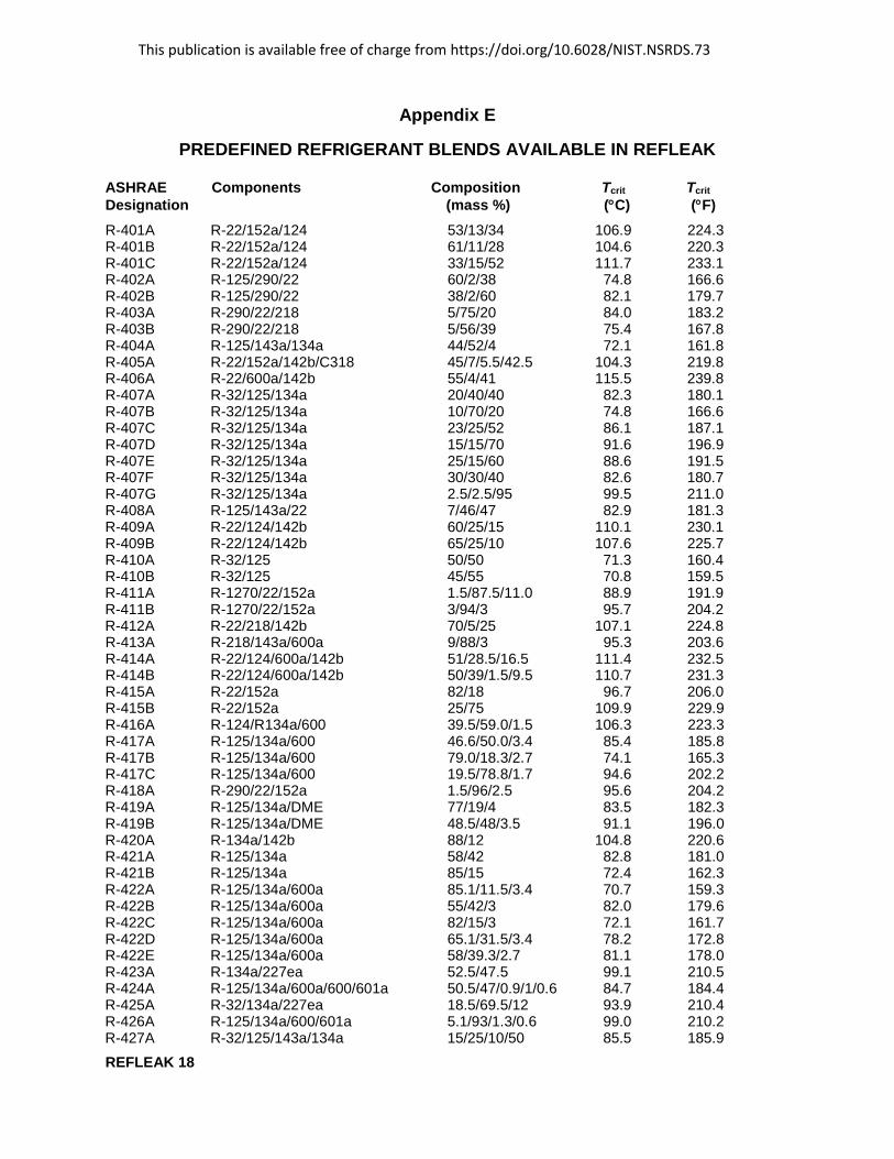
Appendix E
PREDEFINED REFRIGERANT BLENDS AVAILABLE IN REFLEAK
ASHRAE Components Composition Tcrit TcritDesignation (mass %) (°C) (°F) R-401A R-22/152a/124 53/13/34 106.9 224.3 R-401B R-22/152a/124 61/11/28 104.6 220.3 R-401C R-22/152a/124 33/15/52 111.7 233.1 R-402A R-125/290/22 60/2/38 74.8 166.6 R-402B R-125/290/22 38/2/60 82.1 179.7 R-403A R-290/22/218 5/75/20 84.0 183.2 R-403B R-290/22/218 5/56/39 75.4 167.8 R-404A R-125/143a/134a 44/52/4 72.1 161.8 R-405A R-22/152a/142b/C318 45/7/5.5/42.5 104.3 219.8 R-406A R-22/600a/142b 55/4/41 115.5 239.8 R-407A R-32/125/134a 20/40/40 82.3 180.1 R-407B R-32/125/134a 10/70/20 74.8 166.6 R-407C R-32/125/134a 23/25/52 86.1 187.1 R-407D R-32/125/134a 15/15/70 91.6 196.9 R-407E R-32/125/134a 25/15/60 88.6 191.5 R-407F R-32/125/134a 30/30/40 82.6 180.7 R-407G R-32/125/134a 2.5/2.5/95 99.5 211.0 R-408A R-125/143a/22 7/46/47 82.9 181.3 R-409A R-22/124/142b 60/25/15 110.1 230.1 R-409B R-22/124/142b 65/25/10 107.6 225.7 R-410A R-32/125 50/50 71.3 160.4 R-410B R-32/125 45/55 70.8 159.5 R-411A R-1270/22/152a 1.5/87.5/11.0 88.9 191.9 R-411B R-1270/22/152a 3/94/3 95.7 204.2 R-412A R-22/218/142b 70/5/25 107.1 224.8 R-413A R-218/143a/600a 9/88/3 95.3 203.6 R-414A R-22/124/600a/142b 51/28.5/16.5 111.4 232.5 R-414B R-22/124/600a/142b 50/39/1.5/9.5 110.7 231.3 R-415A R-22/152a 82/18 96.7 206.0 R-415B R-22/152a 25/75 109.9 229.9 R-416A R-124/R134a/600 39.5/59.0/1.5 106.3 223.3 R-417A R-125/134a/600 46.6/50.0/3.4 85.4 185.8 R-417B R-125/134a/600 79.0/18.3/2.7 74.1 165.3 R-417C R-125/134a/600 19.5/78.8/1.7 94.6 202.2 R-418A R-290/22/152a 1.5/96/2.5 95.6 204.2 R-419A R-125/134a/DME 77/19/4 83.5 182.3 R-419B R-125/134a/DME 48.5/48/3.5 91.1 196.0 R-420A R-134a/142b 88/12 104.8 220.6 R-421A R-125/134a 58/42 82.8 181.0 R-421B R-125/134a 85/15 72.4 162.3 R-422A R-125/134a/600a 85.1/11.5/3.4 70.7 159.3 R-422B R-125/134a/600a 55/42/3 82.0 179.6 R-422C R-125/134a/600a 82/15/3 72.1 161.7 R-422D R-125/134a/600a 65.1/31.5/3.4 78.2 172.8 R-422E R-125/134a/600a 58/39.3/2.7 81.1 178.0 R-423A R-134a/227ea 52.5/47.5 99.1 210.5 R-424A R-125/134a/600a/600/601a 50.5/47/0.9/1/0.6 84.7 184.4 R-425A R-32/134a/227ea 18.5/69.5/12 93.9 210.4 R-426A R-125/134a/600/601a 5.1/93/1.3/0.6 99.0 210.2 R-427A R-32/125/143a/134a 15/25/10/50 85.5 185.9
This publication is available free of charge from https://doi.org/10.6028/NIST.NSRDS.73
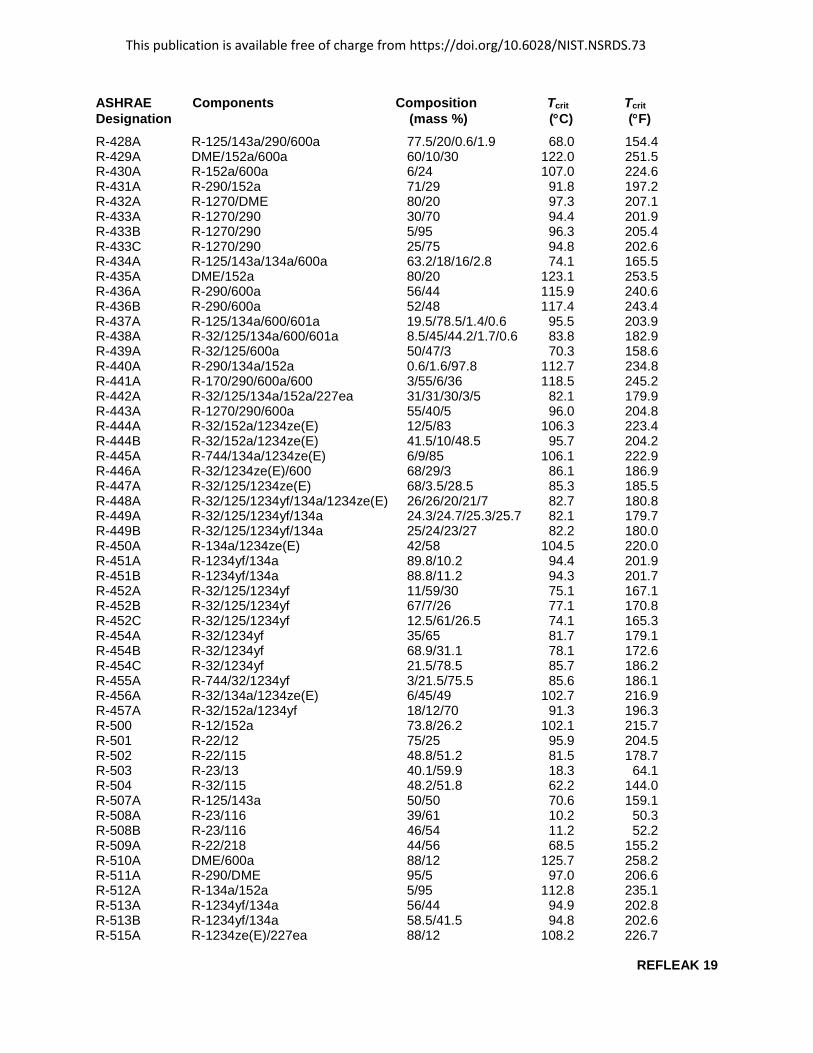
REFLEAK 19
ASHRAE Components Composition Tcrit TcritDesignation (mass %) (°C) (°F) R-428A R-125/143a/290/600a 77.5/20/0.6/1.9 68.0 154.4 R-429A DME/152a/600a 60/10/30 122.0 251.5 R-430A R-152a/600a 6/24 107.0 224.6 R-431A R-290/152a 71/29 91.8 197.2 R-432A R-1270/DME 80/20 97.3 207.1 R-433A R-1270/290 30/70 94.4 201.9 R-433B R-1270/290 5/95 96.3 205.4 R-433C R-1270/290 25/75 94.8 202.6 R-434A R-125/143a/134a/600a 63.2/18/16/2.8 74.1 165.5 R-435A DME/152a 80/20 123.1 253.5 R-436A R-290/600a 56/44 115.9 240.6 R-436B R-290/600a 52/48 117.4 243.4 R-437A R-125/134a/600/601a 19.5/78.5/1.4/0.6 95.5 203.9 R-438A R-32/125/134a/600/601a 8.5/45/44.2/1.7/0.6 83.8 182.9 R-439A R-32/125/600a 50/47/3 70.3 158.6 R-440A R-290/134a/152a 0.6/1.6/97.8 112.7 234.8 R-441A R-170/290/600a/600 3/55/6/36 118.5 245.2 R-442A R-32/125/134a/152a/227ea 31/31/30/3/5 82.1 179.9 R-443A R-1270/290/600a 55/40/5 96.0 204.8 R-444A R-32/152a/1234ze(E) 12/5/83 106.3 223.4 R-444B R-32/152a/1234ze(E) 41.5/10/48.5 95.7 204.2 R-445A R-744/134a/1234ze(E) 6/9/85 106.1 222.9 R-446A R-32/1234ze(E)/600 68/29/3 86.1 186.9 R-447A R-32/125/1234ze(E) 68/3.5/28.5 85.3 185.5 R-448A R-32/125/1234yf/134a/1234ze(E) 26/26/20/21/7 82.7 180.8 R-449A R-32/125/1234yf/134a 24.3/24.7/25.3/25.7 82.1 179.7 R-449B R-32/125/1234yf/134a 25/24/23/27 82.2 180.0 R-450A R-134a/1234ze(E) 42/58 104.5 220.0 R-451A R-1234yf/134a 89.8/10.2 94.4 201.9 R-451B R-1234yf/134a 88.8/11.2 94.3 201.7 R-452A R-32/125/1234yf 11/59/30 75.1 167.1 R-452B R-32/125/1234yf 67/7/26 77.1 170.8 R-452C R-32/125/1234yf 12.5/61/26.5 74.1 165.3 R-454A R-32/1234yf 35/65 81.7 179.1 R-454B R-32/1234yf 68.9/31.1 78.1 172.6 R-454C R-32/1234yf 21.5/78.5 85.7 186.2 R-455A R-744/32/1234yf 3/21.5/75.5 85.6 186.1 R-456A R-32/134a/1234ze(E) 6/45/49 102.7 216.9 R-457A R-32/152a/1234yf 18/12/70 91.3 196.3 R-500 R-12/152a 73.8/26.2 102.1 215.7 R-501 R-22/12 75/25 95.9 204.5 R-502 R-22/115 48.8/51.2 81.5 178.7 R-503 R-23/13 40.1/59.9 18.3 64.1 R-504 R-32/115 48.2/51.8 62.2 144.0 R-507A R-125/143a 50/50 70.6 159.1 R-508A R-23/116 39/61 10.2 50.3 R-508B R-23/116 46/54 11.2 52.2 R-509A R-22/218 44/56 68.5 155.2 R-510A DME/600a 88/12 125.7 258.2 R-511A R-290/DME 95/5 97.0 206.6 R-512A R-134a/152a 5/95 112.8 235.1 R-513A R-1234yf/134a 56/44 94.9 202.8 R-513B R-1234yf/134a 58.5/41.5 94.8 202.6 R-515A R-1234ze(E)/227ea 88/12 108.2 226.7

This publication is available free of charge from https://doi.org/10.6028/NIST.NSRDS.73
REFLEAK 20
Appendix F
CALCULATION OF INITIAL VOLUMETRIC QUALITY BASED ON FRACTION OF MAXIMUM LIQUID FILL
For fractionation analysis, ANSI/ASHRAE Standard 34 [6] specifies a container fill in terms of a “fraction of maximum fill” rather than a vapor volumetric quality. The maximum fill is the calculated mass that gives a 100 % liquid fill at the “fill temperature”, which the ASHRAE Standard specifies as 54.4 °C (130 °F). Note that this temperature may be different than the “initial leak temperature”.
The REFLEAK main input window (Figure A-2) allows the user to use the ASHRAE specification of container fill and to calculate the resulting initial volumetric quality at the initial leak temperature. The following is the calculation procedure used by REFLEAK [7].
Input data Original overall (bulk) blend composition TF – liquid fill temperature [K] FF – fraction of the maximum liquid fill at TF [fraction] TL – initial leak temperature [K]
Other symbols used ρ – density [kg/m3] mliq – mass of refrigerant liquid [kg] mvap – mass of refrigerant vapor [kg] xq = mvap /( mvap + mliq ) - vapor quality [kg/kg] Vliq – liquid volume per unit mass of the blend [m3/kg] Vvap – vapor volume per unit mass of the blend [m3/kg] Vq = Vvap /( Vvap + Vliq) - volumetric quality [m3/m3]
Subscripts vap – vapor phase liq – liquid phase
Calculation steps 1. Calculate the saturated liquid density at TF and the original blend composition, ρliq(TF)
2. Calculate the thermodynamic state point of the blend defined by:- original blend composition- initial leak temperature, TL
- filling density of the refrigerant given by FF ρliq(TF)
Results: - saturated vapor density at the coexisting vapor composition, ρvap(TL)- saturated liquid density at the coexisting liquid composition, ρliq(TL)- vapor quality, xq
3. Calculate the liquid and vapor volumes per unit mass of the blend- liquid volume: Vliq(TL) = (1-xq)/ρliq(TL)- vapor volume: Vvap(TL) = xq/ρvap(TL)
4. Calculate the volumetric quality, Vq(TL)Vq(TL) = Vvap(TL)/[Vvap(TL) + Vliq(TL)]

This publication is available free of charge from https://doi.org/10.6028/NIST.NSRDS.73
REFLEAK 21
Appendix G
CONTACTS
If you have comments or questions about the database, the Standard Reference Data Program would like to hear from you. Also, if you should have any problems with the CDs or installation, please let us know by contacting:
Cindy McKneely National Institute of Standards and Technology Office of Data and Informatics (ODI) 100 Bureau Drive, MS 8550 Gaithersburg, MD 20899-8550 Phone: 301-975-4332 E-mail: [email protected]
If you have questions or problems pertaining to the use of the database, contact:
Piotr A. Domanski National Institute of Standards and Technology Engineering Laboratory 100 Bureau Drive, Stop 8631 Gaithersburg, MD 20899-8631 (Phone) (301) 975-5877 (e-mail) [email protected]