Embed Size (px)
Citation preview

1

Recall: Ray Tracing• Generate an image by backwards tracing the path of light
through pixels on an image plane• Simulate the interaction of light with objects

Recall: Basic Ray Tracer• Trace a primary ray from the eye through each pixel and detect the
first intersection point with the objects in the scene• Trace secondary shadow rays from the intersection point towards
light sources and sum the contributions from each (visible) light
• The lighting equation:
ambient diffuse specular
sum all lights
3

Embarrassingly Parallel
4
http://www.youtube.com/watch?v=-P28LKWTzrI
• Can easily implement on a GPU• Can easily use all the cores on a CPU• Can easily use many machines across a network, or on the cloud

5

Recursive Ray Tracing
• Light at a point may not just come directly from light sources:– Light can bounce off other objects (reflection)– Light can pass through objects (transparency/refraction)
• Trace more rays to look for more lighting information– Send secondary rays from the intersection point– Recursively compute the color for these secondary rays and sum them
onto the primary ray
• Lighting equation becomes:
standard direct illumination
recursively computed reflection
recursively computed refraction
6

Reflection/Transmission Adds Light• Adding additional reflection/transmission terms adds more light to the object
making it brighter• Can offset this by dialing down the object color• Can offset this by dialing down the reflection/transmission coefficients, kr/kt, but
this can overly dim the reflections/transmissions
• Recommended approach: adjust the ratio between the object color and the reflected/transmitted light first to get the desired “look,” and then tune everything up and down to adjust brightness while maintaining this ratio
7

Ray Tree• Each reflected or transmitted ray may spawn its own shadow, reflection, and
refraction/transmission rays, which is a recursive process
8

Maximum Depth• If a ray tree is too deep (too many rays), it gets too costly/slow
– N.B. be aware of the size of the recursion stack (which depends on the hardware) to avoid recursive stack overflow
• If each splitting in the tree has a direct lighting component, then rays deeper in the tree make a smaller and smaller contribution to the total light for a pixel
– So one can truncate when the contribution is below a threshold
• In some cases (mirrors, etc.), there may not be a direct lighting component and 100% of the light at a split comes from reflected/transmitted rays
• In this case premature pruning will adversely affect the image– One typically carefully chooses a default color for the early termination point– Often this default color is the background color of the scene (used when a ray
does not hit anything in the scene)– E.g., the background color could be blue if your scene is under the sky– If a default color is not set, simply truncating the rays behaves as if a black color
was set, i.e. multiplying the discarded rays by 0 9

Requires Minimal Implementation
10http://fabiensanglard.net/rayTracing_back_of_business_card/

11

Reflective Ray• Given an incident ray R(t) = A+tD, the reflective ray Rref(t) = P + tF is
computed as follows:–P is the point where R(t) intersects the surface–F is the reflected vector of D with respect to the surface normal N
• The incident angle θi equals the reflection angle θo
12

Spurious Self-Occlusion• Add ε to the starting point of a reflected ray to avoid re-intersection
with the original surface• This often fails for grazing rays near the objects silhouette• Or offset in the normal direction from the surface
– Just like shadow rays, except here we preserve the direction of the reflected ray
• Avoid placing the new starting point too close to or inside other nearby objects
The perturbed point may still Be inside the object
offset in the ray direction offset in the normal direction13

Shading Reflections• Shade recursively
– Treat reflected rays like primary rays from the camera– Shade the reflected ray and return its color
• Multiply by the reflection coefficient kr
– Add the resulting color to the shading at the original point
14

Question 1List 10 objects that can make use of reflected rays

16

Shading Transmission• If the object is transparent, trace a transmitted ray
– Treat transmitted rays like primary rays• Add ε to avoid self intersection, or offset in the negative normal direction
(respecting collisions, other geometry, etc.)– Shade the transmitted ray and return its color– Multiply by the refraction coefficient kt
– Add the resulting color to the shading at the original point
17

Snell’s Law• The relationship between the angle of incidence and angle of refraction/transmission
for light passing through a boundary between two different isotropic media is:
18
• θ1 and θ2 are incoming/outgoing angles• v1 and v2 are the phase velocities in the
two materials• n1 and n2 are the indices of refraction in
the two materials

• D - incident ray direction• N - unit surface normal• T - unit surface tangent
(in the plane of N and D)• R - refracted ray direction• (N, T, D, and R are all normalized)
Transmitted Ray
19
(Snell)

Transmitted Ray
• If the number under the square root is negative, there is no refracted/transmitted ray and all of the light is reflected (total internal reflection)
• This equation works regardless of which of n1 or n2 is larger 20

Question 2List 10 objects that can make use of transmitted rays
22

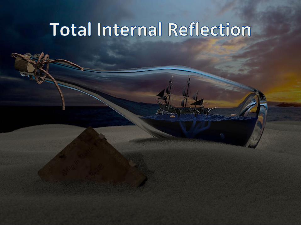
Total Internal Reflection• When light goes from a material with a higher refraction index (n2) to a material
with a lower refraction index (n1), there is no refraction/transmission when the incident angle exceeds a critical angle (in this case, all the light reflects)
when θ2 < θ2,max , both refraction/transmission and reflection
when θ2 > θ2,max , only reflection 23

Critical Angle• Compute the critical angle using Snell’s Law:• Assume , then
24
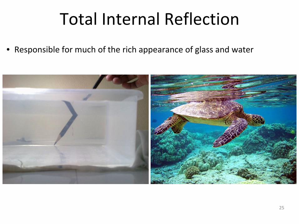
Total Internal Reflection• Responsible for much of the rich appearance of glass and water
25

Snell’s Window
26

Snell’s Window
http://en.wikipedia.org/wiki/Snell’s_window
27

28

Reflection vs. Transmission • The proportion of reflection versus transmission gradually increases as the
viewing angle goes from perpendicular to a parallel (grazing)
Perpendicular view:high transmission, low reflection
Parallel (grazing) view:high reflection, low transmission 29

Reflection vs. Transmission
[Lafortune et al. 1997]
30
• Reflection similarly increases for non-transparent (opaque) objects as the viewing direction becomes more parallel/grazing
• Notice the increase in reflectivity of the table from left to right

Fresnel Equations• Light can be polarized into 2 parts based on whether the plane containing the
incident, reflected, and refracted rays is parallel or perpendicular to the electric field of the light
• We denote the light as p-polarized if it is parallel and by s-polarized if it is perpendicular (to the electric field)
• The Fresnel equations give the fraction of light reflected off the interface between two materials as:
• It is assumed that any light which is not reflected is instead transmitted through the interface from one material to the other, so:
• For unpolarized light (a typical assumption in ray tracing), the overall reflection and transmission coefficients are assumed to be:
31

Fresnel Equations
Light entering a denser material,e.g. from air into water
Light leaving a denser material,e.g. from water into air
32

33

Conductors vs. Dielectrics• Conductors
– Objects that conduct electricity (e.g. metal)– Have reflection and absorption, but no transmission
• Dielectrics– Objects that don’t conduct electricity (e.g. glass)– Have both reflection and transmission
DielectricConductorhttp://renderman.pixar.com/resources/current/rms/tutorialRayTracing.html
34

Conductors• Conductors don’t transmit light• Most of the incident light is reflected, and some of it is absorbed
– The reflection term changes relatively slowly with the incident angle (as compared to dielectric materials)
• E.g., for aluminum, the reflection changes from about 90% to 100% as the incident angle changes from 0o to 90o
• Can typically treat kr as a constant independent of viewing direction (and kt = 0)
http://www.raytracing.co.uk/http://download.autodesk.comRay traced conductors
35

Question 3List 5 conductors

Dielectrics
37
• Strongly depend on the Fresnel equations to get the proper reflection vs. transmission of light based on viewing angle

Schlick’s Approximation• Approximates the reflection term in the Fresnel Equation as:
• R0 controls the Fresnel reflections of different materials– R0 ranges from 0 to 1– Reference values are available for many real-world materials– Same equation can be used for both dielectrics and conductors
38
where
R(θi) part of light is reflected
1-R(θi) part of light is refracted or absorbed

Schlick’s Approximation
Schlick’s approximation (dotted lines) compared to the Fresnel equations (solid lines)39

Question 4List 5 dielectrics

41

Attenuation• Light is attenuated as it travels through media• The attenuation effect from the media is stronger over longer
distances• Different colors attenuate with different rates
– Shallow water is clear (almost no attenuation)– Deeper water attenuates all the red light and looks blue-green– Even deeper water also attenuates all the green light and looks
blue– Eventually all the light attenuates, and the color ranges from
blackish-blue to black
42

Beer’s Law• If the media is homogeneous, the attenuation along the ray can be described using
Beer’s Law:
where I is the light intensity, x is the distance along the ray, and c is the attenuation constant (which varies based on color/wavelength)
• Solving this Ordinary Differential Equation (ODE) with the initial value results in:
43

Beer’s Law
The color of a transparent object can be described by three independent attenuation components for the three color channels (R, G, B)
44

Question 5List 5 objects that attenuate light

46

Atmospheric Refraction• Light is bent into a curved path when it passes through the atmosphere • Happens continuously, not just at an interface• This is due to the continuous variations in air density, and thus continuous
variations in the refractive index
• Inferior mirage - the mirage is located under the real object• Superior mirage - the mirage is located above the real object
http://science-at-home.org/mirages/
47

Inferior Mirage
Credit: Brocken Inaglory
48
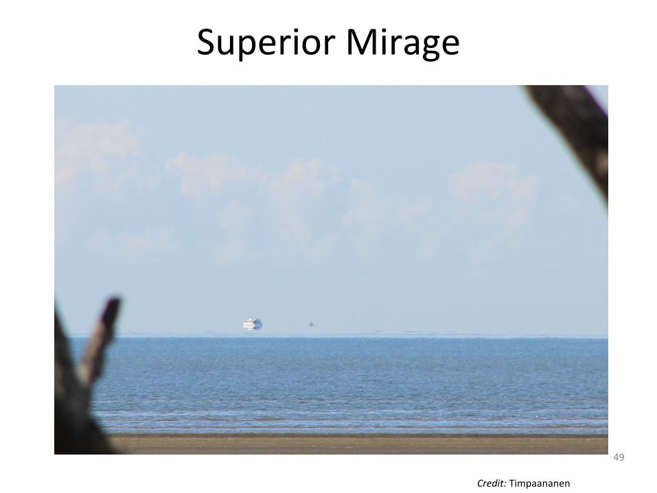
Superior Mirage
Credit: Timpaananen
49

Ray Tracing Mirages• Bend the rays as they go through varying air densities• Change the light direction between every interval in the vertical
direction or along the ray direction
50

Ray Tracing Mirages
by Itai Katz and Pankhudi
51

Ray Tracing Curved Paths
52
http://www.wired.com/2014/10/astrophysics-interstellar-black-hole/http://news.discovery.com/space/interstellar-black-hole-is-best-black-hole-in-sci-fi-141029.htm

Extra CreditList two distinct causes for the bending of light

54

Iridescence
55
• Color of light changes with the viewing direction

Iridescence
56
• Various light waves are emitted in the same direction giving constructive and destructive interference
http://www.glassner.com/wp-content/uploads/2014/04/CG-CGA-PDF-00-11-Soap-Bubbles-2-Nov00.pdf

Take Home Extra CreditList 10 iridescent objects