Embed Size (px)
Citation preview

Reforming the Energy Vision (REV)
Working Group II: Platform Technology
Table of Contents
Executive Summary ............................................................................................................................ 2
Body of Report ................................................................................................................................... 4
Subgroup: Existing Utility Distribution Systems and Capabilities .............................................................. 5
Iberdrola USA (NYSEG and RG&E)............................................................................................................. 5
National Grid ............................................................................................................................................ 17
Central Hudson ........................................................................................................................................ 27
Consolidated Edison ................................................................................................................................ 42
Subgroup: Platform Functionalities ......................................................................................................... 56
Subgroup: Standards & Protocols ............................................................................................................ 75
Subgroup: Technologies ........................................................................................................................ 110
Appendices: ............................................................................................................................................. 127
Appendix A: Full List of Working Group & Subgroup Members............................................................ 128
Appendix B: Draft of Functions to Policy Mapping Tool – Preliminary in Nature ................................. 135
Appendix C: Draft Use Cases – Preliminary in Nature .......................................................................... 138
Dynamic Electricity Production Forecasting ......................................................................................... 139
Direct Load Control .............................................................................................................................. 153
Volt VAR Optimization .......................................................................................................................... 197
Appendix D: P2030 Conceptual Architectural Diagrams....................................................................... 209
Appendix E: Draft of Technology Matrix Mapping Tool – Preliminary in Nature ................................. 222
1

Working Group II Platform Technology Executive Summary July 8, 2014
I. Executive Summary
a. Who We Are: Working Group II: Platform Technology was formed on May 12, 2014 at the Reforming the Energy Vision (REV) Collaborative Meeting. The Working Group consisted of over 70 organizations and approximately 140 individuals representing a broad cross section of interested parties and DPS Staff.1 The Working Group Co-Convenors were Michael Rieder and Peggie Neville, DPS Staff; David Lovelady, Siemens PTI; Brian Horton, Consolidated Edison Company of NY; and Jim Gallagher, NY Smart Grid Consortium. The Working Group identified four specific areas of focus. Volunteers from the full Working Group were sought to form these subgroups to research and compile information on the specific areas of focus and present back to the full Working Group. The Subgroups2 and their respective leads were:
i. Existing Utility Distribution Systems and Capabilities, Brian Horton, Con Edison ii. Platform Functionalities – Laney Brown, Iberdrola USA
iii. Standards & Protocols – David Lovelady, Siemens PTI iv. Platform Technologies – John D’Aloia, DPS
The Working Group held 7 meetings from May 14 through June 25, with several subgroup meetings throughout this timeframe.
b. What we set out to do:
The objective of Working Group II: Platform Technology was to identify the infrastructure and technology needed to enable the Distributed System Platform Provider (DSPP) to integrate, monitor, and control Distributed Energy Resources (DER), while:
• Ensuring system reliability; • Increasing system resiliency and efficiency; • Maintaining system security; • Maximizing energy efficiency; • Promoting fuel diversity; and • Empowering customer choice and third party participation in newly-formed
markets.
c. Key Findings i. The utilities have been planning and deploying technologies that will improve system
visibility, enhance control and support analytics that can help achieve objectives described in REV.
ii. New York can build on advancements being made in advanced grid technology and the support of DER around the world by utilities and industry leaders.
iii. The REV process is an opportunity to align ongoing utility activity with a larger vision for New York.
iv. It is important to have clear ‘line of sight’ from policy goals to functionality to technology investments.
1 A full listing of Working Group Members is included in Appendix A. 2 A full listing of Subgroup Members is included in Appendix A.
2

v. The DSPP functionalities will evolve as technology and markets evolve and there is an increased penetration of DER.
vi. A number of well defined Standards and Protocols exist that will support the DSPP. vii. Standards and Protocols support wide-scale DER integration, customer participation,
market transactions and operational control. viii. The data, security and integration complexity of a DSPP requires the rigor of a
structured architecture. ix. A number of technologies exist, in various stages of maturity, that can support
anticipated functions of the DSPP. However, an ‘off-the-shelf’ comprehensive platform system does not currently exist.
x. Each DSPP will need to consider the existing utility distribution systems and capabilities in identifying the technologies needed to allow the DSPP to evolve.
xi. Defining and mapping the enabling technologies to the DSPP platform functions provides a common approach to assess the variety of evolving technologies while
1. Creating a structure to identify functionalities and technology capabilities over time, and
2. Identifying the technologies and gaps existing today. xii. Key considerations for the development of DSPP platform technologies include:
1. Designing in cyber security; 2. Assuring interoperability and consistency across DSPPs; and 3. Supporting future flexibility and scalability.
3

Body of Report
The full power points presented to the Working Group.
4

Existing Utility
Distribution Systems and Capabilities
Iberdrola USA (NYSEG and RG&E)
5

NYSEG & RGE Energy Control Systems
NYS DPS Platform Technology Working Group
May 28, 2014
6

2
Iberdrola USA Foundational Systems for the Modern Grid
Energy Control Systems • Provides centralized real time control and monitor across the entire
grid
Substations • Remote engineering access and support for modernized, automated
substations
AMI • Enables real time visibility and control up to and beyond the meter
with significantly greater granularity and frequency than today
7

3
NYSEG and RG&E Energy Control Systems
Integrated Control Solution for New York • A single integrated control center platform for NYSEG and RG&E
• Alignment with IBERDROLA global standards & practices
• Full integration of key components (SAP, GIS, DMS, TMS, OMS)
• Full compliance with all FERC and NERC requirements
• Reengineering of systems and processes to become “Best in Class”
• Prepare for increased automation on the network
• Facilitate centralization of operations
• Provide customer facing services for outage management
ACRONYMS GIS- Geographic Information System DMS- Distribution Management System TMS- Transmission Management System OMS- Outage Management System
8

4
NYSEG and RG&E Energy Control Systems
ACRONYMS GIS- Geographic Information System DMS- Distribution Management System TMS- Transmission Management System OMS- Outage Management System
9

5
NYSEG and RG&E Energy Control Systems The Integration of the EMS/SCADA system with the OMS provides real time transmission, substation, and distribution situational awareness.
Benefits OMS dispatchers and operators • Improves the identification of interrupted equipment/circuits • Decreases outage restoration times • Improves accuracy of outage analysis engine • Increases general public and utility crew safety
Supports substation and distribution automation • Capability to monitor many more data points • Simplifies new RTU additions
Corporate GIS Integration • Outage maps on the internet • Customer data available to OMS operators and dispatchers • Decrease data entry errors and database reconciliation delays
Improved Efficiencies • Single system upgrade covers both companies • Accommodates FERC /NERC requirements
10
6
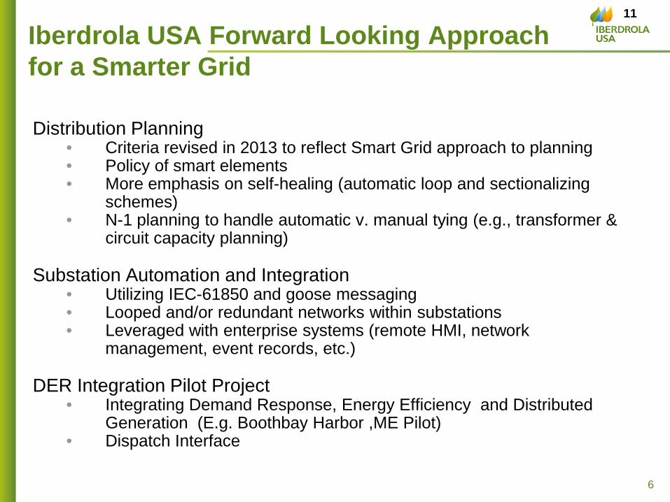
Iberdrola USA Forward Looking Approach for a Smarter Grid
Distribution Planning • Criteria revised in 2013 to reflect Smart Grid approach to planning • Policy of smart elements • More emphasis on self-healing (automatic loop and sectionalizing
schemes) • N-1 planning to handle automatic v. manual tying (e.g., transformer &
circuit capacity planning) Substation Automation and Integration
• Utilizing IEC-61850 and goose messaging • Looped and/or redundant networks within substations • Leveraged with enterprise systems (remote HMI, network
management, event records, etc.)
DER Integration Pilot Project • Integrating Demand Response, Energy Efficiency and Distributed
Generation (E.g. Boothbay Harbor ,ME Pilot) • Dispatch Interface
11

7
IUSA Substation Automation & Integration Design
System A Relays
System B Relays
SCU
HMI
Local Firewall
Event Records Secure Access Digital
Substation Database
Primary Energy Management
System Remote HMI Network
Monitoring
Authentication Servers
Secondary Energy Management
System
Synchrophasors Enterprise Firewall(s)
RTU
PDC (If Required)
OT LAN Network Switches
Enterprise Systems
Substations
12

8
Central Maine Power’s AMI – OMS Integration
Increased outage visibility and restoration • OMS captures and displays meter-level outage
information in near real time • Meter events clear outage work orders • Meter ‘pings’ determine power status for efficient
restoration efforts
Faster assessment and restoration • 7 X more AMI events than customer calls for more
accurate outage assessment • On average, meter events come in 10 minutes faster
than the first customer calls • More efficient restoration to clear nested outages
with meter pings
Aclara Settlement
Billing System
Energy Portal
AMI Head End
System
Itron MDMS
AMI Secure Mesh Network
OMS
Work Management
System
GIS
13

9
AMI Meter Off Events During an Outage 14

10
AMI Events and Power Restoration
Ping Option
15

11
NY Energy Control Systems Centralized real time control and monitor across the entire grid Substation Automation Advanced operation and automated control of substation assets
Iberdrola USA Support DSPP Foundations
DSPP
Regulator
Markets
Customer
System
Maine’s AMI System Near real time visibility and control up to and beyond the meter Distribution Automation Intelligence and control of distribution segments
The experience and the investments across Iberdrola USA will be foundational for the DSPP
16

Existing Utility
Distribution Systems and Capabilities
National Grid
17

Progressing towards the DSPP
May 28, 2014
18

The Foundation for the Platform
SCADA on only 52% of substations
Areas of low customer density
> 50% of Distribution Line miles are 5kV
Radial design with limited Feeder Ties
Limited communications to field devices.
19

Energy and Outage Management System (EMS & OMS)
Upgrading existing EMS and OMS systems to ABB Network Manager Initial benefits of the common Network Manager platform:
Real time transfer of grid device status from EMS to OMS for optimization of outage prediction.
Integration of telemetered analog data from EMS to OMS to enhance situational awareness .
Provides a common platform to leverage future capabilities.
e.g., Volt VAR Optimization, Unbalanced Load Flow, Advanced Metering Infrastructure, Restoration Switching Analysis.
Current forecasted go-live dates are:
NY EMS late 2014
NY OMS 2nd half 2015
3
20

21

22
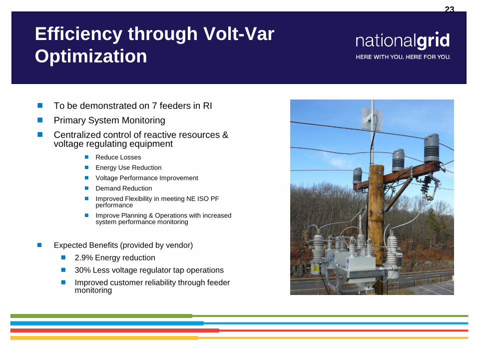
Efficiency through Volt-Var Optimization
To be demonstrated on 7 feeders in RI Primary System Monitoring Centralized control of reactive resources &
voltage regulating equipment Reduce Losses Energy Use Reduction Voltage Performance Improvement Demand Reduction Improved Flexibility in meeting NE ISO PF
performance Improve Planning & Operations with increased
system performance monitoring
Expected Benefits (provided by vendor)
2.9% Energy reduction 30% Less voltage regulator tap operations Improved customer reliability through feeder
monitoring
23

DG Interconnections
DG applications are increasing and the MW size of requests are also increasing.
Anti-islanding protection via Direct Transfer Trip can be expensive and restrictive for circuit re-configuration
New technology being evaluated in Potsdam.
Other enabling efforts: The Fraunhofer Plug & Play Team
DOE-FOA-479 Smart-Grid Ready PV Inverter with Utility Communication
24

Microgrids
Potsdam Resiliency Based Multiple generators Multiple loads Resilient UG interconnections
Buffalo Niagara Medical Campus Realistic optimization
possibilities for power quality and energy efficiency will be identified throughout the power grid as well as within BNMC customer facilities.
25

Non-Wires Alternatives
Consideration of DER as a deferral option to traditional utility infrastructure expansion.
Custom Solutions: T&D Planning Engineers working closely with Customer EE and DR teams.
Initial Efforts
Tiverton, RI
Nantucket, MA
Brockport, NY
26

Existing Utility
Distribution Systems and Capabilities
Central Hudson
27

Smart Grid and Integrated Communication Strategy
28

Overall Goals/Key Strategic Components
Strategic Components Distribution Management System (DMS/ADMS) Intelligent devices/sensors Integrated Communication System
DMS Infrastructure IEDs Communications
Goals Improve Grid Efficiency Better Utilization of Existing Assets Enhanced Resiliency Allow for greater penetration of DER
29

Distribution Management System • Key Objectives:
– Develop an integrated near real time system model for the distribution system which enables 24/7/365 system optimization
– Create an operator workstation to practically manage data – Integrate the transmission system to understand how the T&D
systems are interrelated – Develop solar analysis tools – Further develop capabilities to model/integrate DER
DMS Infrastructure IEDs Communications
30

Dew - ISM
Dew Data Base (Part Definitions)
(Access, Oracle, etc.)
Dew Circuit Server (Circuit Files)
GIS GE via Red
Planet
OMS GE Small World
OMS
EMS GE XA21
SCADA Telemetric
GE Historian EDNA
CIS Small Cust kWHR
MV90 Large Cust Load
Load Research
Weather
* Note EDNA includes SCADA Data
*
*
Integrated System Model developed for PON 1913 Pilot Area
DMS Infrastructure IEDs Communications
4 Distribution Circuits Modeled
at High Falls Substation
31

Solar Analysis Tool becoming more Important
DMS Infrastructure IEDs Communications
0
2
4
6
8
10
12
14
16
Cumulative Solar MW by Year
Installed Projected
Metering (as of 10/23/13) # Installations MW Completed 1532 14.1
Pending 269 6.2
32
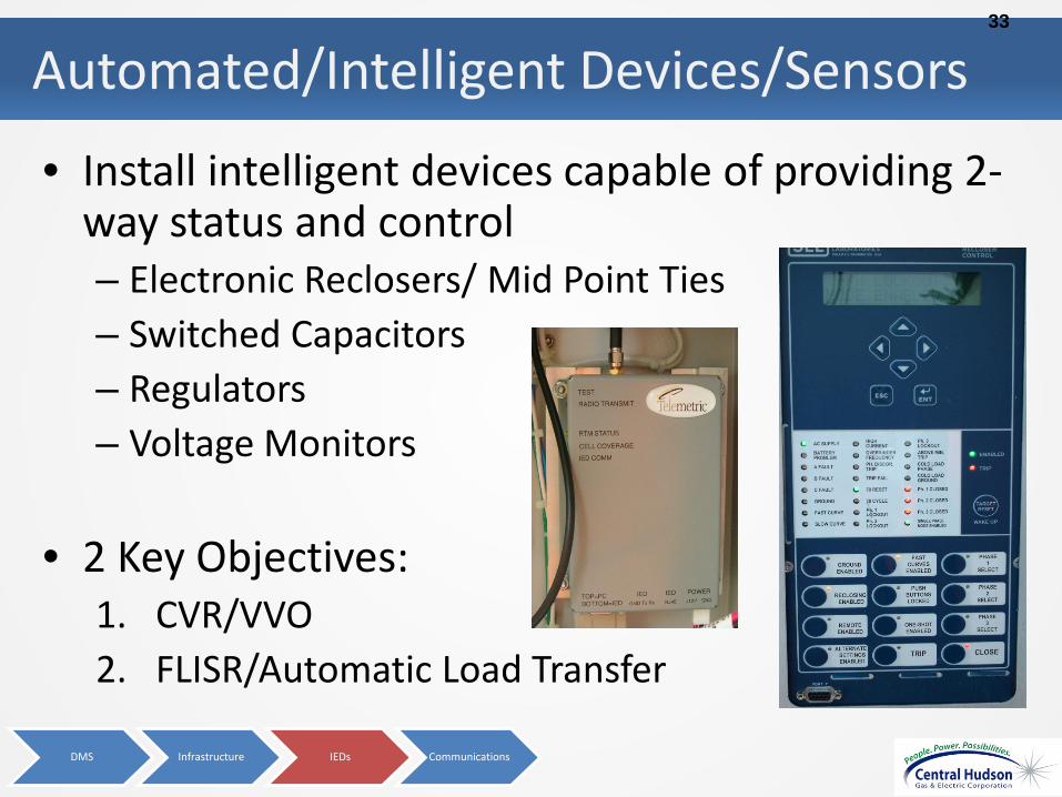
Automated/Intelligent Devices/Sensors
• Install intelligent devices capable of providing 2-way status and control – Electronic Reclosers/ Mid Point Ties – Switched Capacitors – Regulators – Voltage Monitors
• 2 Key Objectives: 1. CVR/VVO 2. FLISR/Automatic Load Transfer
DMS Infrastructure IEDs Communications
33

CVR: Trial resulted in 2.50% kW reduction • Trial Project: High Falls 3022 Circuit using a regulator
feeding a resort – 3% voltage reduction 2.50% kW reduction for the
customer – 11 months of day on vs. day off testing – DEW also analyzed phase balancing and capacitor
placement
• 2nd Trial began in May: Lincoln Park 2016 – Good load mix
• 1049 customers • 21 3-phase customers
DMS Infrastructure IEDs
CVR
ALTs
Communications
34

CVR: Average Load Profile with and without
DMS Infrastructure IEDs
CVR
ALTs
Communications
35

CVR: Next Steps • Transition from testing feeder “Pockets” to testing
CVR on entire feeder – 3 feeders are planned for CVR testing – Models will need to be created to determine if there will
be any adverse customer impacts with a 3% voltage reduction
– E.O.L. voltage monitors will be installed in order to insure we stay within ANSI standards
• Complete M&V on summer data to determine
correlation between feeder composition and CVR factor
DMS Infrastructure IEDs
CVR
ALTs
Communications
36

The New Automatic Load Transfer (“ALT”) • Radial 69 kV transmission feed
in Woodstock, NY to 8,245 customers
• Automatic Transfer using electronic recloser loop schemes
• Demonstrate deferral of capital investments (Spend $1 million to defer $15 million)
• 2-way communications/control via the DMS (future)
10
• NYSERDA PON 2474
DMS Infrastructure IEDs
CVR
ALTs
Communications
37

Integrated Communication Strategy
DMS Infrastructure IEDs Communications
Cross-Functional Team Considered Benefits beyond DA
SCADA Distribution Automation Meter Reading (large customer) Voice Data from field devices Transmission Line Protection Security (video and card access) Links to Radio Towers Meter Reading (residential – future)
Distribution Automation
38

Integrated Communication System Diagram
Proposed Architecture
High-Speed
Central Data Center
SubStat
DistrictOffice
DSCADA
SubStat
SubStat
SubStat
SubStat
Medium-Speed
Low-Speed
Multi-Tier NetworkBackbone
DMS Infrastructure IEDs Communications
39
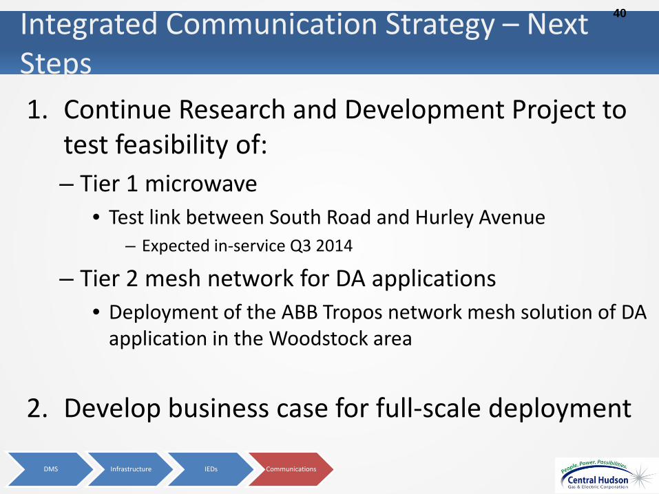
Integrated Communication Strategy – Next Steps 1. Continue Research and Development Project to
test feasibility of: – Tier 1 microwave
• Test link between South Road and Hurley Avenue – Expected in-service Q3 2014
– Tier 2 mesh network for DA applications • Deployment of the ABB Tropos network mesh solution of DA
application in the Woodstock area
2. Develop business case for full-scale deployment
DMS Infrastructure IEDs Communications
40

The Future Vision for Distribution: 2015 - 2020
• ESRI is the data center
• Centralized Distribution Automation through DMS
• Defer substation and transmission capital expenditures – Distribution infrastructure
upgrades – Automated ties – Conservation Voltage
Reduction
• Currently over 5-7 years
ESRI
OMS
DMS
DEW (Modeling)
Inspections and Repairs
Asset Data
Estimating Drawings
41
Existing Utility
Distribution Systems and Capabilities
Consolidated Edison
42

1
Con Edison Demonstration Project DE-OE0000197
Customer Sited Resource Management Tools
43

2
DERMS
• Distributed Energy Resource Management System – Siemens/TIBCO
• Demand Response & Distributed Generation resources integrated with distributed system
• Near real time status of DR and DG resources
• Control Capability: Demonstrated control of DR Resources via secure messages through NOC or directly to buildings (disabled initially)
• User Group – Distribution Engineering
DRMS
• Demand Response Management System – Alstom Grid
• Demand Response Program Management – Enroll – Event notification – CBL performance – Reporting – Settlement
• Near real time DR performance • User Group – Energy Efficiency
44

3
Distributed Energy Resource Management System (DERMS)
Smart Grid Data Store
Load Flow
Interval Meters
Smart Meters
One Line Displays
Tabular Displays
Impact Analysis
Meter Data Processing
Demand Response
Complex Event Processing SOA Adapter SOA Adapter
Substation/Feeders/
Transformer Status
SOA Adapter SOA Adapter
SOA Adapter
SOA Adapter
SOA Adapter
SGDP Secure Interoperable Services
Distributed Energy
Resources/ Demand
Response Participants
SOA Adapter
SOA Adapter
SOA Adapter
Con Edison DERMS Others
Logging Alerts Management/Monitoring Notification
45

4
Distributed Energy Resource Management System
• Con Edison Distributed System Status integrated with Customer Resources
• Targeted Demand Response from the following: – Building Management System (BMS)
– Controller Connected to Standby Diesel Generator
– Controller Connected to Electric Vehicle Charger with Standby Battery and PV Generation
– ThinkEco Modlets DR resource mapping
46

5
DERMS Resource Information
• Resource type
• Available Demand Response
• Current Generation
• Current Load Drawn
• Date / time of last status
47
6
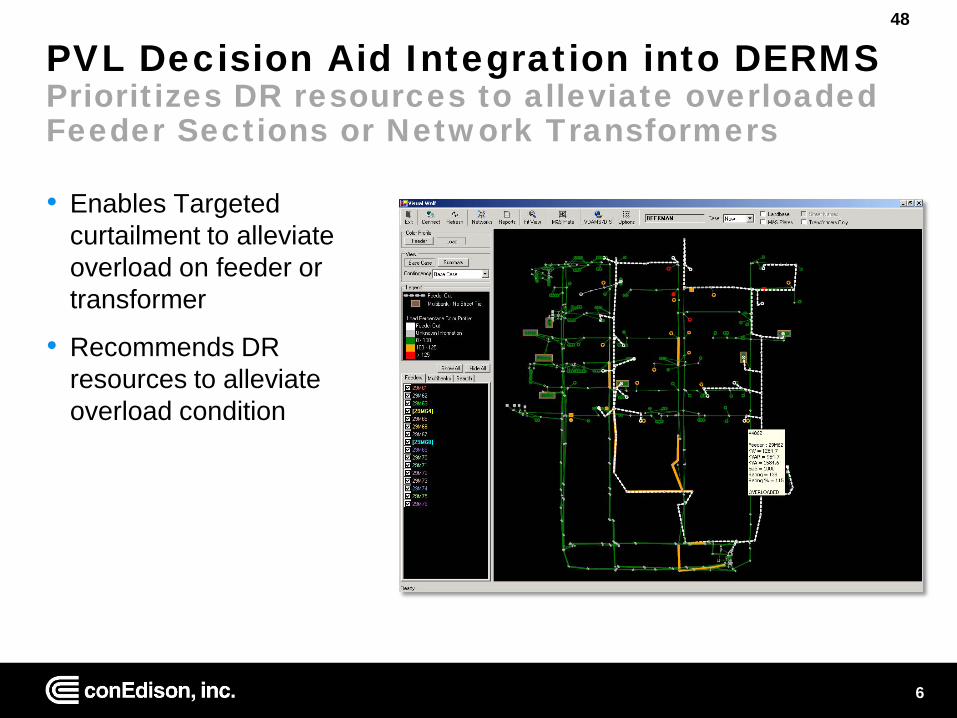
PVL Decision Aid Integration into DERMS Prioritizes DR resources to alleviate overloaded Feeder Sections or Network Transformers
• Enables Targeted curtailment to alleviate overload on feeder or transformer
• Recommends DR resources to alleviate overload condition
48

7
SGDP Demand Response Diagram
SGDP Demand Response protocols provide better visibility and real-time dispatch of customer resources
Status Status
Curtailment Action
Start Curtailment Message
Lexington Ave DR:100 kW
Software
Distribution Control Center
Demand response
Distributed generation
28 Facilities with 20 MW of DG
49

8
DERMS
• Distributed Energy Resource Management System – Siemens/TIBCO
• Demand Response & Distributed Generation resources integrated with distributed system
• Near real time status of DR and DG resources
• Control Capability: Demonstrated control of DR Resources via secure messages through NOC or directly to buildings (disabled initially)
• User Group – Distribution Engineering
DRMS
• Demand Response Management System – Alstom Grid
• Demand Response Program Management – Enroll – Event notification – CBL performance – Reporting – Settlement
• Near real time DR performance • User Group – Energy Efficiency
50
9
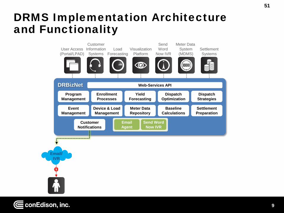
DRMS Implementation Architecture and Functionality
Program Management
Enrollment Processes
Yield Forecasting
Dispatch Optimization
Dispatch Strategies
Device & Load Management
Event Management
Meter Data Repository
Baseline Calculations
Settlement Preparation
DRBizNet Web-Services API
Email/ IVR
User Access (Portal/LPAD)
Load Forecasting
Meter Data System (MDMS)
Settlement Systems
Customer Information
Systems Visualization
Platform
Send Word
Now IVR
Customer Notifications
Email Agent
Send Word Now IVR
51

10
Baseline Calculations
Baseline Calculations Engine
• Calculates recent historical usage to determine average usage prior to an event
• Calculates the actual performance during a DR event
Settlements Preparations Engine
• Calculates the payment due to a customer based upon their performance and the Program payment rules
• Calculates each hour / time segment separately
• Submits the credit/payment as a billing determinant to the Billing system
52

11
Visualization of Pre-defined Event Strategies Impact shown against the system load
53

12
Optimization Module Modeling Dispatch Options
• Targeted DR Reduction
• Peak Load Shifting
• Economic Pricing/Profit
54

13
Con Edison Demonstration Project DE-OE0000197
Customer Sited Resource Management Tools
55

Platform Functionalities
56

NYSDPS
WG-2: Platform Technology Functionality
New York State Department of Public Service
DRAFT 06-30-2014
57

DRAFT 06-23-2014 WG-2: Platform Technology Page 2
Agenda
2
1 Development Approach
2 Definition, Scope and Role
3 High Level Functionality
4 Next Steps
58

DRAFT 06-23-2014 WG-2: Platform Technology Page 3
Agenda
3
1 Development Approach
2 Definition, Scope and Role
3 High Level Functionality
4 Next Steps
59

DRAFT 06-23-2014 WG-2: Platform Technology Page 4
• Ecosystem, Scope and Role • Key Linkages
• Policy objectives • Required functionality • Enabling technologies and infrastructure • Products, services and pricing
• Impacts/Outcomes • Benefits
Framework Components
4
60

DRAFT 06-23-2014 WG-2: Platform Technology Page 5
PTWG Guiding Principles
5
Source: Working Outline, Platform Technology Working Group, June 2, 2014
Technology Focused • Interoperable and standards based • Consumer data privacy secured • Meet /Exceed Federal & State Cyber Security
requirements • Enable transparent mechanism for technology
updates through new regulatory tracking and accounting rules
• Promote greater visibility/control on the grid. • Encourage open system architectures to
maximize customer/third party participation (open architecture)
• Encourage platform standardization across utility service areas (standard interfaces)
• Achieve desired functionality while minimizing costs
• Minimize risk of obsolescence while optimizing new technologies/functionalities
• Employ scalable and flexible technologies
Policy Focused • Enable significant expansion of customer
facing energy services (all classes) • Promote greater and more efficient use of
DER including microgrids • Maximize efficiency of existing utility
infrastructure • Enable transparent market based
customer participation to grid reliability (Capacity) and differentiated energy delivery (Energy Source).
• Promote retail level markets and entry of new retail energy service providers
• Promote the development of net-zero and grid-integrated premises and develop mechanism to interact with them through the delivery of other services to them.
• Ensure continued system reliability, resilience, and security
61

DRAFT 06-23-2014 WG-2: Platform Technology Page 6
Platform Functionalities DSPP Objectives
Market Operations
• Rich information for consumers and suppliers
• Diverse technologies, products and services
• Transparency , flexibility, and efficiency
Grid Operations
• Secure, reliable and resilience
• Flexible and dynamic • Economical and energy
efficient
Integrated System
Planning
• Diverse and distributed energy resources
• Coordination with bulk system
• Integration with market and operations drivers
DSPP
62

DRAFT 06-23-2014 WG-2: Platform Technology Page 7
Agenda
7
1 Development Approach
2 Definition, Scope and Role
3 High Level Functionality
4 Next Steps
63

DRAFT 06-23-2014 WG-2: Platform Technology Page 8
Platform Functionalities Working Definition of the DSPP
Working Definition of DSPP: The DSPP operates an intelligent network platform that will provide safe, reliable and efficient electric services by integrating diverse resources to meet customers’ and society’s evolving needs. The DSPP fosters broad market activity by enabling active customer and third party engagement that is aligned with the wholesale market and bulk power system.
64
DRAFT 06-23-2014 WG-2: Platform Technology Page 9
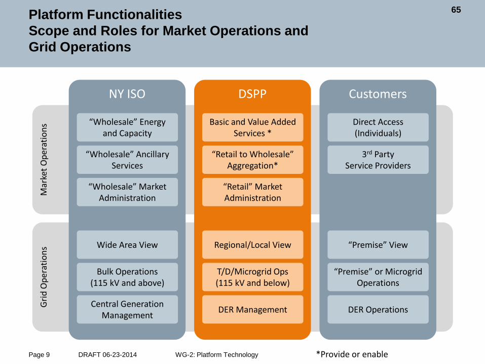
Platform Functionalities Scope and Roles for Market Operations and Grid Operations
• Fuel and resource diversity • System reliability • Reduced carbon emissions
Grid
Ope
ratio
ns
Mar
ket O
pera
tions
NY ISO DSPP Customers
“Wholesale” Energy and Capacity
“Wholesale” Market Administration
Basic and Value Added Services *
Wide Area View
Bulk Operations (115 kV and above)
“Wholesale” Ancillary Services
“Retail to Wholesale” Aggregation*
Regional/Local View
T/D/Microgrid Ops (115 kV and below)
“Retail” Market Administration
Central Generation Management DER Management
Direct Access (Individuals)
3rd Party Service Providers
“Premise” View
DER Operations
“Premise” or Microgrid Operations
*Provide or enable
65

DRAFT 06-23-2014 WG-2: Platform Technology Page 10
Platform Functionalities DSPP Scope and Role for Integrated System Planning
NYISO
Customer or ESP
Bulk Generation
Transmission
Substation
Distribution Primary
Distribution Secondary
Customer Meter
Cust
omer
Ap
plia
nce
Cust
omer
M
icro
grid
DG a
nd
Stor
age
NYISO
DSPP
Customer or ESP
DSPP Integrated Planning Analytics
DER Production Data Load Data
Bulk Generation Forecasts
T&D Upgrades T&D Maintenance
Ancillary Services Needs
New Connections
Bulk System Upgrades
Supply/Demand Planning
Electric Network Levels Integrated System Planning
66

DRAFT 06-23-2014 WG-2: Platform Technology Page 11
Agenda
11
1 Development Approach
2 Definition, Scope and Role
3 High Level Functionality
4 Next Steps
67

DRAFT 06-23-2014 WG-2: Platform Technology Page 12
Platform Functionalities Preliminary DSPP functionalities in key areas
• Real-time load monitoring • Real-time network monitoring • Adaptive protection • Enhanced fault
detection/location • Outage/restoration notification • Automated feeder and line
switching (FLISR/FDIR) • Automated voltage and VAR
control • Real-time load transfer • Dynamic capability rating • Power flow control • Automated islanding and
reconnection (microgrid) • Real time/predicted
probabilistic based area substation, feeder, and customer level reliability metrics (MTTF/MTTR
• Direct load control • DER power control • DER power factor control • Automated islanding and
reconnection • Algorithms and analytics
for Customer/DER/Microgrid control and optimization
• Dynamic event notification • Dynamic pricing • Market-based demand
response • Dynamic electricity
production forecasting • Dynamic electricity
consumption forecasting • M&V for producers and
consumers (premise/appliance/resource)
• Participant registration and relationship management
• Confirmation and settlement • Billing, receiving and cash
management • Free-market trading • Algorithms and analytics for
market information/ops
Grid Customer/DER/
Microgrid Market
Enable
68

DRAFT 06-23-2014 WG-2: Platform Technology Page 13
Platform Functionalities DSPP Enablement of Policy Objectives
REV Policy Objective DSPP Enables
Customer knowledge and tools that support effective management of their total energy bill
YES
Market animation and leverage of ratepayer contributions
YES
System wide efficiency YES Fuel and resource diversity YES System reliability and resiliency YES Reduction of carbon emissions YES
69

DRAFT 06-23-2014 WG-2: Platform Technology Page 14
Grid Example
14
70

DRAFT 06-23-2014 WG-2: Platform Technology Page 15
Customer/DER/Microgrid Example
15
71

DRAFT 06-23-2014 WG-2: Platform Technology Page 16
Market Functionality Example
16
72

DRAFT 06-23-2014 WG-2: Platform Technology Page 17
Agenda
17
1 Development Approach
2 Definition, Scope and Role
3 High Level Functionality
4 Next Steps
73
DRAFT 06-23-2014 WG-2: Platform Technology Page 18
• Complete mapping of framework linkages including policy objectives, functional requirements, enabling technologies and infrastructure, impacts and benefits
• Complete high level technology architecture • Align input from Products and Services working on platform functional
requirements
Next Steps
18
74

Standards & Protocols
75

XX-XX-2014 Page 1
NYSDPS
Standards and Protocols Subgroup
NYS DPS - Platform Technology Working Group
76

XX-XX-2014 Page 2
Members of the Working Subgroup
Subgroup Lead - David Lovelady (Siemens PTI), [email protected] Tony Abate (NYSERDA), [email protected] Deana Dennis (NEMA), [email protected] Jim Gallagher (Smart Grid Consortium), [email protected] Marty Uczen (Verizon), [email protected] Mike Williams (Staff), [email protected] Tom Herbst (Silver Springs), [email protected] David Locke (Verizon), [email protected] Michael Vecchi (Landis & Gyr), [email protected] Dr Mani Vadari (NY State Consortium), [email protected] Robert Sheridan (National Grid), [email protected] EPRI Arindam Maitra, [email protected] Tom Short, [email protected] Becky Wingenroth, [email protected]
77

XX-XX-2014 Page 3
Members of the Working Subgroup
LBNL Girish Ghatikar, [email protected] Peter Cappers, [email protected] Sila Kiliccote, [email protected] Staff Michael Rieder, [email protected] Peggie Neville, [email protected]
78

XX-XX-2014 Page 4
Contents
1. Introduction. 2. SP Background. 3. DSPP SP Framework. 4. Industry leading SP. 5. The current use of SP in NY. 6. Gaps in SP relevant to SP. 7. Conclusions & Suggestions. 8. References.
79

XX-XX-2014 Page 5
Introduction
The mains aim of this document is not to detail each and every SP relevant to the DSPP (although they are provided as an appendix) but instead highlight several topics this WG felt important for NYSPSC staff. Please note, there are many SP that are not directly mentioned in this document and the discussion is based on the current knowledge of the limited number of working group members. “Successful, market driven technologies will also require interoperability, connectivity and open standards” – REV “An important step to encourage aggregation is for the Commission to establish protocols and standards for accessing and sharing customer information”. - REV As specified in REV, for successful implementation of the DSPP, SP will be very important in particular to ensure interoperability for the public benefit.
80

XX-XX-2014 Page 6
SP Background
• Smart grid SP are fragmented and confusing. • Not only are there multiple named and numbered SP from multiple SP bodies (IEC, IEEE, ANSI, OAG, OpenSG and so on) dealing with the same issues, but there are also multiple SP bodies engaged in sometimes overlapping, sometimes complementary, efforts. • In order to address some of the complexity NIST Smart Grid Interoperability Panel are charged with indentifying applicable standards, identifying gaps and driving new SP to cut across the current sea of SP.
81

XX-XX-2014 Page 7
SP Background Con’t
• There are several layers of SP for example an SP for the data representation, a SP for the data structure with the IT system, a SP for the communication protocol and a SP for the hardware I/O (inputs & outputs). • From history of other SP developments it is understood several industry SP will end up as popular solutions for each layer and to wait for completion of the optimal SP before implementing smart grid could be a very long wait. • For SP development there is usually a race between vendor developed SP and committee SP, the winners will be determined by the industry as a whole over time.
82
XX-XX-2014 Page 8
Framework
• To identify relevant industry Standards and Protocols (“SP”) applicable to the DSPP. • Includes distributed and customer sited resources but not intra-building, DER technology specific, or internal operations of distribution or ISO operations. • The pertinent SP will support resources integration for program participation, transactions and operational control as necessary.
83
XX-XX-2014 Page 9 9
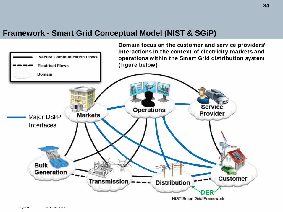
Framework - Smart Grid Conceptual Model (NIST & SGiP) Domain focus on the customer and service providers’ interactions in the context of electricity markets and operations within the Smart Grid distribution system (figure below).
Major DSPP Interfaces
DER
84

XX-XX-2014 Page 10 10
Framework Con’t Focus on SP within Customer Domain that are expanding out to the Grid and not internal SP.
DSPP SP Interface Focus
85

XX-XX-2014 Page 11 11
Framework Con’t
86

XX-XX-2014 Page 12 12
Framework Con’t
87

XX-XX-2014 Page 13 13
Framework Con’t
88

XX-XX-2014 Page 14
Industry leading SP
IEC 61850 DNP3 IEC 60870 (ICCP/TASE) IEEE 1547 IEEE P2030.2 NISTR 7628 and IEC 62351 (cyber security)
OpenADR OCPP IEC 61850-7-420 IEEE P2030.5 Sunspec NIST 7628 (cyber security)
IEC 61968, 61970 (CIM) NISTR 7628 (cyber security)
IEC 61968+61970 (CIM) NISTR 7628 and IEC 62351 (cyber security)
Objective: Highlight the major SP currently leading the industry.
DER
OpenADR OCPP FSGIM IEEE P2030.5 Sunspec NEC NIST 7628 (cyber security)
89
XX-XX-2014 Page 15
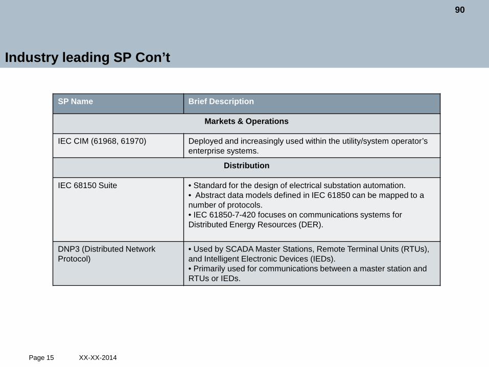
SP Name Brief Description
Markets & Operations
IEC CIM (61968, 61970) Deployed and increasingly used within the utility/system operator’s enterprise systems.
Distribution
IEC 68150 Suite • Standard for the design of electrical substation automation. • Abstract data models defined in IEC 61850 can be mapped to a number of protocols. • IEC 61850-7-420 focuses on communications systems for Distributed Energy Resources (DER).
DNP3 (Distributed Network Protocol)
• Used by SCADA Master Stations, Remote Terminal Units (RTUs), and Intelligent Electronic Devices (IEDs). • Primarily used for communications between a master station and RTUs or IEDs.
Industry leading SP Con’t
90

XX-XX-2014 Page 16
SP Name Brief Description
Distribution Con’t
ICCP–IEC 60870-6 TASE.2 Developed to allow two or more utilities to exchange real-time data, schedule, and control commands.
IEEE 1547 • Standard for Interconnecting Distributed Resources with Electric Power Systems. • Provides a set of criteria and requirements for the interconnection of DG. • Many utilities follow the standard
IEEE P1547 Revision – in development
• Since the re-approval of 1547 in 2008 significant changes in DG space. • Interim amendment released May 2014, allows for limited voltage and frequency ride through and the ability to actively control voltage. • Full revision of the standard started April 2014, aim to release by 2018. • Main revisions are likely to include: • Wider frequency and voltage ride through. • Requirement for interoperability and communications interfaces. • Microgrids. • DG on secondary grid networks.
Industry leading SP Con’t
91

XX-XX-2014 Page 17
SP Name Brief Description
Distribution Con’t
IEEE P2030.2 – in development • Guidelines for energy storage systems integrated with the grid. • Builds upon IEEE Std 2030 Guide • Provides guidance on technical characteristics, integration, compatibly, terminology, functional performance, operation, testing and application of energy storage systems.
Customers & Service Providers
Open ADR • A NIST Smart Grid data model standard. • Developed to facilitate one and 2-way price and demand response interactions between customers and the Smart Grid entities. • Not a prescriptive format, but flexible. • Presents a client-server architecture that is independent of the communication protocol. • Intended to enable automated response from smart buildings and devices be scalable, low-cost, non-propriety, industry supported, with a compliance path for interoperability certification.
Open Charge Point Protocol (OCPP):
• European communication protocol used to communicate charging session information and settlement with EVs and EVSEs. • Developing fast and being adopted around the world
Industry leading SP Con’t
92

XX-XX-2014 Page 18
SP Name Brief Description
Customers & Service Providers Con’t
FSGIM (NEMA & ASHRAE) Create a common information model to enable management of residential commercial and industrial DER to response to communication with a smart electrical grid and electrical service providers.
IEC 61850-7-420 Communications systems for Distributed Energy Resources (DER)
IEEE 2030.5 – Smart Energy Profile 2.0 – in development
• Defines the application protocol to enable utility management of the end user energy environment • Will include demand response, load control, time of day pricing, management of distributed generation, electric vehicles, etc.
SunSpec • Distributed energy industry participants, pursuing information standards to enable “plug & play” system interoperability. • Address operational aspects of PV power plants on the smart grid—including residential, commercial, and utility-scale systems.
NEC • National Electrical Code is a standard that most if not all customers are subject to and are working to harmonize the smart grid with customers SP.
Industry leading SP Con’t
93

XX-XX-2014 Page 19
SP Name Brief Description
Overarching SP
NIST & SGiP Framework • Provides a national and international focus on smart grid. • Lists out all the main SP associated with SG. • Framework 3.0 is currently out for comments
IEEE P2030 • A Guide for Smart Grid Interoperability. • Based on NIST conceptual model. • Provides a methodology for developing a smart grid architecture based on three layers: Power, Communications and IT.
NIST-R 7628 Describes guidelines for cyber-security for the Smart Grid, considers NERC-CIP.
IPV6 • Latest Internet protocol is being discussed in the industry as potentially leading smart grid communications. The protocol is advertized as having the enhanced address space, routing and security that will be required for universal smart grid connectivity.
Industry leading SP Con’t
94

XX-XX-2014 Page 20
The current use of SP in NY
Objective: Highlight the major/most popular SP currently being used in NY that should be considered in the DSPP. Demand-side Resources Integration with the NYISO • NYISO networking, control and security SP apply to the sophisticated integration of DERs.
• Today, more than 100 MW of demand response (curtailment of large loads) is under NYISO automatic generator control (6 second control and telemetry signals) to provide grid reliability (synchronous reserves).
• The SP, commonly used for generators, initially presented a high-cost barrier.
• A combination of NYISO rule changes and technical innovation (NYSERDA project) enabled smaller resources to meet the same SP at a lower cost.
95

XX-XX-2014 Page 21
The current use of SP in NY Con’t
In use today by Con Ed for utility device automation near ‘edge of grid’ • DNP3. • IEC 61850. • IEEE 1547 – Interconnection w/ special methodology Con Ed for n-2 • ISA/IEC-62443 - cyber security management system utility control systems National Grid • Public available technical installation standards and guidelines for distributed generator integration with the utility – ESB 756.
96

XX-XX-2014 Page 22
The current use of SP in NY con’t – DOE CONED DERMS
• Developed secure interoperable platform to monitor & control load and DER.
• Integrate legacy & smart grid data systems with established SP.
• Developed Secured Web Services for internal and external communication with third party providers.
• A blueprint for urban, underground smart grid deployment.
SP Followed NIST 1108 – Smart Grid Frame Work NIST 7628 – Smart Grid cyber security control NIST 800.53 – Web Services (non-MPLS) FIPS 199 - Federal Information Processing
Standard for secure transmission
97

XX-XX-2014 Page 23
DSPP Architecture Benefits
Five key benefits for DSPP architecture development: 1. Architecture identifies gaps in technologies, and SP. 2. Architecture creates interoperability through the definition of domains, boundaries
and terms. 3. A common NY DSPP architecture that all parties can understand and
communicate with when developing something as complex as the DSPP. 4. Architecture can describe the evolution of DSPP functionality over time. 5. A common framework to show DSPP interactions.
98

XX-XX-2014 Page 24
Architecture Standards
24
IET SGAM
Intelli Grid 2.0
NIST & SGiP 2.0
GWAC
BulkGeneration
Customer
Control and Operations
DistributionTransmission
Service ProvidersMarkets
Plant Control
Transmission Field Device
Transmission Substation
Customer Energy
Management and Control
BillingEnergy Market
Clearing
ISO/RTO Wholesale
Trading
ISO/RTO Operation
Distribution Management
Outage Management
Wide-Area Monitoring
Dispatch
Customer Energy Portal
Utility Revenue Metering
Meter Data Management
Distribution Field Device
Distributed Energy
Resources(Local
Generation)
Distribution Operation
Energy Management
Transmission Operation
Geographic Information
Management
Customer Information
Distribution Mobile
Workforce Management
Distribution Asset
Management
Transmission Asset
Management
Transmission Mobile
Workforce Management
Distribution Substation
IT12
IT16
IT7IT8IT9
IT6
IT3
IT2IT1
IT4
IT5
IT20
IT27
IT33
IT35
IT22
IT21IT14 IT15
IT19
IT25
IT30
IT13
IT10
IT34
IT17
IT23
IT26
IT31
IT32
IT29
IT18
IT11
IT28
IT24
Demand Management
P2030
NIST 3.0
99

XX-XX-2014 Page 25 25
NIST 2.0 & SGiP
Major DSPP Interfaces
DER
“A picture speaks a thousand words”
100

XX-XX-2014 Page 26
IEEE 2030 Architecture
Focus on key control and communications areas needed for DSPP NIST Compliant National standard Readily accepted and understood IEEE is open to enhance as it matures Most practical to use with initial WG and timeframe
101

XX-XX-2014 Page 27
Use Case - Dynamic Electricity Production forecasting
• Dynamic electricity production forecasting is the calculation and forecasting of electricity production from Distributed Energy Resources (DER).
• The forecasting is based on based on geography, forecasted fuel supply, solar isolation, wind speed and state of charge.
• The purpose of the forecasts would be to provide supply information to DSPP grid operations and planning, and to help set supply prices in the DSPP market.
•The next few slides paint a story of the DSPP in action with the use of a conceptual architecture.
• Please note this is only an example an is subject to change.
102

XX-XX-2014 Page 28
cat
IT Layer
Distribution Management
Next Day Ahead
Forecast
IT27
Distributed Energy
Resources(Local
Generation)
Command Issued to
identify DER participation
Geographic Information
Management
Request for DER
Geographic Location
IT34
Availability, Geo &
Weather Combined
Energy Market
Clearing
Combined DER Forecast Data Issued
to Operations
Retail Market Clears DER Participation
IT36
Distribution Operation
DER Dispatch Checked for
Security Constraints
IT13
Cleared DER Forecast Issued to
Retail Market
Adapted and reprinted with permission from IEEE. Copyright IEEE 2011. All rights reserved
103

XX-XX-2014 Page 29
Use Case - Dynamic Electricity Production forecasting
Power Layer Adapted and reprinted with permission from IEEE. Copyright IEEE 2011. All rights reserved
104

XX-XX-2014 Page 30
Use Case - Dynamic Electricity Production forecasting
Comms Layer
Adapted and reprinted with permission from IEEE. Copyright IEEE 2011. All rights reserved
105

XX-XX-2014 Page 31
Major Issues & Suggestions in SP for DSPP
Major Issues Suggestions
Interoperability of SP for present and future
• Need harmonization of standards • Interoperability for DSPP has already begun and should be continued • Support testing and certification to ensure interoperability and accelerate their adoption • Encourage, support and incentivize SP interoperability, scalability and future proofing
SP are in various maturity levels & adoption rates
• Utilize existing adoption and industry-supported SP to scale and/or enhance support for additional services within the distribution system • Access SP maturity and adoption levels. • Don’t wait for the most optimal SP
No acceptance of common cyber-security scheme
• Use secure standards-based protocols as basis for the communications models. • Investigate cyber security of open SP, in depth. • Cyber security should be integrated into the DSPP design not an add-on.
DSPP complexity and diversity Need a rigorous architectural approach utilizing use case methodology.
How to maximize customer choice
Encourage SP that not only provides monitoring and control capabilities to the customers but also provides multiple pricing signals.
DSPP costs and market adoption.
• Encourage the use of national and open SP. • Interoperability and harmonization will commoditize equipment and thus increase customer and utility uptake.
106

XX-XX-2014 Page 32
References
http://smartgridstandardsmap.com/ - Online IEC tool to find SP. http://www.nist.gov/smartgrid/upload/NIST_Framework_Release_2-0_corr.pdf - copy of approved NIST standards, http://www.nist.gov/smartgrid/framework3.cfm - out for comments. http://grouper.ieee.org/groups/scc21/ - P2030, 1547 and solar PV group of standards. http://collaborate.nist.gov/twiki-sggrid/bin/view/SmartGrid/SGIPCoSStandardsInformationLibrary - SGiP table of standards. https://www.oasis-open.org/ - OASIS website
107

XX-XX-2014 Page 33
References
http://ec.europa.eu/energy/gas_electricity/smartgrids/doc/xpert_group1_reference_architecture.pdf - SGAM (European Smart Grid Architecture Standards) http://greenbuttondata.org/ - The list of companies currently adopt Green Button: http://openadr.org/ - Companies supporting OpenADR Profile Specifications http://www.nfpa.org/~/media/Files/Research/Research%20Foundation/Research
%20Foundation%20reports/Electrical/rfsmartgridreport.pdf - NFPA harmonization of smart grid and customer standards.
:
108

XX-XX-2014 Page 34
Thank you for your attention!
David Lovelady – Working subgroup leader Power Systems Consultant Siemens PTI
400 State St, Schenectady, NY 12302
Phone: +518 395 5130
E-mail: [email protected]
109

Technologies
110

Page 1 Current Thinking – 06-18-2014
Technologies Subgroup Current Thinking, June 18, 2014
NYS DPS - Platform Technology Working Group
111

Page 2 Current Thinking – 06-18-2014
Members of the Technologies Subgroup
Laney Brown (Iberdrola USA) Deana Dennis (NEMA) Stephanie Bailey (Con Edison) Rob Sheridan (National Grid) Ruben Brown (E Cubed) Maria Seidler (Dominion) Phil Powell (Dominion) Forrest Small (Bridge Energy Group) David O’Brien (Bridge Energy Group) John Johnson (CALM Energy) David Lovelady (Siemens) Jim Gallagher (NY Smart Grid Consortium) Dr. Mani Vadari (NY Smart Grid Consortium) Maria Seidler (Dominion) Marty Uczen (Verizon) David Locke (Verizon) Matt Anglin (NYISO) John Cerveny (NY - Best)
Subgroup Lead - John D'Aloia (Staff)
Henrietta De Veer (Prime Solutions) Laney Brown (Iberdrola USA) Michael Barnett, Steve Snellers (Smart Cloud) Phil Powell (Dominion) Jeremy Tyree (Landis & Gyr) Ward Camp (Landis & Gyr) Michael Vecchi (Landis & Gyr) Anthony Hawkins (Landis & Gyr) Roy Pratt (Bridge Energy Group) Hannah Polikov (Advanced Energy Economy) Aminul Huque (EPRI) Lindsey Rogers (EPRI) Becky Wingenroth (EPRI) Kelly Connell, Chris Graves, Brian Fisher (Staff) Mike Rieder, Peggie Neville, Mike Williams (Staff) Tony Abate, NYSERDA Tom Mimnagh (Con Edison) Brian Horton (Con Edison)
112

Page 3 Current Thinking – 06-18-2014
Subgroup Objectives
• Map enabling technologies to DSPP platform functionalities • Grid, Customer DER/ Microgrids, Market
• Identify technologies that enable DSPP platform functionalities
• Power Systems, Communication Technology, Information Technology layers (IEEE P2030)
• Hardware and software • Cyber-Security
• Identify DSPP technology platform elements
• Maturity • Implementation Phases • Mandatory vs. Optional
• Perform gap analysis • Is the technology necessary for the DSPP platform available?
• YES, can it be used to create platform? • NO, when will it be available? what is the platform road map?
113

Page 4 Current Thinking – 06-18-2014
Procedure/Approach
REV goals
WG Input
Needed Functionalities
Customer/ DER/
Microgrids
Grid
Technologies
Market
Maturity
Power
IT
Comm
Technologies
Technologies
Technologies Power
IT
Comm
Technologies
Technologies
Technologies Power
IT
Comm
Technologies
Technologies
114

Page 5 Current Thinking – 06-18-2014
Functionalities
• Real-time load monitoring • Real-time network monitoring • Adaptive protection • Enhanced fault detection and
location • Outage and restoration
notification • Automated feeder and line
switching (FLISR/FDIR) • Automated voltage and VAR
control • Real-time load transfer • Dynamic capability rating • Diagnosis and notification of
equipment condition • Power flow control • Automated islanding and
reconnection (microgrid) • Electricity storage • Algorithms for grid control and
optimization
• Direct load control • DER power control • DER power factor control • Automated islanding and
reconnection • Electricity storage • Algorithms and analytics
for Customer/DER/Microgrid control and optimization
• Dynamic event notification • Dynamic pricing • Market-based demand
response • Dynamic electricity
production forecasting • Dynamic electricity
consumption forecasting • M&V for producers and
consumers (premise/appliance/resource)
• Participant registration and relationship management
• Confirmation and settlement • Billing, receiving and cash
management • Free-market trading • Algorithms and analytics for
market information and operations
Grid Customer/DER/ Microgrid Market
115

Page 6 Current Thinking – 06-18-2014
Enabling Technologies- IEEE P2030 Layers
Enabling platform technologies were sorted by the 3 layers of the IEEE P2030 Interoperability Standard Power System, Communication Technology, and Information Technology
116

Page 7 Current Thinking – 06-18-2014
Enabling Technologies Matrix Mapping
• Which technologies have a higher maturity level? • Scale 1-5
• Which technologies are foundational to the platform?
• Mandatory vs. Optional • Where does the technology fit in the DSPP phase implementation?
• Phase 1 – first 5 years • Phase 2 – Second 5 years • Phase 3 – ten years and beyond
117

Page 8 Current Thinking – 06-18-2014
Technology Maturity Level
The Hype Cycle is a branded graphical tool developed and used by IT research and advisory firm Gartner for representing the maturity, adoption and social application of specific technologies
Maturity (Gartner hype Cycle) Stage Gartner Description Comments
1 Innovation Trigger Concept/Early R&D 2 Peak of Inflated Expectations Mature R&D
3 Trough of Disillusionment Pilot deployments some successful/some not.
4 Slope of Enlightenment Multiple state deployment
5 Plateau of Productivity Very mature and widely adopted
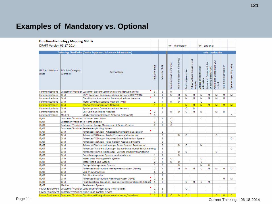
Need Mandatory m Optional o
DSPP Phase of Implementation 1 First 5 years 2 Second 5 years 3 10 years and beyond
Gartner Hype Cycle https://www.gartner.com/login/loginInitAction.do?method=initialize&TARGET=http://www.gartner.com/d
ocument/709015
Matrix Key: Maturity Stage, Platform Need, DSPP Implementation Phase
(Ex. Customer System Communication Network (HAN))
(Ex. SCADA Communication Network)
118

Technology Matrix Mapping Toolgy pp g
FunctionalitiesFunctionalities
Technologies
DSPP Phase
MaturityArchitecture layers
Page 9 Current Thinking – 06-18-2014
119

Page 10 Current Thinking – 06-18-2014
Technology Matrix Map Features
•Version •Maturity & Phase Key •Function – Technology •Function Descriptions •Technology Descriptions
120
Page 11 Current Thinking – 06-18-2014
Examples of Mandatory vs. Optional
121

Page 12 Current Thinking – 06-18-2014
Examples of DSPP Phase Implementation
122

Page 13 Current Thinking – 06-18-2014
Evolution of DSPP Capabilities
• An important REV goal is DSPP platform standardization, however, it is recognized that functionality and technologies will evolve over time.
• Current utility distribution data acquisition and control systems (i.e. SCADA) rely almost exclusively on in-house or privately designed networks.
• Third parties (i.e. aggregators) are increasingly providing services using public network connections.
• DSPP use of public networks will require cyber-security hardening.
Innovation, R&D, Custom Solutions
Premium Products & Services / Early
Adopting Customers
Commoditized Products &
Services / Fast Following
Customers
Standard Products & Services / Mass
Market
• DSPP/Third-parties: Demonstration systems
• Third-parties: Commercial facility HVAC monitoring and control (premium services), high-end residential
• DSPP: Commercial facility HVAC monitoring and control (value-added option)
• Third-parties: Differentiated HVAC monitoring and control (premium services)
• DSPP: Ubiquitous HVAC monitoring and control (low-cost or basic service)
• Third-parties: Differentiated HVAC monitoring and control
Technology Adoption Lifecycle
123

Page 14 Current Thinking – 06-18-2014
Evolution Example: Dynamic Event Notification
Content: Emergency events, targeted DR
Channel: Web/text Granularity: borough
/ town
Content: User-specified (personalization)
Channel: Web, text, DR/DER device
Granularity: 2 kilometer diameter
Content: Personalized, real-time plus longer-range forecasts
Channel: Web, text, device plus device control
Granularity: Tailored to device range
Increasing Technical Capability & Maturity Wave 1
Current event management system
Internet (market communications network)
Wave 2 Improved event
management system Secure backhaul
communications network
Penetration of advanced devices and meter communications
Wave 3 Advanced event
management Distribution
automation communications network w/HAN integration
TechnologyPh
ase
for T
ech
Customer System Communications Network (HAN) 3DSPP Backhaul Communications Network (DSPP WAN) 2 Meter Communications Network (FAN) 2DER Communictions Network 2Market Communications Network (Internet?) 1Customer Web Portal 2Customer Energy Management Device/System 2Event Management System (and analytics) 1Meter Data Management System 2Advanced Distribution Management System (ADMS) 2Controllable/Regulating Inverter (DER) 2Direct Load Control Device 3Smart Thermostat 3
Dynamic Event Notification Definition: Automatic notification by the DSPP to market participants of events including, but not limited to: price changes, incentives, penalties, or special circumstances; events or conditions that may effect market operations; events or conditions that may effect electrical network performance or availability such as equipment failure, weather or other hazards; achieving or exceeding various production or consumption targets or thresholds. Such notification would be intended to provide market participants the ability to respond to important situations or conditions in a timely manner.
124

Page 15 Current Thinking – 06-18-2014
Observations/Recommendations
• Defining and mapping the enabling technologies to the DSPP platform functions provides a common roadmap to assess the variety of evolving technologies
• Identifies the technologies existing today • Creates a structure to identify functionalities and technology capabilities over
time • Identifies gaps in technologies
• Cyber-security must take precedence in platform implementation
• Next Steps
• Subgroup recommends continuing to evolve the Matrix Map into a tool that could be used in implementation plans
125

Page 16 Current Thinking – 06-18-2014
Thank you for your attention!
John D’Aloia NY Dept of Public Service Staff 3 Empire State Plaza Albany, NY 12223 Phone: (518) 486-5210
E-mail: [email protected]
126

Appendices
127

Appendix A
Full List of Working Group
& Subgroup Members
128

PARTICIPANT COMPANYAbate, Tony NYSERDAAcker, William NY - BestAndruski, Joel Department of Public ServiceAnglin, Matt NYISOAusten, Phil National GridBailey, Stephanie M. Con EdisonBaldyea, Todd NYSERDABallard, Jeff Iberdrola USA (NYSEG / RG&E)Barnes, John NYSDECBarnett, Michael Smart Cloud, Inc.Bashualdo, Hugo SiemensBharadwaj, Aditya Open Access Technology International, Inc.Bishop, James Maser Consulting P.A.Bochenek, Scott Iberdrola USA (NYSEG / RG&E)Brown, Laney Iberdrola USA (NYSEG / RG&E)Brown, Ruben ECubed Bruno, Clarke Anbaric TransmissionCamp, Ward Landis & GyrCampbell, Greg NYISOCapers, Audrey Department of Public ServiceCappers, Peter Lawrence Berkeley National Laboratory (LBNL)Carlesco, Adam SEIACarter, Pamela Department of Public ServiceCerbin, Andrea Pace Energy & Climate CenterCerveny, John NY - BestChristian, Rory Environmental Defence FundCinadr, Matt ECubed Collar, Gregg DOS/Utility Intervention Unit/Div of Consumer ProtectionConnell, Kelly Department of Public ServiceCrahen, Evan National FuelCross-Call, Dan Rocky Mountain InstituteD'Aloia, John Department of Public ServiceDavidson, Gary NYISODeBroff, Scott Rhodes & Sinon LLPDelurey, Dan Assn. for Demand Response & Smart GridDennis, Deana National Electric Manufacturers Assn. (NEMA)DeVeer, Henrietta Prime Solutions, Inc. / Energy EngineeringDodson, John Thayer Gate EnergyEaston, Elliot Lockheed MartinEsposito, Allison Department of Public ServiceEvans, Debbie Department of Public ServiceFisher, Brian Department of Public ServiceFitzgerald, Brian Cullen and Dykman LLPFlory, John The Alliance Risk GroupFreni, Charles Central HudsonGallagher, James NYS Smart Grid ConsortiumGhatikar, Girish Lawrence Berkeley National Laboratory (LBNL)
Platform Technology Working Group - Full Member List
129

PARTICIPANT COMPANYGillespie, Susan H. Citizens for Local PowerGraves, Christopher Department of Public ServiceGreen, Manna Jo Hudson River Sloop Clearwater, Inc.Hagell, Suzanne NYSDEC Office of Climate ChangeHanley, Ryan Solar CityHarrison, Becky Gridwise AllianceHawkins, Anthony Landis & GyrHoltermann, Mark Central HudsonHorner, Randolph Silicon Solution LLCHorton, Brian Con EdisonHuque, Aminul Electric Power Research Institute (EPRI)Husta, Bruce ItronInsogna, Martin Department of Public ServiceIsaac, Alexandrea Starion Energy, Inc.Johnson, John CALM Energy, Inc.Jolly, Margaret Con EdisonKallaher, Chris Direct EnergyKiddie, Ross ICF InternationalKiliccote, Sila Lawrence Berkeley National Laboratory (LBNL)Koda, Richard Koda Consulting, Inc.Kowalczyk, Ann Verizon CommunicationsKrall, Timothy Exelon CorporationKranz, Brad NRG Energy, Inc.Kristov, Lorenzo California ISOKushman, Kevin Blue Pillar, Inc.Kwong, Lisa Environmental Protection Bureau, NYS Office of the Attorney GeneralLauckner, Kevin Honeywell Smart Grid SolutionsLindenfelzer, Paul Smart Cloud, Inc.Locke, David Verizon CommunicationsLovelady, David Siemens PTIMagee, Tom Con EdisonMager, Michael Couch White, LLPMaitra, Arindam Electric Power Research Institute (EPRI)Malkin, David GE Energy ManagementMcAuliffe, Gary Silver Spring NetworksMcConnell, Erica Keyes, Fox & Wiedman LLPMimnagh, Tom Con EdisonMorris, Jackson NRDCMullany, Sean Department of Public ServiceMurray, FrankNeville, Peggie Department of Public ServiceNielsen, Matt GE Global ResearchO'Brien, David BRIDGE Energy GroupO'Connor, Mark NYPAPanko, Danielle DOS/Utility Intervention Unit/Div of Consumer ProtectionPearson, Arthur W. Lockheed MartinPhoenix, Phillip NYISOPolikov, Hannah Advanced Energy EconomyPowell, Phil Dominion Voltage Inc.
130

PARTICIPANT COMPANYPratt, Roy BRIDGE Energy GroupPratt, William Utilidata, Inc.Quackenbush, Luke Department of Public ServiceRieder, Michael Department of Public ServiceRigberg, Saul DOS/Utility Intervention Unit/Div of Consumer ProtectionRogers, Lindsey Electric Power Research Institute (EPRI)Ross, Valerie Energy Technology SavingsRothstein, Peter New England Clean Energy CouncilRucinski, Randy National FuelRuotolo, Andrea NYS Smart Grid ConsortiumSalter, Raya NRDCSandoval, Ronny Environmental Defense FundSartini, Monica Rhodes & Sinon LLPSchorr, Angela Direct EnergySeidler, Maria Dominion Voltage Inc.Sharif, Maryam New York Power AuthoritySheridan, Robert National GridShort, Tom Electric Power Research Institute (EPRI)Siskind, Esther Solar OneSmall, Forrest BRIDGE Energy GroupSnellers, Steve Smart Cloud, Inc.Spilky, Rich Integrys EnergyStrauss, Valerie Ass'n for Energy Affordability, Inc.Terry, Kandi Just EnergyThomson, Greg Clean CoalitionTurner, Hal Central HudsonTwigg, GeoRG&E Vermont Energy Investment CorporationTyree, Jeremy Landis & GyrUczen, Marty Verizon CommunicationsUmoff, Rick Solar Energy Industries Assn. (SEIA)Vadari, Dr. Mani NYS Smart Grid ConsortiumVecchi, Mike Landis & GyrVedhathiri, Arun NYPA-Build Smart NYVercheak, Susan Con EdisonWallace, Matthew Department of Public ServiceWarner, Chet Pareto EnergyWarshaw, Drew NRG Energy, Inc.Wentlent, Christopher ConstellationWestman, David Con EdisonWilliams, Michael Department of Public ServiceWilton, John SensusWingenroth, Rebecca Electric Power Research Institute (EPRI)Yakel, Joseph Department of Public ServiceZhu, Penny DOS/Utility Intervention Unit/Div of Consumer Protection
131

Platform Functionalities Subgroup
PARTICIPANT COMPANYBrown, Laney (LEAD) Iberdrola USA (NYSEG / RG&E)Bailey, Stephanie Con EdisonBrown, Ruben E CubedFisher, Brian Department of Public ServiceJohnson, John CALM EnergyO'Brien, David BRIDGE Energy GroupPowell, Phil Dominion Voltage Inc.Rob Sheridan National GridSeidler, Maria Dominion Voltage Inc.Small, Forrest BRIDGE Energy Group
Existing Utility Distribution Systems and Capabilities Subgroup
PARTICIPANT COMPANYHorton, Brian (LEAD) Con EdisonBrown, Laney Iberdrola USA (NYSEG / RG&E)Holtermann, Mark Central HudsonSheridan, Rob National Grid
Standards and Protocols Subgroup
PARTICIPANT COMPANYLovelady, David (LEAD) Siemens PTIAbate, Tony NYSERDACappers, Peter Lawrence Berkeley National Laboratory (LBNL)Dennis, Deana National Electric Manufacturers Assn. (NEMA)Gallagher, Jim NYS Smart Grid ConsortiumGhatikar, Girish Lawrence Berkeley National Laboratory (LBNL)Herbst, Tom Silver SpringsKiliccote, Sila Lawrence Berkeley National Laboratory (LBNL)Locke, David Verizon CommunicationsMaitra, Arindam Electric Power Research Institute (EPRI)Neville, Peggie Department of Public ServiceRieder, Michael Department of Public ServiceUczen, Marty Verizon CommunicationsVadari, Dr. Mani NYS Smart Grid ConsortiumVecchi, Michael Landis & GyrWilliams, Mike Department of Public ServiceWingenroth, Rebecca Electric Power Research Institute (EPRI)
Platform Technology Working Group - Subgroups
132

Technologies Subgroup
PARTICIPANT COMPANYD'Aloia, John (LEAD) Department of Public ServiceAbate, Tony NYSERDAAnglin, Matt NYISOBarnett, Michael Smart Cloud, Inc.Brown, Laney Iberdrola USA (NYSEG / RG&E)Camp, Ward Landis & GyrCerveny, John NY - BestConnell, Kelly Department of Public ServiceDe Veer, Henrietta Prime Solutions, Inc. / Energy EngineeringDennis, Deana National Electric Manufacturers Assn. (NEMA)Fisher, Brian Department of Public ServiceGallagher, Jim NYS Smart Grid ConsortiumGraves, Christopher Department of Public ServiceHawkins, Anthony Landis & GyrHorton, Brian Con EdisonHuque, Aminul Electric Power Research Institute (EPRI)Kushman, Kevin Blue PillarLocke, David Verizon CommunicationsLovelady, David Siemens PTIMimnagh, Tom Con EdisonNeville, Peggie Department of Public ServicePolikov, Hannah Advanced Energy EconomyPowell, Phil DominionPratt, Roy BRIDGE Energy GroupRieder, Michael Department of Public ServiceRogers, Lindsey Electric Power Research Institute (EPRI)Seidler, Maria Dominion Voltage Inc.Snellers, Steve Smart Cloud, Inc.Tyree, Jeremy Landis & GyrUczen, Marty Verizon CommunicationsVadari, Dr. Mani NYS Smart Grid ConsortiumVecchi, Michael Landis & GyrWilliams, Michael Department of Public ServiceWingenroth, Becky Electric Power Research Institute (EPRI)
133

Architecture Team
PARTICIPANT COMPANYAbate, Tony NYSERDABrown, Laney Iberdrola USA (NYSEG / RG&E)Connell, Kelly Department of Public ServiceD'Aloia, John Department of Public ServiceFisher, Brian Department of Public ServiceGallagher, Jim NYS Smart Grid ConsortiumHorton, Brian Con EdisonLovelady, David Siemens PTIMimnagh, Tom Con EdisonNeville, Peggie Department of Public ServiceO'Brien, David BRIDGE Energy GroupPratt, Roy BRIDGE Energy GroupRieder, Michael Department of Public ServiceSmall, Forrest BRIDGE Energy GroupVadari, Dr. Mani NYS Smart Grid ConsortiumVecchi, Michael Landis & Gyr
134

Appendix B
Draft of Functions to Policy Mapping Tool – Preliminary in Nature
The following two pages are only a screenshot of the tool. The tool has been filed electronically as “Appendix B” to this report.
135

Cu
sto
mer
kn
ow
led
ge a
nd
to
ols
to m
anag
e b
ills
Mar
ket
anim
atio
n a
nd
leve
rage
or
rate
pay
er c
on
trib
uti
on
s
Syst
em w
ide
effi
cien
cy
Fuel
an
d r
eso
urc
e d
iver
sity
Syst
em r
elia
bili
ty a
nd
res
ilien
cy
CO
2 r
edu
ctio
n
Mar
ket
Op
erat
ion
s
Gri
d O
per
atio
ns
Inte
grat
ed S
yste
m P
lan
nin
g
Grid
Real-time load monitoring Y Y Y Y Y Y
Real-time network monitoring Y Y Y
Adaptive protection Y Y Y
Enhanced fault detection and location Y Y Y
Outage and restoration notification Y Y
Automated feeder and line switching (FLISR/FDIR) Y Y Y
Automated Voltage and VAR control Y Y Y Y Y
Real-time load transfer Y Y Y Y
Dynamic capability rating Y Y Y
Diagnosis/notification of equipment condition Y Y Y Y
Power flow control Y Y Y
Algorithms and analytics for Grid control and optimization Y Y Y Y Y
Customer/DER/Microgrid
Direct load control Y Y Y
DER power control Y Y Y Y Y Y Y
DER power factor control Y Y Y Y Y Y Y
DER optimization Y Y
Automated islanding and reconnection (microgrid) Y Y Y
Electricity storage Y Y Y Y Y Y Y
Algorithms and analytics for Customer/DER/Microgrid control and optimization Y Y Y Y Y Y
Functionality
REV Policy Objectives Domain
136
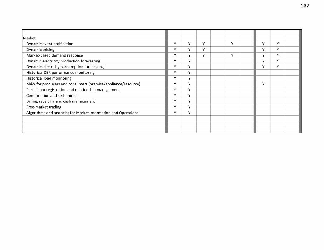
Market
Dynamic event notification Y Y Y Y Y Y
Dynamic pricing Y Y Y Y Y
Market-based demand response Y Y Y Y Y Y
Dynamic electricity production forecasting Y Y Y Y
Dynamic electricity consumption forecasting Y Y Y Y
Historical DER performance monitoring Y Y
Historical load monitoring Y Y
M&V for producers and consumers (premise/appliance/resource) Y Y Y
Participant registration and relationship management Y Y
Confirmation and settlement Y Y
Billing, receiving and cash management Y Y
Free-market trading Y Y
Algorithms and analytics for Market Information and Operations Y Y
137

Appendix C
Draft Use Cases – Preliminary in Nature
The Working Group used the IEEE P2030 standard as a starting point to develop an illustrative framework architecture of the DSPP. The following are a few examples of specific Use Cases out of hundreds of possible Use Cases that the DSPP may need to perform. The Use Cases are preliminary in nature and are for illustrative purposes only.
The Use Cases were adopted from the EPRI Smart Grid Resource Center – Use Case Repository and modified by Working Group Members.
138

Draft Use Cases – Preliminary in Nature
Dynamic Electricity Production Forecasting
139

DDyynnaammiicc EElleeccttrriicciittyy PPrroodduuccttiioonn FFoorreeccaassttiinngg ((DDEEPPFF))
1 Descriptions of Function
1.1 Function Name
Dynamic Electricity Production Forecasting (DEPF)
1.2 Function ID
TBD
1.3 Brief Description
Dynamic electricity production forecasting is the calculation and forecasting of electricity production from Distributed Energy Resources (DER) based on geography, forecasted fuel supply, solar insolation, wind speed, electrical network conditions, or other factors that would affect the quantity and quality of electricity. Production forecasts would change with changes in input data. The purpose of the forecasts would be to provide supply information to DSPP grid operations and planning, and to help set supply prices in the DSPP market.
1.4 Narrative
The primary purpose of dynamic electricity production forecasting is to forecast the varying generation and energy production of Distributed Energy Resources for generation planning in the following time-frames:
• 15-minute • Hour ahead • Day ahead • Weekly.
Input into the dynamic electricity production forecast include historical DER production and weather forecasts of temperature, humidity, wind speed and solar insolation.
III.c.i Dynamic Electricity Production Forecasting 1 Use Case adopted from EPRI Smart Grid Resource Center - Use Case Repository and modified by Working Group Members
140

Results of dynamic electricity production forecasting and generation planning include dynamic generation forecasts and market price signals for price-sensitive distributed energy resources.
1.5 Actor (Stakeholder) Roles [Power System Architecture]
The Power System Architecture includes the following IEEE2030 Standard Domains and Entities:
• Markets • Control and Operations • Service Providers • Customers
Power System information includes:
• DER generation • DER energy production • DER monitoring and control • Market price signals.
Domain Domain Description
Markets The markets domain reflects market operations associated with electric utilities and regional entities. Markets are entities that signal changes in the operation of the system based on market economic variables.
Interface Entity 1 Entity 2 Comments Use Case Example
PS52 Markets Customer Point(s) of Interface
Provides for optimization of distributed generation, storage, and load control (i.e., demand response) on the customer domain. Interfaces include those for control, monitoring, and reporting.
Price Signals
Energy Production
III.c.i Dynamic Electricity Production Forecasting 2 Use Case adopted from EPRI Smart Grid Resource Center - Use Case Repository and modified by Working Group Members
141

Domain Domain Description
Control and Operations The control and operations domain includes three distinctive operation and control entities. These entities control generation, transmission, and distribution.
Interface Entity 1 Entity 2 Comments Use Case Example
PS13 Distribution Operation and Control
Customer Point(s) of Interface
Provides information exchange and control of customer equipment by distribution operations and control. Interfaces include those for control and monitoring.
Generation
Monitoring and Control
PS62 Customer Point(s) of Interface
Customer Distributed Energy Resources
Provides for information exchange and control of DERs by entities external to customer. Interfaces include those for protection, control, and monitoring.
Domain Domain Description
Service Providers The service provider domain contains third parties and utilities that provide electrical power-related services. The service provider domain is the connection between the electric energy markets and the end users.
Interface Entity 1 Entity 2 Comments Use Case Example
PS66 Electric Service Providers
Distribution Operation and Control
Provides for information exchange of expected loading and aggregate control mechanisms. Interfaces include those for monitoring.
Electricity Production Forecasts
Generation
PS68 Electric Service Provider
Customer Point(s) of Interface
Provides for monitoring information and control of customer generation, storage, and loads. Interfaces include those for monitoring and control.
Monitoring and Control
III.c.i Dynamic Electricity Production Forecasting 3 Use Case adopted from EPRI Smart Grid Resource Center - Use Case Repository and modified by Working Group Members
142

Domain Domain Description
Service Providers The service provider domain contains third parties and utilities that provide electrical power-related services. The service provider domain is the connection between the electric energy markets and the end users.
Interface Entity 1 Entity 2 Comments Use Case Example
PS62 Customer Point(s) of Interface
Customer Distributed Energy Resources
Provides for information exchange and control of DERs by entities external to customer. Interfaces include those for protection, control, and monitoring.
Domain Domain Description
Customer The customer domain includes many types of customers that are connected to the electrical distribution system or electrical transmission system.
Interface Entity 1 Entity 2 Comments Use Case Example
PS13 Customer Point(s) of Interface
Distribution Operation and Control
Provides information exchange and control of customer equipment by distribution operations and control. Interfaces include those for control and monitoring.
Generation
Monitoring and Control
PS68 Customer Point(s) of Interface
Electric Service Provider
Provides for monitoring information and control of customer generation, storage, and loads. Interfaces include those for monitoring and control.
Generation
Monitoring and Control
PS52 Customer Point(s) of Interface
Markets Provides for optimization of distributed generation, storage, and load control (i.e., demand response) on the customer domain. Interfaces include those for control, monitoring, and reporting.
Price Signals
Energy Production
III.c.i Dynamic Electricity Production Forecasting 4 Use Case adopted from EPRI Smart Grid Resource Center - Use Case Repository and modified by Working Group Members
143

1.6 Information Exchanged [Communications Architecture]
Information exchanged through the communications architecture includes:
• Control and Operations communications for: o Generation o Monitoring and Control
• Weather Forecasts to include: o Temperature o Humidity o Wind o Solar insolation
• Energy Production: o Energy Production o Historical Production calculation and storage
• Generation Production Forecasts: o 15-minute o Hour ahead o Day ahead o Weekly.
Interface Entity 1 Entity 2 Comments Use Case Example
CT3 Utility Operation and Control/ Enterprise
Neighborhood Area Network
This is a communications network that connects directly to the utility center. It is usually owned by the utility.
Generation
Monitoring and Control
CT52 Neighborhood Area Network
Energy Services Interfaces/ Customer Premises
The ESI is the interface between NAN and HAN. Through ESI, NAN and HAN can communicate to each other even though they might use different communication technology.
III.c.i Dynamic Electricity Production Forecasting 5 Use Case adopted from EPRI Smart Grid Resource Center - Use Case Repository and modified by Working Group Members
144

Interface Entity 1 Entity 2 Comments Use Case Example
Network
CT16 Energy Services Interfaces/ Customer Premises Network
Distributed Energy Resources Network
This provides connectivity between the ESI (which may be a stand-alone device or could be integrated into the smart meter itself) and the DER network via the CPN to the DER in order to support functions such as charging, billing, load shedding, generation, and storage. Here (CT16), we only consider the case where the DER is capable of communication with the ESI.
CT27 Public Internet/ Intranet
Utility Operation and Control/ Enterprise
It connects the utility control/operation/enterprise center to the third-party service provider, ISP, WSP, and other providers through the public Internet.
Weather Forecasts:
• Temperature
• Humidity
• Wind
• Solar insolation
CT23 Public Internet/ Intranet
Third-Party Services
It connects the third-party network (value-added service provider) to the public Internet.
CT25 Utility Operation and Control/ Enterprise
Third-Party Services
It connects the third-party network (value-added service provider) to the utility control/operation/enterprise center. It is usually part of an open ADE data exchange arrangement where the third-party network accesses customer metering/billing and energy consumption information through the utility’s data repositories. Other schemes involve third-party demand response and other services.
Generation
Historical Production
Electricity Production Forecasts
CT24 Markets Third-Party Services
It connects the third-party network (value-added service provider) to the markets for energy/electricity price signaling information.
Price Signals
Energy Production
III.c.i Dynamic Electricity Production Forecasting 6 Use Case adopted from EPRI Smart Grid Resource Center - Use Case Repository and modified by Working Group Members
145

1.7 Activities/Services [Information Technology Architecture]
These services provide systems and applications for Distribution Operations monitoring and control of the Distributed Energy Resources.
Interface Entity 1 Entity 2 Comments Use Case Example
IT13 Distribution Operation
Distribution Management
The information supports real-time monitoring and control of the distribution system.
Monitoring and Control
IT27 Distribution Management
Distributed Energy Resources (Local Generation)
Power system monitoring (capacity, availability, etc.) of distributed (customer) generation. Possible reactive power control.
III.c.i Dynamic Electricity Production Forecasting 7 Use Case adopted from EPRI Smart Grid Resource Center - Use Case Repository and modified by Working Group Members
146

1.8 Contracts/Regulations
N/A
Identify any overall (human-initiated) contracts, regulations, policies, financial considerations, engineering constraints, pollution constraints, and other environmental quality issues that affect the design and requirements of the Function.
Contract/Regulation Impact of Contract/Regulation on Function
Policy
From Actor
May Shall Not
Shall Description (verb) To Actor
ProvideEnergy ESP X Provide power on demand Customer
III.c.i Dynamic Electricity Production Forecasting 8 Use Case adopted from EPRI Smart Grid Resource Center - Use Case Repository and modified by Working Group Members
147

Constraint Type Description Applies to
2 Step by Step Analysis of Function N/A at this level of detail.
Describe steps that implement the function. If there is more than one set of steps that are relevant, make a copy of the following section grouping (Steps to implement function, Preconditions and Assumptions, Steps normal sequence, Post-conditions) and provide each copy with its own sequence name.
2.1 Steps to implement function – Name of Sequence Name of this sequence.
2.1.1 Preconditions and Assumptions Describe conditions that must exist prior to the initiation of the Function, such as prior state of the actors and activities
Identify any assumptions, such as what systems already exist, what contractual relations exist, and what configurations of systems are probably in place
Identify any initial states of information exchanged in the steps in the next section. For example, if a purchase order is exchanged in an activity, its precondition to the activity might be ‘filled in but unapproved’.
III.c.i Dynamic Electricity Production Forecasting 9 Use Case adopted from EPRI Smart Grid Resource Center - Use Case Repository and modified by Working Group Members
148

Actor/System/Information/Contract Preconditions or Assumptions
2.1.2 Steps – Name of Sequence Describe the normal sequence of events, focusing on steps that identify new types of information or new information exchanges or new interface issues to address. Should the sequence require detailed steps that are also used by other functions, consider creating a new “sub” function, then referring to that “subroutine” in this function. Remember that the focus should be less on the algorithms of the applications and more on the interactions and information flows between “entities”, e.g. people, systems, applications, data bases, etc. There should be a direct link between the narrative and these steps.
The numbering of the sequence steps conveys the order and concurrency and iteration of the steps occur. Using a Dewey Decimal scheme, each level of nested procedure call is separated by a dot ‘.’. Within a level, the sequence number comprises an optional letter and an integer number. The letter specifies a concurrent sequence within the next higher level; all letter sequences are concurrent with other letter sequences. The number specifies the sequencing of messages in a given letter sequence. The absence of a letter is treated as a default 'main sequence' in parallel with the lettered sequences.
Sequence 1: 1.1 - Do step 1 1.2A.1 - In parallel to activity 2 B do step 1
1.2A.2 - In parallel to activity 2 B do step 2 1.2B.1 - In parallel to activity 2 A do step 1 1.2B.2 - In parallel to activity 2 A do step 2 1.3 - Do step 3
1.3.1 - nested step 3.1 1.3.2 - nested step 3.2
Sequence 2: 2.1 - Do step 1 2.2 – Do step 2
III.c.i Dynamic Electricity Production Forecasting 10 Use Case adopted from EPRI Smart Grid Resource Center - Use Case Repository and modified by Working Group Members
149

# Event Primary Actor Name of Process/Activity
Description of Process/Activity
Information Producer
Information Receiver
Name of Info Exchanged Additional Notes IECSA
Environment
# Triggering event? Identify the name of the event.1
What other actors are primarily responsible for the Process/Activity? Actors are defined in section1.5.
Label that would appear in a process diagram. Use action verbs when naming activity.
Describe the actions that take place in active and present tense. The step should be a descriptive noun/verb phrase that portrays an outline summary of the step. “If …Then…Else” scenarios can be captured as multiple Actions or as separate steps.
What other actors are primarily responsible for Producing the information? Actors are defined in section1.5.
What other actors are primarily responsible for Receiving the information? Actors are defined in section1.5.
(Note – May leave blank if same as Primary Actor)
Name of the information object. Information objects are defined in section 1.6
Elaborate architectural issues using attached spreadsheet. Use this column to elaborate details that aren’t captured in the spreadsheet.
Reference the applicable IECSA Environment containing this data exchange. Only one environment per step.
2.1.3 Post-conditions and Significant Results Describe conditions that must exist at the conclusion of the Function. Identify significant items similar to that in the preconditions section.
Describe any significant results from the Function
Actor/Activity Post-conditions Description and Results
2.2 Architectural Issues in Interactions Elaborate on all architectural issues in each of the steps outlined in each of the sequences above. Reference the Step by number. Double click on the embedded excel file – record the changes and save the excel file (this updates the embedded attachment).
FUTURE USE
1 Note – A triggering event is not necessary if the completion of the prior step – leads to the transition of the following step.
III.c.i Dynamic Electricity Production Forecasting 11
Use Case adopted from EPRI Smart Grid Resource Center - Use Case Repository and modified by Working Group Members
150

2.3 Diagram
Refer to diagrams n IEEE 2030.
For clarification, draw (by hand, by Power Point, by UML diagram) the interactions, identifying the Steps where possible.
FUTURE USE
3 Auxiliary Issues
3.1 References and contacts
TBD
Documents and individuals or organizations used as background to the function described; other functions referenced by this function, or acting as “sub” functions; or other documentation that clarifies the requirements or activities described. All prior work (intellectual property of the company or individual) or proprietary (non-publicly available) work must be so noted.
FUTURE USE
ID Title or contact Reference or contact information
[1]
[2]
3.2 Action Item List
None at this time.
As the function is developed, identify issues that still need clarification, resolution, or other notice taken of them. This can act as an Action Item list.
III.c.i Dynamic Electricity Production Forecasting 12 Use Case adopted from EPRI Smart Grid Resource Center - Use Case Repository and modified by Working Group Members
151

FUTURE USE
ID Description Status
[1]
[2]
3.3 Revision History
TBD
For reference and tracking purposes, indicate who worked on describing this function, and what aspect they undertook.
FUTURE USE
No Date Author Description
0.
III.c.i Dynamic Electricity Production Forecasting 13 Use Case adopted from EPRI Smart Grid Resource Center - Use Case Repository and modified by Working Group Members
152

Draft Use Cases – Preliminary in Nature
Direct Load Control
153

DDiirreecctt LLooaadd CCoonnttrrooll EEvveenntt 55--66--22001100
VVeerrssiioonn 33..00
1 Descriptions of Function All prior work (intellectual property of the company or individual) or proprietary (non-publicly available) work should be so noted.
1.1 Function Name Direct Load Control Event
1.2 Function ID Identification number of the function
1.3 Brief Description The DR solution shall provide the ability to manage direct load control programs. It accomplishes this by managing the transmission of direct load control actions to HAN devices, shown as PEV, Programmable Communicating Thermostat (PCT), load control switch and smart appliances. This solution will also provide interactions with customers to convey direct load control information via in home display (IHD).
FERC states that further development of key standards around Demand Response will enhance interoperability and communications between system operators, demand response resources (also called curtailment resources), and the systems that support them. The following Use Cases on Demand Response supports DOE’s request to identify use cases and relevant standards, particularly around dispatchable curtailment to address loss or unavailability of other resources or shifting consumption to non-peak times.
Demand Response is a temporary change in electricity consumption by demand control devices in response to market or reliability conditions. Demand control devices control loads capable of measurably and verifiably providing temporary changes in demand. Demand Response may be used to support electricity demand or supply management opportunities for reliability or economic reasons. By managing loads through Demand Response the opportunity exists to:
• Engage the consumer by allowing market participation and consumption/billing choices;
• Introduce new markets for aggregators, micro-grid operators, distributed generation;
Direct Load Control V3.2.doc 1 8/17/2010 Use Case adopted from EPRI Smart Grid Resource Center - Use Case Repository and modified by Working Group Members
154

• Control peak power conditions and limit or remove brownout/blackout instances;
• Flatten consumption curves or peaks and shift consumption times;
• Respond to temporary grid anomalies;
• Maximize use of available power and increase system efficiencies through time-of-use (TOU) and dynamic pricing models.
1.4 Narrative
There are three scenarios described in this use case. Scenario #1 details a Demand Response (DR) event using a meter centric approach. (DR via AMI. No EMS.) Scenario #2 details a DR event using an EMS centric approach with the AMI System. (DR signals travel through the Smart Meter to the EMS and back through the Smart Meter.) Scenario #3 details a DR Event using an EMS centric approach with Internet Gateway. (DR signals travel from the DR Application through the internet, to the internet gateway, to the EMS. The Information travels from the devices to the EMS, to the internet Gateway, through the internet, back to the DR Application.)
Scenario #1 - The Demand Response (DR) solution shall provide the ability to manage direct load control programs. It accomplishes this by managing the transmission of direct load control actions to PEV, load-control switch, HAN device, and smart appliances. This solution will also provide interactions with customers to convey direct load control information using an In Home Display (IHD). The initiation of a DR event is triggered by the DR application (a module) of the AMI system, shown as logically separated. The AMI Head-End module sends the DR command/message through the AMI network to the smart meter where is it is transmitted through the Home Area Network (HAN) to the direct load control devices. These commands and messages can include:
• The DR profile which can include
o Temperature change
o On/off parameters
o Pricing information (CPP, TOU)
o Informational messages
• Curtailment requests (direct load control)
Direct Load Control V3.2.doc 2 8/17/2010 Use Case adopted from EPRI Smart Grid Resource Center - Use Case Repository and modified by Working Group Members
155

Figure 1-1 Context Diagram for DR Signal over AMI Network, Smart Meter Centric
Scenario #2 - The DR solution shall provide the ability to manage direct load control programs. It accomplishes this by managing the transmission of direct load control actions to PEV, load-control switch, HAN device, and smart appliances. This solution will also provide interactions with customers to convey direct load control information using an IHD. The initiation of a DR event is triggered by the DR application (a module) of the AMI system, shown as logically separated. The AMI head end module sends the DR command/message through the AMI network to the smart meter. The smart meter relays the information, needed by the home Energy Management System (EMS) which
Direct Load Control V3.2.doc 3 8/17/2010 Use Case adopted from EPRI Smart Grid Resource Center - Use Case Repository and modified by Working Group Members
156

acts as the home control center for electricity consumption. The EMS provides various facilities for the home owner to track his consumption verify trends and be savvier with his electricity consumption. The EMS transmits through the HAN to the direct load control devices. These commands and messages can include:
• The DR profile which can include
o Temperature change
o On/off parameters
o Start & Duration
o Pricing information (CPP, TOU)
o Informational messages, other SEP1.0 DRLC cluster parameters
• Curtailment requests (direct load control)
Direct Load Control V3.2.doc 4 8/17/2010 Use Case adopted from EPRI Smart Grid Resource Center - Use Case Repository and modified by Working Group Members
157

DRApplicationAMI-Head End
EMSSmart Meter
PCT (HAN Device)Smart AppliancePEV Display (IHD)Load Control
Switch
Operations
Customer
1
9
14 1012 1113
AMI Network
2
3
Figure 1-2 Context Diagram for DR Signal over AMI EMS Centric
Direct Load Control V3.2.doc 5 8/17/2010 Use Case adopted from EPRI Smart Grid Resource Center - Use Case Repository and modified by Working Group Members
158

Scenario #3 - The DR solution shall provide the ability to manage direct load control programs. It accomplishes this by managing the transmission of direct load control actions to PEV, load-control switch, HAN device, and smart appliances. This solution will also provide interactions with customers to convey direct load control information using an In Home Display IHD. The initiation of a DR event is triggered by the DR application (a module) of the AMI system, shown as logically separated. The smart meter relays simple meter data needed by the home Energy Management System (EMS). The DR application, through the internet and internet gateway transmits DR commands to the EMS which acts as the home control center for electricity consumption. The EMS provides various facilities for the home owner to track their consumption verify trends and be savvier with his electricity consumption. The EMS transmits through the HAN to the direct load control devices. These commands and messages can include:
• The DR profile which can include
o Temperature change
o On/off parameters
o Pricing information (CPP, TOU)
o Informational messages
• Curtailment requests (direct load control)
Direct Load Control V3.2.doc 6 8/17/2010 Use Case adopted from EPRI Smart Grid Resource Center - Use Case Repository and modified by Working Group Members
159

Figure 1-3 Context Diagram for DR Signal over Internet Gateway EMS Centric
Direct Load Control V3.2.doc 7 8/17/2010 Use Case adopted from EPRI Smart Grid Resource Center - Use Case Repository and modified by Working Group Members
160

1.5 Actor (Stakeholder) Roles
Grouping (Community) , Group Description
Actor Name Actor Type (person, organization, device, system, or subsystem)
Actor Description
Access Point Sub-System The Access Point is a sub-system within the AMI system that performs high volume data transport capabilities.
The Utility’s NOC/Human
Organization The NOC is the Network Operations center for Telecom activities
AMI Head End System The AMI Head-End is the back office system than controls the Advanced Metering Infrastructure.
AMM Module System Automated Meter Management (predecessor to the DR module of the AMI Head-End)
Customer Person Customer of the Electric Service Provider. Contracts with the ESP to receive quality electrical service. Agrees to participate in Demand Response program. May or may not (at time of system operation) choose to participate
Customer Portal System Interactive Web-site that is accessible via the internet that enables the exchange and display of information for the customer.
Distribution Management
Organization Organization within the utility in charge of the distribution of electricity.
Distribution Operations
Organization Organizational Group within the utility responsible for the operations of the distribution system.
DR Application Sub-System Demand Response Application is a sub-system of the AMI System used to issue demand response commands.
Direct Load Control V3.2.doc 8 8/17/2010 Use Case adopted from EPRI Smart Grid Resource Center - Use Case Repository and modified by Working Group Members
161

Grouping (Community) , Group Description
Actor Name Actor Type (person, organization, Actor Description device, system, or subsystem)
DR Service Provider
Organization
EMS (customer)
Device A logical or physical device typically located at the customer facility that acts as a home electricity control center. The EMS is typically connected to the HAN and sends/receives information from various communications means depending on the customer scenario.
EVSE (Electric Vehicle Supply Equipment)
Device Electric Vehicle Supply Equipment manufacturers are delivering Smart charging stations for electric vehicles. These smart charging stations will typically be located at customers’ premises, or at other private and public parking facilities.
EVSE Radio Device The radio within the EVSE that sends and receives information through the HAN
HAN System Home Area Network (Network of communicating energy consuming devices)
HAN Device Device Device owned by customer, utility or third party that is registered on the Home Area Network (HAN). It communicates in a secure way between other HAN devices.
IHD (In-Home Display)
Device In-Home Display presents basic information to the customer such as consumption data, price information or demand response signals.
IHD Radio Device The radio with the IHD that receives and sends the data to the HAN.
Load Control Device Electric switch that can be remotely commanded to open or close.
Direct Load Control V3.2.doc 9 8/17/2010 Use Case adopted from EPRI Smart Grid Resource Center - Use Case Repository and modified by Working Group Members
162

Grouping (Community) , Group Description
Actor Name Actor Type (person, organization, Actor Description device, system, or subsystem)
Switch (LCS)
Load Control Switch Radio
Device The radio that sends and receives data between the controller and the LCS
Meter Device A smart meter electronically tracks how much electricity is used and when it is used. The smart meter is also equipped to send and receive information from/to the AMI network and also from/to the HAN
Metering Department/Human
Organization The Department within the utility in charge of metering electricity consumption
Metering System
System Also called Advanced Metering Infrastructure it is the collection of devices (such as smart meters), systems (such as MDM) and sub-systems (such as relays or Access points) that enable the automated metering solution
NIC Device Network Interface Card within the meter that has 3 elements (NIC - ESI, NIC - ESP & Metrology board)
NIC - ESI Device HAN side of the Network Interface Card within the meter. (Energy Services Interface). Device and software that permits applications such as load control device or in-home display to receive information in a secure fashion.
NIC - ESP Device AMI side of the network interface card within the smart meter.
PCT (Programmable
Device Device on the Home Area Network that is programmable and controllable.
Direct Load Control V3.2.doc 10 8/17/2010 Use Case adopted from EPRI Smart Grid Resource Center - Use Case Repository and modified by Working Group Members
163

Grouping (Community) , Group Description
Actor Name Actor Type (person, organization, Actor Description device, system, or subsystem)
Communicating Thermostat)
PCT Radio Device The radio that sends and receives data between the HAN and the PCT
PEV Device Plug-In Electric Vehicle
PEV Radio Device The radio with the PEV that sends and receives information through the HAN
Relay (AMI) Device A sub-system of the AMI system that typically relays the data using radio signals between the meters and the access points.
Smart Appliance
Device Smart Appliances can react to remote management, whether to price, grid integrity, or other energy management signaling.
Smart Appliance Radio
Device The radio that sends and receives data between the smart appliance and the HAN
Smart Meter Device A digital meter used in measuring watts, vars, var-hours, volt-amperes, or volt-ampere-hours. The Smart Meter is a 2-way communicating device that includes a NIC and is part of an advanced metering infrastructure (AMI). It is located on the customer premise and owned by the distributor or retail provider.
Direct Load Control V3.2.doc 11 8/17/2010 Use Case adopted from EPRI Smart Grid Resource Center - Use Case Repository and modified by Working Group Members
164

1.6 Information Exchanged
Information Object Name Information Object Description
Inadequate generation resources
Direct Load Control Event
(1) Data elements to trigger for Direct Load Control
(2) Data elements to trigger for Direct Load Control Event
(3) Data elements concerning DR Event for In-Home Display
Communications Acknowledgement
Information for DR Event
(4) Data elements to trigger for Direct Load Control Event
Communications Acknowledgement
(5) Data elements to trigger for Direct Load Control Event
Communications Acknowledgement
(6) Data elements to trigger for Direct Load Control Event
Communications Acknowledgement
(7) Data elements to trigger for Direct Load Control Event
Direct Load Control V3.2.doc 12 8/17/2010 Use Case adopted from EPRI Smart Grid Resource Center - Use Case Repository and modified by Working Group Members
165

Information Object Name Information Object Description
Communications Acknowledgement
System Updates
1.7 Activities/Services Describe or list the activities and services involved in this Function (in the context of this Function).
Activity/Service Name Activities/Services Provided
1.8 Contracts/Regulations Identify any overall (human-initiated) contracts, regulations, policies, financial considerations, engineering constraints, pollution constraints, and other environmental quality issues that affect the design and requirements of the Function.
Contract/Regulation Impact of Contract/Regulation on Function
Opt Out Clause Customer may not exceed 5 hours a day
Policy
From Actor
May Shall Not
Shall Description (verb) To Actor
Direct Load Control V3.2.doc 13 8/17/2010 Use Case adopted from EPRI Smart Grid Resource Center - Use Case Repository and modified by Working Group Members
166

Constraint Type Description Applies to
2 Step by Step Analysis of Function Describe steps that implement the function. If there is more than one set of steps that are relevant, make a copy of the following section grouping (Steps to implement function, Preconditions and Assumptions, Steps normal sequence, Post-conditions) and provide each copy with its own sequence name.
2.1 Steps to implement function – Name of Sequence Scenario #1 DR via AMI. No EMS.
2.1.1 Preconditions and Assumptions Describe conditions that must exist prior to the initiation of the Function, such as prior state of the actors and activities.
Actor/System/Information/Contract Preconditions or Assumptions
NIC - ESP It is understood that the ESP is part of the Network Interface Card (NIC) inside the Smart Meter.
NIC - ESI It is understood that the ESI is part of the Network Interface Card (NIC) inside the Smart Meter.
2.1.2 Steps – Name of Sequence
Direct Load Control V3.2.doc 14 8/17/2010 Use Case adopted from EPRI Smart Grid Resource Center - Use Case Repository and modified by Working Group Members
167

# Event Primary Actor Name of Process/Activity
Description of Process/Activity
Information Producer
Information Receiver
Name of Info Exchanged Additional Notes IECSA
Environment
# Triggering event? Identify the name of the event.1
What other actors are primarily responsible for the Process/Activity? Actors are defined in section0.
Label that would appear in a process diagram. Use action verbs when naming activity.
Describe the actions that take place in active and present tense. The step should be a descriptive noun/verb phrase that portrays an outline summary of the step. “If …Then…Else” scenarios can be captured as multiple Actions or as separate steps.
What other actors are primarily responsible for Producing the information? Actors are defined in section0.
What other actors are primarily responsible for Receiving the information? Actors are defined in section0.
(Note – May leave blank if same as Primary Actor)
Name of the information object. Information objects are defined in section 1.6
Elaborate architectural issues using attached spreadsheet. Use this column to elaborate details that aren’t captured in the spreadsheet.
Reference the applicable IECSA Environment containing this data exchange. Only one environment per step.
1.1 Energy Service Provider (ESP) determines that the available generation is inadequate to fulfill the system loads
ESP ESP contacts Distribution Operations
ESP contacts Distribution Operations to report inadequate generation resources
ESP Distribution Operations
Inadequate generation resources
1.2 Distribution Operations
Direct Load Control Event Called
Distribution Operations calls a Direct Load Control Event using the Demand Response Application (demand response event).
Distribution Operations
Demand Response Application
Direct Load Control Event
1 Note – A triggering event is not necessary if the completion of the prior step – leads to the transition of the following step.
Direct Load Control V3.2.doc 15 8/17/2010 Use Case adopted from EPRI Smart Grid Resource Center - Use Case Repository and modified by Working Group Members
168

Name of Description of Information Information Name of Info IECSA # Event Primary Actor Additional Notes Process/Activity Process/Activity Producer Receiver Exchanged Environment
1.3 Demand Response Application
Demand Response Application creates appropriate transactions
Demand Response Application creates appropriate transactions (to send to Customers and Customer’s Devices) to send to the AMI Head End
Demand Response Application
AMI Head End
(1) Data elements to trigger for Direct Load Control
The AMI is ultimately passing data thru the meter to the HAN to the Controllable Devices
IEC 61968
1.4 AMI Head End
AMI Head End send data elements
AMI Head End sends Data elements to trigger for Direct Load Control Event to the NIC - ESP via the AMI Network
AMI Head End
NIC - ESP (2) Data elements to trigger for Direct Load Control Event
Use AMI Network Use Case scenario AMI Head End to Smart Meter
1.5 NIC - ESP NIC - ESP send Data elements
NIC - ESP send Data elements to trigger for Direct Load Control Event to the NIC - ESI
NIC - ESP NIC - ESI (2) Data elements to trigger for Direct Load Control Event
1.6A.1
NIC - ESI NIC - ESI sends Data elements
NIC - ESI sends Data elements concerning DR Event for IHD to IHD Radio
NIC - ESI IHD Radio (3) Data elements concerning DR Event for IHD
1.6A.1.1
IHD Radio IHD Radio receives the signal
IHD Radio receives the signal and sends a Communications Acknowledgement to the NIC - ESI
IHD Radio NIC - ESI Communications Acknowledgement
Direct Load Control V3.2.doc 16 8/17/2010 Use Case adopted from EPRI Smart Grid Resource Center - Use Case Repository and modified by Working Group Members
169

Name of Description of Information Information Name of Info IECSA # Event Primary Actor Additional Notes Process/Activity Process/Activity Producer Receiver Exchanged Environment
1.6.A.2
IHD Radio IHD Radio sends Data elements
IHD Radio sends Data elements concerning DR Event for IHD to IHD
IHD Radio IHD (In-Home Display)
(3) Data elements concerning DR Event for IHD
1.6A.3
IHD (In-Home Display)
IHD displays information
IHD displays information for DR Event
IHD (In-Home Display)
IHD (In-Home Display)
Information for DR Event
1.6B.1
NIC - ESI NIC - ESI sends Data elements
NIC - ESI sends Data elements to trigger for Direct Load Control Event to PCT Radio
NIC - ESI PCT Radio (4) Data elements to trigger for Direct Load Control Event
1.6B.1.1
PCT Radio PCT Radio receives the signal
PCT Radio receives the signal and sends a Communications Acknowledgement to the NIC - ESI
PCT Radio NIC - ESI Communications Acknowledgement
1.6B.2
PCT Radio PCT Radio sends data elements
PCT Radio sends Data elements to trigger for Direct Load Control Event to the PCT Controller
PCT Radio PCT Controller
(4) Data elements to trigger for Direct Load Control Event
Cycling vs. temperature control - ???
1.6B.3
PCT (Programmable Communicating Thermostat)
PCT (Programmable Communicating Thermostat) functions
PCT (Programmable Communicating Thermostat) functions accordingly
PCT (Programmable Communicating Thermostat)
PCT (Programmable Communicating Thermostat)
(4) Data elements to trigger for Direct Load Control Event
Direct Load Control V3.2.doc 17 8/17/2010 Use Case adopted from EPRI Smart Grid Resource Center - Use Case Repository and modified by Working Group Members
170

Name of Description of Information Information Name of Info IECSA # Event Primary Actor Additional Notes Process/Activity Process/Activity Producer Receiver Exchanged Environment
1.6C.1
NIC - ESI NIC - ESI sends Data elements
NIC - ESI sends Data elements to trigger for Direct Load Control Event to Smart Appliances Radio
NIC - ESI Smart Appliances Radio
(5) Data elements to trigger for Direct Load Control Event
1.6C.1.1
Smart Appliances Radio
Smart Appliances Radio receives the signal
Smart Appliances Radio receives the signal and sends a Communications Acknowledgement to the NIC - ESI
Smart Appliances Radio
NIC - ESI Communications Acknowledgement
1.6C.2
Smart Appliances Radio
Smart Appliances Radio sends data elements
Smart Appliances Radio sends Data elements to trigger for Direct Load Control Event to Smart Appliance Device Controller
Smart Appliances Radio
Smart Appliance Device Controller
(5) Data elements to trigger for Direct Load Control Event
1.6C.3
Smart Appliance
Smart Appliance responds
Smart Appliance responds accordingly
Smart Appliance Device Controller
Smart Appliance Device Controller
(5) Data elements to trigger for Direct Load Control Event
1.6D.1
NIC - ESI NIC - ESI sends Data elements
NIC - ESI sends Data elements to trigger for Direct Load Control Event to the Load Control Switch Radio
NIC - ESI Load Control Switch Radio
(6) Data elements to trigger for Direct Load Control Event
Direct Load Control V3.2.doc 18 8/17/2010 Use Case adopted from EPRI Smart Grid Resource Center - Use Case Repository and modified by Working Group Members
171

Name of Description of Information Information Name of Info IECSA # Event Primary Actor Additional Notes Process/Activity Process/Activity Producer Receiver Exchanged Environment
1.6D.1.1
Load Control Switch Radio
Load Control Switch Radio receives the signal
Load Control Switch Radio receives the signal and sends a communications acknowledgement to the NIC - ESI
Load Control Switch Radio
NIC - ESI Communications Acknowledgement
1.6D.2
Load Control Switch Radio
Load Control Switch Radio sends data elements
Load Control Switch Radio sends Data elements to trigger for Direct Load Control Event to Load Control Switch Device Controller
Load Control Switch Radio
Load Control Switch Device Controller
(6) Data elements to trigger for Direct Load Control Event
1.6D.3
Load Control Switch Device Radio
Load Control Switch Device Radio responds
Load Control Switch Device Radio responds accordingly
Load Control Switch Device Radio
Load Control Switch Device Radio
(6) Data elements to trigger for Direct Load Control Event
1.6E.1
NIC - ESI NIC - ESI sends data elements
NIC - ESI sends Data elements to trigger for Direct Load Control Event to EVSE Radio
NIC - ESI EVSE Radio (7) Data elements to trigger for Direct Load Control Event
1.6E.1.1
EVSE Radio EVSE Radio receives the signal
EVSE Radio receives the signal and sends a Communications Acknowledgement to the NIC - ESI
EVSE Radio NIC - ESI Communications Acknowledgement
Direct Load Control V3.2.doc 19 8/17/2010 Use Case adopted from EPRI Smart Grid Resource Center - Use Case Repository and modified by Working Group Members
172

Name of Description of Information Information Name of Info IECSA # Event Primary Actor Additional Notes Process/Activity Process/Activity Producer Receiver Exchanged Environment
1.6E.2
EVSE Radio EVSE Radio sends data elements
EVSE Radio sends Data elements to trigger for Direct Load Control Event to EVSE
EVSE Radio EVSE (7) Data elements to trigger for Direct Load Control Event
1.6E.3
EVSE EVSE responds
EVSE responds accordingly
EVSE EVSE (7) Data elements to trigger for Direct Load Control Event
1.7 NIC - ESI NIC - ESI collects and delivers Communications Acknowledges
NIC - ESI collects and delivers Communications Acknowledges to NIC - ESP
NIC - ESI NIC - ESP Communications Acknowledgements
1.8 NIC - ESI NIC - ESP delivers Communications Acknowledgements
NIC - ESP delivers Communications Acknowledgements to the AMI Head End via the AMI Network
Smart ESP AMI Head End
Communications Acknowledgements
Use AMI Network Use Case Scenario NIC - ESP to AMI Head End
1.9 AMI Head End
AMI Head End delivers Communications Acknowledgements
AMI Head End delivers Communications Acknowledgements to the DR Application
AMI Head End
DR Application
Communications Acknowledgements
Direct Load Control V3.2.doc 20 8/17/2010 Use Case adopted from EPRI Smart Grid Resource Center - Use Case Repository and modified by Working Group Members
173
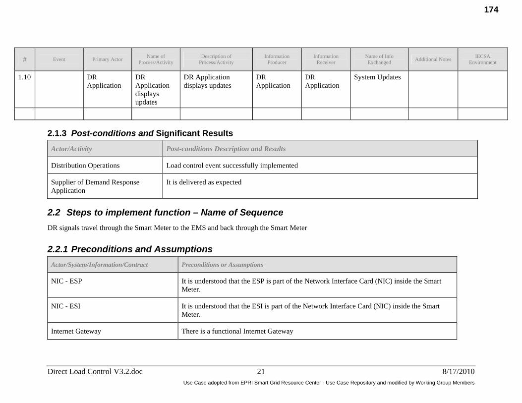
Name of Description of Information Information Name of Info IECSA # Event Primary Actor Additional Notes Process/Activity Process/Activity Producer Receiver Exchanged Environment
1.10 DR Application
DR Application displays updates
DR Application displays updates
DR Application
DR Application
System Updates
2.1.3 Post-conditions and Significant Results
Actor/Activity Post-conditions Description and Results
Distribution Operations Load control event successfully implemented
Supplier of Demand Response Application
It is delivered as expected
2.2 Steps to implement function – Name of Sequence DR signals travel through the Smart Meter to the EMS and back through the Smart Meter
2.2.1 Preconditions and Assumptions Actor/System/Information/Contract Preconditions or Assumptions
NIC - ESP It is understood that the ESP is part of the Network Interface Card (NIC) inside the Smart Meter.
NIC - ESI It is understood that the ESI is part of the Network Interface Card (NIC) inside the Smart Meter.
Internet Gateway There is a functional Internet Gateway
Direct Load Control V3.2.doc 21 8/17/2010 Use Case adopted from EPRI Smart Grid Resource Center - Use Case Repository and modified by Working Group Members
174
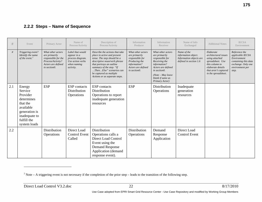
2.2.2 Steps – Name of Sequence
# Event Primary Actor Name of Process/Activity
Description of Process/Activity
Information Producer
Information Receiver
Name of Info Exchanged Additional Notes IECSA
Environment
# Triggering event? Identify the name of the event.2
What other actors are primarily responsible for the Process/Activity? Actors are defined in section0.
Label that would appear in a process diagram. Use action verbs when naming activity.
Describe the actions that take place in active and present tense. The step should be a descriptive noun/verb phrase that portrays an outline summary of the step. “If …Then…Else” scenarios can be captured as multiple Actions or as separate steps.
What other actors are primarily responsible for Producing the information? Actors are defined in section0.
What other actors are primarily responsible for Receiving the information? Actors are defined in section0.
(Note – May leave blank if same as Primary Actor)
Name of the information object. Information objects are defined in section 1.6
Elaborate architectural issues using attached spreadsheet. Use this column to elaborate details that aren’t captured in the spreadsheet.
Reference the applicable IECSA Environment containing this data exchange. Only one environment per step.
2.1 Energy Service Provider determines that the available generation is inadequate to fulfill the system loads
ESP ESP contacts Distribution Operations
ESP contacts Distribution Operations to report inadequate generation resources
ESP Distribution Operations
Inadequate generation resources
2.2 Distribution Operations
Direct Load Control Event Called
Distribution Operations calls a Direct Load Control Event using the Demand Response Application (demand response event).
Distribution Operations
Demand Response Application
Direct Load Control Event
2 Note – A triggering event is not necessary if the completion of the prior step – leads to the transition of the following step.
Direct Load Control V3.2.doc 22 8/17/2010 Use Case adopted from EPRI Smart Grid Resource Center - Use Case Repository and modified by Working Group Members
175

Name of Description of Information Information Name of Info IECSA # Event Primary Actor Additional Notes Process/Activity Process/Activity Producer Receiver Exchanged Environment
2.3 Demand Response Application
Demand Response Application creates appropriate transactions (to send to Customers and Customer’s Devices) to send to the AMI Head End
Demand Response Application
AMI Head End
(1) Data elements to trigger for Direct Load Control
The AMI is ultimately passing data thru the meter to the HAN to the Controllable Devices
IEC 61968
2.4 AMI Head End
AMI Head End sends transactions
AMI Head End sends Data elements to trigger for Direct Load Control Event to the NIC - ESP via the AMI Network
AMI Head End
NIC - ESP (2) Data elements to trigger for Direct Load Control Event
Use AMI Network Use Case scenario AMI Head End to Smart Meter
2.5 NIC - ESP NIC - ESP send Data elements
NIC - ESP send Data elements to trigger for Direct Load Control Events to the NIC - ESI
NIC - ESP NIC - ESI (2) Data elements to trigger for Direct Load Control Event
2.6 NIC - ESP NIC - ESP send Data elements
NIC - ESI send Data elements to trigger for Direct Load Control Events to the EMS
NIC - ESI EMS (2) Data elements to trigger for Direct Load Control Event
2.7A.1
EMS EMS sends Data elements
EMS sends Data elements concerning DR Event for IHD to IHD Radio
EMS IHD Radio (3) Data elements concerning DR Event for IHD
Direct Load Control V3.2.doc 23 8/17/2010 Use Case adopted from EPRI Smart Grid Resource Center - Use Case Repository and modified by Working Group Members
176

Name of Description of Information Information Name of Info IECSA # Event Primary Actor Additional Notes Process/Activity Process/Activity Producer Receiver Exchanged Environment
2.7A.1.1
IHD Radio IHD Radio receives the signal
IHD Radio receives the signal and sends a Communications Acknowledgement to the EMS
IHD Radio EMS Communications Acknowledgement
2.7.A.2
IHD Radio IHD Radio sends data elements
IHD Radio sends Data elements concerning DR Event for IHD to IHD
IHD Radio IHD (In-Home Display)
(3) Data elements concerning DR Event for IHD
2.7A.3
IHD (In-Home Display)
IHD (In-Home Display) displays information
IHD (In-Home Display) displays information for DR Event
IHD (In-Home Display)
IHD (In-Home Display)
Information for DR Event
2.7B.1
EMS (customer)
EMS (customer)sends data elements
EMS (customer)sends Data elements to trigger for Direct Load Control Event to PCT Radio
EMS (customer)
PCT Radio (4) Data elements to trigger for Direct Load Control Event
2.7B.1.1
PCT Radio PCT Radio receives the signal
PCT Radio receives the signal and sends a Communications Acknowledgement to the EMS (customer)
PCT Radio EMS Communications Acknowledgement
Direct Load Control V3.2.doc 24 8/17/2010 Use Case adopted from EPRI Smart Grid Resource Center - Use Case Repository and modified by Working Group Members
177

Name of Description of Information Information Name of Info IECSA # Event Primary Actor Additional Notes Process/Activity Process/Activity Producer Receiver Exchanged Environment
2.7B.2
PCT Radio PCT Radio sends data elements
PCT Radio sends Data elements to trigger for Direct Load Control Event to the PCT (Programmable Communicating Thermostat)
PCT Radio PCT (Programmable Communicating Thermostat)
(4) Data elements to trigger for Direct Load Control Event
Cycling vs. temperature control - ???
2.7B.3
PCT (Programmable Communicating Thermostat)
PCT (Programmable Communicating Thermostat)functions
PCT (Programmable Communicating Thermostat)functions accordingly
PCT (Programmable Communicating Thermostat)
PCT (Programmable Communicating Thermostat)
(4) Data elements to trigger for Direct Load Control Event
2.7C.1
EMS EMS sends data elements
EMS sends Data elements to trigger for Direct Load Control Event to Smart Appliances Radio
EMS Smart Appliances Radio
(5) Data elements to trigger for Direct Load Control Event
2.7C.1.1
Smart Appliances Radio
Smart Appliances Radio receives the signal
Smart Appliances Radio receives the signal and sends a Communications Acknowledgement to the EMS
Smart Appliances Radio
EMS Communications Acknowledgement
Direct Load Control V3.2.doc 25 8/17/2010 Use Case adopted from EPRI Smart Grid Resource Center - Use Case Repository and modified by Working Group Members
178

Name of Description of Information Information Name of Info IECSA # Event Primary Actor Additional Notes Process/Activity Process/Activity Producer Receiver Exchanged Environment
2.7C.2
Smart Appliances Radio
Smart Appliances Radio sends data elements
Smart Appliances Radio sends Data elements to trigger for Direct Load Control Event to Smart Appliance
Smart Appliances Radio
Smart Appliance
(5) Data elements to trigger for Direct Load Control Event
2.7C.3
Smart Appliance Device
Smart Appliance responds
Smart Appliance responds accordingly
Smart Appliance
Smart Appliance
(5) Data elements to trigger for Direct Load Control Event
2.7D.1
EMS (customer)
EMS (customer)sends data elements
EMS (customer)sends Data elements to trigger for Direct Load Control Event to the Load Control Switch Radio
EMS (customer)
Load Control Switch Radio
(6) Data elements to trigger for Direct Load Control Event
2.7D.1.1
Load Control Switch Radio
Load Control Switch Radio receives the signal
Load Control Switch Radio receives the signal and sends a Communications Acknowledgement to the EMS
Load Control Switch Radio
EMS (customer)
Communications Acknowledgement
2.7D.2
Load Control Switch Radio
Load Control Switch Radio sends data elements
Load Control Switch Radio sends Data elements to trigger for Direct Load Control Event to Load Control Switch Device Controller
Load Control Switch Radio
Load Control Switch Device Controller
(6) Data elements to trigger for Direct Load Control Event
Direct Load Control V3.2.doc 26 8/17/2010 Use Case adopted from EPRI Smart Grid Resource Center - Use Case Repository and modified by Working Group Members
179

Name of Description of Information Information Name of Info IECSA # Event Primary Actor Additional Notes Process/Activity Process/Activity Producer Receiver Exchanged Environment
2.7D.3
Load Control Switch
Load Control Switch responds
Load Control Switch responds accordingly
Load Control Switch
Load Control Switch
(6) Data elements to trigger for Direct Load Control Event
2.7E.1
EMS (customer)
EMS (customer) sends data elements
EMS (customer) sends Data elements to trigger for Direct Load Control Event to EVSE Radio
EMS (customer)
EVSE Radio (7) Data elements to trigger for Direct Load Control Event
2.7E.1.1
EVSE Radio EVSE Radio receives the signal
EVSE Radio receives the signal and sends a Communications Acknowledgement to the EMS
EVSE Radio EMS (customer)
Communications Acknowledgement
2.7E.2
EVSE Radio EVSE Radio sends data elements
EVSE Radio sends Data elements to trigger for Direct Load Control Event to EVSE
PEV EVSE (7) Data elements to trigger for Direct Load Control Event
2.7E.3
EVSE EVSE responds
EVSE responds accordingly
EVSE EVSE (7) Data elements to trigger for Direct Load Control Event
Direct Load Control V3.2.doc 27 8/17/2010 Use Case adopted from EPRI Smart Grid Resource Center - Use Case Repository and modified by Working Group Members
180

Name of Description of Information Information Name of Info IECSA # Event Primary Actor Additional Notes Process/Activity Process/Activity Producer Receiver Exchanged Environment
2.8 EMS (customer)
EMS (customer)delivers Communications Acknowledgements
EMS (customer)delivers Communications Acknowledgements to NIC - ESI
EMS (customer)
NIC - ESI Communications Acknowledgements
2.9 NIC - ESI NIC - ESI collects and delivers Communications Acknowledgements
NIC - ESI collects and delivers Communications Acknowledgements to NIC - ESP
NIC - ESI NIC - ESP Communications Acknowledgements
2.10 NIC - ESP NIC - ESP delivers Communications Acknowledgements
NIC - ESP delivers Communications Acknowledgements to the AMI Head End via the AMI Network
NIC - ESP AMI Head End
Communications Acknowledgements
Use AMI Network Use Case Scenario NIC - ESP to AMI Head End
2.11 AMI Head End
AMI Head End delivers Communications Acknowledgements
AMI Head End delivers Communications Acknowledgements to the DR Application
AMI Head End
DR Application
Communications Acknowledgements
2.12 DR Application
DR Application displays updates
DR Application displays updates
DR Application
DR Application
System Updates
Direct Load Control V3.2.doc 28 8/17/2010 Use Case adopted from EPRI Smart Grid Resource Center - Use Case Repository and modified by Working Group Members
181

2.2.3 Post-conditions and Significant Results
Actor/Activity Post-conditions Description and Results
Distribution Operations Load control event successfully implemented
Supplier of Demand Response Application
It is delivered as expected
2.3 Steps to implement function – Name of Sequence DR signals travel from the DR Application through the internet, to the internet gateway, to the EMS. The Information travels from the devices to the EMS, to the internet Gateway, through the internet, back to the DR Application
2.3.1 Preconditions and Assumptions Actor/System/Information/Contract Preconditions or Assumptions
NIC - ESP It is understood that the ESP is part of the Network Interface Card (NIC) inside the Smart Meter.
NIC - ESI It is understood that the ESI is part of the Network Interface Card (NIC) inside the Smart Meter.
Internet Gateway There is a functional Internet Gateway
2.3.2 Steps – Name of Sequence
Direct Load Control V3.2.doc 29 8/17/2010 Use Case adopted from EPRI Smart Grid Resource Center - Use Case Repository and modified by Working Group Members
182

# Event Primary Actor Name of Process/Activity
Description of Process/Activity
Information Producer
Information Receiver
Name of Info Exchanged Additional Notes IECSA
Environment
# Triggering event? Identify the name of the event.3
What other actors are primarily responsible for the Process/Activity? Actors are defined in section0.
Label that would appear in a process diagram. Use action verbs when naming activity.
Describe the actions that take place in active and present tense. The step should be a descriptive noun/verb phrase that portrays an outline summary of the step. “If …Then…Else” scenarios can be captured as multiple Actions or as separate steps.
What other actors are primarily responsible for Producing the information? Actors are defined in section0.
What other actors are primarily responsible for Receiving the information? Actors are defined in section0.
(Note – May leave blank if same as Primary Actor)
Name of the information object. Information objects are defined in section 1.6
Elaborate architectural issues using attached spreadsheet. Use this column to elaborate details that aren’t captured in the spreadsheet.
Reference the applicable IECSA Environment containing this data exchange. Only one environment per step.
3.1 Energy Service Provider determines that the available generation is inadequate to fulfill the system loads
ESP ESP contacts Distribution Operations
ESP contacts Distribution Operations to report inadequate generation resources
ESP Distribution Operations
Inadequate generation resources
3.2 Distribution Operations
Direct Load Control Event Called
Distribution Operations calls a direct load control or demand response event using the Demand Response Application.
Distribution Operations
Demand Response Application
Direct Load Control Event
3 Note – A triggering event is not necessary if the completion of the prior step – leads to the transition of the following step.
Direct Load Control V3.2.doc 30 8/17/2010 Use Case adopted from EPRI Smart Grid Resource Center - Use Case Repository and modified by Working Group Members
183

# Event Primary Actor Name of Process/Activity
Description of Process/Activity
Information Producer
Information Receiver
Name of Info Exchanged Additional Notes IECSA
Environment
3.3 Demand Response Application
Demand Response Application creates appropriate transactions
Demand Response Application creates appropriate transactions (to send to Customers and Customer’s Devices) to send to the Internet Gateway via the internet
Demand Response Application
Internet Gateway
(1) Data elements to trigger for Direct Load Control
The AMI is ultimately passing data thru the meter to the HAN to the Controllable Devices
IEC 61968
3.4 Internet Gateway
Internet Gateway sends transactions
Internet Gateway sends transactions to the EMS (customer)
Internet Gateway
EMS (customer)
(2) Data elements to trigger for Direct Load Control Event
3.5A.1
EMS (customer)
EMS (customer)sends data elements
EMS (customer)sends Data elements concerning DR Event for IHD to IHD Radio
EMS (customer)
IHD Radio (3) Data elements concerning DR Event for IHD
3.5A.1.1
IHD Radio IHD Radio receives the signal and sends a Communications Acknowledgement
IHD Radio receives the signal and sends a Communications Acknowledgement to the EMS
IHD Radio EMS Communications Acknowledgement
3.5A.2
IHD (In-Home Display)
IHD Radio sends data elements
IHD Radio sends Data elements concerning DR Event for IHD to IHD
IHD Radio IHD (In-Home Display)
(3) Data elements concerning DR Event for IHD
Direct Load Control V3.2.doc 31 8/17/2010 Use Case adopted from EPRI Smart Grid Resource Center - Use Case Repository and modified by Working Group Members
184

# Event Primary Actor Name of Process/Activity
Description of Process/Activity
Information Producer
Information Receiver
Name of Info Exchanged Additional Notes IECSA
Environment
3.5A.3
IHD (In-Home Display)
IHD (In-Home Display)displays information
IHD (In-Home Display)displays information for DR Event
IHD (In-Home Display)
IHD (In-Home Display)
Information for DR Event
3.5B.1
EMS (customer)
EMS (customer)sends data elements
EMS (customer)sends Data elements to trigger for Direct Load Control Event to PCT Radio
EMS (customer)
PCT Radio (4) Data elements to trigger for Direct Load Control Event
3.5B.1.1
PCT Radio PCT Radio receives the signal and sends a Communications Acknowledgement
PCT Radio receives the signal and sends a Communications Acknowledgement to the EMS
PCT Radio EMS (customer)
Communications Acknowledgement
3.5B.2
PCT (Programmable Communicating Thermostat)
PCT Radio sends data elements
PCT Radio sends Data elements to trigger for Direct Load Control Event to the PCT (Programmable Communicating Thermostat)
PCT Radio PCT (Programmable Communicating Thermostat)
(4) Data elements to trigger for Direct Load Control Event
Cycling vs. temperature control - ???
Direct Load Control V3.2.doc 32 8/17/2010 Use Case adopted from EPRI Smart Grid Resource Center - Use Case Repository and modified by Working Group Members
185

# Event Primary Actor Name of Process/Activity
Description of Process/Activity
Information Producer
Information Receiver
Name of Info Exchanged Additional Notes IECSA
Environment
3.5B.3
PCT (Programmable Communicating Thermostat)
PCT (Programmable Communicating Thermostat)functions
PCT (Programmable Communicating Thermostat)functions accordingly
PCT (Programmable Communicating Thermostat)
PCT (Programmable Communicating Thermostat)
(4) Data elements to trigger for Direct Load Control Event
3.5C.1
EMS (customer)
EMS (customer)sends data elements
EMS (customer)sends Data elements to trigger for Direct Load Control Event to Smart Appliances Radio
EMS (customer)
Smart Appliances Radio
(5) Data elements to trigger for Direct Load Control Event
3.5C.1.1
Smart Appliances Radio
Smart Appliances Radio receives the signal
Smart Appliances Radio receives the signal and sends a Communications Acknowledgement to the EMS (customer)
Smart Appliances Radio
EMS (customer)
Communications Acknowledgement
3.5C.2
Smart Appliance Radio
Smart Appliances Radio sends data elements
Smart Appliances Radio sends Data elements to trigger for Direct Load Control Event to Smart Appliance
Smart Appliance Radio
Smart Appliance
(5) Data elements to trigger for Direct Load Control Event
3.5C.3
Smart Appliance
Smart Appliance responds
Smart Appliance responds accordingly
Smart Appliance
Smart Appliance
(5) Data elements to trigger for Direct Load Control Event
Direct Load Control V3.2.doc 33 8/17/2010 Use Case adopted from EPRI Smart Grid Resource Center - Use Case Repository and modified by Working Group Members
186

# Event Primary Actor Name of Process/Activity
Description of Process/Activity
Information Producer
Information Receiver
Name of Info Exchanged Additional Notes IECSA
Environment
3.5D.1
EMS (customer)
EMS (customer) sends data elements
EMS (customer) sends Data elements to trigger for Direct Load Control Event to the Load Control Switch Radio
EMS (customer)
Load Control Switch Radio
(6) Data elements to trigger for Direct Load Control Event
3.5D.1.1
Load Control Switch Radio
Load Control Switch Radio receives the signal and sends a Communications Acknowledgement
Load Control Switch Radio receives the signal and sends a Communications Acknowledgement to the EMS
Load Control Switch Radio
EMS Communications Acknowledgement
3.5D.2
Load Control Switch Radio
Load Control Switch Radio sends data elements
Load Control Switch Radio sends Data elements to trigger for Direct Load Control Event to Load Control Switch
Load Control Switch Radio
Load Control Switch
(6) Data elements to trigger for Direct Load Control Event
3.5D.3
Load Control Switch
Load Control Controller responds
Load Control Switch responds accordingly
Load Control Switch
Load Control Switch
(6) Data elements to trigger for Direct Load Control Event
Direct Load Control V3.2.doc 34 8/17/2010 Use Case adopted from EPRI Smart Grid Resource Center - Use Case Repository and modified by Working Group Members
187
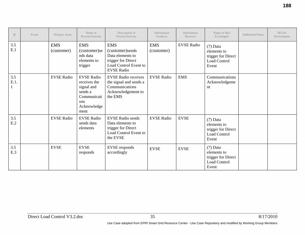
# Event Primary Actor Name of Process/Activity
Description of Process/Activity
Information Producer
Information Receiver
Name of Info Exchanged Additional Notes IECSA
Environment
3.5E.1
EMS (customer)
EMS (customer)sends data elements to trigger
EMS (customer)sends Data elements to trigger for Direct Load Control Event to EVSE Radio
EMS (customer)
EVSE Radio (7) Data elements to trigger for Direct Load Control Event
3.5E.1.1
EVSE Radio EVSE Radio receives the signal and sends a Communications Acknowledgement
EVSE Radio receives the signal and sends a Communications Acknowledgement to the EMS
EVSE Radio EMS Communications Acknowledgement
3.5E.2
EVSE Radio EVSE Radio sends data elements
EVSE Radio sends Data elements to trigger for Direct Load Control Event to the EVSE
EVSE Radio EVSE (7) Data elements to trigger for Direct Load Control Event
3.5E.3
EVSE EVSE responds
EVSE responds accordingly
EVSE EVSE (7) Data elements to trigger for Direct Load Control Event
Direct Load Control V3.2.doc 35 8/17/2010 Use Case adopted from EPRI Smart Grid Resource Center - Use Case Repository and modified by Working Group Members
188

# Event Primary Actor Name of Process/Activity
Description of Process/Activity
Information Producer
Information Receiver
Name of Info Exchanged Additional Notes IECSA
Environment
3.6 EMS (customer)
EMS (customer)collects and delivers Communication Acknowledgements
EMS (customer)collects and delivers Communication Acknowledgements to Internet Gateway
EMS (customer)
Internet Gateway
Communication Acknowledgements
3.7 Internet Gateway
Internet Gateway delivers Communication Acknowledgements
Internet Gateway delivers Communication Acknowledgements to the DR Application via the Internet Gateway
Internet Gateway
DR Application
Communication Acknowledgements
3.8 DR Application
DR Application displays updates
DR Application displays updates
DR Application
DR Application
System Updates
2.3.3 Post-conditions and Significant Results
Actor/Activity Post-conditions Description and Results
Distribution Operations Load control event successfully implemented
Supplier of Demand Response Application
It is delivered as expected
Direct Load Control V3.2.doc 36 8/17/2010 Use Case adopted from EPRI Smart Grid Resource Center - Use Case Repository and modified by Working Group Members
189

2.4 Architectural Issues in Interactions Elaborate on all architectural issues in each of the steps outlined in each of the sequences above. Reference the Step by number.
2.5 Diagrams
Direct Load Control Scenario 1 Sequence Diagram
Direct Load Control V3.2.doc 37 8/17/2010 Use Case adopted from EPRI Smart Grid Resource Center - Use Case Repository and modified by Working Group Members
190

Direct Load Control Scenario 1 Activity Diagram
Direct Load Control V3.2.doc 38 8/17/2010 Use Case adopted from EPRI Smart Grid Resource Center - Use Case Repository and modified by Working Group Members
191

Direct Load Control Scenario 2 Sequence Diagram
Direct Load Control V3.2.doc 39 8/17/2010 Use Case adopted from EPRI Smart Grid Resource Center - Use Case Repository and modified by Working Group Members
192

Direct load Control Scenario 2 Activity Diagram
Direct Load Control V3.2.doc 40 8/17/2010 Use Case adopted from EPRI Smart Grid Resource Center - Use Case Repository and modified by Working Group Members
193

Direct Load Control Scenario 3 Sequence Diagram
Direct Load Control V3.2.doc 41 8/17/2010 Use Case adopted from EPRI Smart Grid Resource Center - Use Case Repository and modified by Working Group Members
194

Direct Load Control Scenario 3 Activity Diagram
Direct Load Control V3.2.doc 42 8/17/2010 Use Case adopted from EPRI Smart Grid Resource Center - Use Case Repository and modified by Working Group Members
195

3 Auxiliary Issues
3.1 References and contacts Documents and individuals or organizations used as background to the function described; other functions referenced by this function, or acting as “sub” functions; or other documentation that clarifies the requirements or activities described. All prior work (intellectual property of the company or individual) or proprietary (non-publicly available) work must be so noted.
ID Title or contact Reference or contact information
[1]
3.2 Action Item List
ID Description Status
[1]
3.3 Revision History
No Date Author Description
1.1 3/22/2010 Brian D. Green Initial Use Case
1.2 3/24/2010 J.R. Cote Actor Name Review
1.3 3/30/2010 Brian D. Green Clean up Diagrams
2.0 4/11/2020 John J. Simmins Fill in some blanks
3.0 5/6/2010 Brian D. Green Minor Changes and add activity diagrams
Direct Load Control V3.2.doc 43 8/17/2010 Use Case adopted from EPRI Smart Grid Resource Center - Use Case Repository and modified by Working Group Members
196

Draft Use Cases – Preliminary in Nature
Volt VAR Optimization
197

American Electric Power 4.3 Distribution Grid Management
Document ID: Use case #
3.1
Title: Integrated Volt VAR Control Centralized
Subject Matter Expert: Author: Reviewed by: Ron Cunningham Brian D. Green Ron Cunningham
Copyright © 2011 American Electric Power Company
Integrated Volt VAR Control Centralized
Version History Rev. Date Author Change description
A 09/16/2011 Brian D. Green Initial Release B 10/31/2011 Ron Cunningham Final team review
"Acknowledgment: This material is based upon work supported by the Department of Energy under Award Number DE-OE0000193."
Disclaimer: "This report was prepared as an account of work sponsored by an agency of the United States Government. Neither the United States Government nor any agency thereof, nor any of their employees, makes any warranty, express or implied, or assumes any legal liability or responsibility for the accuracy, completeness, or usefulness of any information,
apparatus, product, or process disclosed, or represents that its use would not infringe privately owned rights. Reference herein to any specific commercial product, process, or
service by trade name, trademark, manufacturer, or otherwise does not necessarily constitute or imply its endorsement, recommendation, or favoring by the United States Government or any agency thereof. The views and opinions of authors expressed herein do not necessarily
state or reflect those of the United States Government or any agency thereof."
Use Case adopted from EPRI Smart Grid Resource Center - Use Case Repository and modified by Working Group Members
198

American Electric Power 4.3 Distribution Grid Management
Document ID: Use case #
3.1
Title: Integrated Volt VAR Control Centralized
Subject Matter Expert: Author: Reviewed by: Ron Cunningham Brian D. Green Ron Cunningham
Page 2 of 11 Copyright © 2011 American Electric Power Company Rev. 2
Summary:
The centralized Integrated Volt VAR Centralized (IVVC) system is an integral part of the Distribution SCADA (D-SCADA) environment. One central system manages and controls all Volt VAR Controller (VVC) devices on the regional distribution network.
Narrative:
The centralized Volt-VAR Controller (VVC) makes reference to the fact that in this centralized implementation, the VVC is completely integrated to Distribution SCADA (D-SCADA) and can only perform commands controlled by the D-SCADA system, (the intelligence of the Integrated Volt VAR Centralized (IVVC) lies within the D-SCADA system). The VVC devices inform the D-SCADA system of various measurements and statuses (including any Circuit Reconfiguration control area normal/abnormal state information associated with the Volt-VAR Control area), and the D-SCADA systems aggregate this information with Distribution RTU data it acquired from the field. The Powerflow Module acquires its necessary loadflow information and passes it on to the D-SCADA. D-SCADA then computes and prepares commands and sequences that it sends to the Distribution RTUs. The Distribution RTUs then interacts with various feeder line devices (Capacitor Bank Controller(s), Voltage Regulator Controller(s), and End-of-Line Voltage Monitor(s) (EOL Volt Monitors)) to pass configuration information and current state information that optimizes power distribution and minimizes loss. The D-SCADA system passes the information to the Distribution Historian environment for future analysis.
Use Case adopted from EPRI Smart Grid Resource Center - Use Case Repository and modified by Working Group Members
199

American Electric Power 4.3 Distribution Grid Management
Document ID: Use case #
3.1
Title: Integrated Volt VAR Control Centralized
Subject Matter Expert: Author: Reviewed by: Ron Cunningham Brian D. Green Ron Cunningham
Page 3 of 11 Copyright © 2011 American Electric Power Company Rev. 2
Interface Diagram:
Operations
SubStation
D-SCADADistribution Historian
Field
Distribution RTU
Capacitor Bank Controller
Voltage Regulator Controller
End-of-Line Voltage Monitor
65 66 67
Substation
Volt-VAR Controller
Powerflow Module
61
71
80
81
Circuit Reconfiguration
Controller63
Note(s):
Specific Feeder Line Devices include Capacitor Bank Controller, Voltage Regulator Controller and End-of-Line Voltage Monitor.
Use Case adopted from EPRI Smart Grid Resource Center - Use Case Repository and modified by Working Group Members
200

American Electric Power 4.3 Distribution Grid Management
Document ID: Use case #
3.1
Title: Integrated Volt VAR Control Centralized
Subject Matter Expert: Author: Reviewed by: Ron Cunningham Brian D. Green Ron Cunningham
Page 4 of 11 Copyright © 2011 American Electric Power Company Rev. 2
Actor(s):
The list of the actors and the roles that are participating in this use case described in the table below.
Name Role description
Capacitor Bank Controller
Controller for the capacitor banks
Circuit Reconfiguration Controller
Controller for the circuit reconfiguration system (logic and application)
Distribution Historian Data Historian for the distribution system
Distribution RTU Distribution RTU
D-SCADA Distribution SCADA
End-of-Line Voltage Monitor
Voltage monitors for endpoints at the end of the line.
Powerfow Module Loadflow calculation engine
Volt VAR Controller Controller for Volt VAR operation
Voltage Regulator Controller
Controller for the voltage regulators
Participating Business Functions:
The participating business function, its acronym and what they provide in this use case are detailed in the table below.
Acronym Business Function/Abstract Component Services or Information Provided
VVC Volt-VAR Controller, controls Volt VAR operations for the field equipment
Controls Volt VAR operations by initiating operational commands for field devices
CRC Circuit Reconfiguration Controller, controls fault isolation and circuit reconfiguration for the substation circuits
Circuit Reconfiguration control logic and application, initiating operational commands for fault isolation and reconfiguration devices
Use Case adopted from EPRI Smart Grid Resource Center - Use Case Repository and modified by Working Group Members
201

American Electric Power 4.3 Distribution Grid Management
Document ID: Use case #
3.1
Title: Integrated Volt VAR Control Centralized
Subject Matter Expert: Author: Reviewed by: Ron Cunningham Brian D. Green Ron Cunningham
Page 5 of 11 Copyright © 2011 American Electric Power Company Rev. 2
Assumptions / Design Considerations:
• Standard International Electrotechnical Commission (IEC) 61968 Message Definition format will be followed to provide the Header, Request, Reply, and payload used when defining the messages for the design specifications. For the purpose of this use case, no IEC 61968 or 61850 protocol messages are specified.
• Interoperability between AMI and real time grid management is challenged. Currently, metering standards and DNP3 are not compatible and AMI performance does not meet requirements of real time grid management.
• Work is still underway to see if the communications will be synchronous or asynchronous.
• This use case will portray the communications as asynchronous. It may need to be changed at a later date.
• Powerflow Module is up to date with the current as operated system configuration.
• Integrated Volt-VAR Control documented in this use case requires that the Circuit Reconfiguration control area (circuits) that the Integrated Volt-VAR Control circuit devices operate in, is in the normal circuit configuration state.
• This use case does not currently document the scenario of Integrated Volt-VAR Control being disabled (revert VVC controlled devices to their normal baseline state) upon recent of a Circuit Reconfiguration control area in abnormal state for those circuits with Integrated Volt-VAR Control nor the return to normal Volt-VAR Control operations.
Normal Sequence:
The sequences of events, showing the order in which they ocurr during the typical progression of this use case are provided in the table below. The Sequence Diagram that graphically depicts the events is presented immediately following the table.
Use Case Step
Triggering Event
Description Of Process Information To Be Exchanged
Producer Receiver Message Type
1 Predetermined and/or variable D-SCADA polling frequency
D-SCADA on a predetermined and or variable frequency will poll the Distribution RTU of specified Feeder Devices
Poll of Distribution RTU
D-SCADA
Distribution RTU
DNP3
2 On a predetermined frequency Distribution RTU will Poll of specified Feeder Devices
Poll of specified Feeder Devices
Distribution RTU
Feeder Device
DNP3
Use Case adopted from EPRI Smart Grid Resource Center - Use Case Repository and modified by Working Group Members
202

American Electric Power 4.3 Distribution Grid Management
Document ID: Use case #
3.1
Title: Integrated Volt VAR Control Centralized
Subject Matter Expert: Author: Reviewed by: Ron Cunningham Brian D. Green Ron Cunningham
Page 6 of 11 Copyright © 2011 American Electric Power Company Rev. 2
Use Case Step
Triggering Event
Description Of Process Information To Be Exchanged
Producer Receiver Message Type
3 Receipt of Poll Request or Time Trigger
Voltage Regulator Controller sends System Monitoring Data to Distribution RTU
System Monitoring Data
Voltage Regulator Controller
Distribution RTU
DNP3
4 Receipt of Poll Request or Time Trigger
Capacitor Bank Controller sends System Monitoring Data to D-RTU Distribution RTU
System Monitoring Data
Capacitor Bank Controller
Distribution RTU
DNP3
5 Receipt of Poll Request or Time Trigger
End–of-Line Voltage Monitor sends System Monitoring Data to Distribution RTU
System Monitoring Data
End-of-Line Voltage Monitor
Distribution RTU
DNP3
6 Change of State
Circuit Reconfiguration Controller sends Normal/Abnormal Status to Distribution RTU
Circuit Reconfiguration Control area Normal /Abnormal Status
Circuit Reconfiguration Controller
Distribution RTU
DNP3
7 Distribution RTU sends System Monitoring Data and CRC State Change to D-SCADA
System Monitoring Data & CRC Normal/Abnormal Status
Distribution RTU
D-SCADA
DNP3
8 D-SCADA sends System Monitoring Data to Volt-VAR Controller
System Monitoring Data from D-SCADA
D-SCADA
VVC DNP3
9 D-SCADA sends System Data to Distribution Historian on predetermined interval
System Data D-SCADA
Distribution Historian
Proprietary
10 Powerflow Module receives instruction to perform loadflow
Powerflow Module exchanges System Data with D-SCADA
System Data Powerflow Module
D-SCADA
DNP3
Use Case adopted from EPRI Smart Grid Resource Center - Use Case Repository and modified by Working Group Members
203

American Electric Power 4.3 Distribution Grid Management
Document ID: Use case #
3.1
Title: Integrated Volt VAR Control Centralized
Subject Matter Expert: Author: Reviewed by: Ron Cunningham Brian D. Green Ron Cunningham
Page 7 of 11 Copyright © 2011 American Electric Power Company Rev. 2
Use Case Step
Triggering Event
Description Of Process Information To Be Exchanged
Producer Receiver Message Type
11 Powerflow Module exchanges System Data with VVC via D-SCADA
System Data Powerflow Module
D-SCADA
Proprietary
12 D-SCADA exchanges Powerflow Module System Data with VVC
System Data D-SCADA
VVC DNP3
13 Receives loadflow and device status information
VVC calculates an Optimal Volt-VAR Configuration for the circuit and commands sequence (excluding circuit switching operations) to be initiated
Optimal Volt-VAR Configuration
VVC Internal Proprietary
14 VVC determines feeder line device operations needed
VVC issues Device Control/Commands to D-SCADA.
Device Control /Commands
VVC D-SCADA
DNP3
15 D-SCADA sends Device Control /Commands to Distribution RTU
Device Control /Commands
D-SCADA
Distribution RTU
DNP3
16 Distribution RTU issues Device Control /Commands to Voltage Regulator Controller.
Device Control /Commands
Distribution RTU
VVC DNP3
17 Receipt of control commands
Voltage Regulator Controller functions accordingly
Device Control /Commands
Voltage Regulator Controller
Internal Proprietary
Use Case adopted from EPRI Smart Grid Resource Center - Use Case Repository and modified by Working Group Members
204

American Electric Power 4.3 Distribution Grid Management
Document ID: Use case #
3.1
Title: Integrated Volt VAR Control Centralized
Subject Matter Expert: Author: Reviewed by: Ron Cunningham Brian D. Green Ron Cunningham
Page 8 of 11 Copyright © 2011 American Electric Power Company Rev. 2
Use Case Step
Triggering Event
Description Of Process Information To Be Exchanged
Producer Receiver Message Type
18 Distribution RTU issues Device Control /Commands to Capacitor Bank Controller
Device Control /Commands
Distribution RTU
Capacitor Bank Controller
DNP3
19 Receipt of control commands
Capacitor Bank Controller functions accordingly
Device Control /Commands
Capacitor Bank Controller
Internal Proprietary
20 Distribution RTU issues Device Control /Commands to End-of-Line Voltage Monitor
Device Control /Commands
Distribution RTU
End-of-Line Voltage Monitor
DNP3
21 Receipt of control commands
End-of-Line Voltage Monitor function accordingly
Device Control /Commands
End-of-Line Voltage Monitor
Internal Proprietary
22 D-SCADA on a predetermined and/or variable frequency will poll the Distribution RTUs of specified Feeder Devices
Poll of Distribution RTU
D-SCADA
Distribution RTU
DNP3
23 On a predetermined frequency Distribution RTUs will Poll of specified Feeder Devices
Poll of Specified Feeder Devices
Distribution RTU
Feeder Device
DNP3
24 D-SCADA sends System Data to Distribution Historian on predetermined interval
System Data D-SCADA
Distribution Historian
Proprietary
Use Case adopted from EPRI Smart Grid Resource Center - Use Case Repository and modified by Working Group Members
205

American Electric Power 4.3 Distribution Grid Management
Document ID: Use case #
3.1
Title: Integrated Volt VAR Control Centralized
Subject Matter Expert: Author: Reviewed by: Ron Cunningham Brian D. Green Ron Cunningham
Page 9 of 11 Copyright © 2011 American Electric Power Company Rev. 2
Use Case adopted from EPRI Smart Grid Resource Center - Use Case Repository and modified by Working Group Members
206

American Electric Power 4.3 Distribution Grid Management
Document ID: Use case #
3.1
Title: Integrated Volt VAR Control Centralized
Subject Matter Expert: Author: Reviewed by: Ron Cunningham Brian D. Green Ron Cunningham
Page 10 of 11 Copyright © 2011 American Electric Power Company Rev. 2
Integration Scenarios:
The following are the points of integration that must be tested for this use case. Other non-CIM message interfaces may be testable in this use case.
Actor Interface Points
D-SCADA
• Distribution RTU • Circuit Reconfiguration Controller • Volt-VAR Controller • Distribtuion Historian • Powerflow Module
Distribtuion RTU • Voltage Regulator Controller • Capacitor Bank Controller • End-of-Line Voltage Monitor
Pre-conditions: None
Post-conditions: None
Exceptions / Alternate Sequences:
There are no exceptions, unusual events or alternate sequences defined for this use case.
Use Case Step
Triggering Event
Description Of Process Information To Be Exchanged
Producer Receiver Message Type
Message Type(s) Diagram: None
An XML Schema Definition (XSD) diagram shows the normative and informative parts of the message. Not all of the International Electrotechnical Commission’s (IEC) – CIM message optional elements must or will be used in the use of IEC – CIM for this specific use case.
Use Case adopted from EPRI Smart Grid Resource Center - Use Case Repository and modified by Working Group Members
207

American Electric Power 4.3 Distribution Grid Management
Document ID: Use case #
3.1
Title: Integrated Volt VAR Control Centralized
Subject Matter Expert: Author: Reviewed by: Ron Cunningham Brian D. Green Ron Cunningham
Page 11 of 11 Copyright © 2011 American Electric Power Company Rev. 2
References:
Use Cases or other documentation referenced by this use case include:
• 20100625 AEP Ohio Interoperability Plan V1.docx: Section 4.3.2 (Centralized Integrated Volt/Var Control)
• 20100625 Use Cases EPRI Report_V2.4.docx: Section 3.1 (IVVC Centralized)
Issues: None
ID Description Status
Miscellaneous Notes: None
Use Case adopted from EPRI Smart Grid Resource Center - Use Case Repository and modified by Working Group Members
208

Appendix D P2030 Conceptual Architectural Diagrams
The IEEE P2030 Smart Grid Interoperability Standard architectural diagram was used as a way to conceptualize the DSPP. The integration and interfaces of energy technologies, information technologies, and communication technologies are necessary to achieve seamless distributed grid operations and market functions. The standard covers all major areas of the DSPP; Power Control, Information Technology, and Communications with cross-cutting elements of data, integration, and security.
The following diagrams are examples of use cases, e.g., functions, which the DSPP could facilitate. The entities and interfaces required to facilitate these DSPP functions for the specific use case are highlighted in yellow. All examples are preliminary in nature and are for illustrative purposes only.
All materials are adapted and reprinted with permission from IEEE.
209

Dynamic Electricity Production Forecasting
210

cat
IT Layer Use Case - Dynamic Electricity Production forecasting
DistributionManagement IT27
DistributedEnergy
Resources(Local
Generation)
GeographicInformation
Management
IT34
EnergyMarket
Clearing
IT36
DistributionOperation
IT13
Adapted and reprinted with permission from IEEE. Copyright IEEE 2011. All rights reserved
211

Use Case - Dynamic Electricity Production forecasting
Power Layer- Use Case - Dynamic Electricity Production forecasting
Adapted and reprinted with permission from IEEE. Copyright IEEE 2011. All rights reserved
212

Adapted and reprinted with permission from IEEE. Copyright IEEE 2011. All rights reserved
Comms Layer Use Case - Dynamic Electricity Production forecasting
213

Direct Load Control
214

Adapted and reprinted with permission from IEEE. Copyright IEEE 2011. All rights reserved
IT Layer Use Case – Direct Load Control
215

Adapted and reprinted with permission from IEEE. Copyright IEEE 2011. All rights reserved
Power Layer Use Case – Direct Load Control
216

Adapted and reprinted with permission from IEEE. Copyright IEEE 2011. All rights reserved
Comms Layer Use Case – Direct Load Control
217

Volt VAR Optimization
218

Adapted and reprinted with permission from IEEE. Copyright IEEE 2011. All rights reserved
IT Layer Use Case – VVO (Volt VAR Optimization)
219

Adapted and reprinted with permission from IEEE. Copyright IEEE 2011. All rights reserved
Power Layer Use Case – VVO (Volt VAR Optimization)
220

Adapted and reprinted with permission from IEEE. Copyright IEEE 2011. All rights reserved
Comm Layer Use Case – VVO (Volt VAR Optimization)
221

Appendix E
Draft of Technology Matrix Mapping Tool – Preliminary in Nature
See excel workbook titled “Appendix E”.
222


![74972819 Manual Vision Estrategica Rev 180911 3[1]](https://img.pdfslide.net/doc/110x75/5572002549795991699ee2d3/74972819-manual-vision-estrategica-rev-180911-31.jpg)