Embed Size (px)
Citation preview
User’s Manual
Refrigerated Circulators
Manual P/N U00971Rev. 02/14/08
- 1 -
PolyStat® Refrigerated CirculatorInstruction and Operation Manual
PrefaceCompliance ............................................................ 3Unpacking .............................................................. 3Warranty ................................................................ 3
SafetyWarnings................................................................ 4
General InformationDescription ............................................................. 5Specifications ........................................................ 5
InstallationSite ........................................................................ 6Electrical Requirements ......................................... 7Plumbing Requirements ........................................ 8Fluids ..................................................................... 9Filling Requirements ............................................. 9
OperationControllers ........................................................... 10Start Up ................................................................ 10
Digital ControllerMain Display ........................................................ 11Key Button Definition ........................................... 11Viewing Setpoint .................................................. 11Changing Setpoint ............................................... 11Setup Loop .......................................................... 12Calibration Loop ................................................... 13
Advanced Digital Controller
Main Display ........................................................ 14Key Button Definition ........................................... 14Changing Setpoint ............................................... 14Viewing Setpoint .................................................. 14Setup Loop .......................................................... 15Calibration Loop ................................................... 16
- 2 -
ProgrammableController
Main Display ........................................................ 17Key Button Definition ........................................... 17Changing Setpoint ............................................... 18Programming Loop .............................................. 18Setup Loop .......................................................... 19Calibration Loop ................................................... 21Sample Program .................................................. 22
Additional FeaturesDB9 Connector Pinouts ....................................... 23RS-232 Serial Communications Protocol ............. 24High Temperature/Low Liquid Safety ................... 25
Maintenance &Troubleshooting
Cleaning ............................................................... 26Algae.................................................................... 26Checklist .............................................................. 26PID Values ........................................................... 27
AppendixWater Quality Standards and Recommendations
- 3 -
PrefaceCompliance
Products tested and found to be in compliance with the requirements definedin the EMC standards defined by 89/336/EEC as well as Low VoltageDirective (LVD) 73/23/EEC can be identified by the CE Mark on the rear ofthe unit. The testing has demonstrated compliance with the following direc-tives:
LVD, 73/23/EEC Complies with IEC/EN61010-1
EMC, 89/336/EEC IEC/EN61326-1
For any additional information, refer to the Declaration of Conformity thatshipped with the unit.
UnpackingRetain all cartons and packing material until the unit is operated and found tobe in good condition. If the unit shows external or internal damage contactthe transportation company and file a damage claim. Under ICC regulations,this is your responsibility.
WarrantyThe Cole-Parmer circulators distributed by Cole-Parmer, Cole-Parmerwarrants to the direct purchaser that the product will be free from defects inmaterial or workmanship for a period of two years from the date of delivery.Cole-Parmer will repair or replace the product or provide credit, as its soleoption, upon prompt notification and compliance with its instructions.
The Distributor warrants to Customer that upon prompt notification andcompliance with Distributor's instructions, that the Distributor will repair orreplace, at Distributor's sole option, any Product which is defective in mate-rial or workmanship.
Distributor expressly disclaims all other warranties, whether expressed,implied or statutory, including the warranties of merchantability, and fitnessfor a particular purpose. Distributor's sole responsibility and the Customer'sexclusive remedy for any claim arising out of the purchase of any Product isrepair or replacement, as described above. In no event shall Distributor'sliability exceed the purchase price pain therefor; nor shall Distributor be liablefor any claims, losses or damage of any third party or for lost profits or anyspecial, indirect, incidental, consequential, or exemplary damages, howso-ever arising, even if Distributor has been advised of the possibility of suchdamages.
- 4 -
SafetyWarnings
In addition to the safety warnings listed below, warnings are posted throughoutthe manual. These warnings are designated by an exclamation mark inside anequilateral triangle with text highlighted in bold print. Read and follow theseimportant instructions. Failure to observe these instructions can result inpermanent damage to the unit, significant property damage, personal injury ordeath.
The lightning flash with arrow symbol, within an equilateral triangle, isintended to alert the user to the presence of non-insulated "dangerousvoltage" within the unit's enclosure. The voltage may be of significant magni-tude to constitute a risk of electrical shock.
This label, engraved into the front of the tank lip, indicates the presence ofhot surfaces.
Make sure you read and understand all instructions and safety precautionslisted in this manual before installing or operating your unit. If you have anyquestions concerning the operation of your unit or the information in thismanual, contact our Sales Department.
Performance of installation, operation, or maintenance proceduresother than those described in this manual may result in a hazardoussituation and may void the manufacturer's warranty.
Transport the unit with care. Sudden jolts or drops can damage theunit's components.
Observe all warning labels.
Never remove warning labels.
Never operate damaged or leaking equipment.
Never operate the unit without fluid in the circulator.
Use water unless operating above 80°C or below 7°C. Above 80°C useDow 200 silicon oil. For operation below 7°C, a 50/50 mixture, by vol-ume, of filtered tap water and laboratory grade ethylene glycol issuggested.
Always turn off the unit and disconnect the line cord from the powersource before performing any service or maintenance procedures, orbefore moving the unit.
Always empty the circulator before moving the unit.
Never operate equipment with damaged line cords.
Refer service and repairs to a qualified technician.
- 5 -
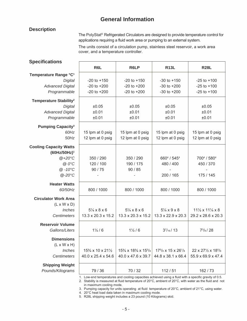
SpecificationsR6L R6LP R13L R28L
Temperature Range °C1
Digital -20 to +150 -20 to +150 -30 to +150 -25 to +100Advanced Digital -20 to +200 -20 to +200 -30 to +200 -25 to +100
Programmable -20 to +200 -20 to +200 -30 to +200 -25 to +100
Temperature Stability2
Digital ±0.05 ±0.05 ±0.05 ±0.05Advanced Digital ±0.01 ±0.01 ±0.01 ±0.01
Programmable ±0.01 ±0.01 ±0.01 ±0.01
Pumping Capacity3
60Hz 15 lpm at 0 psig 15 lpm at 0 psig 15 lpm at 0 psig 15 lpm at 0 psig50Hz 12 lpm at 0 psig 12 lpm at 0 psig 12 lpm at 0 psig 12 lpm at 0 psig
Cooling Capacity Watts(60Hz/50Hz)1
@+20°C 350 / 290 350 / 290 6604 / 5454 7004 / 5804
@ 0°C 120 / 100 190 / 175 480 / 400 450 / 370@ -10°C 90 / 75 90 / 85 - -@-20°C - - 200 / 165 175 / 145
Heater Watts60/50Hz 800 / 1000 800 / 1000 800 / 1000 800 / 1000
Circulator Work Area(L x W x D)
Inches 5¼ x 8 x 6 5¼ x 8 x 6 5¼ x 9 x 8 11½ x 11¼ x 8Centimeters 13.3 x 20.3 x 15.2 13.3 x 20.3 x 15.2 13.3 x 22.9 x 20.3 29.2 x 28.6 x 20.3
Reservoir VolumeGallons/Liters 1½ / 6 1½ / 6 37/16 / 13 73/8 / 28
Dimensions(L x W x H)
Inches 15¾ x 10 x 21½ 15¾ x 18¾ x 155/8 175/8 x 15 x 261/8 22 x 27½ x 185/8
Centimeters 40.0 x 25.4 x 54.6 40.0 x 47.6 x 39.7 44.8 x 38.1 x 66.4 55.9 x 69.9 x 47.4
Shipping WeightPounds/Kilograms 79 / 36 70 / 32 112 / 51 162 / 73
General InformationDescription
The PolyStat® Refrigerated Circulators are designed to provide temperature control forapplications requiring a fluid work area or pumping to an external system.The units consist of a circulation pump, stainless steel reservoir, a work areacover, and a temperature controller.
1. Low-end temperatures and cooling capacities achieved using a fluid with a specific gravity of 0.5.2. Stability is measured at fluid temperature of 20°C, ambient of 20°C, with water as the fluid and not
in maximum cooling mode.3. Pumping capacity for units operating at fluid temperature of 20°C, ambient of 21°C, using water.4. 20°C heat load data taken in maximum cooling mode.5. R28L shipping weight includes a 23 pound (10 Kilograms) skid.
- 6 -
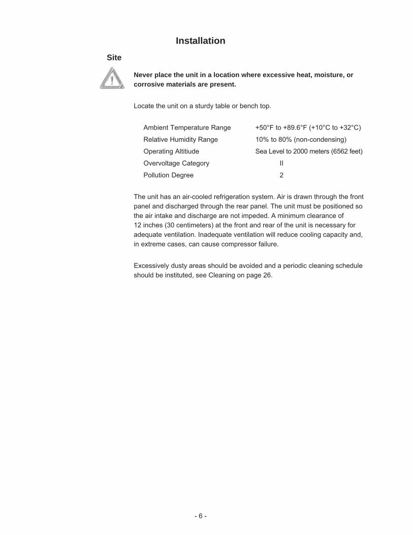
InstallationSite
Never place the unit in a location where excessive heat, moisture, orcorrosive materials are present.
Locate the unit on a sturdy table or bench top.
Ambient Temperature Range +50°F to +89.6°F (+10°C to +32°C)
Relative Humidity Range 10% to 80% (non-condensing)
Operating Altitiude Sea Level to 2000 meters (6562 feet)
Overvoltage Category II
Pollution Degree 2
The unit has an air-cooled refrigeration system. Air is drawn through the frontpanel and discharged through the rear panel. The unit must be positioned sothe air intake and discharge are not impeded. A minimum clearance of12 inches (30 centimeters) at the front and rear of the unit is necessary foradequate ventilation. Inadequate ventilation will reduce cooling capacity and,in extreme cases, can cause compressor failure.
Excessively dusty areas should be avoided and a periodic cleaning scheduleshould be instituted, see Cleaning on page 26.
- 7 -
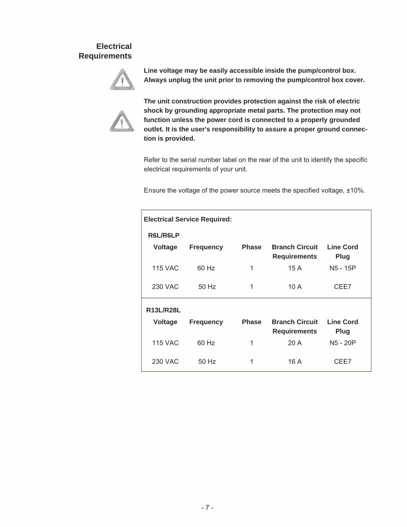
Electrical Service Required:
R6L/R6LP
Voltage Frequency Phase Branch Circuit Line CordRequirements Plug
115 VAC 60 Hz 1 15 A N5 - 15P
230 VAC 50 Hz 1 10 A CEE7
R13L/R28L
Voltage Frequency Phase Branch Circuit Line CordRequirements Plug
115 VAC 60 Hz 1 20 A N5 - 20P
230 VAC 50 Hz 1 16 A CEE7
ElectricalRequirements
Line voltage may be easily accessible inside the pump/control box.Always unplug the unit prior to removing the pump/control box cover.
The unit construction provides protection against the risk of electricshock by grounding appropriate metal parts. The protection may notfunction unless the power cord is connected to a properly groundedoutlet. It is the user's responsibility to assure a proper ground connec-tion is provided.
Refer to the serial number label on the rear of the unit to identify the specificelectrical requirements of your unit.
Ensure the voltage of the power source meets the specified voltage, ±10%.
- 8 -
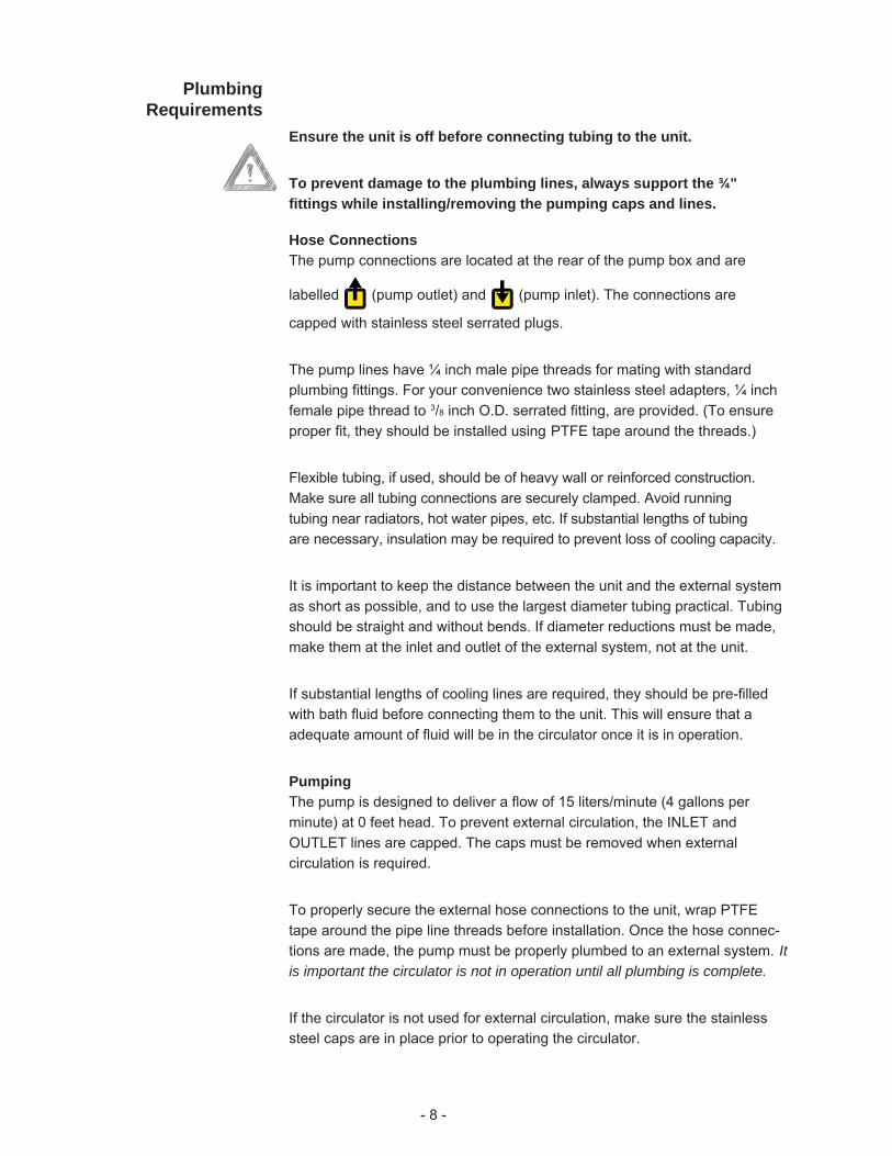
PlumbingRequirements
Ensure the unit is off before connecting tubing to the unit.
To prevent damage to the plumbing lines, always support the ¾"fittings while installing/removing the pumping caps and lines.
Hose ConnectionsThe pump connections are located at the rear of the pump box and are
labelled (pump outlet) and (pump inlet). The connections are
capped with stainless steel serrated plugs.
The pump lines have ¼ inch male pipe threads for mating with standardplumbing fittings. For your convenience two stainless steel adapters, ¼ inchfemale pipe thread to 3/8 inch O.D. serrated fitting, are provided. (To ensureproper fit, they should be installed using PTFE tape around the threads.)
Flexible tubing, if used, should be of heavy wall or reinforced construction.Make sure all tubing connections are securely clamped. Avoid runningtubing near radiators, hot water pipes, etc. If substantial lengths of tubingare necessary, insulation may be required to prevent loss of cooling capacity.
It is important to keep the distance between the unit and the external systemas short as possible, and to use the largest diameter tubing practical. Tubingshould be straight and without bends. If diameter reductions must be made,make them at the inlet and outlet of the external system, not at the unit.
If substantial lengths of cooling lines are required, they should be pre-filledwith bath fluid before connecting them to the unit. This will ensure that aadequate amount of fluid will be in the circulator once it is in operation.
PumpingThe pump is designed to deliver a flow of 15 liters/minute (4 gallons perminute) at 0 feet head. To prevent external circulation, the INLET andOUTLET lines are capped. The caps must be removed when externalcirculation is required.
To properly secure the external hose connections to the unit, wrap PTFEtape around the pipe line threads before installation. Once the hose connec-tions are made, the pump must be properly plumbed to an external system. Itis important the circulator is not in operation until all plumbing is complete.
If the circulator is not used for external circulation, make sure the stainlesssteel caps are in place prior to operating the circulator.
- 9 -
Fluids
Never use flammable or corrosive fluids with this unit.
Water is the recommended fluid for operation from +7°C to +80°C, see theAppendix.
Dow 200 silicon oil is recommended for operation above +80°C.
Due to potential fire hazard, do not use any other fluid above +80°C.
For operation below +7°C, a 50/50 mixture, by volume, of laboratory gradeethylene glycol and filtered tap water is suggested.
Never use pure ethylene glycol as a fluid. A maximum 80/20 mixture ofethylene glycol and filtered tap water is allowed.
FillingRequirements
The circulator work area has a high and low level marker to guide filling. Themarkers are 1 inch horizontal slits located in the center of the stainless steelbaffle separating the work area and the pump assembly. The correct fluidlevel falls between these two markers. The heating and cooling coils will beexposed and may become damaged if the correct fluid level is not provided.
When pumping to an external system, keep extra fluid on hand to maintainthe proper level in both the circulating lines and external system.
Never run the unit when the work area is empty.
When using Dow 200-50, ensure the work area contains no waterbefore filling the unit.
Dow 200-50 fluid will expand when heated.
- 10 -
OperationControllers
Three temperature controllers are available with the unit: Digital, AdvancedDigital and Programmable. This section explains these three controllers.
Start UpBefore starting the unit, check all electrical and plumbing connections andmake sure the work area has been properly filled with fluid.
To start any unit place the I/O switch on the side of the controller to theI (power on) position. The pump will start and the controller display will light.
For units with the Digital Controller the refrigeration is manually controlled bythe ON/OFF switch on the side of the control box.
For units with standard controllers, the refrigeration is manually controlled bythe ON/OFF switch on the side of the control box. In addition, units R13L andR28L have HI/LO refrigeration control. For optimal cooling, use HI whenoperating at 20°C or below, otherwise use LO.
The refrigeration system is not designed to operate above 35°C. Whenoperating above 35°C ensure that the refrigeration is turned off.
If the FAULT light is illuminated see page 25.
NOTE: When the unit is shut off, wait approximately five minutes beforerestarting. This allows time for the refrigeration pressures to equalize. If thepressures are not allowed to equalize, the compressor will short-cycle(clicking sound) and no cooling will occur.
- 11 -
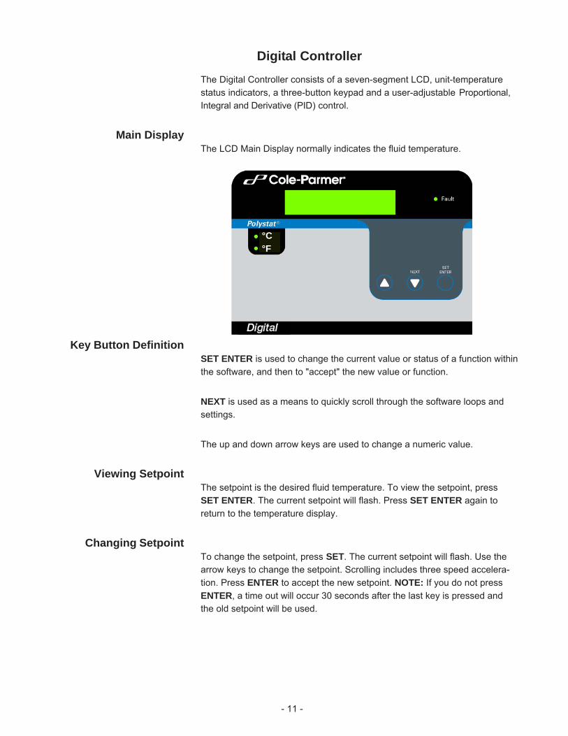
Digital ControllerThe Digital Controller consists of a seven-segment LCD, unit-temperaturestatus indicators, a three-button keypad and a user-adjustable Proportional,Integral and Derivative (PID) control.
Main DisplayThe LCD Main Display normally indicates the fluid temperature.
Key Button DefinitionSET ENTER is used to change the current value or status of a function withinthe software, and then to "accept" the new value or function.
NEXT is used as a means to quickly scroll through the software loops andsettings.
The up and down arrow keys are used to change a numeric value.
Viewing SetpointThe setpoint is the desired fluid temperature. To view the setpoint, pressSET ENTER. The current setpoint will flash. Press SET ENTER again toreturn to the temperature display.
Changing SetpointTo change the setpoint, press SET. The current setpoint will flash. Use thearrow keys to change the setpoint. Scrolling includes three speed accelera-tion. Press ENTER to accept the new setpoint. NOTE: If you do not pressENTER, a time out will occur 30 seconds after the last key is pressed andthe old setpoint will be used.
°C°F
- 12 -
Pxx.x
I x.xx
Dx.xx
unit
NEX
T ke
y
MAIN DISPLAY
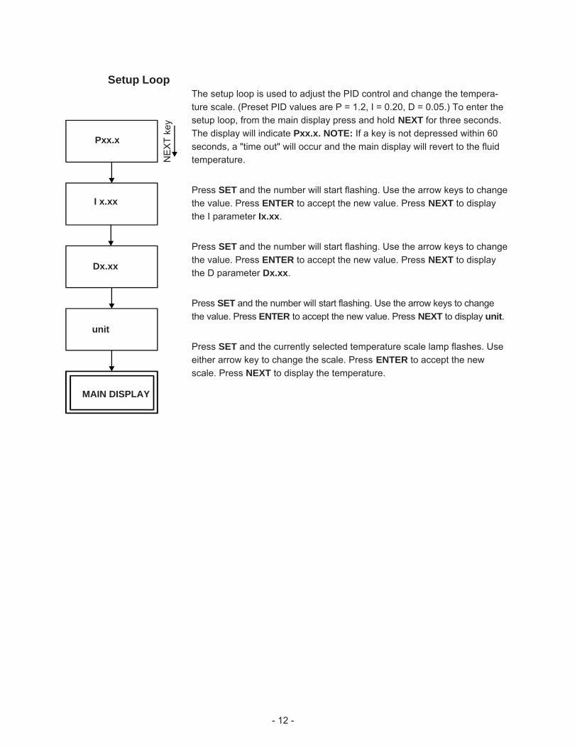
Setup LoopThe setup loop is used to adjust the PID control and change the tempera-ture scale. (Preset PID values are P = 1.2, I = 0.20, D = 0.05.) To enter thesetup loop, from the main display press and hold NEXT for three seconds.The display will indicate Pxx.x. NOTE: If a key is not depressed within 60seconds, a "time out" will occur and the main display will revert to the fluidtemperature.
Press SET and the number will start flashing. Use the arrow keys to changethe value. Press ENTER to accept the new value. Press NEXT to displaythe I parameter Ix.xx.
Press SET and the number will start flashing. Use the arrow keys to changethe value. Press ENTER to accept the new value. Press NEXT to displaythe D parameter Dx.xx.
Press SET and the number will start flashing. Use the arrow keys to changethe value. Press ENTER to accept the new value. Press NEXT to display unit.
Press SET and the currently selected temperature scale lamp flashes. Useeither arrow key to change the scale. Press ENTER to accept the newscale. Press NEXT to display the temperature.
- 13 -
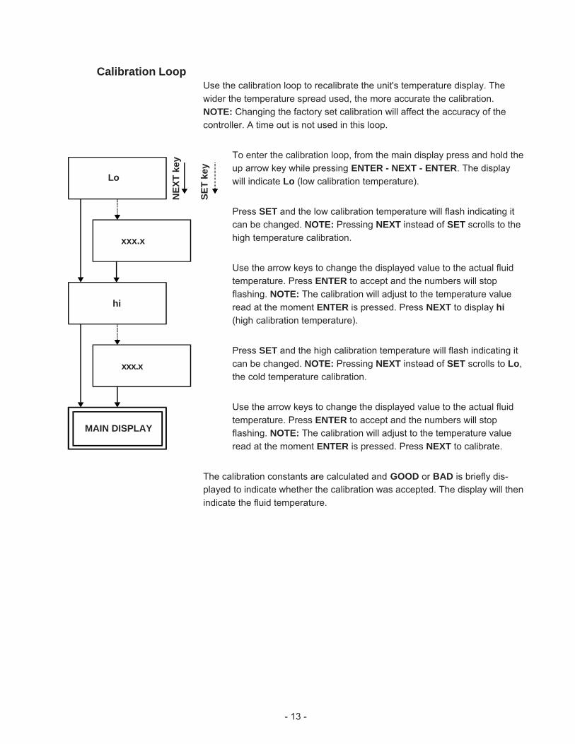
Calibration LoopUse the calibration loop to recalibrate the unit's temperature display. Thewider the temperature spread used, the more accurate the calibration.NOTE: Changing the factory set calibration will affect the accuracy of thecontroller. A time out is not used in this loop.
To enter the calibration loop, from the main display press and hold theup arrow key while pressing ENTER - NEXT - ENTER. The displaywill indicate Lo (low calibration temperature).
Press SET and the low calibration temperature will flash indicating itcan be changed. NOTE: Pressing NEXT instead of SET scrolls to thehigh temperature calibration.
Use the arrow keys to change the displayed value to the actual fluidtemperature. Press ENTER to accept and the numbers will stopflashing. NOTE: The calibration will adjust to the temperature valueread at the moment ENTER is pressed. Press NEXT to display hi(high calibration temperature).
Press SET and the high calibration temperature will flash indicating itcan be changed. NOTE: Pressing NEXT instead of SET scrolls to Lo,the cold temperature calibration.
Use the arrow keys to change the displayed value to the actual fluidtemperature. Press ENTER to accept and the numbers will stopflashing. NOTE: The calibration will adjust to the temperature valueread at the moment ENTER is pressed. Press NEXT to calibrate.
The calibration constants are calculated and GOOD or BAD is briefly dis-played to indicate whether the calibration was accepted. The display will thenindicate the fluid temperature.
xxx.x
hi
xxx.x
Lo
MAIN DISPLAY
NEX
T ke
y
SET
key
- 14 -
Advanced Digital ControllerMain Display
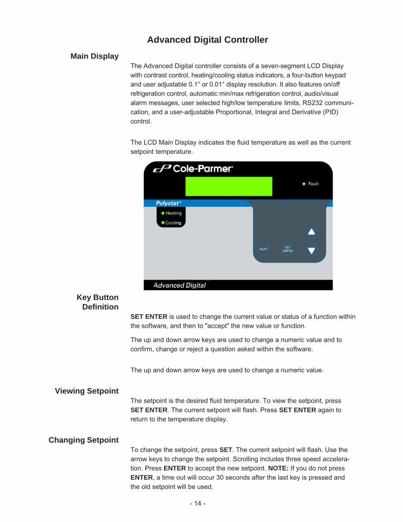
The Advanced Digital controller consists of a seven-segment LCD Displaywith contrast control, heating/cooling status indicators, a four-button keypadand user adjustable 0.1° or 0.01° display resolution. It also features on/offrefrigeration control, automatic min/max refrigeration control, audio/visualalarm messages, user selected high/low temperature limits, RS232 communi-cation, and a user-adjustable Proportional, Integral and Derivative (PID)control.
The LCD Main Display indicates the fluid temperature as well as the currentsetpoint temperature.
Key ButtonDefinition
SET ENTER is used to change the current value or status of a function withinthe software, and then to "accept" the new value or function.
The up and down arrow keys are used to change a numeric value and toconfirm, change or reject a question asked within the software.
The up and down arrow keys are used to change a numeric value.
Viewing SetpointThe setpoint is the desired fluid temperature. To view the setpoint, pressSET ENTER. The current setpoint will flash. Press SET ENTER again toreturn to the temperature display.
Changing SetpointTo change the setpoint, press SET. The current setpoint will flash. Use thearrow keys to change the setpoint. Scrolling includes three speed accelera-tion. Press ENTER to accept the new setpoint. NOTE: If you do not pressENTER, a time out will occur 30 seconds after the last key is pressed andthe old setpoint will be used.
- 15 -
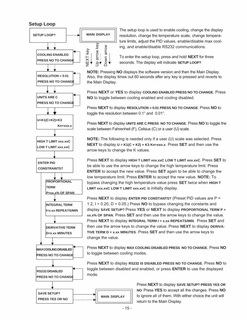
Setup LoopThe setup loop is used to enable cooling, change the displayresolution, change the temperature scale, change tempera-ture limits, adjust the PID values, enable/disable max cool-ing, and enable/disable RS232 communications.
To enter the setup loop, press and hold NEXT for threeseconds. The display will indicate SETUP LOOP?
NOTE: Pressing NO displays the software version and then the Main Display.Also, the display times out 60 seconds after any key is pressed and reverts tothe Main Display.
Press NEXT or YES to display COOLING ENABLED PRESS NO TO CHANGE. PressNO to toggle between cooling enabled and cooling disabled.
Press NEXT to display RESOLUTION = 0.01 PRESS NO TO CHANGE. Press NO totoggle the resolution between 0.1° and 0.01°.
Press NEXT to display UNITS ARE C PRESS NO TO CHANGE. Press NO to toggle thescale between Fahrenheit (F), Celsius (C) or a user (U) scale.
NOTE: The following is needed only if a user (U) scale was selected. PressNEXT to display U = K1(C + K2) + K3 Kn=xxx.x. Press SET and then use thearrow keys to change the K values.
Press NEXT to display HIGH T LIMIT xxx.xxC LOW T LIMIT xxx.xxC. Press SET tobe able to use the arrow keys to change the high temperature limit. PressENTER to accept the new value. Press SET again to be able to change thelow temperature limit. Press ENTER to accept the new value. NOTE: Tobypass changing the high temperature value press SET twice when HIGH TLIMIT xxx.xxC LOW T LIMIT xxx.xxC is initially display.
Press NEXT to display ENTER PID CONSTANTS? (Preset PID values are P =1.2, I = 0.20, D = 0.05.) Press NO to bypass changing the constants anddisplay SAVE SETUP? Press YES or NEXT to display PROPORTIONAL TERM P =xx.x% OF SPAN. Press SET and then use the arrow keys to change the value.Press NEXT to display INTEGRAL TERM I = x.xx REPEATS/MIN. Press SET andthen use the arrow keys to change the value. Press NEXT to display DERIVA-TIVE TERM D = x.xx MINUTES. Press SET and then use the arrow keys tochange the value.
Press NEXT to display MAX COOLING DISABLED PRESS NO TO CHANGE. Press NOto toggle between cooling modes.
Press NEXT to display RS232 IS DISABLED PRESS NO TO CHANGE. Press NO totoggle between disabled and enabled, or press ENTER to use the displayedmode.
Press NEXT to display SAVE SETUP? PRESS YES ORNO. Press YES to accept all the changes. Press NOto ignore all of them. With either choice the unit willreturn to the Main Display.
SAVE SETUP?
PRESS YES OR NO
MAX COOLING DISABLED
PRESS NO TO CHANGE
HIGH T LIMIT xxx.xxC
LOW T LIMIT xxx.xxC
U=K1(C+K2)+K3
Kn=xxx.x
SETUP LOOP?
NEX
T ke
y
Up
arro
w k
ey
Dow
n ar
row
RESOLUTION = 0.01
PRESS NO TO CHANGE
COOLING ENABLED
PRESS NO TO CHANGE
UNITS ARE C
PRESS NO TO CHANGE
ENTER PID
CONSTRAINTS?
INTEGRAL TERM
I=x.xx REPEATS/MIN
DERIVATIVE TERM
D=x.xx MINUTES
MAIN DISPLAY
PROPORTIONAL
TERM
P=xx.x% OF SPAN
MAIN DISPLAY
RS232 DISABLED
PRESS NO TO CHANGE
- 16 -
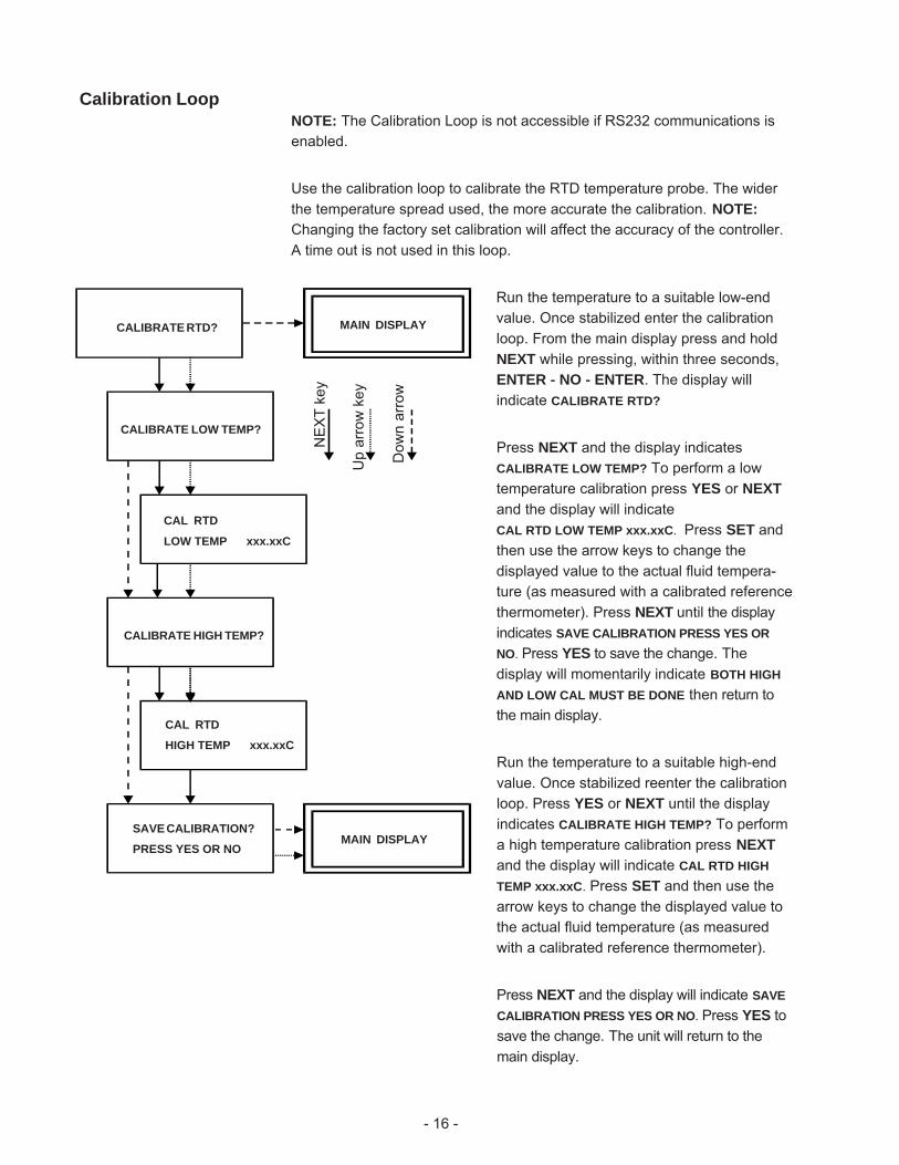
Calibration LoopNOTE: The Calibration Loop is not accessible if RS232 communications isenabled.
Use the calibration loop to calibrate the RTD temperature probe. The widerthe temperature spread used, the more accurate the calibration. NOTE:Changing the factory set calibration will affect the accuracy of the controller.A time out is not used in this loop.
Run the temperature to a suitable low-endvalue. Once stabilized enter the calibrationloop. From the main display press and holdNEXT while pressing, within three seconds,ENTER - NO - ENTER. The display willindicate CALIBRATE RTD?
Press NEXT and the display indicatesCALIBRATE LOW TEMP? To perform a lowtemperature calibration press YES or NEXTand the display will indicateCAL RTD LOW TEMP xxx.xxC. Press SET andthen use the arrow keys to change thedisplayed value to the actual fluid tempera-ture (as measured with a calibrated referencethermometer). Press NEXT until the displayindicates SAVE CALIBRATION PRESS YES ORNO. Press YES to save the change. Thedisplay will momentarily indicate BOTH HIGHAND LOW CAL MUST BE DONE then return tothe main display.
Run the temperature to a suitable high-endvalue. Once stabilized reenter the calibrationloop. Press YES or NEXT until the displayindicates CALIBRATE HIGH TEMP? To performa high temperature calibration press NEXTand the display will indicate CAL RTD HIGHTEMP xxx.xxC. Press SET and then use thearrow keys to change the displayed value tothe actual fluid temperature (as measuredwith a calibrated reference thermometer).
Press NEXT and the display will indicate SAVECALIBRATION PRESS YES OR NO. Press YES tosave the change. The unit will return to themain display.
CALIBRATE HIGH TEMP?
CALIBRATE RTD?
SAVE CALIBRATION?
PRESS YES OR NO
MAIN DISPLAYN
EXT
key
CALIBRATE LOW TEMP?
CAL RTD
LOW TEMP xxx.xxC
CAL RTD
HIGH TEMP xxx.xxC
MAIN DISPLAY
Up
arro
w k
ey
Dow
n ar
row
- 17 -
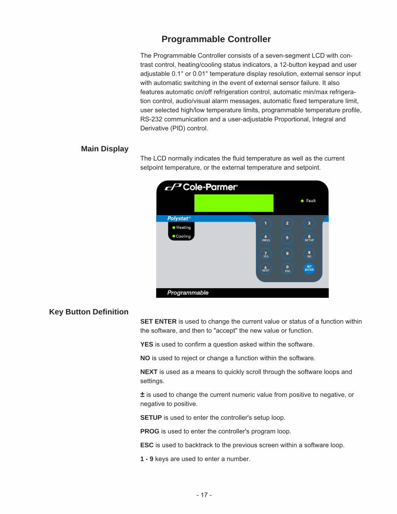
Programmable ControllerThe Programmable Controller consists of a seven-segment LCD with con-trast control, heating/cooling status indicators, a 12-button keypad and useradjustable 0.1° or 0.01° temperature display resolution, external sensor inputwith automatic switching in the event of external sensor failure. It alsofeatures automatic on/off refrigeration control, automatic min/max refrigera-tion control, audio/visual alarm messages, automatic fixed temperature limit,user selected high/low temperature limits, programmable temperature profile,RS-232 communication and a user-adjustable Proportional, Integral andDerivative (PID) control.
Main DisplayThe LCD normally indicates the fluid temperature as well as the currentsetpoint temperature, or the external temperature and setpoint.
Key Button DefinitionSET ENTER is used to change the current value or status of a function withinthe software, and then to "accept" the new value or function.
YES is used to confirm a question asked within the software.
NO is used to reject or change a function within the software.
NEXT is used as a means to quickly scroll through the software loops andsettings.
± is used to change the current numeric value from positive to negative, ornegative to positive.
SETUP is used to enter the controller's setup loop.
PROG is used to enter the controller's program loop.
ESC is used to backtrack to the previous screen within a software loop.
1 - 9 keys are used to enter a number.
- 18 -
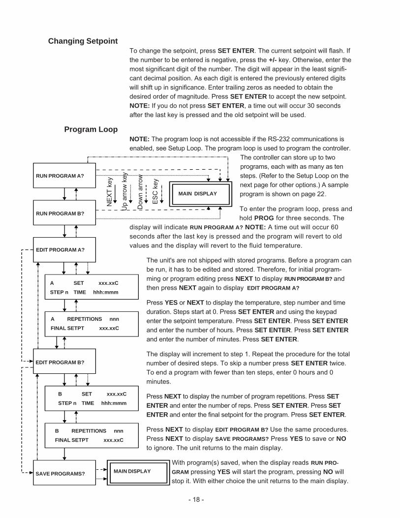
Changing SetpointTo change the setpoint, press SET ENTER. The current setpoint will flash. Ifthe number to be entered is negative, press the +/- key. Otherwise, enter themost significant digit of the number. The digit will appear in the least signifi-cant decimal position. As each digit is entered the previously entered digitswill shift up in significance. Enter trailing zeros as needed to obtain thedesired order of magnitude. Press SET ENTER to accept the new setpoint.NOTE: If you do not press SET ENTER, a time out will occur 30 secondsafter the last key is pressed and the old setpoint will be used.
Program LoopNOTE: The program loop is not accessible if the RS-232 communications isenabled, see Setup Loop. The program loop is used to program the controller.
The controller can store up to twoprograms, each with as many as tensteps. (Refer to the Setup Loop on thenext page for other options.) A sampleprogram is shown on page 22.
To enter the program loop, press andhold PROG for three seconds. The
display will indicate RUN PROGRAM A? NOTE: A time out will occur 60seconds after the last key is pressed and the program will revert to oldvalues and the display will revert to the fluid temperature.
The unit's are not shipped with stored programs. Before a program canbe run, it has to be edited and stored. Therefore, for initial program-ming or program editing press NEXT to display RUN PROGRAM B? andthen press NEXT again to display EDIT PROGRAM A?
Press YES or NEXT to display the temperature, step number and timeduration. Steps start at 0. Press SET ENTER and using the keypadenter the setpoint temperature. Press SET ENTER. Press SET ENTERand enter the number of hours. Press SET ENTER. Press SET ENTERand enter the number of minutes. Press SET ENTER.
The display will increment to step 1. Repeat the procedure for the totalnumber of desired steps. To skip a number press SET ENTER twice.To end a program with fewer than ten steps, enter 0 hours and 0minutes.
Press NEXT to display the number of program repetitions. Press SETENTER and enter the number of reps. Press SET ENTER. Press SETENTER and enter the final setpoint for the program. Press SET ENTER.
Press NEXT to display EDIT PROGRAM B? Use the same procedures.Press NEXT to display SAVE PROGRAMS? Press YES to save or NOto ignore. The unit returns to the main display.
With program(s) saved, when the display reads RUN PRO-GRAM pressing YES will start the program, pressing NO willstop it. With either choice the unit returns to the main display.
NEX
T ke
y
ES
C k
ey
RUN PROGRAM A?
RUN PROGRAM B?
EDIT PROGRAM A?
A SET xxx.xxC
STEP n TIME hhh:mmm
A REPETITIONS nnn
FINAL SETPT xxx.xxC
EDIT PROGRAM B?
SAVE PROGRAMS?
MAIN DISPLAY
B SET xxx.xxC
STEP n TIME hhh:mmm
B REPETITIONS nnn
FINAL SETPT xxx.xxC
MAIN DISPLAY
Up
arro
w k
ey
Dow
n ar
row
- 19 -
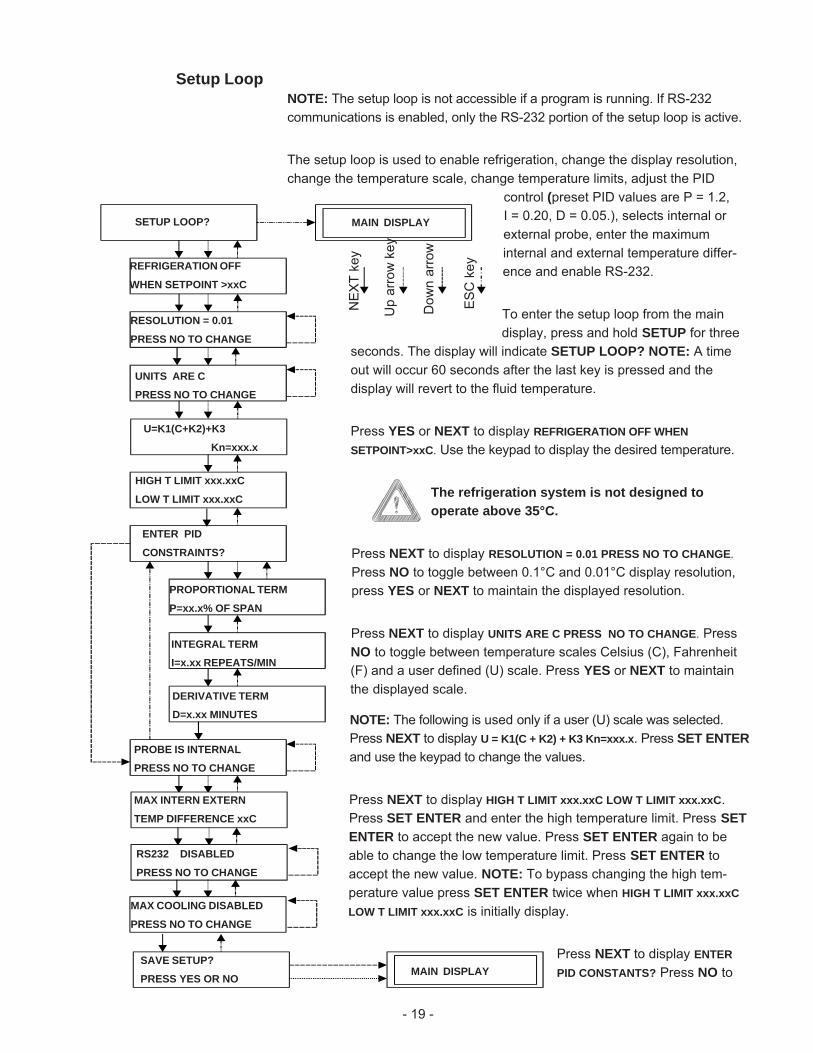
Setup LoopNOTE: The setup loop is not accessible if a program is running. If RS-232communications is enabled, only the RS-232 portion of the setup loop is active.
The setup loop is used to enable refrigeration, change the display resolution,change the temperature scale, change temperature limits, adjust the PID
control (preset PID values are P = 1.2,I = 0.20, D = 0.05.), selects internal orexternal probe, enter the maximuminternal and external temperature differ-ence and enable RS-232.
To enter the setup loop from the maindisplay, press and hold SETUP for three
seconds. The display will indicate SETUP LOOP? NOTE: A timeout will occur 60 seconds after the last key is pressed and thedisplay will revert to the fluid temperature.
Press YES or NEXT to display REFRIGERATION OFF WHENSETPOINT>xxC. Use the keypad to display the desired temperature.
The refrigeration system is not designed tooperate above 35°C.
Press NEXT to display RESOLUTION = 0.01 PRESS NO TO CHANGE.Press NO to toggle between 0.1°C and 0.01°C display resolution,press YES or NEXT to maintain the displayed resolution.
Press NEXT to display UNITS ARE C PRESS NO TO CHANGE. PressNO to toggle between temperature scales Celsius (C), Fahrenheit(F) and a user defined (U) scale. Press YES or NEXT to maintainthe displayed scale.
NOTE: The following is used only if a user (U) scale was selected.Press NEXT to display U = K1(C + K2) + K3 Kn=xxx.x. Press SET ENTERand use the keypad to change the values.
Press NEXT to display HIGH T LIMIT xxx.xxC LOW T LIMIT xxx.xxC.Press SET ENTER and enter the high temperature limit. Press SETENTER to accept the new value. Press SET ENTER again to beable to change the low temperature limit. Press SET ENTER toaccept the new value. NOTE: To bypass changing the high tem-perature value press SET ENTER twice when HIGH T LIMIT xxx.xxCLOW T LIMIT xxx.xxC is initially display.
Press NEXT to display ENTERPID CONSTANTS? Press NO to
SETUP LOOP?
DERIVATIVE TERM
D=x.xx MINUTES
INTEGRAL TERM
I=x.xx REPEATS/MIN
ENTER PID
CONSTRAINTS?
U=K1(C+K2)+K3
Kn=xxx.x
REFRIGERATION OFF
WHEN SETPOINT >xxC
RESOLUTION = 0.01
PRESS NO TO CHANGE
HIGH T LIMIT xxx.xxC
LOW T LIMIT xxx.xxC
UNITS ARE C
PRESS NO TO CHANGE
PROPORTIONAL TERM
P=xx.x% OF SPAN
SAVE SETUP?
PRESS YES OR NO
PROBE IS INTERNAL
PRESS NO TO CHANGE
MAX INTERN EXTERN
TEMP DIFFERENCE xxC
RS232 DISABLED
PRESS NO TO CHANGE
MAX COOLING DISABLED
PRESS NO TO CHANGE
MAIN DISPLAY
NEX
T ke
y
MAIN DISPLAY
ES
C k
ey
Up
arro
w k
ey
Dow
n ar
row
- 20 -
bypass changing the constants and display PROBE IS INTERNAL PRESS NO TOCHANGE or press NEXT to display PROPORTIONAL TERM P = xx.x% OF SPAN.Press SET ENTER and use the keypad to enter the desired value.
Press NEXT to display INTEGRAL TERM I = x.xx REPEATS/MIN. Press SETENTER and use the keypad to enter the desired value.
Press NEXT to display DERIVATIVE TERM D = x.xx MINUTES. PressSET ENTER and use the keypad to enter the desired value.
Press NEXT to display PROBE IS INTERNAL PRESS NO TO CHANGE. Press NOto toggle between internal or external probe or press YES or SET ENTER touse the displayed probe.
Press NEXT to display MAX INTERN EXTERN TEMP DIFFERENCE xxC. PressSET ENTER and use the keypad to enter the desired value.
Press NEXT to display RS232 IS DISABLED PRESS NO TO CHANGE. Press NOto toggle between disabled and enabled or press YES or SET ENTER to usethe displayed mode.
Press NEXT to display MAX COOLING DISABLED PRESS NO TO CHANGE. PressNO to toggle between disabled and enabled or press YES or SET ENTER touse the displayed mode.
Press NEXT to display SAVE SETUP? PRESS YES OR NO. Press YES to acceptthe changes. Press NO to ignore them. The unit will return to the maindisplay.
- 21 -
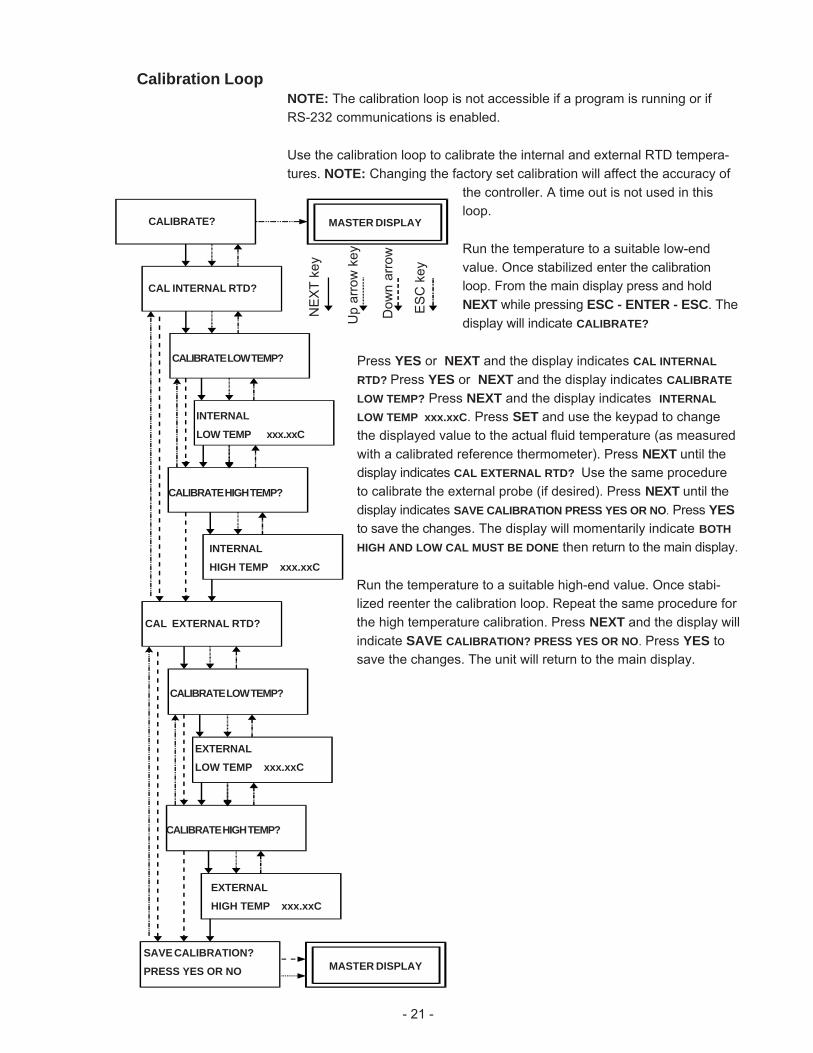
Calibration LoopNOTE: The calibration loop is not accessible if a program is running or ifRS-232 communications is enabled.
Use the calibration loop to calibrate the internal and external RTD tempera-tures. NOTE: Changing the factory set calibration will affect the accuracy of
the controller. A time out is not used in thisloop.
Run the temperature to a suitable low-endvalue. Once stabilized enter the calibrationloop. From the main display press and holdNEXT while pressing ESC - ENTER - ESC. Thedisplay will indicate CALIBRATE?
Press YES or NEXT and the display indicates CAL INTERNALRTD? Press YES or NEXT and the display indicates CALIBRATELOW TEMP? Press NEXT and the display indicates INTERNALLOW TEMP xxx.xxC. Press SET and use the keypad to changethe displayed value to the actual fluid temperature (as measuredwith a calibrated reference thermometer). Press NEXT until thedisplay indicates CAL EXTERNAL RTD? Use the same procedureto calibrate the external probe (if desired). Press NEXT until thedisplay indicates SAVE CALIBRATION PRESS YES OR NO. Press YESto save the changes. The display will momentarily indicate BOTHHIGH AND LOW CAL MUST BE DONE then return to the main display.
Run the temperature to a suitable high-end value. Once stabi-lized reenter the calibration loop. Repeat the same procedure forthe high temperature calibration. Press NEXT and the display willindicate SAVE CALIBRATION? PRESS YES OR NO. Press YES tosave the changes. The unit will return to the main display.
CALIBRATE? MASTER DISPLAY
NEX
T ke
y
ES
C k
ey
CAL INTERNAL RTD?
CALIBRATE LOW TEMP?
INTERNAL
LOW TEMP xxx.xxC
CALIBRATE HIGH TEMP?
INTERNAL
HIGH TEMP xxx.xxC
CAL EXTERNAL RTD?
CALIBRATE LOW TEMP?
EXTERNAL
LOW TEMP xxx.xxC
CALIBRATE HIGH TEMP?
EXTERNAL
HIGH TEMP xxx.xxC
MASTER DISPLAYSAVE CALIBRATION?
PRESS YES OR NO
Up
arro
w k
ey
Dow
n ar
row
- 22 -
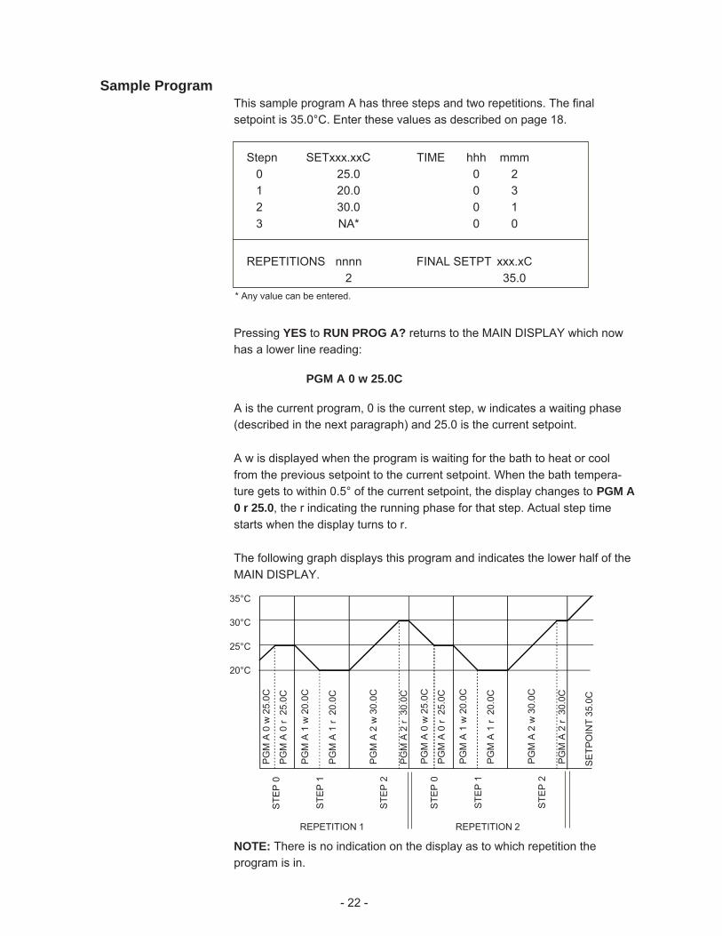
Sample ProgramThis sample program A has three steps and two repetitions. The finalsetpoint is 35.0°C. Enter these values as described on page 18.
Stepn SETxxx.xxC TIME hhh mmm0 25.0 0 21 20.0 0 32 30.0 0 13 NA* 0 0
REPETITIONS nnnn FINAL SETPT xxx.xC2 35.0
Pressing YES to RUN PROG A? returns to the MAIN DISPLAY which nowhas a lower line reading:
PGM A 0 w 25.0C
A is the current program, 0 is the current step, w indicates a waiting phase(described in the next paragraph) and 25.0 is the current setpoint.
A w is displayed when the program is waiting for the bath to heat or coolfrom the previous setpoint to the current setpoint. When the bath tempera-ture gets to within 0.5° of the current setpoint, the display changes to PGM A0 r 25.0, the r indicating the running phase for that step. Actual step timestarts when the display turns to r.
The following graph displays this program and indicates the lower half of theMAIN DISPLAY.
* Any value can be entered.
NOTE: There is no indication on the display as to which repetition theprogram is in.
35°C
30°C
25°C
20°C
PGM
A 1
w 2
0.0C
PGM
A 0
w 2
5.0C
PGM
A 2
w 3
0.0C
PG
M A
0 r
25.
0C
PG
M A
1 r
20.
0C
PG
M A
2 r
30.
0C
PGM
A 1
w 2
0.0C
PGM
A 0
w 2
5.0C
PGM
A 2
w 3
0.0C
PG
M A
0 r
25.
0C
PG
M A
1 r
20.
0C
PG
M A
2 r
30.
0C
SE
TPO
INT
35.0
C
STE
P 0
STE
P 1
STE
P 2
STE
P 0
STE
P 1
STE
P 2
REPETITION 1 REPETITION 2
- 23 -
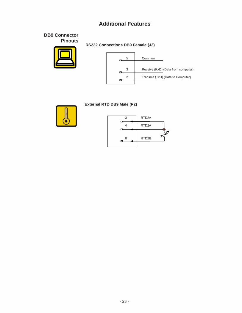
DB9 ConnectorPinouts
RS232 Connections DB9 Female (J3)
5 Common
3 Receive (RxD) (Data from computer)
2 Transmit (TxD) (Data to Computer)
External RTD DB9 Male (P2)
3 RTD2A
4 RTD2A
8 RTD2B
Additional Features
- 24 -
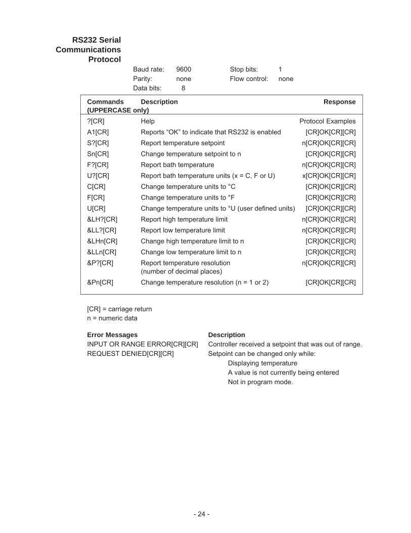
RS232 SerialCommunications
ProtocolBaud rate: 9600 Stop bits: 1Parity: none Flow control: noneData bits: 8
Commands Description Response(UPPERCASE only)?[CR] Help Protocol ExamplesA1[CR] Reports “OK” to indicate that RS232 is enabled [CR]OK[CR][CR]S?[CR] Report temperature setpoint n[CR]OK[CR][CR]Sn[CR] Change temperature setpoint to n [CR]OK[CR][CR]F?[CR] Report bath temperature n[CR]OK[CR][CR]U?[CR] Report bath temperature units (x = C, F or U) x[CR]OK[CR][CR]C[CR] Change temperature units to °C [CR]OK[CR][CR]F[CR] Change temperature units to °F [CR]OK[CR][CR]U[CR] Change temperature units to °U (user defined units) [CR]OK[CR][CR]&LH?[CR] Report high temperature limit n[CR]OK[CR][CR]&LL?[CR] Report low temperature limit n[CR]OK[CR][CR]&LHn[CR] Change high temperature limit to n [CR]OK[CR][CR]&LLn[CR] Change low temperature limit to n [CR]OK[CR][CR]&P?[CR] Report temperature resolution n[CR]OK[CR][CR]
(number of decimal places)&Pn[CR] Change temperature resolution (n = 1 or 2) [CR]OK[CR][CR]
[CR] = carriage returnn = numeric data
Error Messages DescriptionINPUT OR RANGE ERROR[CR][CR] Controller received a setpoint that was out of range.REQUEST DENIED[CR][CR] Setpoint can be changed only while:
Displaying temperatureA value is not currently being enteredNot in program mode.
- 25 -
High Temperature/Low Liquid
Level SafetyTo protect your application, the adjustable High Temperature/Low LiquidLevel Safety (HIGH TEMP/LOW LEVEL) ensures the heater will not exceedtemperatures which can cause serious damage to your unit. A single tem-perature sensor, located on the heater coils in the circulator, monitors bothconditions. A High Temperature/Low Liquid Level fault occurs when thetemperature of the sensor exceeds the set temperature limit.
In the event of a fault, the unit will shut down and a FAULT LED will illumi-nate. The cause of the fault must be identified and corrected before the unitcan be restarted.
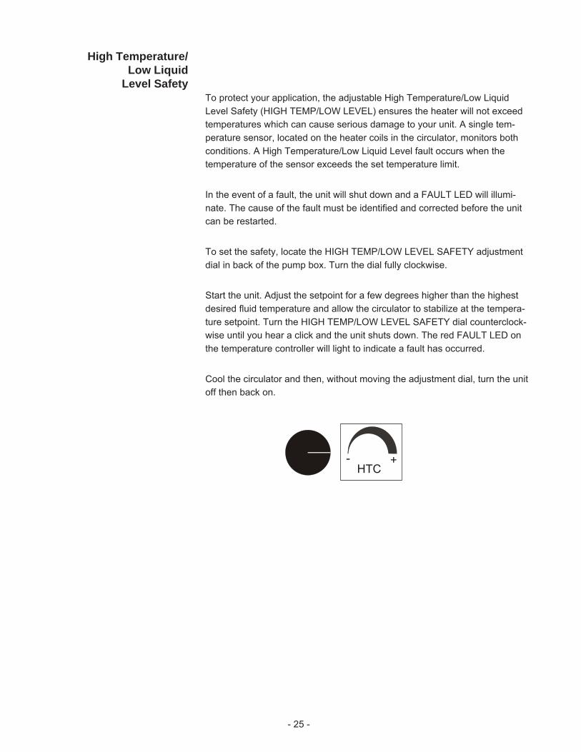
To set the safety, locate the HIGH TEMP/LOW LEVEL SAFETY adjustmentdial in back of the pump box. Turn the dial fully clockwise.
Start the unit. Adjust the setpoint for a few degrees higher than the highestdesired fluid temperature and allow the circulator to stabilize at the tempera-ture setpoint. Turn the HIGH TEMP/LOW LEVEL SAFETY dial counterclock-wise until you hear a click and the unit shuts down. The red FAULT LED onthe temperature controller will light to indicate a fault has occurred.
Cool the circulator and then, without moving the adjustment dial, turn the unitoff then back on.
HTC+-
- 26 -
Maintenance & TroubleshootingCleaning
Allow sufficient for the fluid to cool to room temperature before han-dling.
Turn the unit off before cleaning.
Routine cleaning can be achieved by simply sponging down the seamlessstainless steel tank with a mild soapy solution.
Do not use steel wool; its abrasiveness will lead to rusting.
Dry the circulator using a soft cloth.
For proper operation, the unit needs to pull substantial amounts of airthrough a condenser. A build up of dust or debris on the fins of the con-denser will lead to a loss of cooling capacity.
Periodic vacuuming of the condenser is necessary. The frequency of clean-ing depends on the operating environment. After initial installation we recom-mend the wrapper be removed and a monthly visual inspection of thecondenser be made. After several months the frequency of cleaning will beestablished.
AlgaeTo restrict the growth of algae in the circulator, we recommend the circulatorcover be kept in place and that all circulation lines be opaque. This willeliminate the entrance of light required for the growth of most common algae.
We recommend the use of Chloramine-T, 1 gram per 3.5 liters.
ChecklistUnit will not startMake sure the voltage of the power source meets the specified voltage,±10%. Refer to the serial number label on the rear of the unit to identify thespecific electrical requirements of your unit.
Check the High Temperature/Low Liquid Level Safety. If the FAULT light ison, make sure the fluid level in the circulator is between the marks in thebaffle and the HIGH TEMP/LOW LEVEL SAFETY setting is greater than thefluid temperature. Turn the unit's I/O switch off then back on to reset thesafety.
- 27 -
Loss of cooling capacityBe sure the cooling capacity of the unit has not been exceeded if circulatingto an external system.
When the unit is shut off, wait approximately five minutes before restarting.This allows time for the refrigeration pressures to equalize. If the pressuresare not allowed to equalize, the compressor will short-cycle (clicking sound)and no cooling will occur.
Proper ventilation is required for heat removal. Make sure ventilationthrough the front and rear panels is not impeded and the panels are free ofdust and debris.
Ice build up on the cooling coils can act as insulation and lower the coolingcapacity. Raise the temperature of the circulator to de-ice the cooling coiland increase the concentration of non-freezing fluid.
Check controller PID values, see below.
No external circulationMake sure the stainless steel plugs on the PUMP INLET and PUMPOUTLET have been removed.
Check for obstructions, kinks, or leaks in the circulation tubing.
Circulation will cease when the pump head has been exceeded.
PID ValuesThe PID values can be verified in the controller's Setup Loop. The factorypreset PID values are:
Digital P = 1.2 I = 0.20 D = 0.05
Advanced Digital P = 1.2 I = 0.20 D = 0.05
Programmable P = 1.2 I = 0.20 D = 0.05
- 28 -
Unfavorably high total ionized solids (TIS) can accelerate the rate of galvaniccorrosion. These contaminants can function as electrolytes which increasethe potential for galvanic cell corrosion and lead to localized corrosion suchas pitting which can be observed at the studs and on the outside surface ofcooling coils. Eventually, the pitting will become so extensive that the coil willleak refrigerant into the water reservoir.
For example, tap water in the U.S. averages 171 ppm (of NaCl). The recom-mended level for use in a water system is between 0.5 to 5.0 ppm (of NaCl).
Recommendation: Initially fill the tank with distilled/deionized water. Do notuse untreated tap water as the total ionized solids level may be too high.
Maintain this water quality at a resistivity of between 1 to 10 MOhmcm(compensated to 25°C) by using a purification system. Although the initial fillmay be as high as 18 MOhmcm (compensated to 25°C), the desired level forlong time usage is 1 to 3 MOhmcm (compensated to 25°C).
The above two recommendations will reduce the electrolytic potential of thewater and prevent or reduce the galvanic corrosion observed.
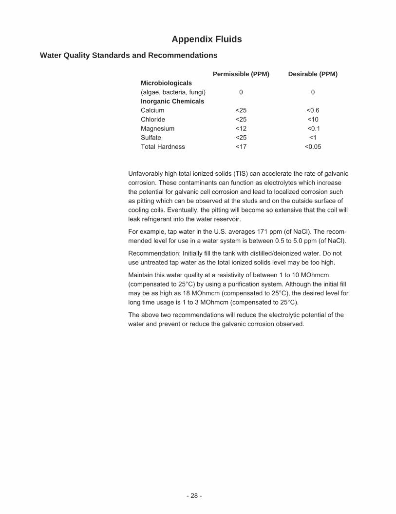
Appendix Fluids Water Quality Standards and Recommendations
Permissible (PPM) Desirable (PPM)Microbiologicals(algae, bacteria, fungi) 0 0Inorganic ChemicalsCalcium <25 <0.6Chloride <25 <10Magnesium <12 <0.1Sulfate <25 <1Total Hardness <17 <0.05