Embed Size (px)
Citation preview
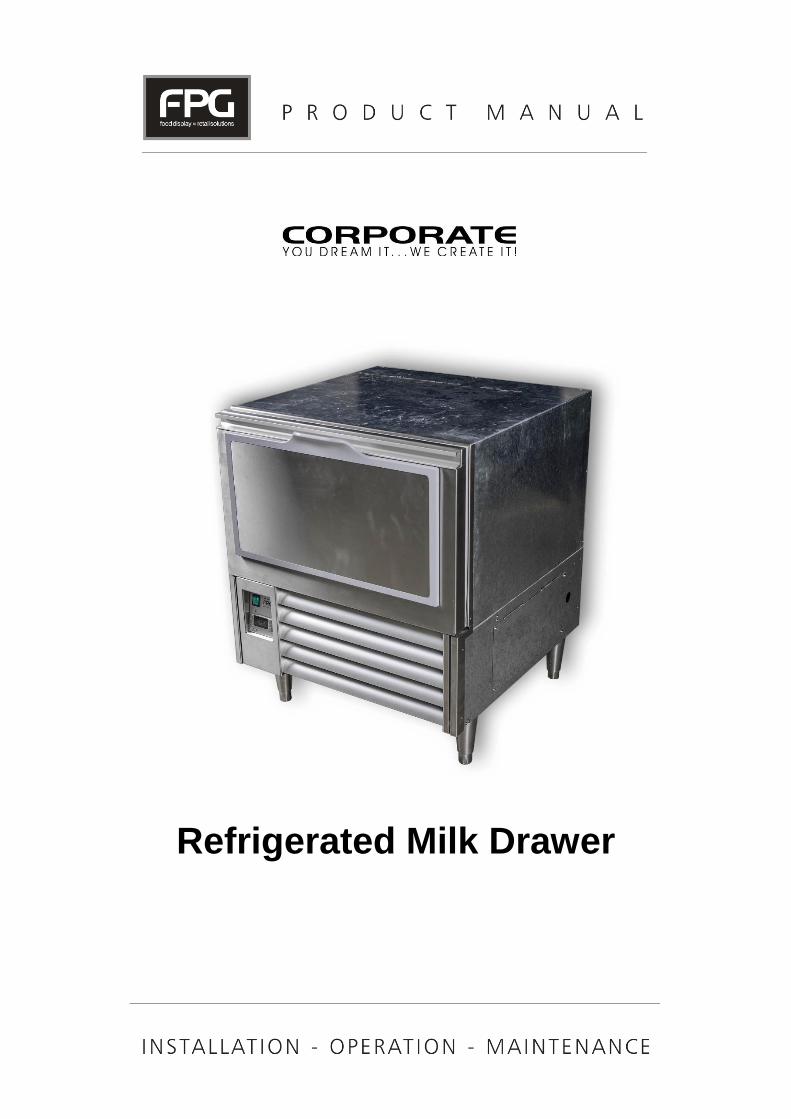
Refrigerated Milk Drawer
Part No. 26984 Rev. C May 2018 - 2 - Refrigerated Milk Drawer
Copyright © May 2018 Future Products Group Limited. All rights reserved.
No part of this publication may be reproduced, stored in a retrieval system, or transmitted in any form or by any means, electronic, mechanical, photocopying, recording or otherwise, without the prior written permission of Future Products Group Ltd.
IL-C-DRW-A001/A003 - 3 - © Future Products Group
Table of Contents
INTRODUCTION ................................................................................................................ 6
Welcome .......................................................................................................................................................... 6
Future Products Group (FPG) ................................................................................................................... 6 Guidance and Help .................................................................................................................................... 6
Warranty .......................................................................................................................................................... 6
Warranty Period ........................................................................................................................................ 6 Liability Exceptions .................................................................................................................................... 7 Specific Exclusions .................................................................................................................................... 7 Assessment ............................................................................................................................................... 7 Time Limit .................................................................................................................................................. 7 Caution ...................................................................................................................................................... 7
OPERATION ...................................................................................................................... 8
Cabinet Features ............................................................................................................................................ 8
Large Capacity .......................................................................................................................................... 8 Adjustable Guides ..................................................................................................................................... 8 Access Flap ............................................................................................................................................... 8 Control Panels ........................................................................................................................................... 9 Temperature Controller ............................................................................................................................. 9
Preparation ..................................................................................................................................................... 9
Load the Drawer ........................................................................................................................................ 9 Power Supply .......................................................................................................................................... 10 Close the Drawer ..................................................................................................................................... 10 Turn on Main Switch ................................................................................................................................ 10
Operating Routines ...................................................................................................................................... 10
After Hours .............................................................................................................................................. 10 Cleaning .................................................................................................................................................. 10 De-frost Cycle.......................................................................................................................................... 10
TROUBLE SHOOTING .................................................................................................... 11
Fault Alarm Procedure ................................................................................................................................. 12
Dixell CA Fault......................................................................................................................................... 12
CLEANING ...................................................................................................................... 13
Cautions ........................................................................................................................................................ 13
Power ...................................................................................................................................................... 13 Water ....................................................................................................................................................... 13
Exterior .......................................................................................................................................................... 13
Plastic and Metal Surfaces ...................................................................................................................... 13 Drawer Runners ...................................................................................................................................... 13 Louvers ................................................................................................................................................... 13 Pre-filter ................................................................................................................................................... 13
Part No. 26984 Rev. C May 2018 - 4 - Refrigerated Milk Drawer
Interior ........................................................................................................................................................... 14
Empty the Drawer .................................................................................................................................... 14 Lift Out Plastic Guides ............................................................................................................................. 14 Lift Out Sloping Base Tray ...................................................................................................................... 14 Lift Out the Baffle Plate ........................................................................................................................... 14
Cleaning Routines ........................................................................................................................................ 15
Schedules................................................................................................................................................ 15 Removable Filter ..................................................................................................................................... 15 Condenser Radiator ................................................................................................................................ 15 Inspection ................................................................................................................................................ 15 Correction ................................................................................................................................................ 15
INSTALLATION ............................................................................................................... 16
Regulations ................................................................................................................................................... 16
Compliance with Local Requirements ..................................................................................................... 16
Setting Up ..................................................................................................................................................... 16
Unpacking ............................................................................................................................................... 16 Positioning the Cabinet ........................................................................................................................... 16 Support Bolt............................................................................................................................................. 16 Condensate Drain ................................................................................................................................... 17 Cabinet Preparation ................................................................................................................................ 17 Power Supply and Earthing ..................................................................................................................... 17 Connection Terminals ............................................................................................................................. 17 Isolation ................................................................................................................................................... 17
Mains Lead .................................................................................................................................................... 17
Lead Replacement .................................................................................................................................. 17
SERVICING ..................................................................................................................... 18
Control Gear ................................................................................................................................................. 18
Control Gear Location ............................................................................................................................. 18 Control Gear Chassis .............................................................................................................................. 18 Heating Element ...................................................................................................................................... 18 Drawer Catch Adjustment ....................................................................................................................... 18
Refrigeration ................................................................................................................................................. 19
Caution .................................................................................................................................................... 19 Removable Filters ................................................................................................................................... 19 Condenser Radiator ................................................................................................................................ 19 Access to Refrigeration Equipment ......................................................................................................... 19 Support Bolt............................................................................................................................................. 20 Evaporator Access .................................................................................................................................. 20 Evaporator Fans ...................................................................................................................................... 20 Temperature Probes ............................................................................................................................... 20
IL-C-DRW-A001/A003 - 5 - © Future Products Group
Temperature Regulator XR40CX ............................................................................................................ 21 XR40CX Key Functions ........................................................................................................................... 22 XR40CX LED Functions .......................................................................................................................... 22 XR40CX Display the Set-point ................................................................................................................ 23 XR40CX Start a Manual Defrost............................................................................................................. 23 FPG Settings ........................................................................................................................................... 25 Dixell Default Settings ............................................................................................................................. 25 XR40CX Hot Key .................................................................................................................................... 26 XR40CX Alarm Signals ........................................................................................................................... 27 XR40CX Alarm Recovery ........................................................................................................................ 27 XR40CX Connections ............................................................................................................................. 27
SPECIFICATIONS ........................................................................................................... 28
Mechanical .................................................................................................................................................... 28
Electrical ....................................................................................................................................................... 28
Controller Settings ....................................................................................................................................... 29
Changes from Dixell Defaults .................................................................................................................. 29 1. XR40CX Settings ............................................................................................................................. 29 NOTE ...................................................................................................................................................... 29
Compliance ................................................................................................................................................... 30
Safety Aspects ........................................................................................................................................ 30 Operational Safety ................................................................................................................................... 30 Refrigeration Performance ...................................................................................................................... 30
Improvements ............................................................................................................................................... 30
On-going Development ........................................................................................................................... 30
ELECTRICAL CIRCUIT DIAGRAMS ............................................................................... 31
Model: IL-C-DRW-A001/A003 ................................................................................................................. 31
SPARE PARTS ................................................................................................................ 32
Cabinet Serial Number ............................................................................................................................ 32
MECHANICAL DRAWINGS ............................................................................................. 33
Model: IL-C-DRW-A001 .......................................................................................................................... 33 Model: IL-C-DRW-A003 .......................................................................................................................... 34
Part No. 26984 Rev. C May 2018 - 6 - Refrigerated Milk Drawer
INTRODUCTION Welcome REFRIGERATED CABINETS - INTRODUCTION
Future Products Group (FPG)
Welcome to the world of FPG! Our products are designed and engineered to give you the optimal performance that you deserve with innovative visual merchandising appeal. We are confident that you will be delighted with your state of the art inline food service cabinet, and that it will become a valued appliance in your store.
Guidance and Help
Any new appliance can seem very complex and confusing at first glance. To ensure you receive the utmost benefit from your new inline cabinet, there are two things you can do.
• Before operating the cabinet, please read the instruction book carefully and follow its recommendations. The time taken will be well spent. These instructions both general and technical tell you how to operate and look after your inline food service cabinet so that you can receive the full benefits that this cabinet has to offer.
• These instructions cannot, however, cover all eventualities. If you are unsure of any aspect of the installation, instructions or performance of your cabinet, contact your dealer promptly or contact us via email to [email protected].
Warranty REFRIGERATED CABINETS - INTRODUCTION
Warranty Period
Future Products Group Limited warrants, to the original purchaser of an FPG manufactured food service cabinet that for ONE YEAR (12 months), from the date of purchase, any defect in workmanship or material resulting in the product malfunctioning while under correct use will be rectified.
The warranty is extended to THREE YEARS (36 months), for refrigeration condenser units. Conditions apply, see Liability Exceptions.
Liability under this warranty is limited to replacing or repairing a part, without charge.
Continued on next page
IL-C-DRW-A001/A003 - 7 - © Future Products Group
Warranty cont. REFRIGERATED CABINETS - INTRODUCTION
Liability Exceptions
Liability under this warranty does not include:
• Any loss, or damage or expenses directly or indirectly arising from use or inability to use the product or from any other cause.
• Any part of the cabinet which has been subject to misuse, neglect, alteration, incorrect installation, accident, or damage caused by transportation, use of abrasive or caustic chemicals, flooding, fire or acts of God.
• Damage, resulting from failure to have the cabinet regularly serviced every three months by a refrigeration engineer. NB: You will be required to provide copies of service records in the event of compressor failure.
• Any damage or malfunction resulting from the use of non-FPG supplied spare parts.
Specific Exclusions
The following are specifically excluded from warranty:
• Breakage of glass or plastic components or the replacement of gaskets.
• Maladjustment of the electronic refrigeration controller, by an unqualified person.
• Failure resulting from a lack of routine compressor / radiator cleaning.
• Failure to re-assemble the cabinet correctly after cleaning.
• Fair wear and tear.
Assessment The liability under this warranty is dependent on an assessment by FPG, to determine the defect in workmanship or materials.
Time Limit FPG does not guarantee that any service to be performed under this warranty
will be carried out within any particular time limit.
Caution No warranty claim will be accepted unless authorised by FPG prior to
commencement of service.
Part No. 26984 Rev. C May 2018 - 8 - Refrigerated Milk Drawer
OPERATION
Cabinet Features REFRIGERATED CABINETS - OPERATION
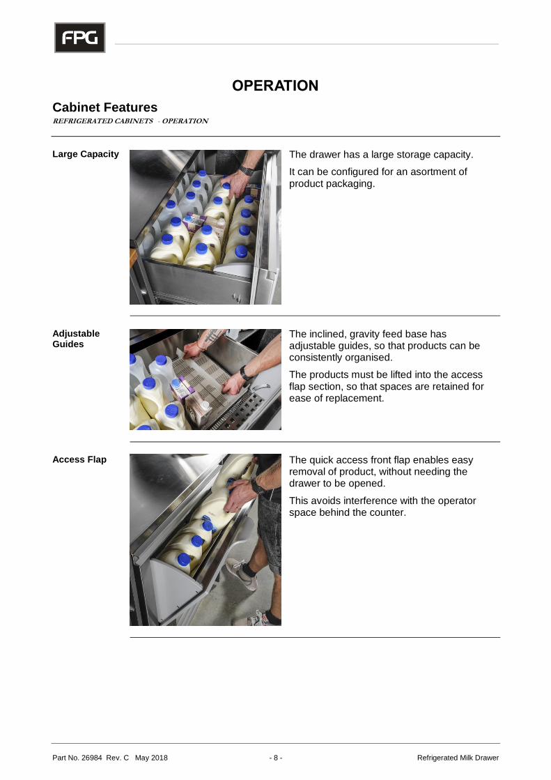
Large Capacity The drawer has a large storage capacity.
It can be configured for an asortment of product packaging.
Adjustable Guides
The inclined, gravity feed base has adjustable guides, so that products can be consistently organised.
The products must be lifted into the access flap section, so that spaces are retained for ease of replacement.
Access Flap The quick access front flap enables easy
removal of product, without needing the drawer to be opened.
This avoids interference with the operator space behind the counter.
IL-C-DRW-A001/A003 - 9 - © Future Products Group
Controls REFRIGERATED CABINETS - OPERATION
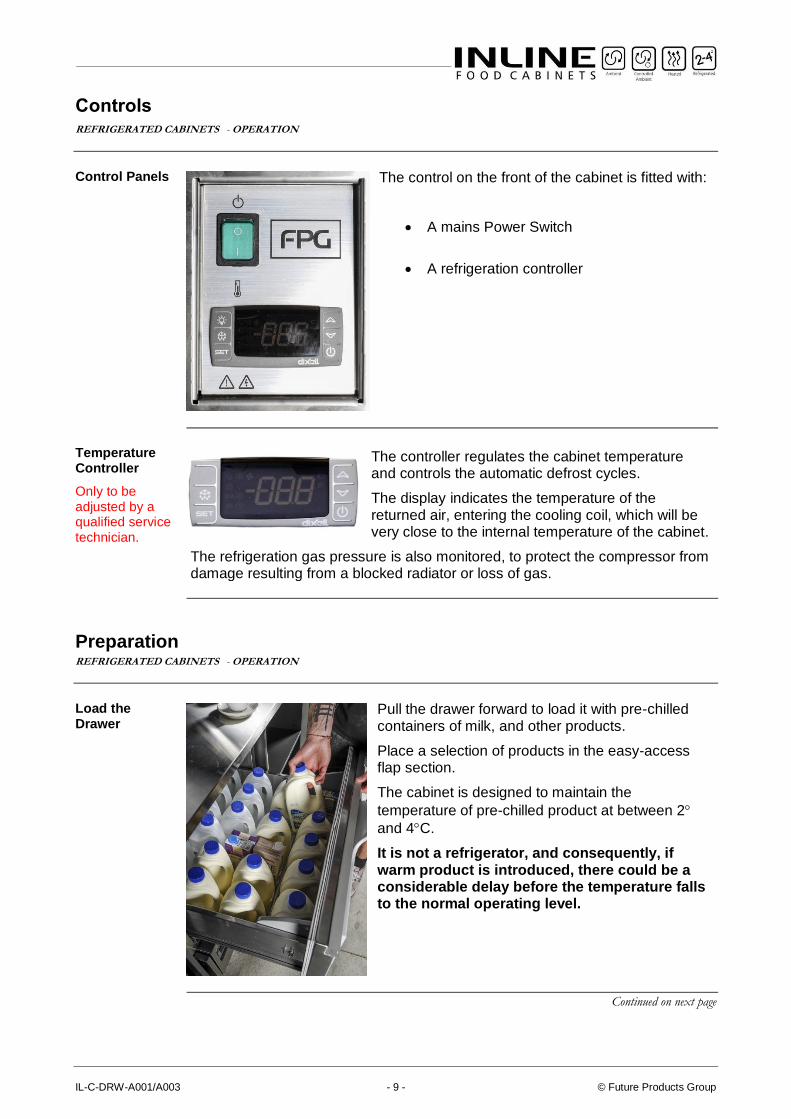
Control Panels The control on the front of the cabinet is fitted with:
• A mains Power Switch
• A refrigeration controller
Temperature Controller
Only to be adjusted by a qualified service technician.
The controller regulates the cabinet temperature and controls the automatic defrost cycles.
The display indicates the temperature of the returned air, entering the cooling coil, which will be very close to the internal temperature of the cabinet.
The refrigeration gas pressure is also monitored, to protect the compressor from damage resulting from a blocked radiator or loss of gas.
Preparation REFRIGERATED CABINETS - OPERATION
Load the Drawer
Pull the drawer forward to load it with pre-chilled containers of milk, and other products.
Place a selection of products in the easy-access flap section.
The cabinet is designed to maintain the
temperature of pre-chilled product at between 2
and 4C.
It is not a refrigerator, and consequently, if warm product is introduced, there could be a considerable delay before the temperature falls to the normal operating level.
Continued on next page
Part No. 26984 Rev. C May 2018 - 10 - Refrigerated Milk Drawer
Preparation cont.
REFRIGERATED CABINETS - OPERATION
Power Supply Ensure that power is connected to the cabinet.
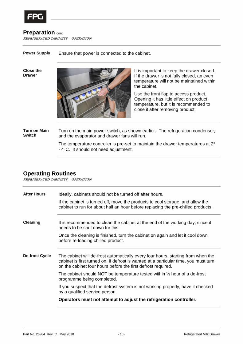
Close the Drawer
It is important to keep the drawer closed. If the drawer is not fully closed, an even temperature will not be maintained within the cabinet.
Use the front flap to access product. Opening it has little effect on product temperature, but it is recommended to close it after removing product.
Turn on Main Switch
Turn on the main power switch, as shown earlier. The refrigeration condenser, and the evaporator and drawer fans will run.
The temperature controller is pre-set to maintain the drawer temperatures at 2
- 4C. It should not need adjustment.
Operating Routines REFRIGERATED CABINETS - OPERATION
After Hours Ideally, cabinets should not be turned off after hours.
If the cabinet is turned off, move the products to cool storage, and allow the cabinet to run for about half an hour before replacing the pre-chilled products.
Cleaning It is recommended to clean the cabinet at the end of the working day, since it
needs to be shut down for this.
Once the cleaning is finished, turn the cabinet on again and let it cool down before re-loading chilled product.
De-frost Cycle The cabinet will de-frost automatically every four hours, starting from when the cabinet is first turned on. If defrost is wanted at a particular time, you must turn on the cabinet four hours before the first defrost required.
The cabinet should NOT be temperature tested within ½ hour of a de-frost programme being completed.
If you suspect that the defrost system is not working properly, have it checked by a qualified service person.
Operators must not attempt to adjust the refrigeration controller.
IL-C-DRW-A001/A003 - 11 - © Future Products Group
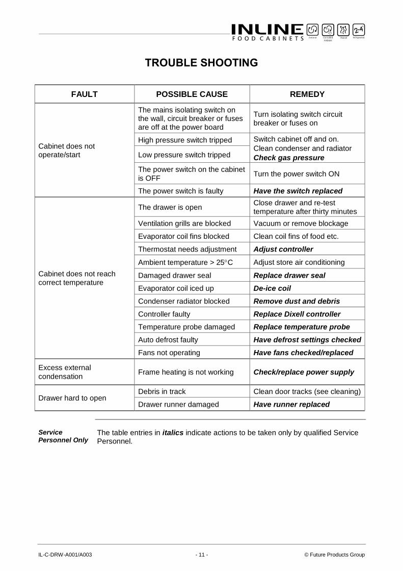
TROUBLE SHOOTING
FAULT POSSIBLE CAUSE REMEDY
Cabinet does not operate/start
The mains isolating switch on the wall, circuit breaker or fuses are off at the power board
Turn isolating switch circuit breaker or fuses on
High pressure switch tripped Switch cabinet off and on.
Clean condenser and radiator
Check gas pressure Low pressure switch tripped
The power switch on the cabinet
is OFF Turn the power switch ON
The power switch is faulty Have the switch replaced
Cabinet does not reach correct temperature
The drawer is open Close drawer and re-test temperature after thirty minutes
Ventilation grills are blocked Vacuum or remove blockage
Evaporator coil fins blocked Clean coil fins of food etc.
Thermostat needs adjustment Adjust controller
Ambient temperature > 25C Adjust store air conditioning
Damaged drawer seal Replace drawer seal
Evaporator coil iced up De-ice coil
Condenser radiator blocked Remove dust and debris
Controller faulty Replace Dixell controller
Temperature probe damaged Replace temperature probe
Auto defrost faulty Have defrost settings checked
Fans not operating Have fans checked/replaced
Excess external
condensation Frame heating is not working Check/replace power supply
Drawer hard to open Debris in track Clean door tracks (see cleaning)
Drawer runner damaged Have runner replaced
Service Personnel Only
The table entries in italics indicate actions to be taken only by qualified Service Personnel.
Part No. 26984 Rev. C May 2018 - 12 - Refrigerated Milk Drawer
Fault Alarm Procedure REFRIGERATED CABINETS - TROUBLE SHOOTING
Dixell CA Fault
If a “CA” fault alarm appears on the Dixell controller screen, take the following action:
1. Turn off the power supply to the cabinet
2. Clean the condenser pre-filter or the condenser coil if the cabinet is not equipped with a pre-filter
3. Turn on the power supply to the cabinet
4. If the cabinet does not cool, or if the “CA” fault alarm returns within 24Hrs, call for service.
IL-C-DRW-A001/A003 - 13 - © Future Products Group
CLEANING
Cautions REFRIGERATED CABINETS - CLEANING
Power ALWAYS TURN THE POWER SUPPLY OFF BEFORE CLEANING.
Water THIS UNIT IS NOT WATERPROOF. DO NOT USE A WATER JET SPRAY TO
CLEAN THE INTERIOR OR EXTERIOR OF THIS CABINET.
Exterior REFRIGERATED CABINETS - CLEANING
Plastic and Metal Surfaces
Plastic or stainless steel surfaces should be cleaned with hot soapy water or a good quality glass cleaner.
DO NOT clean surfaces with abrasive pads or cleaners as surfaces will be damaged.
Drawer Runners
With the drawer fully open, vacuum or brush away any debris in the runners, located on each side.
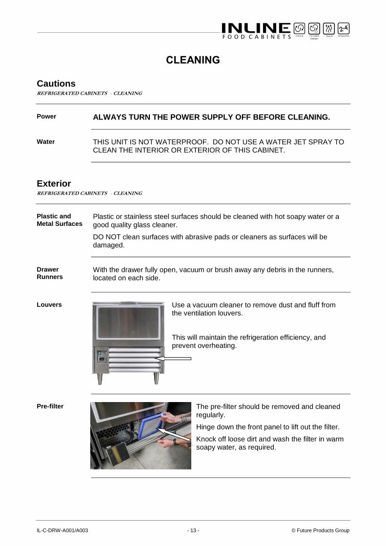
Louvers Use a vacuum cleaner to remove dust and fluff from
the ventilation louvers.
This will maintain the refrigeration efficiency, and prevent overheating.
Pre-filter The pre-filter should be removed and cleaned
regularly.
Hinge down the front panel to lift out the filter.
Knock off loose dirt and wash the filter in warm soapy water, as required.
Part No. 26984 Rev. C May 2018 - 14 - Refrigerated Milk Drawer
Interior REFRIGERATED CABINETS - CLEANING
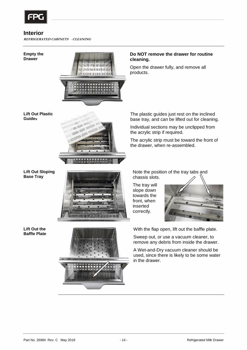
Empty the Drawer
Do NOT remove the drawer for routine cleaning.
Open the drawer fully, and remove all products.
Lift Out Plastic Guides
The plastic guides just rest on the inclined base tray, and can be lifted out for cleaning.
Individual sections may be unclipped from the acrylic strip if required.
The acrylic strip must be toward the front of the drawer, when re-assembled.
Lift Out Sloping Base Tray
Note the position of the tray tabs and chassis slots.
The tray will slope down towards the front, when inserted correctly.
Lift Out the Baffle Plate
With the flap open, lift out the baffle plate.
Sweep out, or use a vacuum cleaner, to remove any debris from inside the drawer.
A Wet-and-Dry vacuum cleaner should be used, since there is likely to be some water in the drawer.
IL-C-DRW-A001/A003 - 15 - © Future Products Group
Cleaning Routines REFRIGERATED CABINETS - CLEANING
Schedules Regular cleaning schedules are required to maintain optimum performance.
Failure to carry out routine cleaning/servicing schedules will void the warranty on the refrigeration equipment.
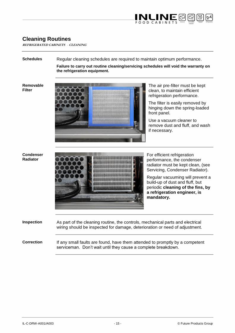
Removable Filter
The air pre-filter must be kept clean, to maintain efficient refrigeration performance.
The filter is easily removed by hinging down the spring-loaded front panel.
Use a vacuum cleaner to remove dust and fluff, and wash if necessary.
Condenser Radiator
For efficient refrigeration performance, the condenser radiator must be kept clean, (see Servicing, Condenser Radiator).
Regular vacuuming will prevent a build-up of dust and fluff, but periodic cleaning of the fins, by a refrigeration engineer, is mandatory.
Inspection As part of the cleaning routine, the controls, mechanical parts and electrical
wiring should be inspected for damage, deterioration or need of adjustment.
Correction If any small faults are found, have them attended to promptly by a competent
serviceman. Don’t wait until they cause a complete breakdown.
Part No. 26984 Rev. C May 2018 - 16 - Refrigerated Milk Drawer
INSTALLATION
Regulations REFRIGERATED CABINETS - INSTALLATION
Compliance with Local Requirements
It is very important that your cabinet is installed correctly and that the operation is correct before use. Installation must comply with local electrical, health & safety and hygiene requirements.
Setting Up REFRIGERATED CABINETS - INSTALLATION
Unpacking Unpack and check unit for damage and report any damage to the carrier and
supplier. Report any deficiencies to your supplier.
The cabinet is supplied fully assembled.
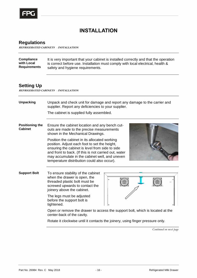
Positioning the Cabinet
Ensure the cabinet location and any bench cut- outs are made to the precise measurements shown in the Mechanical Drawings.
Position the cabinet in its allocated working position. Adjust each foot to set the height, ensuring the cabinet is level from side to side and front to back. (If this is not carried out, water may accumulate in the cabinet well, and uneven temperature distribution could also occur).
Support Bolt To ensure stability of the cabinet when the drawer is open, the threaded plastic bolt must be screwed upwards to contact the joinery above the cabinet.
The legs must be adjusted before the support bolt is tightened.
Open or remove the drawer to access the support bolt, which is located at the center-back of the cavity.
Rotate it clockwise until it contacts the joinery, using finger pressure only.
Continued on next page
IL-C-DRW-A001/A003 - 17 - © Future Products Group
Setting Up cont. REFRIGERATED CABINETS - INSTALLATION
Condensate Drain
The condensate drain outlet must be connected to a suitable drain. Exit holes are provided underneath, and on either side of the cabinet.
A P-trap must be included in the piping, to prevent contaminated air from entering the cabinet.
Cabinet Preparation
Remove all tapes, ties and packers, used to prevent movement during transit.
Power Supply and Earthing
The cabinet is supplied with a mains cable and three-pin plug. If the cabinet is to be hard wired, this must only be done by a suitably qualified person.
Before connecting to the power supply, check that the local supply is correct to that shown on the rating plate, located on the rear of the cabinet.
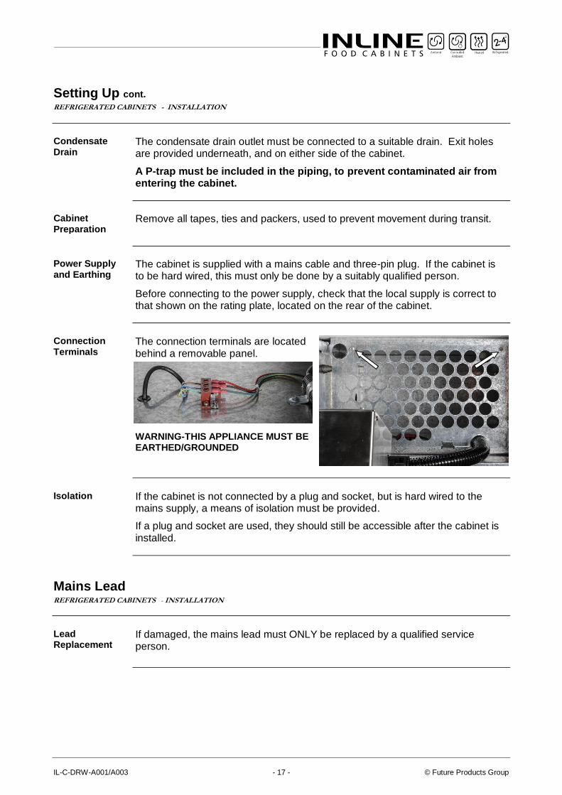
Connection Terminals
The connection terminals are located behind a removable panel.
WARNING-THIS APPLIANCE MUST BE EARTHED/GROUNDED
Isolation If the cabinet is not connected by a plug and socket, but is hard wired to the
mains supply, a means of isolation must be provided.
If a plug and socket are used, they should still be accessible after the cabinet is installed.
Mains Lead REFRIGERATED CABINETS - INSTALLATION
Lead Replacement
If damaged, the mains lead must ONLY be replaced by a qualified service person.
Part No. 26984 Rev. C May 2018 - 18 - Refrigerated Milk Drawer
SERVICING
Control Gear REFRIGERATED CABINETS - SERVICING
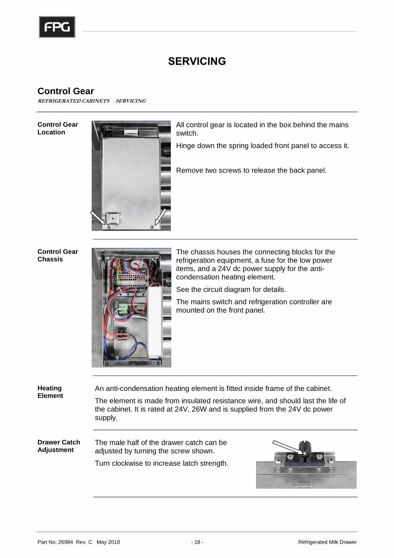
Control Gear Location
All control gear is located in the box behind the mains switch.
Hinge down the spring loaded front panel to access it.
Remove two screws to release the back panel.
Control Gear Chassis
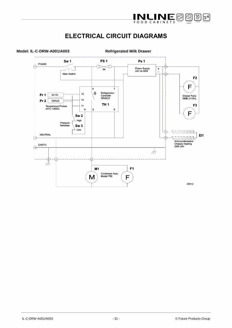
The chassis houses the connecting blocks for the refrigeration equipment, a fuse for the low power items, and a 24V dc power supply for the anti-condensation heating element.
See the circuit diagram for details.
The mains switch and refrigeration controller are mounted on the front panel.
Heating Element
An anti-condensation heating element is fitted inside frame of the cabinet.
The element is made from insulated resistance wire, and should last the life of the cabinet. It is rated at 24V, 26W and is supplied from the 24V dc power supply.
Drawer Catch Adjustment
The male half of the drawer catch can be adjusted by turning the screw shown.
Turn clockwise to increase latch strength.
IL-C-DRW-A001/A003 - 19 - © Future Products Group
Refrigeration REFRIGERATED CABINETS - SERVICING
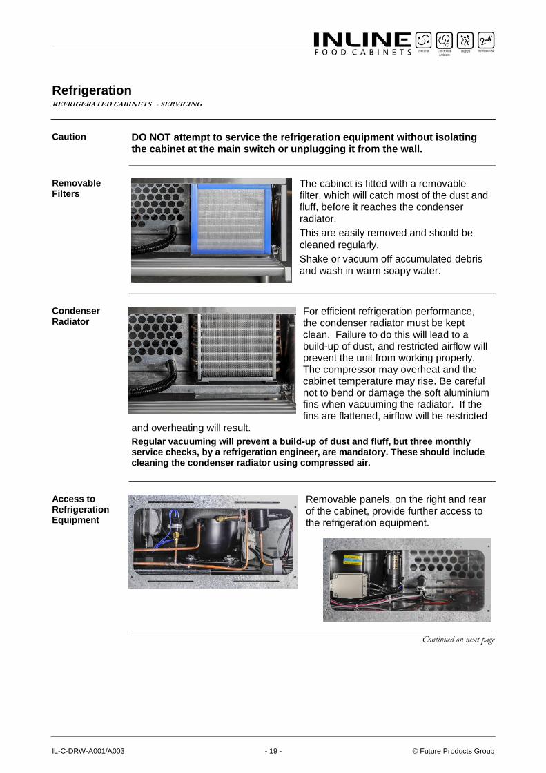
Caution DO NOT attempt to service the refrigeration equipment without isolating the cabinet at the main switch or unplugging it from the wall.
Removable Filters
The cabinet is fitted with a removable filter, which will catch most of the dust and fluff, before it reaches the condenser radiator.
This are easily removed and should be
cleaned regularly.
Shake or vacuum off accumulated debris and wash in warm soapy water.
Condenser Radiator
For efficient refrigeration performance, the condenser radiator must be kept clean. Failure to do this will lead to a build-up of dust, and restricted airflow will prevent the unit from working properly. The compressor may overheat and the cabinet temperature may rise. Be careful not to bend or damage the soft aluminium fins when vacuuming the radiator. If the fins are flattened, airflow will be restricted
and overheating will result.
Regular vacuuming will prevent a build-up of dust and fluff, but three monthly service checks, by a refrigeration engineer, are mandatory. These should include cleaning the condenser radiator using compressed air.
Access to Refrigeration Equipment
Removable panels, on the right and rear of the cabinet, provide further access to the refrigeration equipment.
Continued on next page
Part No. 26984 Rev. C May 2018 - 20 - Refrigerated Milk Drawer
Refrigeration cont. REFRIGERATED CABINETS - SERVICING
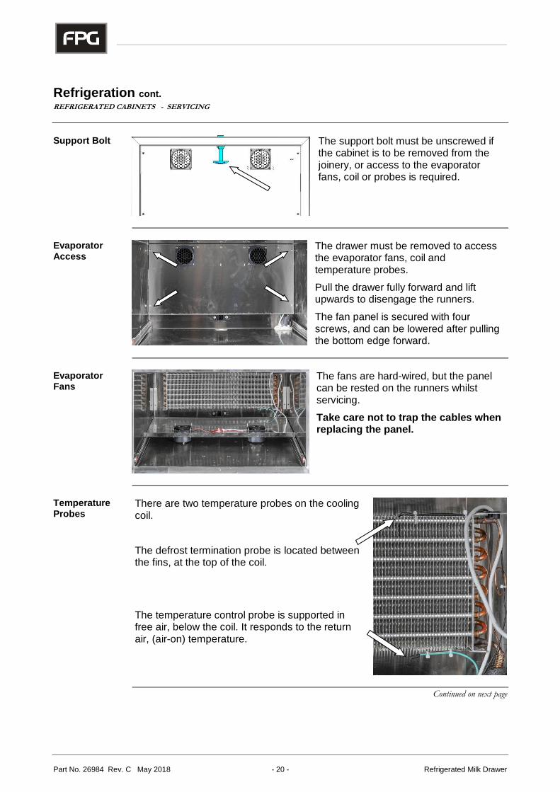
Support Bolt The support bolt must be unscrewed if
the cabinet is to be removed from the joinery, or access to the evaporator fans, coil or probes is required.
Evaporator Access
The drawer must be removed to access the evaporator fans, coil and temperature probes.
Pull the drawer fully forward and lift upwards to disengage the runners.
The fan panel is secured with four screws, and can be lowered after pulling the bottom edge forward.
Evaporator Fans
The fans are hard-wired, but the panel can be rested on the runners whilst servicing.
Take care not to trap the cables when replacing the panel.
Temperature Probes
There are two temperature probes on the cooling coil.
The defrost termination probe is located between the fins, at the top of the coil.
The temperature control probe is supported in free air, below the coil. It responds to the return air, (air-on) temperature.
Continued on next page
IL-C-DRW-A001/A003 - 21 - © Future Products Group
ON
Time
Refrigeration cont. REFRIGERATED CABINETS - SERVICING
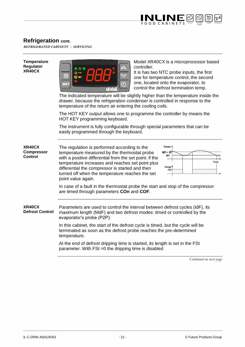
Temperature Regulator XR40CX
Model XR40CX is a microprocessor based controller. It is has two NTC probe inputs, the first one for temperature control, the second one, located onto the evaporator, to control the defrost termination temp.
The indicated temperature will be slightly higher than the temperature inside the drawer, because the refrigeration condenser is controlled in response to the temperature of the return air entering the cooling coils.
The HOT KEY output allows one to programme the controller by means the HOT KEY programming keyboard.
The instrument is fully configurable through special parameters that can be easily programmed through the keyboard.
XR40CX Compressor Control
The regulation is performed according to the temperature measured by the thermostat probe with a positive differential from the set point: if the temperature increases and reaches set point plus differential the compressor is started and then turned off when the temperature reaches the set point value again.
In case of a fault in the thermostat probe the start and stop of the compressor are timed through parameters COn and COF.
XR40CX Defrost Control
Parameters are used to control the interval between defrost cycles (IdF), its maximum length (MdF) and two defrost modes: timed or controlled by the evaporator’s probe (P2P).
In this cabinet, the start of the defrost cycle is timed, but the cycle will be terminated as soon as the defrost probe reaches the pre-determined temperature.
At the end of defrost dripping time is started, its length is set in the FSt parameter. With FSt =0 the dripping time is disabled
Continued on next page
Part No. 26984 Rev. C May 2018 - 22 - Refrigerated Milk Drawer
Refrigeration cont. REFRIGERATED CABINETS - SERVICING
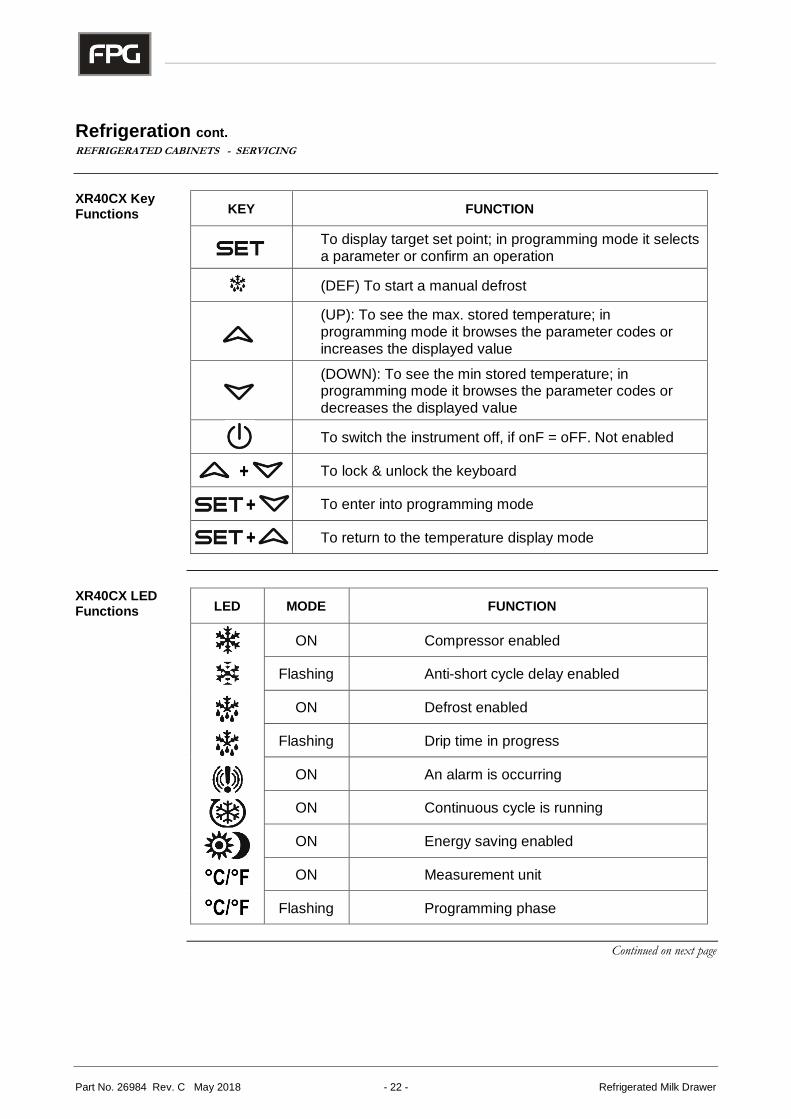
XR40CX Key Functions KEY FUNCTION
To display target set point; in programming mode it selects a parameter or confirm an operation
(DEF) To start a manual defrost
(UP): To see the max. stored temperature; in programming mode it browses the parameter codes or increases the displayed value
(DOWN): To see the min stored temperature; in programming mode it browses the parameter codes or decreases the displayed value
To switch the instrument off, if onF = oFF. Not enabled
To lock & unlock the keyboard
To enter into programming mode
To return to the temperature display mode
XR40CX LED Functions LED MODE FUNCTION
ON Compressor enabled
Flashing Anti-short cycle delay enabled
ON Defrost enabled
Flashing Drip time in progress
ON An alarm is occurring
ON Continuous cycle is running
ON Energy saving enabled
ON Measurement unit
Flashing Programming phase
Continued on next page
IL-C-DRW-A001/A003 - 23 - © Future Products Group
Refrigeration cont. REFRIGERATED CABINETS - SERVICING
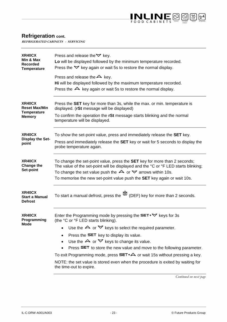
XR40CX Min & Max Recorded Temperature
Press and release the key.
Lo will be displayed followed by the minimum temperature recorded.
Press the key again or wait 5s to restore the normal display.
Press and release the key.
Hi will be displayed followed by the maximum temperature recorded.
Press the key again or wait 5s to restore the normal display.
XR40CX Reset Max/Min Temperature Memory
Press the SET key for more than 3s, while the max. or min. temperature is displayed. (rSt message will be displayed)
To confirm the operation the rSt message starts blinking and the normal temperature will be displayed.
XR40CX Display the Set-point
To show the set-point value, press and immediately release the SET key.
Press and immediately release the SET key or wait for 5 seconds to display the probe temperature again.
XR40CX Change the Set-point
To change the set-point value, press the SET key for more than 2 seconds; The value of the set-point will be displayed and the °C or °F LED starts blinking;
To change the set value push the or arrows within 10s.
To memorise the new set-point value push the SET key again or wait 10s.
XR40CX Start a Manual Defrost
To start a manual defrost, press the (DEF) key for more than 2 seconds.
XR40CX Programming Mode
Enter the Programming mode by pressing the keys for 3s (the °C or °F LED starts blinking).
• Use the or keys to select the required parameter.
• Press the key to display its value.
• Use the or keys to change its value.
• Press to store the new value and move to the following parameter.
To exit Programming mode, press or wait 15s without pressing a key.
NOTE: the set value is stored even when the procedure is exited by waiting for the time-out to expire.
Continued on next page
Part No. 26984 Rev. C May 2018 - 24 - Refrigerated Milk Drawer
Refrigeration cont. REFRIGERATED CABINETS - SERVICING
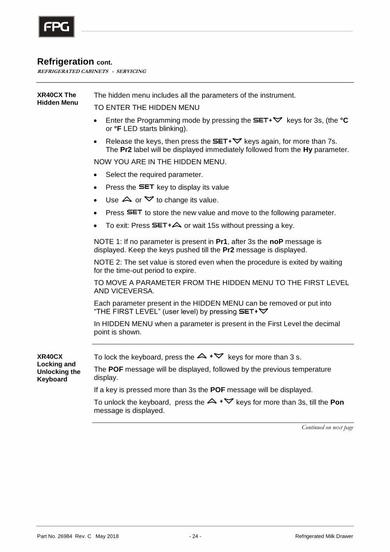
XR40CX The Hidden Menu
The hidden menu includes all the parameters of the instrument.
TO ENTER THE HIDDEN MENU
• Enter the Programming mode by pressing the keys for 3s, (the °C or °F LED starts blinking).
• Release the keys, then press the keys again, for more than 7s. The Pr2 label will be displayed immediately followed from the Hy parameter.
NOW YOU ARE IN THE HIDDEN MENU.
• Select the required parameter.
• Press the key to display its value
• Use or to change its value.
• Press to store the new value and move to the following parameter.
• To exit: Press or wait 15s without pressing a key.
NOTE 1: If no parameter is present in Pr1, after 3s the noP message is displayed. Keep the keys pushed till the Pr2 message is displayed.
NOTE 2: The set value is stored even when the procedure is exited by waiting for the time-out period to expire.
TO MOVE A PARAMETER FROM THE HIDDEN MENU TO THE FIRST LEVEL AND VICEVERSA.
Each parameter present in the HIDDEN MENU can be removed or put into “THE FIRST LEVEL” (user level) by pressing
In HIDDEN MENU when a parameter is present in the First Level the decimal point is shown.
XR40CX Locking and Unlocking the Keyboard
To lock the keyboard, press the keys for more than 3 s.
The POF message will be displayed, followed by the previous temperature display.
If a key is pressed more than 3s the POF message will be displayed.
To unlock the keyboard, press the keys for more than 3s, till the Pon message is displayed.
Continued on next page
IL-C-DRW-A001/A003 - 25 - © Future Products Group
Refrigeration cont. REFRIGERATED CABINETS - SERVICING
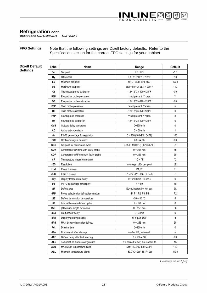
FPG Settings Note that the following settings are Dixell factory defaults. Refer to the
Specification section for the correct FPG settings for your cabinet.
Dixell Default Settings
Label Name Range Default
Set Set point LS÷ US -5.0
Hy Differential 0,1÷25.5°C/ 1÷ 255°F 2.0
LS Minimum set point -50°C÷SET/-58°F÷SET -50.0
US Maximum set point SET÷110°C/ SET ÷ 230°F 110
Ot Thermostat probe calibration -12÷12°C /-120÷120°F 0.0
P2P Evaporator probe presence n=not present; Y=pres. Y
OE Evaporator probe calibration -12÷12°C /-120÷120°F 0.0
P3P Third probe presence n=not present; Y=pres. n
O3 Third probe calibration -12÷12°C /-120÷120°F 0
P4P Fourth probe presence n=not present; Y=pres. n
O4 Fourth probe calibration -12÷12°C /-120÷120°F 0
OdS Outputs delay at start up 0÷255 min 0
AC Anti-short cycle delay 0 ÷ 50 min 1
rtr P1-P2 percentage for regulation 0 ÷ 100 (100=P1 , 0=P2) 100
CCt Continuous cycle duration 0.0÷24.0h 0.0
CCS Set point for continuous cycle (-55.0÷150,0°C) (-67÷302°F) -5
COn Compressor ON time with faulty probe 0 ÷ 255 min 15
COF Compressor OFF time with faulty probe 0 ÷ 255 min 30
CF Temperature measurement unit °C ÷ °F °C
rES Resolution in=integer; dE= dec.point dE
Lod Probe displayed P1;P2 P1
rEd2 X-REP display P1 - P2 - P3 - P4 - SEt - dtr P1
dLy Display temperature delay 0 ÷ 20.0 min (10 sec.) 0
dtr P1-P2 percentage for display 1 ÷ 99 50
tdF Defrost type EL=el. heater; in= hot gas EL
dFP Probe selection for defrost termination nP; P1; P2; P3; P4 P2
dtE Defrost termination temperature -50 ÷ 50 °C 8
IdF Interval between defrost cycles 1 ÷ 120 ore 6
MdF (Maximum) length for defrost 0 ÷ 255 min 30
dSd Start defrost delay 0÷99min 0
dFd Displaying during defrost rt, it, SEt, DEF it
dAd MAX display delay after defrost 0 ÷ 255 min 30
Fdt Draining time 0÷120 min 0
dPo First defrost after start-up n=after IdF; y=immed. n
dAF Defrost delay after fast freezing 0 ÷ 23h e 50’ 0.0
ALc Temperature alarms configuration rE= related to set; Ab = absolute Ab
ALU MAXIMUM temperature alarm Set÷110.0°C; Set÷230°F 110
ALL Minimum temperature alarm -50.0°C÷Set/ -58°F÷Set -50.0
Continued on next page
Part No. 26984 Rev. C May 2018 - 26 - Refrigerated Milk Drawer
Refrigeration cont. REFRIGERATED CABINETS - SERVICING
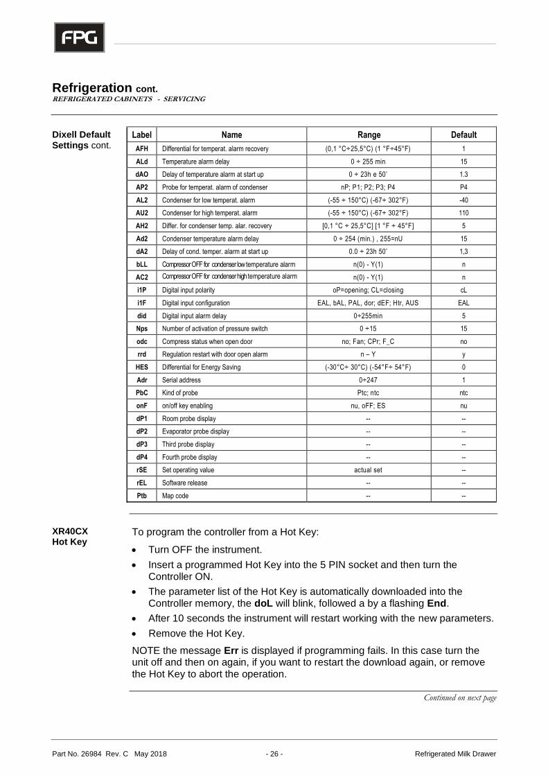
Dixell Default Settings cont.
Label Name Range Default
AFH Differential for temperat. alarm recovery (0,1 °C÷25,5°C) (1 °F÷45°F) 1
ALd Temperature alarm delay 0 ÷ 255 min 15
dAO Delay of temperature alarm at start up 0 ÷ 23h e 50’ 1.3
AP2 Probe for temperat. alarm of condenser nP; P1; P2; P3; P4 P4
AL2 Condenser for low temperat. alarm (-55 ÷ 150°C) (-67÷ 302°F) -40
AU2 Condenser for high temperat. alarm (-55 ÷ 150°C) (-67÷ 302°F) 110
AH2 Differ. for condenser temp. alar. recovery [0,1 °C ÷ 25,5°C] [1 °F ÷ 45°F] 5
Ad2 Condenser temperature alarm delay 0 ÷ 254 (min.) , 255=nU 15
dA2 Delay of cond. temper. alarm at start up 0.0 ÷ 23h 50’ 1,3
bLL Compressor OFF for condenser low temperature alarm n(0) - Y(1) n
AC2 Compressor OFF for condenser high temperature alarm n(0) - Y(1) n
i1P Digital input polarity oP=opening; CL=closing cL
i1F Digital input configuration EAL, bAL, PAL, dor; dEF; Htr, AUS EAL
did Digital input alarm delay 0÷255min 5
Nps Number of activation of pressure switch 0 ÷15 15
odc Compress status when open door no; Fan; CPr; F_C no
rrd Regulation restart with door open alarm n – Y y
HES Differential for Energy Saving (-30°C÷ 30°C) (-54°F÷ 54°F) 0
Adr Serial address 0÷247 1
PbC Kind of probe Ptc; ntc ntc
onF on/off key enabling nu, oFF; ES nu
dP1 Room probe display -- --
dP2 Evaporator probe display -- --
dP3 Third probe display -- --
dP4 Fourth probe display -- --
rSE Set operating value actual set --
rEL Software release -- --
Ptb Map code -- --
XR40CX Hot Key
To program the controller from a Hot Key:
• Turn OFF the instrument.
• Insert a programmed Hot Key into the 5 PIN socket and then turn the Controller ON.
• The parameter list of the Hot Key is automatically downloaded into the Controller memory, the doL will blink, followed a by a flashing End.
• After 10 seconds the instrument will restart working with the new parameters.
• Remove the Hot Key.
NOTE the message Err is displayed if programming fails. In this case turn the unit off and then on again, if you want to restart the download again, or remove the Hot Key to abort the operation.
Continued on next page
IL-C-DRW-A001/A003 - 27 - © Future Products Group
Refrigeration cont. REFRIGERATED CABINETS - SERVICING
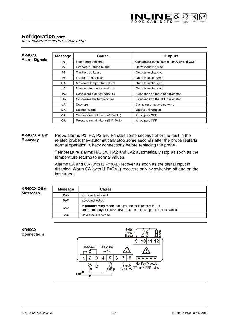
XR40CX Alarm Signals
Message Cause Outputs
P1 Room probe failure Compressor output acc. to par. Con and COF
P2 Evaporator probe failure Defrost end is timed
P3 Third probe failure Outputs unchanged
P4 Fourth probe failure Outputs unchanged
HA Maximum temperature alarm Outputs unchanged.
LA Minimum temperature alarm Outputs unchanged.
HA2 Condenser high temperature It depends on the Ac2 parameter
LA2 Condenser low temperature It depends on the bLL parameter
dA Door open Compressor according to rrd
EA External alarm Output unchanged.
CA Serious external alarm (i1 F=bAL) All outputs OFF.
CA Pressure switch alarm (i1 F=PAL) All outputs OFF
XR40CX Alarm Recovery
Probe alarms P1, P2, P3 and P4 start some seconds after the fault in the related probe; they automatically stop some seconds after the probe restarts normal operation. Check connections before replacing the probe.
Temperature alarms HA, LA, HA2 and LA2 automatically stop as soon as the
temperature returns to normal values.
Alarms EA and CA (with i1 F=bAL) recover as soon as the digital input is disabled. Alarm CA (with i1 F=PAL) recovers only by switching off and on the instrument.
XR40CX Other Messages
Message Cause
Pon Keyboard unlocked.
PoF Keyboard locked
noP In programming mode: none parameter is present in Pr1
On the display or in dP2, dP3, dP4: the selected probe is not enabled
noA No alarm is recorded.
XR40CX Connections
Part No. 26984 Rev. C May 2018 - 28 - Refrigerated Milk Drawer
SPECIFICATIONS
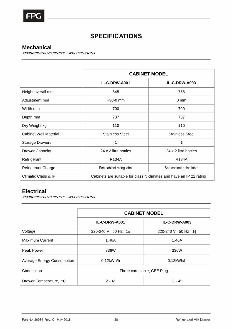
Mechanical REFRIGERATED CABINETS - SPECIFICATIONS
CABINET MODEL
IL-C-DRW-A001 IL-C-DRW-A003
Height overall mm 845 756
Adjustment mm +30-0 mm 0 mm
Width mm 700 700
Depth mm 737 737
Dry Weight kg 110 110
Cabinet Well Material Stainless Steel Stainless Steel
Storage Drawers 1 1
Drawer Capacity 24 x 2 litre bottles 24 x 2 litre bottles
Refrigerant R134A R134A
Refrigerant Charge See cabinet rating label See cabinet rating label
Climatic Class & IP Cabinets are suitable for class N climates and have an IP 22 rating
Electrical REFRIGERATED CABINETS - SPECIFICATIONS
CABINET MODEL
IL-C-DRW-A001 IL-C-DRW-A003
Voltage 220-240 V 50 Hz 1 220-240 V 50 Hz 1
Maximum Current 1.46A 1.46A
Peak Power 336W 336W
Average Energy Consumption 0.12kWh/h 0.12kWh/h
Connection Three core cable, CEE Plug
Drawer Temperature, C 2 - 4 2 - 4
IL-C-DRW-A001/A003 - 29 - © Future Products Group
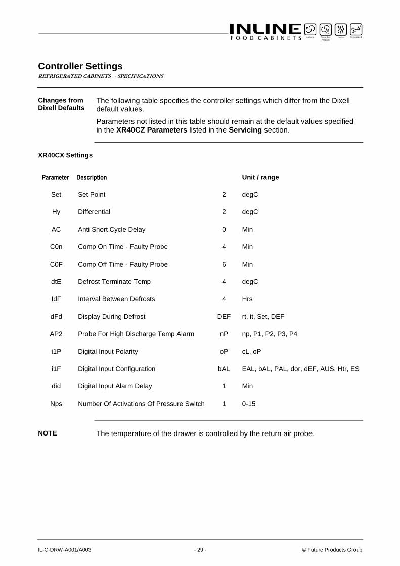
Controller Settings REFRIGERATED CABINETS - SPECIFICATIONS
Changes from Dixell Defaults
The following table specifies the controller settings which differ from the Dixell default values.
Parameters not listed in this table should remain at the default values specified in the XR40CZ Parameters listed in the Servicing section.
XR40CX Settings
Parameter Description Unit / range
Set Set Point 2 degC
Hy Differential 2 degC
AC Anti Short Cycle Delay 0 Min
C0n Comp On Time - Faulty Probe 4 Min
C0F Comp Off Time - Faulty Probe 6 Min
dtE Defrost Terminate Temp 4 degC
IdF Interval Between Defrosts 4 Hrs
dFd Display During Defrost DEF rt, it, Set, DEF
AP2 Probe For High Discharge Temp Alarm nP np, P1, P2, P3, P4
i1P Digital Input Polarity oP cL, oP
i1F Digital Input Configuration bAL EAL, bAL, PAL, dor, dEF, AUS, Htr, ES
did Digital Input Alarm Delay 1 Min
Nps Number Of Activations Of Pressure Switch 1 0-15
NOTE The temperature of the drawer is controlled by the return air probe.
Part No. 26984 Rev. C May 2018 - 30 - Refrigerated Milk Drawer
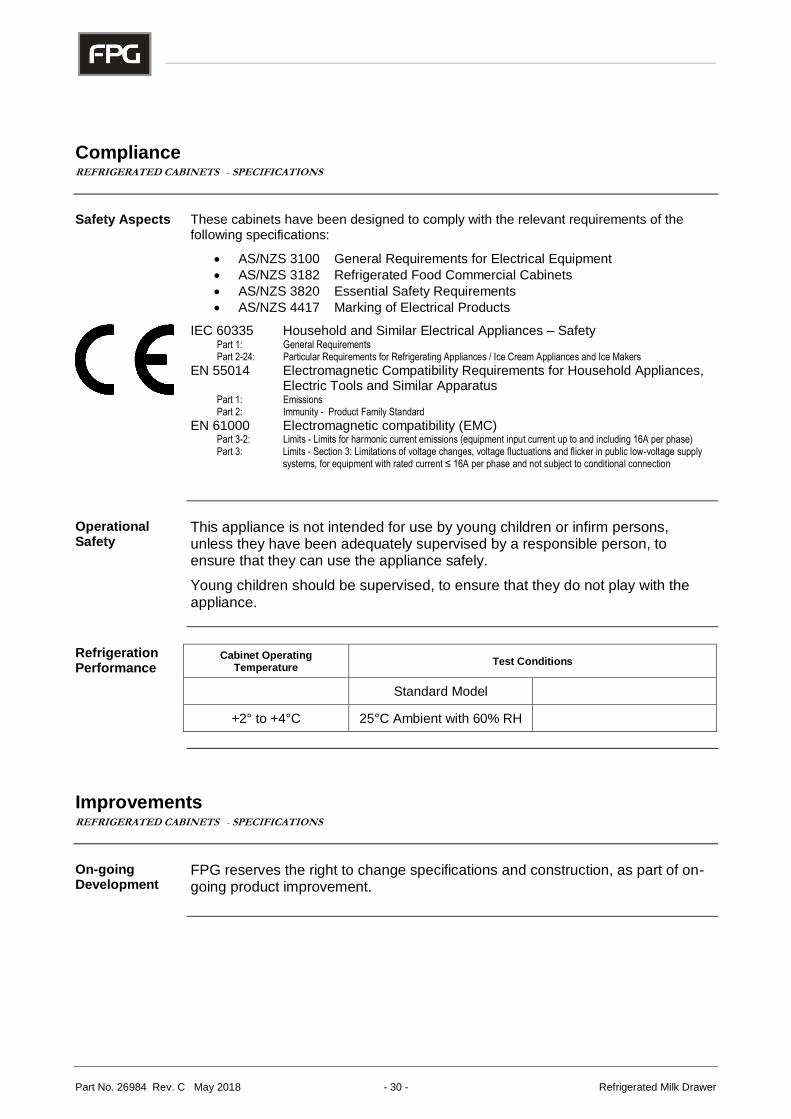
Compliance REFRIGERATED CABINETS - SPECIFICATIONS
Safety Aspects
These cabinets have been designed to comply with the relevant requirements of the following specifications:
• AS/NZS 3100 General Requirements for Electrical Equipment
• AS/NZS 3182 Refrigerated Food Commercial Cabinets
• AS/NZS 3820 Essential Safety Requirements
• AS/NZS 4417 Marking of Electrical Products
IEC 60335 Household and Similar Electrical Appliances – Safety Part 1: General Requirements Part 2-24: Particular Requirements for Refrigerating Appliances / Ice Cream Appliances and Ice Makers
EN 55014 Electromagnetic Compatibility Requirements for Household Appliances, Electric Tools and Similar Apparatus
Part 1: Emissions Part 2: Immunity - Product Family Standard
EN 61000 Electromagnetic compatibility (EMC) Part 3-2: Limits - Limits for harmonic current emissions (equipment input current up to and including 16A per phase) Part 3: Limits - Section 3: Limitations of voltage changes, voltage fluctuations and flicker in public low-voltage supply
systems, for equipment with rated current ≤ 16A per phase and not subject to conditional connection
Operational Safety
This appliance is not intended for use by young children or infirm persons, unless they have been adequately supervised by a responsible person, to ensure that they can use the appliance safely.
Young children should be supervised, to ensure that they do not play with the appliance.
Refrigeration Performance
Cabinet Operating Temperature
Test Conditions
Standard Model
+2° to +4°C 25°C Ambient with 60% RH
Improvements REFRIGERATED CABINETS - SPECIFICATIONS
On-going Development
FPG reserves the right to change specifications and construction, as part of on-going product improvement.
IL-C-DRW-A001/A003 - 31 - © Future Products Group
ELECTRICAL CIRCUIT DIAGRAMS
Model: IL-C-DRW-A001/A003 Refrigerated Milk Drawer
Part No. 26984 Rev. C May 2018 - 32 - Refrigerated Milk Drawer
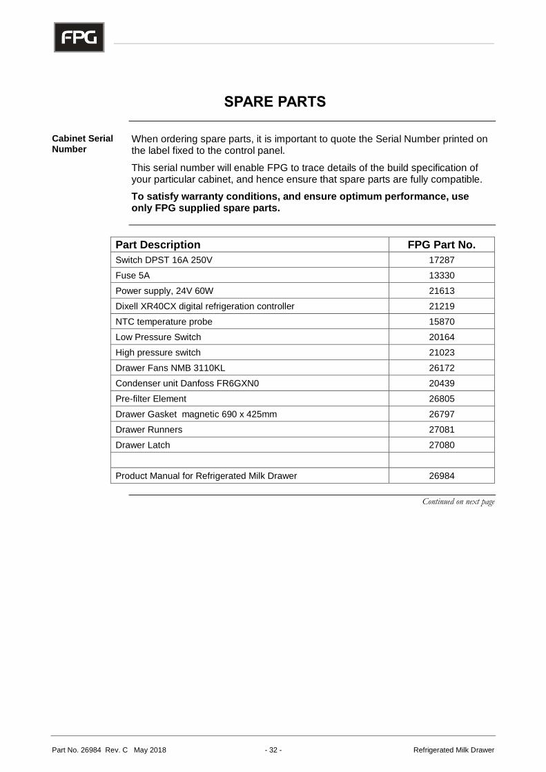
SPARE PARTS
Cabinet Serial Number
When ordering spare parts, it is important to quote the Serial Number printed on the label fixed to the control panel.
This serial number will enable FPG to trace details of the build specification of your particular cabinet, and hence ensure that spare parts are fully compatible.
To satisfy warranty conditions, and ensure optimum performance, use only FPG supplied spare parts.
Part Description FPG Part No.
Switch DPST 16A 250V 17287
Fuse 5A 13330
Power supply, 24V 60W 21613
Dixell XR40CX digital refrigeration controller 21219
NTC temperature probe 15870
Low Pressure Switch 20164
High pressure switch 21023
Drawer Fans NMB 3110KL 26172
Condenser unit Danfoss FR6GXN0 20439
Pre-filter Element 26805
Drawer Gasket magnetic 690 x 425mm 26797
Drawer Runners 27081
Drawer Latch 27080
Product Manual for Refrigerated Milk Drawer 26984
Continued on next page
IL-C-DRW-A001/A003 - 33 - © Future Products Group
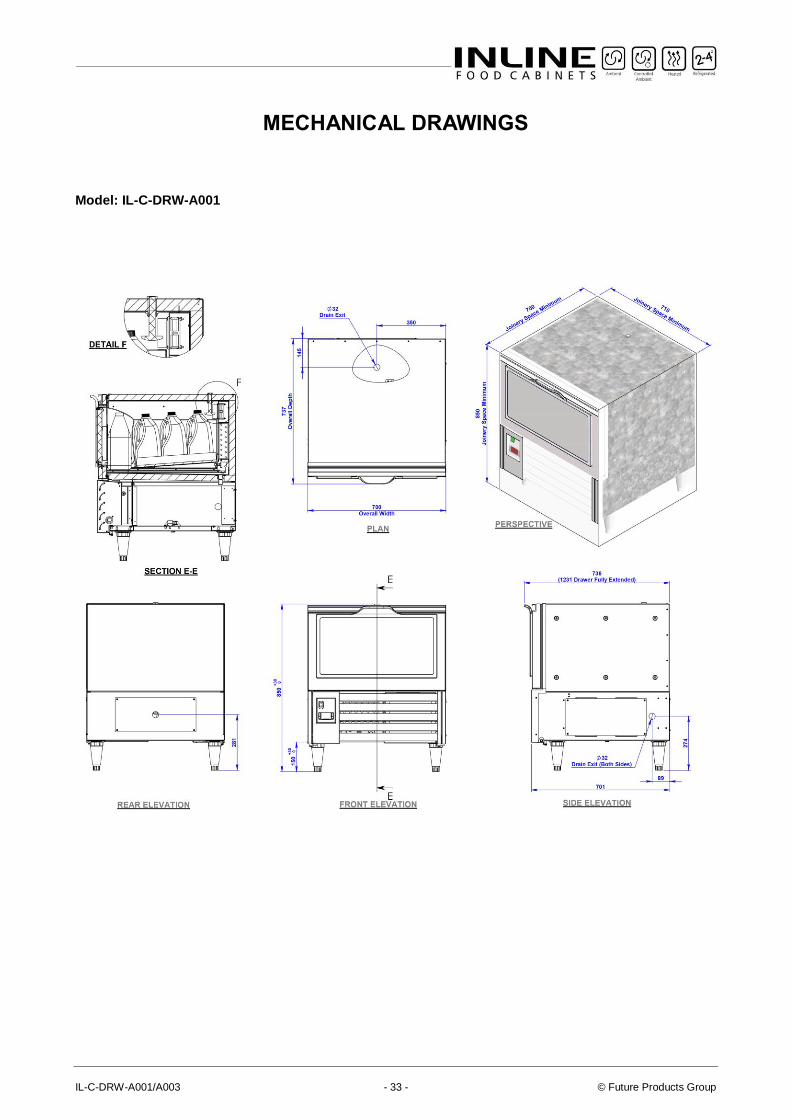
MECHANICAL DRAWINGS
Model: IL-C-DRW-A001
Part No. 26984 Rev. C May 2018 - 34 - Refrigerated Milk Drawer
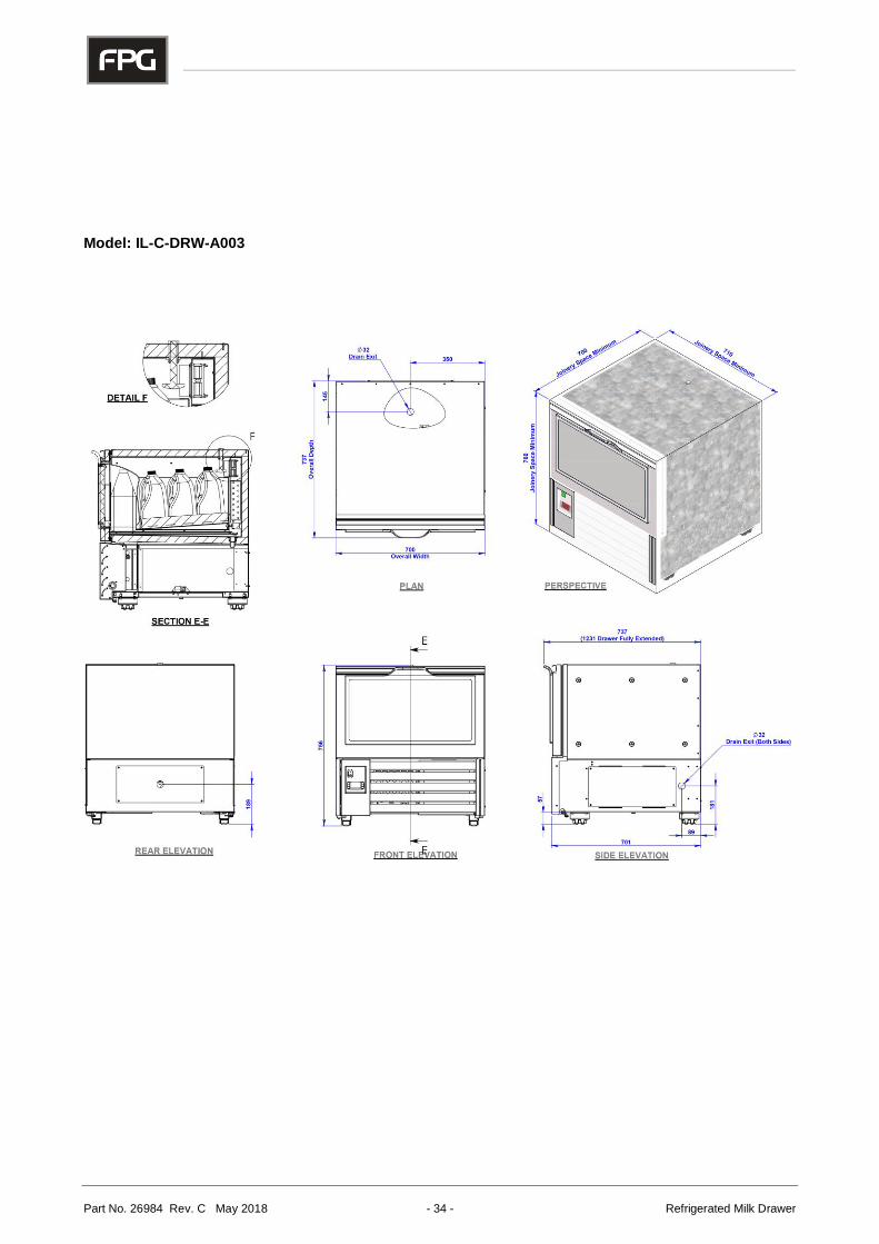
Model: IL-C-DRW-A003
IL-C-DRW-A001/A003 - 35 - © Future Products Group
Part No. 26984 Rev. C May 2018
For full contact details please visit the Contacts page on FPGWORLD.COM or email us at [email protected] In line with policy to continually develop and improve its products, Future Products Group reserves the right to change specifications and design without notice.
AUSTRALIA
T 1800 813 745
CHINA | ASIA
T +86 21 3351 3390
EUROPE
T +31 6 5253 4769
INDIA
T +91 98 1020 5058
INDONESIA
E [email protected] T +62 811 152 7288
UAE
T +971 4 340 4795
NEW ZEALAND
E [email protected] T 0800 367 374
UNITED KINGDOM
E [email protected] T 0808 234 7922