Embed Size (px)
Citation preview

Refrigeration & Air Conditioning (MAB-4533)
Chapter- 9
Air cycle refrigeration systems
Refrigeration & Air Conditioning (MAB-4533)
The objectives of this lesson are to :
1.Reverse Carnot cycle & its limitations
2.Reverse Brayton cycle – Ideal & Actual
3.Aircraft refrigeration cycles, namely Simple system, Bootstrap system,
Regenerative system, etc.
Objectives of the lesson
At the end of the lesson, the student should be able to:
1.Describe various air cycle refrigeration systems
2.State the assumptions made in the analyses of air cycle systems
3.Show the cycles on T-s diagrams
4.Perform various cycle calculations
5.State the significance of Dry Air Rated Temperature
Introduction
Refrigeration & Air Conditioning (MAB-4533)
Air cycle refrigeration systems belong to the general class of gas
cycle refrigeration systems, in which a gas is used as the working
fluid. The gas does not undergo any phase change during the
cycle, consequently, all the internal heat transfer processes are
sensible heat transfer processes. Gas cycle refrigeration systems
find applications in air craft cabin cooling and also in the
liquefaction of various gases.
Air Standard Cycle analysis
Air cycle refrigeration system analysis is considerably simplified if one makes the following assumptions: i.The working fluid is a fixed mass of air that behaves as an ideal gas ii.The cycle is assumed to be a closed loop cycle with all inlet and exhaust processes of open loop cycles being replaced by heat transfer processes to or from the environment iii.All the processes within the cycle are reversible, i.e., the cycle is internally reversible iv.The specific heat of air remains constant throughout the cycle
An analysis with the above assumptions is called as cold Air Standard Cycle (ASC) analysis. This analysis yields reasonably accurate results for most of the cycles and processes encountered in air cycle refrigeration systems. However, the analysis fails when one considers a cycle consisting of a throttling process, as the temperature drop during throttling is zero for an ideal gas, whereas the actual cycles depend exclusively on the real gas behavior to produce refrigeration during throttling
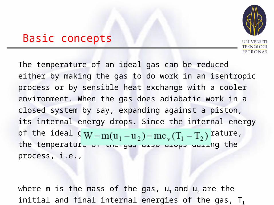
The temperature of an ideal gas can be reduced either by making the gas to do
work in an isentropic process or by sensible heat exchange with a cooler
environment. When the gas does adiabatic work in a closed system by say,
expanding against a piston, its internal energy drops. Since the internal energy
of the ideal gas depends only on its temperature, the temperature of the gas
also drops during the process, i.e.,
where m is the mass of the gas, u1 and u2 are the initial and final internal
energies of the gas, T1 and T2
are the initial and final temperatures and cv is the
specific heat at constant volume.
Basic concepts
Refrigeration & Air Conditioning (MAB-4533)
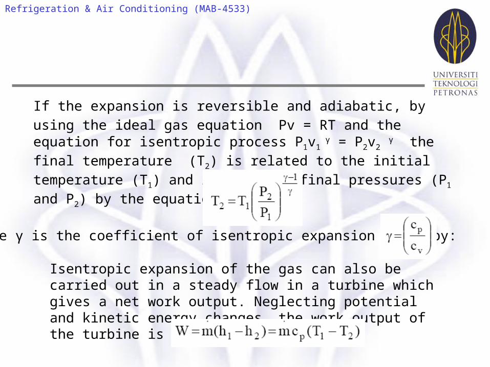
If the expansion is reversible and adiabatic, by using the ideal gas equation Pv = RT and the equation for isentropic process P1v1
γ = P2v2 γ the final
temperature (T2) is related to the initial temperature (T1) and initial and final
pressures (P1 and P2) by the equation:
where γ is the coefficient of isentropic expansion given by:
Isentropic expansion of the gas can also be carried out in a steady flow in a turbine which gives a net work output. Neglecting potential and kinetic energy changes, the work output of the turbine is given by:
Refrigeration & Air Conditioning (MAB-4533)
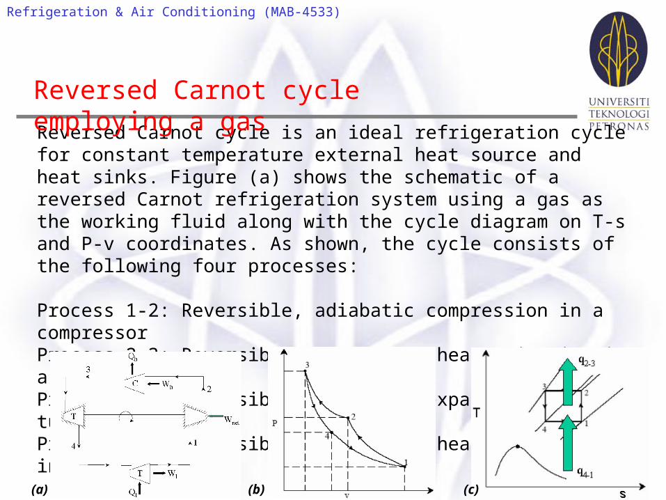
Reversed Carnot cycle is an ideal refrigeration cycle for constant temperature external heat source and heat sinks. Figure (a) shows the schematic of a reversed Carnot refrigeration system using a gas as the working fluid along with the cycle diagram on T-s and P-v coordinates. As shown, the cycle consists of the following four processes:
Process 1-2: Reversible, adiabatic compression in a compressor Process 2-3: Reversible, isothermal heat rejection in a compressor Process 3-4: Reversible, adiabatic expansion in a turbine Process 4-1: Reversible, isothermal heat absorption in a turbine
Reversed Carnot cycle employing a gas
(a) (b) (c)
Refrigeration & Air Conditioning (MAB-4533)
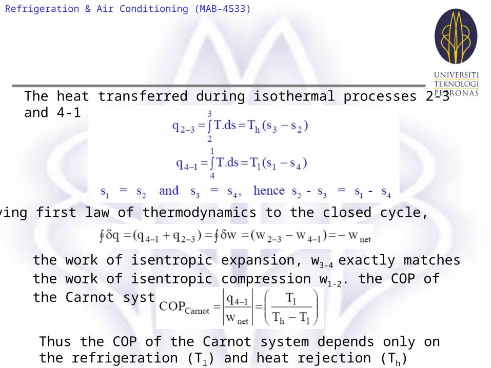
The heat transferred during isothermal processes 2-3 and 4-1 are given by:
Applying first law of thermodynamics to the closed cycle,
the work of isentropic expansion, w3-4 exactly matches the work of isentropic compression w1-2. the COP of the Carnot system is given by:
Thus the COP of the Carnot system depends only on the refrigeration (Tl) and heat rejection (Th) temperatures only.
Refrigeration & Air Conditioning (MAB-4533)
Carnot cycle is an idealization and it suffers from several practical
limitations. One of the main difficulties with Carnot cycle employing a gas
is the difficulty of achieving isothermal heat transfer during processes 2-3
and 4-1. For a gas to have heat transfer isothermally, it is essential to carry
out work transfer from or to the system when heat is transferred to the
system (process 4-1) or from the system (process 2-3). This is difficult to
achieve in practice. In addition, the volumetric refrigeration capacity of the
Carnot system is very small leading to large compressor displacement,
which gives rise to large frictional effects. All actual processes are
irreversible, hence completely reversible cycles are idealizations only.
Limitations of Carnot cycle
Refrigeration & Air Conditioning (MAB-4533)
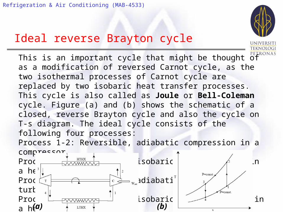
This is an important cycle that might be thought of as a modification of reversed Carnot cycle, as the two isothermal processes of Carnot cycle are replaced by two isobaric heat transfer processes. This cycle is also called as Joule or Bell-Coleman cycle. Figure (a) and (b) shows the schematic of a closed, reverse Brayton cycle and also the cycle on T-s diagram. The ideal cycle consists of the following four processes: Process 1-2: Reversible, adiabatic compression in a compressor Process 2-3: Reversible, isobaric heat rejection in a heat exchanger Process 3-4: Reversible, adiabatic expansion in a turbine Process 4-1: Reversible, isobaric heat absorption in a heat exchanger
Ideal reverse Brayton cycle
(a) (b)
Refrigeration & Air Conditioning (MAB-4533)
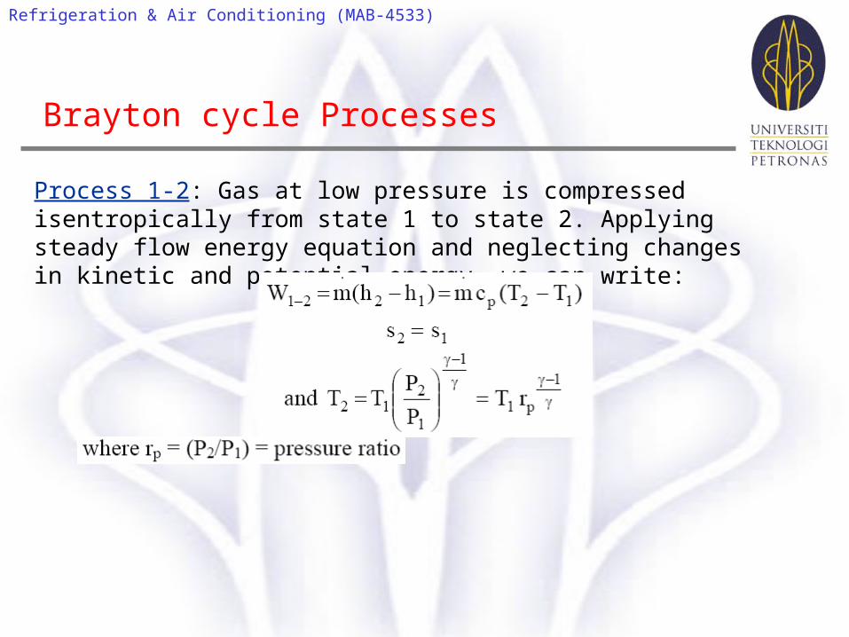
Process 1-2: Gas at low pressure is compressed isentropically from state 1 to state 2. Applying steady flow energy equation and neglecting changes in kinetic and potential energy, we can write:
Brayton cycle Processes
Refrigeration & Air Conditioning (MAB-4533)
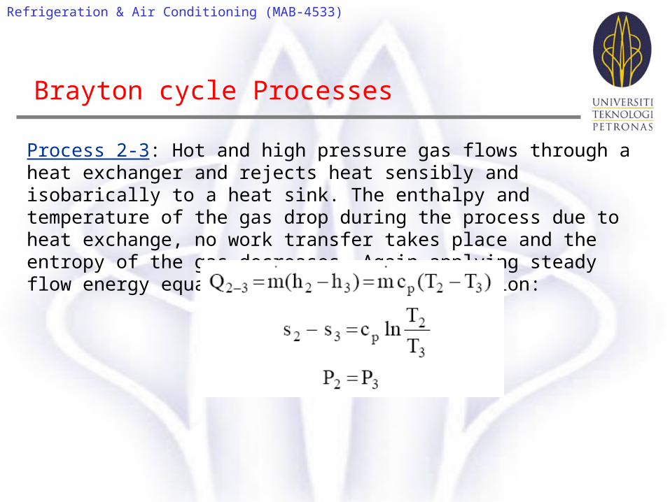
Process 2-3: Hot and high pressure gas flows through a heat exchanger and rejects heat sensibly and isobarically to a heat sink. The enthalpy and temperature of the gas drop during the process due to heat exchange, no work transfer takes place and the entropy of the gas decreases. Again applying steady flow energy equation and second T ds equation:
Brayton cycle Processes
Refrigeration & Air Conditioning (MAB-4533)
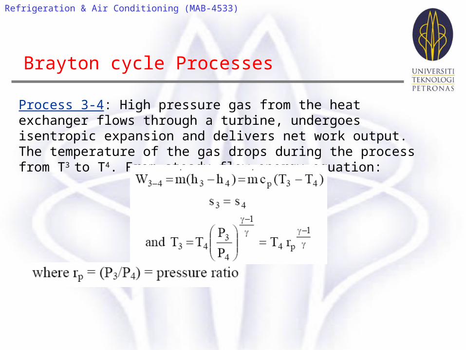
Process 3-4: High pressure gas from the heat exchanger flows through a turbine, undergoes isentropic expansion and delivers net work output. The temperature of the gas drops during the process from T3 to T4. From steady flow energy equation:
Brayton cycle Processes
Refrigeration & Air Conditioning (MAB-4533)
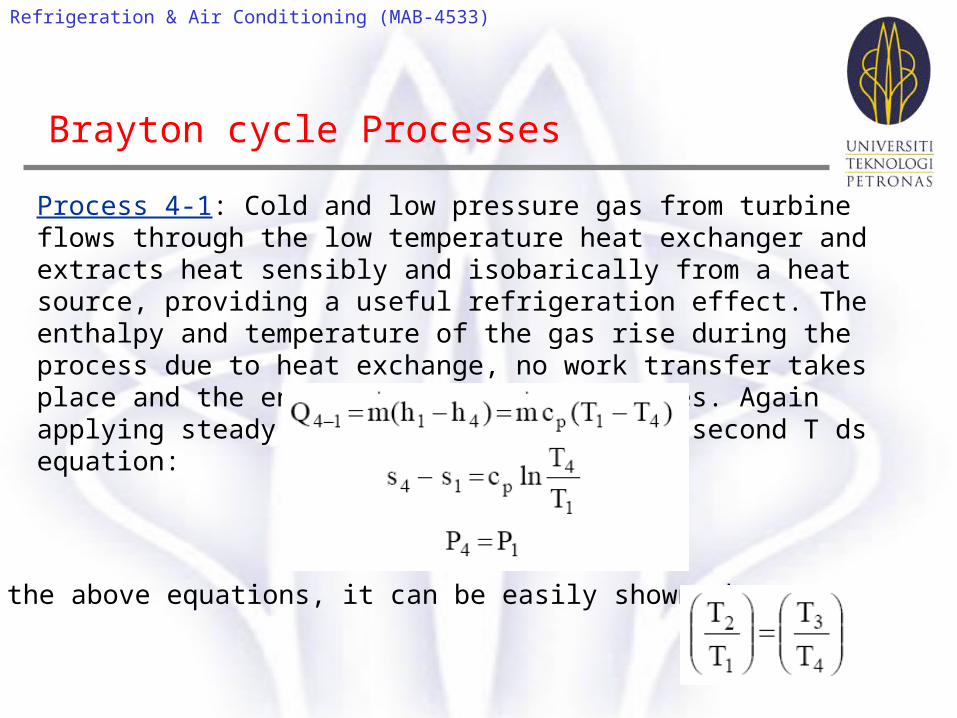
Process 4-1: Cold and low pressure gas from turbine flows through the low temperature heat exchanger and extracts heat sensibly and isobarically from a heat source, providing a useful refrigeration effect. The enthalpy and temperature of the gas rise during the process due to heat exchange, no work transfer takes place and the entropy of the gas increases. Again applying steady flow energy equation and second T ds equation:
Brayton cycle Processes
From the above equations, it can be easily shown that:
Refrigeration & Air Conditioning (MAB-4533)
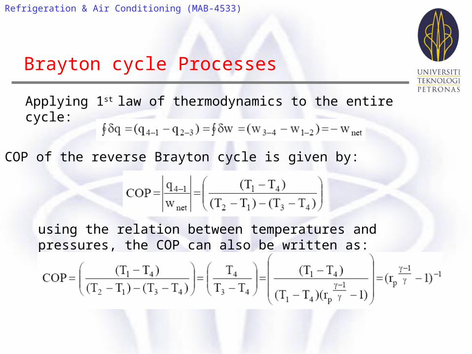
Applying 1st law of thermodynamics to the entire cycle:
Brayton cycle Processes
The COP of the reverse Brayton cycle is given by:
using the relation between temperatures and pressures, the COP can also be written as:
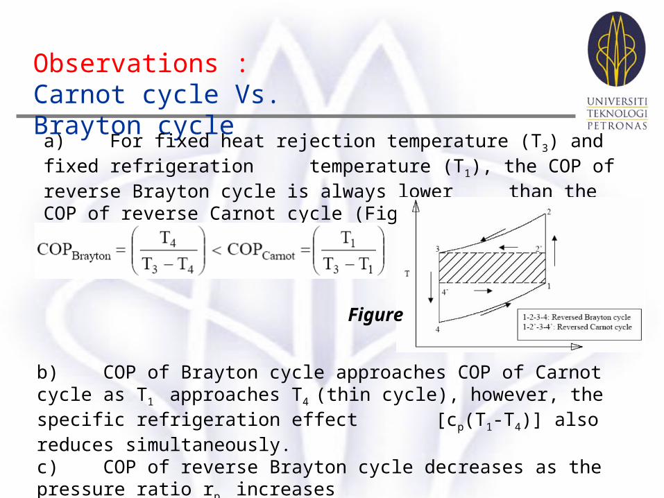
Observations :Carnot cycle Vs. Brayton cycle
a) For fixed heat rejection temperature (T3) and fixed refrigeration temperature (T1), the COP of reverse Brayton cycle is always lower than the COP of reverse Carnot cycle (Figure), that is :
Figure
b) COP of Brayton cycle approaches COP of Carnot cycle as T1
approaches T4 (thin cycle), however, the specific refrigeration effect [cp(T1-
T4)] also reduces simultaneously. c) COP of reverse Brayton cycle decreases as the pressure ratio rp
increases
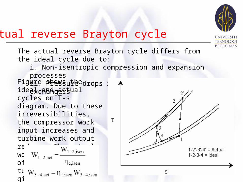
Actual reverse Brayton cycle
The actual reverse Brayton cycle differs from the ideal cycle due to: i. Non-isentropic compression and expansion processes ii. Pressure drops in cold and hot heat exchangers
Figure shows the ideal and actual cycles on T-s diagram. Due to these irreversibilities, the compressor work input increases and turbine work output reduces. The actual work transfer rates of compressor and turbine are then given by:
Actual reverse Brayton cycle
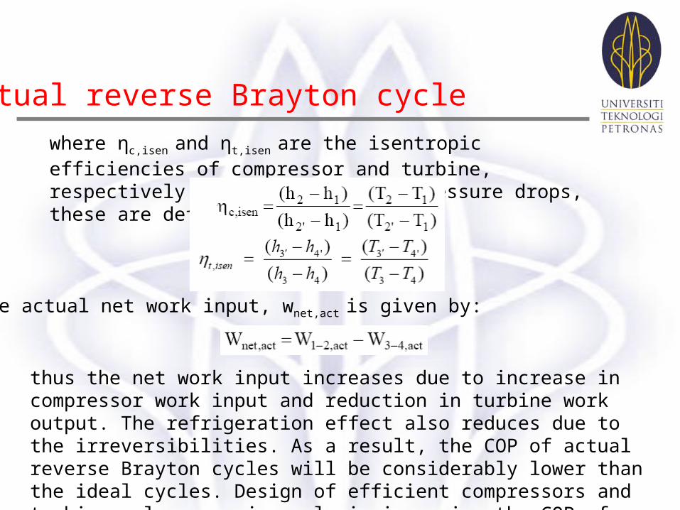
where ηc,isen and ηt,isen
are the isentropic efficiencies of compressor and turbine, respectively. In the absence of pressure drops, these are defined as:
The actual net work input, wnet,act is given by:
thus the net work input increases due to increase in compressor work input and reduction in turbine work output. The refrigeration effect also reduces due to the irreversibilities. As a result, the COP of actual reverse Brayton cycles will be considerably lower than the ideal cycles. Design of efficient compressors and turbines plays a major role in improving the COP of the system.
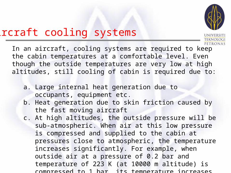
Aircraft cooling systems
In an aircraft, cooling systems are required to keep the cabin temperatures at a comfortable level. Even though the outside temperatures are very low at high altitudes, still cooling of cabin is required due to:
a. Large internal heat generation due to occupants, equipment etc. b. Heat generation due to skin friction caused by the fast moving aircraft c. At high altitudes, the outside pressure will be sub-atmospheric. When
air at this low pressure is compressed and supplied to the cabin at pressures close to atmospheric, the temperature increases significantly. For example, when outside air at a pressure of 0.2 bar and temperature of 223 K (at 10000 m altitude) is compressed to 1 bar, its temperature increases to about 353 K. If the cabin is maintained at 0.8 bar, the temperature will be about 332 K. This effect is called as ram effect. This effect adds heat to the cabin, which needs to be taken out by the cooling system.
d. Solar radiation
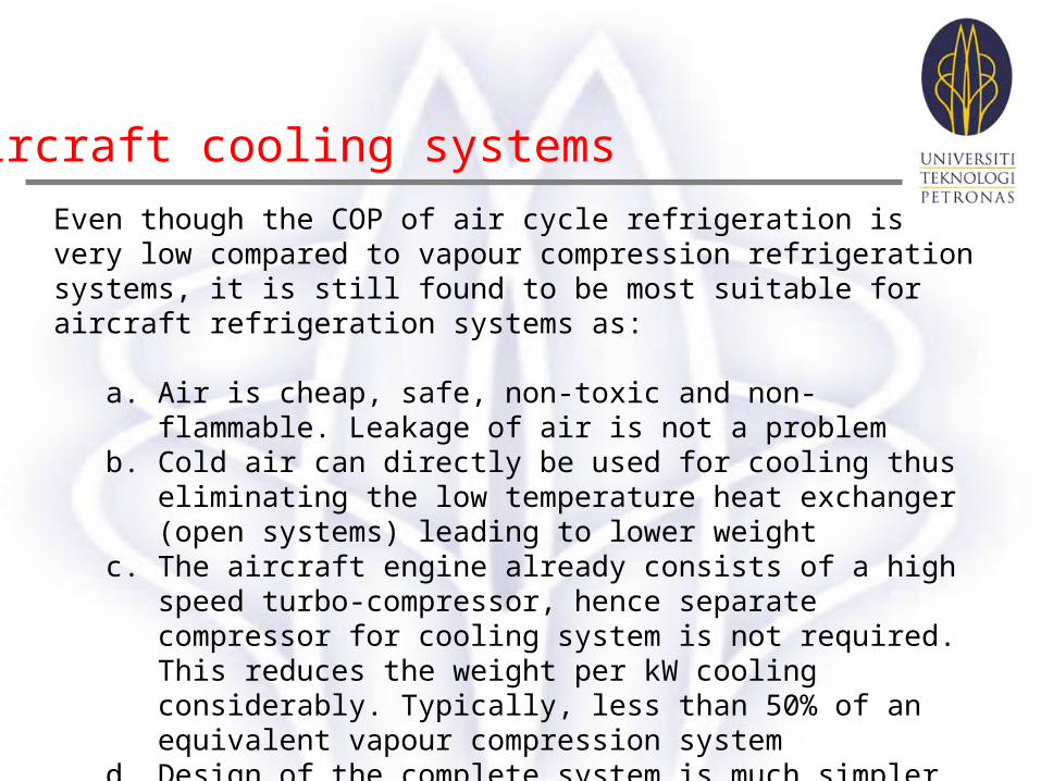
Aircraft cooling systems
Even though the COP of air cycle refrigeration is very low compared to vapour compression refrigeration systems, it is still found to be most suitable for aircraft refrigeration systems as:
a. Air is cheap, safe, non-toxic and non-flammable. Leakage of air is not a problem
b. Cold air can directly be used for cooling thus eliminating the low temperature heat exchanger (open systems) leading to lower weight
c. The aircraft engine already consists of a high speed turbo-compressor, hence separate compressor for cooling system is not required. This reduces the weight per kW cooling considerably. Typically, less than 50% of an equivalent vapour compression system
d. Design of the complete system is much simpler due to low pressures. Maintenance required is also less.
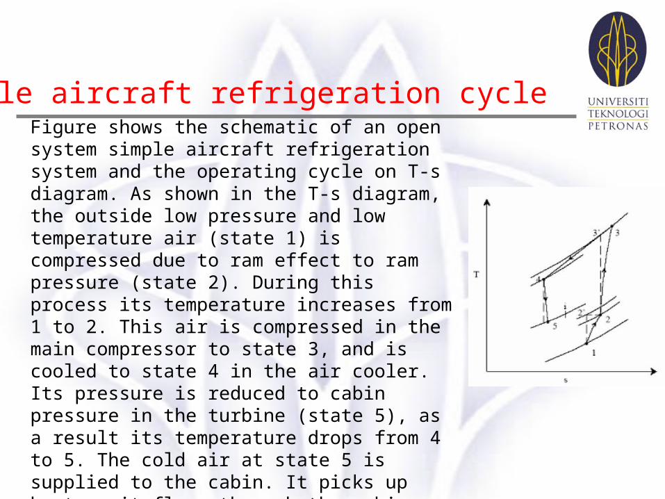
Simple aircraft refrigeration cycle Figure shows the schematic of an open system simple aircraft refrigeration system and the operating cycle on T-s diagram. As shown in the T-s diagram, the outside low pressure and low temperature air (state 1) is compressed due to ram effect to ram pressure (state 2). During this process its temperature increases from 1 to 2. This air is compressed in the main compressor to state 3, and is cooled to state 4 in the air cooler. Its pressure is reduced to cabin pressure in the turbine (state 5), as a result its temperature drops from 4 to 5. The cold air at state 5 is supplied to the cabin. It picks up heat as it flows through the cabin providing useful cooling effect. The power output of the turbine is used to drive the fan, which maintains the required air flow over the air cooler. This simple system is good for ground cooling (when the aircraft is not moving) as fan can continue to maintain airflow over the air cooler.
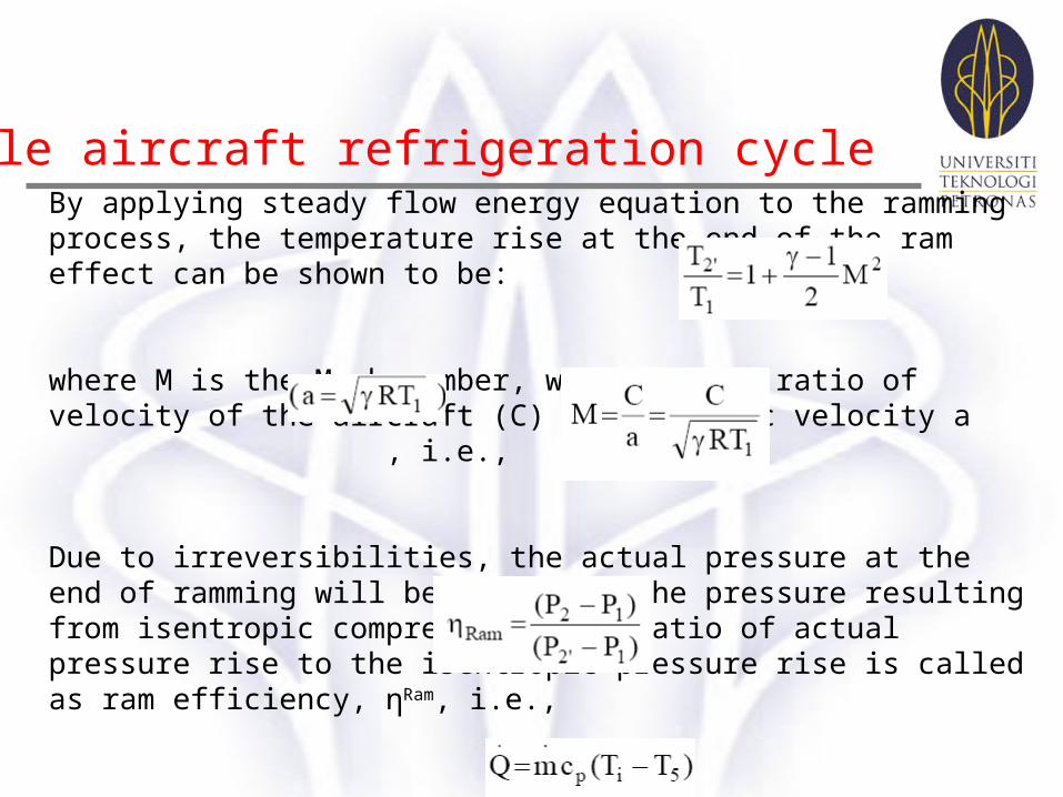
Simple aircraft refrigeration cycle By applying steady flow energy equation to the ramming process, the temperature rise at the end of the ram effect can be shown to be:
where M is the Mach number, which is the ratio of velocity of the aircraft (C) to the sonic velocity a , i.e.,
Due to irreversibilities, the actual pressure at the end of ramming will be less than the pressure resulting from isentropic compression. The ratio of actual pressure rise to the isentropic pressure rise is called as ram efficiency, ηRam, i.e.,
The refrigeration capacity of the simple aircraft cycle discussed, is given by:
Refrigeration & Air Conditioning (MAB-4533)
In these chapters, the following topics have been discussed:
• Standard Air cycle refrigeration systems
•Actual Air cycle refrigeration systems
• Reversed Carnot cycle
•Reversed Brayton Cycle
•Aircraft Cooling Systems
Summary