Embed Size (px)
Citation preview

What to Include in your Binder – Division C
• “1 Page” Cheat Sheet – Quick reference • Units and constants
– M, m, k, p, n, … – Resistivity – Derivation of SI Units
• Detailed sections – Basic DC – Battery – Types of components – Basic Circuits – Sections for different circuit analysis; Mesh, Nodal, Thevenins, Norton, – Conversion of units – Wheatstone Bridge – Capacitor Theory – History – Digital Logic
• Definitions
2

Div. C Topics • DC circuit concepts, definitions and principles
– Voltage, Current, EMF, Resistance – Series, Parallel – Voltage Dividers – Impedance Matching – History
3

Possible Types of Problems
4
• Battery polarity
• Parallel versus series
Describe what ill happen to the total
resistance and conductance when you add
additional resistors in parallel

History • Named SI Units only
– Ohm
– Volt
– Ampere
– Henry
– Coulomb
– …. ( this is not a complete list)
• Who, When, Why, What style of questions
• Related Laws
5

6
Name[3][4] Life Nationality Quantity[5] SI unit[Note 2]
André-Marie Ampère[6] 1775–1836 French Electric current [7] (Base unit)
William Thomson, 1st Baron Kelvin[8] 1824–1907 British (Scottish) Thermodynamic temperature[9] (Base unit)
Blaise Pascal[10] 1623–1662 French Pressure[11] pascal (Pa)
Isaac Newton[12] 1643–1727 British (English) Force[13] newton (N)
Anders Celsius[14] 1701–1744 Swedish Temperature[15] degree Celsius (°C)
Charles-Augustin de Coulomb[16] 1736–1806 French Electric charge[17] coulomb (C)
James Watt[18] 1736–1819 British (Scottish) Power[19] watt (W)
Alessandro Volta [20] 1745–1827 Italian Electric potential[21] volt (V)
Georg Simon Ohm[22] 1789–1855 German Electrical resistance[23] ohm (Ω)
Michael Faraday[24] 1791–1867 British (English) Capacitance[25] farad (F)
Joseph Henry[26] 1797–1878 American Inductance[27] henry (H)
Wilhelm Eduard Weber[28] 1804–1891 German Magnetic flux[29] weber (Wb)
Ernst Werner von Siemens [30] 1816–1892 German Conductance[31] siemens (S)
James Prescott Joule[32] 1818–1889 British (English) Energy[33] joule (J)
Antoine Henri Becquerel[34] 1852–1908 French Radioactivity[35] becquerel (Bq)
Nikola Tesla [36] 1856–1943
Serbian[Note 3]-American Magnetic flux density[37] tesla (T)
Heinrich Rudolf Hertz[38] 1857–1894 German Frequency[39] hertz (Hz)
Rolf Maximilian Sievert[40] 1896–1966 Swedish
Dose equivalent of radiation[41] sievert (Sv)
Louis Harold Gray [42] 1905–1965 British (English) Absorbed dose of radiation[43] gray (Gy)
John Napier[44] 1550–1617 British (Scottish) Magnitude (natural logarithmic) [45] neper (Np)
Alexander Graham Bell[46] 1847–1922
British (Scottish)-American
Magnitude (common logarithmic)[47] bel (B)
Hans Christian Ørsted 1777-1851 Danish Magnetic field oersted (Oe)
Johann Carl Friedrich Gauss 1777-1855 German Magnetic flux density gauss (G)
James Clerk Maxwell 1831-1879 British (Scottish) Magnetic flux maxwell (Mx)

Div. C Topics • DC circuit analysis theory
– Ohms Law, Parallel, Series – Krichhoff’s KCL, KVL – Node and Mesh Analysis – Norton and Thevenins equivalent
7

Possible Types of Problems
8
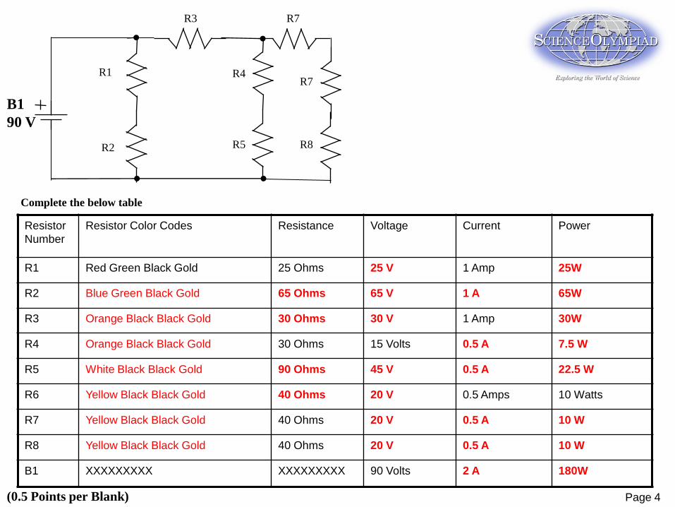
B1
90 V
R1 R4
R2
R3
R5
R7
R7
R8
Resistor
Number
Resistor Color Codes Resistance Voltage Current Power
R1 Red Green Black Gold 25 Ohms 25 V 1 Amp 25W
R2 Blue Green Black Gold 65 Ohms 65 V 1 A 65W
R3 Orange Black Black Gold 30 Ohms 30 V 1 Amp 30W
R4 Orange Black Black Gold 30 Ohms 15 Volts 0.5 A 7.5 W
R5 White Black Black Gold 90 Ohms 45 V 0.5 A 22.5 W
R6 Yellow Black Black Gold 40 Ohms 20 V 0.5 Amps 10 Watts
R7 Yellow Black Black Gold 40 Ohms 20 V 0.5 A 10 W
R8 Yellow Black Black Gold 40 Ohms 20 V 0.5 A 10 W
B1 XXXXXXXXX XXXXXXXXX 90 Volts 2 A 180W
Complete the below table
(0.5 Points per Blank) Page 4

Div. C Topics • DC circuit analysis practice
– Meter Usage • How do meters work
– Color Codes – Wheatstone Bridges
10

60A
Use Norton’s theorem to give the current through RA for the different
resistor values of RA
20 Ω
100 Ω 100 Ω
50 Ω 150 Ω
RA
RA Value Current
20 Ω 20 A
50 Ω 15 A
100 Ω 10.5
150 Ω 4.84
(10 Points) Page 7
20 Ω
100 Ω 100 Ω
50 Ω 150 Ω
VA VB
V1
Req = 20 + 1/ (1/(100+50)+1/(100+150)) = 113.7 Ohms
Vin = 6825V
V1 = Vin – 60 * 20 = 6705V
VA = V1*50/ 150 = 2235V
VB = V1 * 150/250 = 4203V
Voc = VB – VA = 1788V
20 Ω
100 Ω 100 Ω
50 Ω 150 Ω
V1 V VOC
ISC
Req = 20 + 50+ 1/(1/50+1/150) = 107 Ohms
Vin = 6450V
V2 = Vin *37.5/107.5 = 2250
V1 = Vin -120 = 6330 V
ISC = (V1-V2)/100 – V2/150 = 40.8 A – 15A = 25.8A
Rth = Voc/ISC = 69.3 Ohms
I = ISC * 69.3/(69.3+ RA) =
V2
69.3 Ω

Measure Voltage
Voltage is measured across a component.
Otherwise known as a voltage drop across the
component. The meter is connected in parallel
with the component to be measured.
Measure Current
Current is measured as a flow through a
component. In order to measure current through a
component, you will have to disconnect the circuit
and hook the meter in series with the component
to measure the current through.
Watch for Short Circuit
Measure Resistance
Resistance is measured across a component.
The meter is connected in parallel with the
component to be measured. In order to accurately
measure the resistance, you should disconnect
other components to prevent them from interfering
with your reading.
+
V1
-
+
Vin
-
R1 R2
+
I1
-
+
Vin
-
R1 R2
X
+
R
1
-
+
Vin
-
R1 R2
X
Using Meters

Find The problems with the Circuit
The circuit in this station was to be built per the below schematic, but, the circuit was built
incorrectly.
Measure and calculate the circuit voltages.
Use a comparison between the measured values and the calculated values to determine
which component or components of the circuit has been built incorrectly.
(25 Points)
X
X

Div. C Topics
• Intermediate DC circuits concepts, definitions and principles (including diodes and capacitors) – SI Units and derived units – Capacitance and RC Circuits – Ideal Diodes – Electron current – Digital Logic
14

Initially, Switch A is shorted, Switch B is open and there is no
charge on the capacitors. At time T = 0, Switch A opens. Next
at Time T= 1 second, Switch B closes. Finally at time T = 2
seconds Switch A closes.
Make a plot of the voltage on C1 and C2 over time indicating
the voltage of the capacitors just before and just after each
switch change.
Calculate the capacitor charging or discharging constant for
each of the conditions.
A
B R1
18KΩ B1
15V
B2
15V
C1
R2
18KΩ C1
10mF C2
5mF
Page 8
At T=0, C1, and C2 are in parallel, final target voltage is 30
Volts; time constant is 15mF * 18k = 270 s.
VC1, C2 = (V-Vi)* ( 1-e –t/tc) + Vi
At T = 1; Vi =0, tc = 270 s, V = 30
VC1, C2 = (30)* (1- e –1/270) + 0 = 0.11 V
Between t=1 and t = 2; Vi = 0.11V; V = 15 V; tc = 270 s; t = 1
VC1, C2 = (15-0.11)* (1- e –1/270) + .11 = 0.16 V
At t=2; C1 is shorted; charge stays on C2 because of the
diode
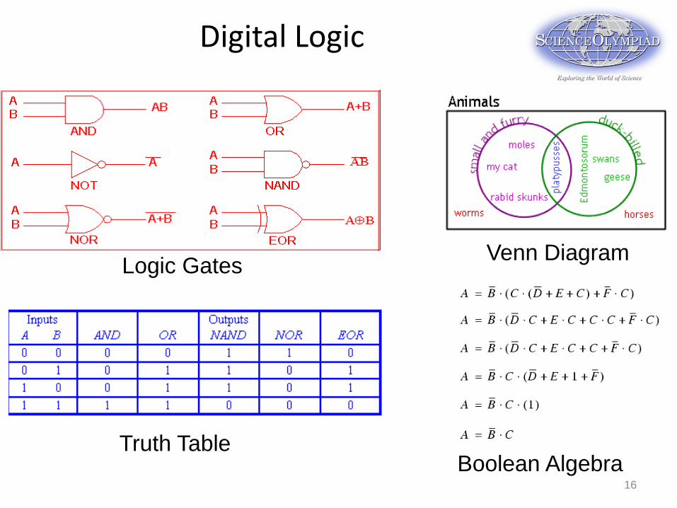
Digital Logic
16
Truth Table
Logic Gates Venn Diagram
Boolean Algebra

Suggested References
• Websites: • Soinc.org Shock Value / Circuit Lab Event pages • Scioly.org student forums / wiki / test exchange • Wikipedia (Electrical Circuit, Magnetism, etc.) • Ibiblio (Lessons in Electric Circuits, Volumes I,V and VI) • Youtube (Intro to electricity, Principles of Electricity) • http://phet.colorado.edu/en/simulation/circuit-construction-kit-dc • http://www.khanacademy.org/#Physics
• Books: • Science / Physics textbooks – most have chapters on this material • Electric Circuits, James W. Nilsson
17

Hands On / Fun Stuff • Kits and parts
– www.Sparkfun.com electronics kits, books
– http://www.elenco.com/ electronics kits
– http://www.kelvin.com/ Parts and kits – many subjects
• YouTube 2000 V demonstration – http://www.youtube.com/watch?v=8hwLHdBTQ7s&feature=youtube_
gdata_player
18


![Region 7 Jan 9, 2014 Shock Value - macombso.orgmacombso.org/images/mssodocs/resources/Shock Value Extravaganza... · Region 7 Jan 9, 2014 Shock Value ... Alexander Graham Bell[46]](https://img.pdfslide.net/doc/110x75/5aa1e6197f8b9a436d8c3edd/region-7-jan-9-2014-shock-value-value-extravaganzaregion-7-jan-9-2014-shock.jpg)