Embed Size (px)
Citation preview
Submitted to: Submitted by: Environment Bureau of Land Management AECOM Carlsbad Field Office Fort Collins, CO Eddy County, NM July 2010
Regional Geology; Geology and Minerals Issues Related to the Proposed HB In-Situ Solution Mine Project
Submitted to: Submitted by: Bureau of Land Management AECOM Carlsbad Field Office Fort Collins, CO Eddy County, NM July 2010
Environment
Regional Geology; Geology and Minerals Issues Related to the Proposed HB In-Situ Solution Mine Project
_________________________________ Prepared By: Bill Berg
_________________________________ Reviewed By: Ellen Dietrich
AECOM i
Contents
1.0 ................................................................................................................................................ 1-1 Introduction
1.1 Purpose of Report .......................................................................................................................... 1-1
1.2 Scope of Investigation .................................................................................................................... 1-1
2.0 Environmental Setting ............................................................................................................................... 2-1
2.1 Project Location and Climate ......................................................................................................... 2-1
2.2 Physiography and Topography ..................................................................................................... 2-1
3.0 Regional Geology ...................................................................................................................................... 3-1
3.1 Delaware Basin .............................................................................................................................. 3-1
3.2 Stratigraphy .................................................................................................................................... 3-3
3.3 Karst and Caves ............................................................................................................................. 3-6
4.0 Project Area Geology ................................................................................................................................ 4-1
4.1 Stratigraphy .................................................................................................................................... 4-1 4.1.1 Permian Rocks ................................................................................................................ 4-1 4.1.2 Triassic, Tertiary, and Quaternary Deposits .................................................................. 4-5
4.2 Structure ......................................................................................................................................... 4-5
5.0 Mineral Resources ..................................................................................................................................... 5-1
5.1 Potash Mining................................................................................................................................. 5-1
5.2 Oil and Gas Production .................................................................................................................. 5-2
5.3 Conflicts Between Potash Mining and Oil and Gas ...................................................................... 5-4
5.4 Other Minerals ................................................................................................................................ 5-7
6.0 Environmental Geology Conditions in the Project Area ...................................................................... 6-1
6.1 Karst ............................................................................................................................................... 6-1
6.2 Anthropogenic Subsidence ............................................................................................................ 6-2 6.2.1 General Principles of Mining Subsidence ...................................................................... 6-3 6.2.2 Mining Subsidence in the Project Area .......................................................................... 6-6 6.2.3 Subsidence Due to Brine Mining and Oil and Gas Activities ....................................... 6-16
7.0 Summary and Conclusions ...................................................................................................................... 7-1
7.1 Subsidence and Potash Mining ..................................................................................................... 7-1
7.2 Oil and Gas Production and Proposed Solution Mining ............................................................... 7-2
Regional Geology and Issues Report; HB In-Situ Solution Mine Project July 2010
AECOM ii
7.3 Recommendations ......................................................................................................................... 7-3 7.3.1 Recommendations Concerning Solution Potash Mining ............................................... 7-3 7.3.2 Recommendations Concerning Oil and Gas Activities .................................................. 7-4
8.0 References .................................................................................................................................................. 8-1
9.0 Glossary ...................................................................................................................................................... 9-1
Regional Geology and Issues Report; HB In-Situ Solution Mine Project July 2010
AECOM
Regional Geology and Issues Report; HB In-Situ Solution Mine Project July 2010
iii
List of Tables
Table 3-1 .................................................................... 3-4 Delaware Basin Generalized Stratigraphic Column
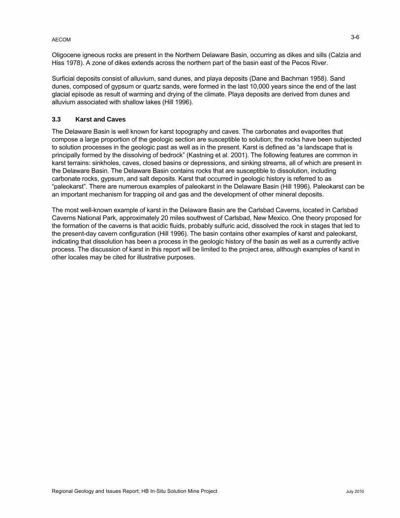
Table 3-2 Upper Guadalupian-Ochoan Formations in Project Area ........................................................... 3-5
Table 6-1 Subsidence Monitoring Transects ............................................................................................. 6-11
Table 6-2 Damage in Relation to Intensity of Ground Strain ..................................................................... 6-13
Table 6-3 Types and Causes of Pipe Fracture .......................................................................................... 6-16
Table 6-4 Barber Field Area Wells ............................................................................................................. 6-21
Table 6-5 Getty Field Area Wells ................................................................................................................ 6-24
List of Figures
Figure 2-1 .................................................................................................................... 2-2 Project Location Map
Figure 2-2 Pecos Valley and Adjacent Physiographic Sections ................................................................... 2-3
Figure 3-1 Map of Major Structural Elements ................................................................................................ 3-1
Figure 3-2 Structure Contour Map and General East-West Cross Section of the Delaware Basin ............ 3-2
Figure 3-3 Stratigraphic Relationship between Upper Guadalupian-Ochoan Series .................................. 3-5
Figure 4-1 Stratigraphic Column for the Project Area ................................................................................... 4-3
Figure 4-2 Geologic Map of the Project Area ................................................................................................ 4-4
Figure 5-1 Plan View Example of Room-and-Pillar, HB South Mine ............................................................ 5-2
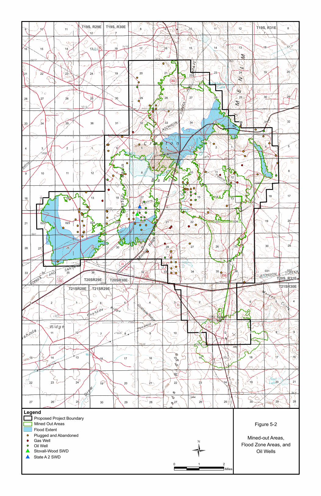
Figure 5-2 Project Area Map Showing Outlines of Mined Areas and Oil and Gas Wells ............................ 5-3
Figure 5-3 Structure Contour Map Base of Salado ....................................................................................... 5-5
Figure 5-4 Map of the Potash Area ................................................................................................................ 5-6
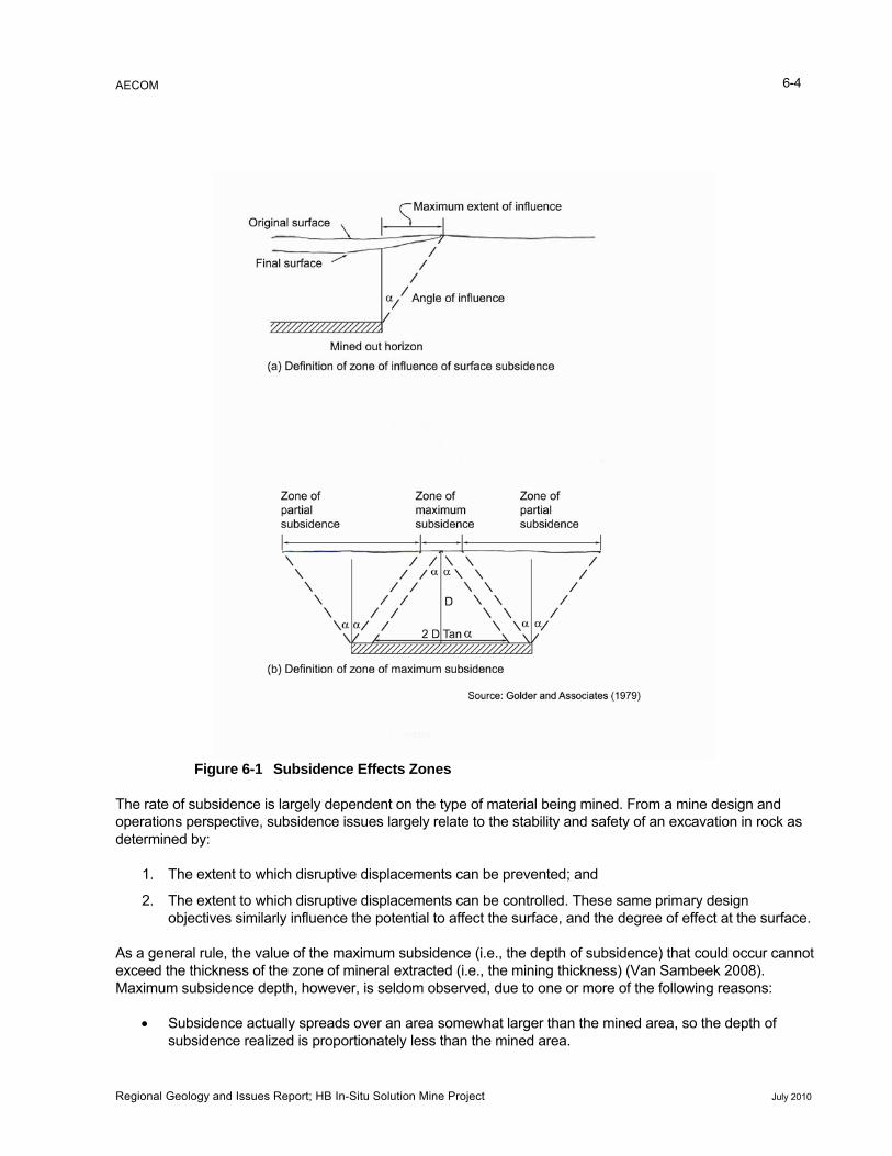
Figure 6-1 Subsidence Effects Zones ........................................................................................................... 6-4
Figure 6-2 Photo of Surface Tension Cracks ................................................................................................ 6-8
Figure 6-3 Representative Potential Subsidence Cross Section ................................................................ 6-11
Figure 6-4 Subsidence Monitoring Program................................................................................................ 6-12
Figure 6-5 Brine Mining Well Cavern Configuration .................................................................................... 6-17
Figure 6-6 Location Map for the Wink Sinks ............................................................................................... 6-19
Figure 6-7 Development of the Wink Sink ................................................................................................... 6-20
Figure 6-8 Typical Oil Well Construction in Project Area Circa 1920s to 1940s ........................................ 6-26
AECOM AA-1
List of Acronyms
°F degrees Fahrenheit
bgs below ground surface
BLM Bureau of Land Management
KCl Potassium chloride
NaCl Sodium chloride
OCD Oil Conservation Division
PCA Potash Corporation of America
SWD Salt water disposal
USGS United States Geological Survey
WIPP Waste Isolation Pilot Plant
U.S. United States
USP United States Potash
PVC polyvinyl chloride
Regional Geology and Issues Report; HB In-Situ Solution Mine Project July 2010
AECOM 1-1
1.0 Introduction
1.1 Purpose of Report
This report provides a review of environmental geology factors involved in the proposed in-situ mining of potash in Eddy County, New Mexico. The geological assessment will address potential impacts on the existing surface infrastructure including oil and gas wells, pipelines, power lines, roads, and other surface features resulting from subsidence or other subsurface deflections that may result from implementation of the proposed in-situ project submitted by Intrepid Potash, Inc. In addition to potential subsidence from solution mining, there are other concerns and hazards related to the presence of abandoned and active oil wells that penetrate the potash mining zone. The report provides a description of the regional and project area geology, mineral resources, and conditions relating to potential geologic and environmental hazards.
1.2 Scope of Investigation
The environmental geology assessment is intended to provide information on the potential effects of subsidence and as guidance for analyzing alternatives to the proposed in-situ solution mining. The Delaware Basin in which the project is located has extensive deposits of evaporite minerals (salts of various compositions) that are readily dissolved by unsaturated water solutions. When the evaporite deposits are dissolved, voids are created that can migrate to the surface, resulting in topographic and subsurface features (e.g., sinkholes, broad depressions, fissures, and caves) referred to as evaporite-karst (Johnson 2005). Dissolution of evaporite minerals can be caused by natural conditions or by human activities (e.g., mining, oilfield operations, improperly located water storage reservoirs). Subsidence resulting from dissolution of evaporite rocks can have negative impacts on structures, aquifers, surface water flow, wells, and livestock. The proposed project involves the solution of evaporite deposits to recover potassium-rich minerals. Solution mining may result in a small amount of surface subsidence, causing the indirect effects of subsidence such as surface cracks that divert runoff into the subsurface. Runoff diverted into the surface cracks may cause dissolution of highly soluble rocks and may result in overburden collapse that propagates to the surface, thereby damaging surface and subsurface resources.
Oil and gas exploration and production has taken place in the potash mining area since the 1920s. The potash bearing zones were discovered as a result of oil and gas exploratory drilling (Davis 2009). As a precaution, the potash mining companies reportedly left protection pillars around the boreholes (Intrepid Potash/Shaw 2008a). Well casing corrosion is a common problem in the Delaware Basin, caused by contact with the brine fluids being withdrawn or injected depending on the purpose of the well (Powers 2003). There are documented cases where escape of unsaturated brines and dissolution of salt formations has caused catastrophic collapse to the surface, not only in the Delaware Basin, but in other basins having substantial thicknesses of salt layers and numerous wells penetrating the salt for the purpose of fluid withdrawal. There are concerns that 70 years of oil production through the layers proposed for potash solution mining have created conditions that have not yet manifested themselves on the surface that could create hazards, not only due to subsidence, but to the efficiency and safety of the proposed potash mining operations.
This investigation and report will attempt to summarize the issues and concerns identified above based on existing data provided by Intrepid Potash, its consultant, Shaw Environmental and Infrastructure, and published reports or other information available in the public domain.
Regional Geology and Issues Report; HB In-Situ Solution Mine Project July 2010
AECOM 2-1
2.0 Environmental Setting
2.1 Project Location and Climate
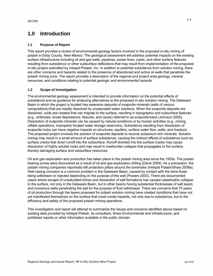
The proposed HB In-Situ Solution Mine Project is located about 20 miles northeast of Carlsbad, in Eddy County, New Mexico (Figure 2-1). The project area encompasses 38,453 acres and project elements are located north and south of United States (U.S.) Highway 62/180.
The area is semi-arid with an average rainfall of about 13.3 inches of precipitation per year (World Climate 2009). Most of the precipitation falls as rain from summer thunderstorms. The area experiences hot, sunny summers and mild winters with an average maximum temperature of 94.5 degrees Fahrenheit (°F) in July and an average minimum temperature of 26.6°F in January.
The primary industries in the project area consist of livestock grazing, potash mining, and oil and natural gas production. Of note is the Waste Isolation Pilot Project, located about 12 miles southeast of the project area. The Waste Isolation Pilot Project is actively storing low-level radioactive waste in a salt formation more than 2,000 feet below the ground surface (Rempe et al. 1999).
2.2 Physiography and Topography
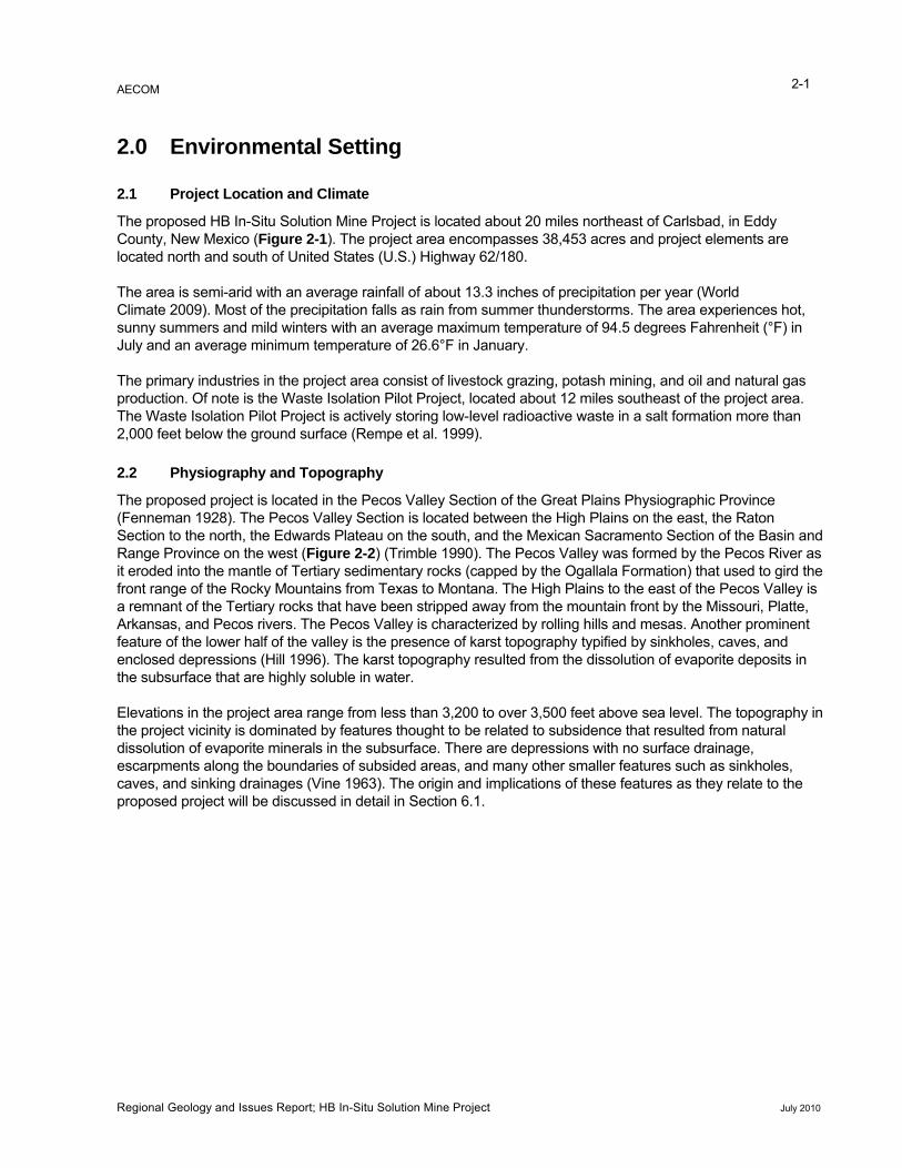
The proposed project is located in the Pecos Valley Section of the Great Plains Physiographic Province (Fenneman 1928). The Pecos Valley Section is located between the High Plains on the east, the Raton Section to the north, the Edwards Plateau on the south, and the Mexican Sacramento Section of the Basin and Range Province on the west (Figure 2-2) (Trimble 1990). The Pecos Valley was formed by the Pecos River as it eroded into the mantle of Tertiary sedimentary rocks (capped by the Ogallala Formation) that used to gird the front range of the Rocky Mountains from Texas to Montana. The High Plains to the east of the Pecos Valley is a remnant of the Tertiary rocks that have been stripped away from the mountain front by the Missouri, Platte, Arkansas, and Pecos rivers. The Pecos Valley is characterized by rolling hills and mesas. Another prominent feature of the lower half of the valley is the presence of karst topography typified by sinkholes, caves, and enclosed depressions (Hill 1996). The karst topography resulted from the dissolution of evaporite deposits in the subsurface that are highly soluble in water.
Elevations in the project area range from less than 3,200 to over 3,500 feet above sea level. The topography in the project vicinity is dominated by features thought to be related to subsidence that resulted from natural dissolution of evaporite minerals in the subsurface. There are depressions with no surface drainage, escarpments along the boundaries of subsided areas, and many other smaller features such as sinkholes, caves, and sinking drainages (Vine 1963). The origin and implications of these features as they relate to the proposed project will be discussed in detail in Section 6.1.
Regional Geology and Issues Report; HB In-Situ Solution Mine Project July 2010
Carlsbad
Carlsbad
Artesia
EddyCounty
LeaCounty
285
82
62
285
180
28562
285
360
31
529
524
216
249
176
357
35531
1st
Legend
0 2.5 5Miles
Figure 2-1
Project LocationWIPP Site
Proposed Project AreaMine Site
NMCOUT
AZTXOK
ProjectLocation
El Paso
Jal Midland
HobbsArtesia
Roswell
Albuquerque
Amarillo
CO
NM TX
Carlsbad
SouthernRocky
Mountains
40
40
54
NM
84
20
HighPlains
PecosValley
MexicanHighland
Navajo
Datil
Raton
Sacramento
EdwardsPlateau
CANYON LANDS
NM
TX
CO
OK
UTAZ
KS
25 27
10
40
25550
180 62
666
285
70
60
380
64
84
54
6790
82
70
287550
64
67
285
70
60
64
285
380
85
64
385
54
60
64
62
Legend
0 25 50Miles
Figure 2-2
PhysiographicProvinces
WIPP SiteProposed Project Area
Town
Source: Fenneman (1928).
AECOM 3-1
3.0 Regional Geology
3.1 Delaware Basin
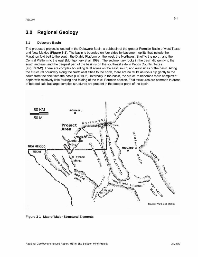
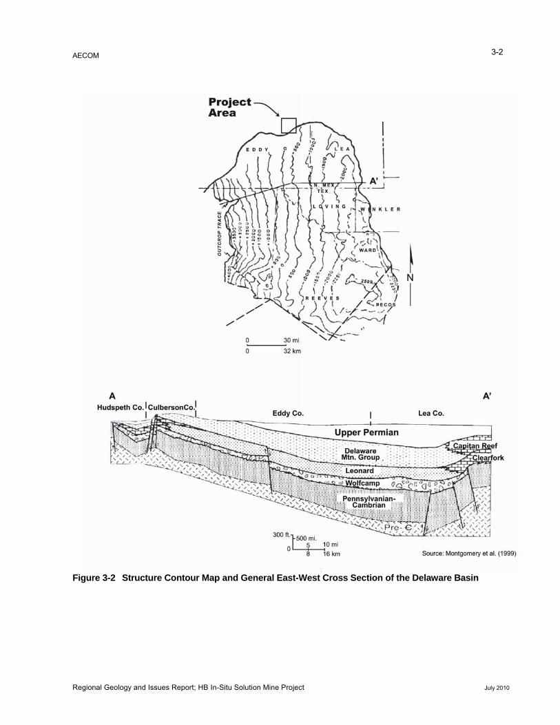
The proposed project is located in the Delaware Basin, a subbasin of the greater Permian Basin of west Texas and New Mexico (Figure 3-1). The basin is bounded on four sides by basement uplifts that include the Marathon fold belt to the south, the Diablo Platform on the west, the Northwest Shelf to the north, and the Central Platform to the east (Montgomery et al. 1999). The sedimentary rocks in the basin dip gently to the south and east and the deepest part of the basin is on the southeast side in Pecos County, Texas (Figure 3-2). There are complex bounding fault zones on the east, south, and west sides of the basin. Along the structural boundary along the Northwest Shelf to the north, there are no faults as rocks dip gently to the south from the shelf into the basin (Hill 1996). Internally in the basin, the structure becomes more complex at depth with relatively little faulting and folding of the thick Permian section. Fold structures are common in areas
Figure 3-1 Map of Major Structural Elements
of bedded salt, but large complex structures are present in the deeper parts of the basin.
Regional Geology and Issues Report; HB In-Situ Solution Mine Project July 2010
AECOM 3-2
Figure 3-2 Structure Contour Map and General East-West Cross Section of the Delaware Basin
Regional Geology and Issues Report; HB In-Situ Solution Mine Project July 2010
AECOM 3-3
3.2 Stratigraphy
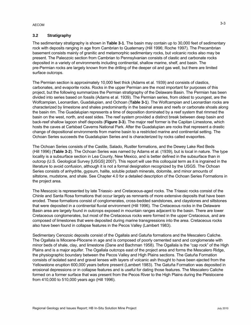
The sedimentary stratigraphy is shown in Table 3-1. The basin may contain up to 30,000 feet of sedimentary rock with deposits ranging in age from Cambrian to Quaternary (Hill 1996; Roche 1997). The Precambrian basement consists mainly of granitic and metamorphic sedimentary rocks, but volcanic rocks also may be present. The Paleozoic section from Cambrian to Pennsylvanian consists of clastic and carbonate rocks deposited in a variety of environments including continental, shallow marine, shelf, and basin. The pre-Permian rocks are largely known from the drilling of the deeper oil and gas well, but there are limited surface outcrops.
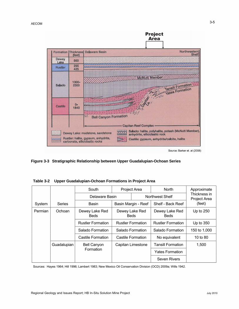
The Permian section is approximately 10,000 feet thick (Adams et al. 1939) and consists of clastics, carbonates, and evaporite rocks. Rocks in the upper Permian are the most important for purposes of this project, but the following summarizes the Permian stratigraphy of the Delaware Basin. The Permian has been divided into series based on fossils (Adams et al. 1939). The Permian series, from oldest to youngest, are the Wolfcampian, Leonardian, Guadalupian, and Ochoan (Table 3-1). The Wolfcampian and Leonardian rocks are characterized by limestone and shales predominantly in the basinal areas and reefs or carbonate shoals along the basin rim. The Guadalupian represents a time of deposition dominated by a reef system that rimmed the basin on the west, north, and east sides. The reef system provided a distinct break between deep basin and back-reef shallow lagoon shelf deposits (Figure 3-3). The major reef former is the Capitan Limestone, which hosts the caves at Carlsbad Caverns National Park. After the Guadalupian are rocks that represent a drastic change of depositional environments from marine basin to a restricted marine and continental setting. The Ochoan Series succeeds the Guadalupian Series and is characterized by rocks called evaporites.
The Ochoan Series consists of the Castile, Salado, Rustler formations, and the Dewey Lake Red Beds (Hill 1996) (Table 3-2). The Ochoan Series was named by Adams et al. (1939), but is local in nature. The type locality is a subsurface section in Lea County, New Mexico, and is better defined in the subsurface than in outcrop (U.S. Geological Survey [USGS] 2007). This report will use this colloquial term as it is ingrained in the literature to avoid confusion, although it is not a formal designation recognized by the USGS. The Ochoan Series consists of anhydrite, gypsum, halite, soluble potash minerals, dolomite, and minor amounts of siltstone, mudstone, and shale. See Chapter 4.0 for a detailed description of the Ochoan Series Formations in the project area.
The Mesozoic is represented by late Triassic- and Cretaceous-aged rocks. The Triassic rocks consist of the Chinle and Santa Rosa formations that occur largely as remnants of more extensive deposits that have been eroded. These formations consist of conglomerates, cross-bedded sandstones, and claystones and siltstones that were deposited in a continental fluvial environment (Hill 1996). The Cretaceous rocks in the Delaware Basin area are largely found in outcrops exposed in mountain ranges adjacent to the basin. There are lower Cretaceous conglomerates, but most of the Cretaceous rocks were formed in the upper Cretaceous, and are composed of limestones that were deposited during marine transgressions into the area. Cretaceous rocks also have been found in collapse features in the Pecos Valley (Lambert 1983).
Sedimentary Cenozoic deposits consist of the Ogallala and Gatuña formations and the Mescalero Caliche. The Ogallala is Miocene-Pliocene in age and is composed of poorly cemented sand and conglomerate with minor beds of shale, clay, and limestone (Dane and Bachman 1958). The Ogallala is the “cap rock” of the High Plains and is a major aquifer. The Ogallala outcrops east of the project area and forms the Mescalero Ridge, the physiographic boundary between the Pecos Valley and High Plains sections. The Gatuña Formation
the Yellowstone eruption 600,000 years before present (Lambert 1983). The Gatuña Formation was deposited in rosional depressions or in collapse features and is useful for dating those features. The Mescalero Caliche
formed on a former surface that was present from the Pecos River to the High Plains during the Pleistocene from 410,000 to 510,000 years ago (Hill 1996).
consists of isolated sand and gravel lenses with layers of volcanic ash thought to have been ejected from
e
Regional Geology and Issues Report; HB In-Situ Solution Mine Project July 2010
AECOM 3-4
Table 3-1 Delaware Basin Generalized Stratigraphic Column
Era System/ Period
Series/ Epoch Time (MY) Series/Group/Formation
Cen
ozoi
c Quaternary
Holocene 0.01 Sand and Gravel/Cave Deposits
Pleistocene 2 Gatuña Formation/Mescalero
Caliche Pliocene 6 Ogallala Formation Miocene 25 Absent
Tertiary Oligocene 35 Volcanic intrusive and extrusives Eocene 52 Absent Paleocene 65
Mes
ozoi
c
Cretaceous Upper Gulfian Series Lower 136 Comanchean Series
Jurassic Upper Absent Lower 190
Triassic Upper Chinle Group Middle Santa Rosa Lower 235
Pale
ozoi
c
Permian
Upper
Ochoan Series 250 Guadalupian Series 260
Middle Leonardian Series 270
Lower Wolfcampian Series 285
Pennsylvanian
Upper
Cisco/Gaptank
Middle Strawn 300
Lower Atoka 320 Morrow
Mississippian
Upper Barnett Shale
Middle
Mississippian Limestone 330
Lower 345
Devonian
Upper Woodford Shale 370 Middle 380 Absent
Lower Thirtyone Formation 390 400
Silurian Upper 410 Absent
Lower Wristen Formation 420 Fusselman Dolomite
Ordovician
Upper 455 Montoya Group Middle 475 Simpson Group Lower 495 Ellenburger Group
Cambian Upper Bliss Sandstone Lower 500 Absent
Proterozoic Precambian >570 Precambrian Source: Modified from Hill (1996).
Regional Geology and Issues Report; HB In-Situ Solution Mine Project July 2010
AECOM 3-5
Figure 3-3 Stratigraphic Relationship bet lupian-Ochoa
Table 3-2 Upper Guadalupian-Ochoan ions in ject Area
System Series
h Project a North Approximate ickness in
Project Area (feet)
ween Upper Guada n Series
Format Pro
Sout AreThDelaware Basin Northwest Shelf
Basin Basin Marg Shelf - Back Reef in - Reef
Permian Ochoan Dewey Lake Red ds
ewey LBe
Dewey Lake Be
Up to 250 Be
D ake Red ds
Red ds
Rustler Formatio n Ru Up to 350 n Rustler Formatio stler Formation
Salado Formatio alado Formation Salado 150 to 1,000 n S Formation
Castile Formatio Formation 10 to 80 n Castile No equivalent
Guadalupian Bell Canyon tion
Tan 1,500 Forma
Capitan Limestone sill Formation
Yates Formation
Seven Rivers
Sources: Hayes 1964; Hill 1996 83; New il Conserva n Division (OCD) ; Lambert 19 Mexico O tio 2009a; Wills 1942.
Regional Geology and Issues Report; HB In-Situ Solution Mine Project July 2010
AECOM
Regional Geology and Issues Report; HB In-Situ Solution Mine Project July 2010
3-6
Oligocene igneous rocks are present in the Northern Delaware Basin, occurring as dikes and sills (Calzia and Hiss 1978). A zone of dikes extends across the northern part of the basin east of the Pecos River.
Surficial deposits consist of alluvium, sand dunes, and playa deposits (Dane and Bachman 1958). Sand dunes, composed of gypsum or quartz sands, were formed in the last 10,000 years since the end of the last glacial episode as result of warming and drying of the climate. Playa deposits are derived from dunes and alluvium associated with shallow lakes (Hill 1996).
3.3 Karst and Caves
The Delaware Basin is well known for karst topography and caves. The carbonates and evaporites that compose a large proportion of the geologic section are susceptible to solution; the rocks have been subjected to solution processes in the geologic past as well as in the present. Karst is defined as “a landscape that is principally formed by the dissolving of bedrock” (Kastning et al. 2001). The following features are common in karst terrains: sinkholes, caves, closed basins or depressions, and sinking streams, all of which are present in the Delaware Basin. The Delaware Basin contains rocks that are susceptible to dissolution, including carbonate rocks, gypsum, and salt deposits. Karst that occurred in geologic history is referred to as “paleokarst”. There are numerous examples of paleokarst in the Delaware Basin (Hill 1996). Paleokarst can be an important mechanism for trapping oil and gas and the development of other mineral deposits.
The most well-known example of karst in the Delaware Basin are the Carlsbad Caverns, located in Carlsbad Caverns National Park, approximately 20 miles southwest of Carlsbad, New Mexico. One theory proposed for the formation of the caverns is that acidic fluids, probably sulfuric acid, dissolved the rock in stages that led to the present-day cavern configuration (Hill 1996). The basin contains other examples of karst and paleokarst, indicating that dissolution has been a process in the geologic history of the basin as well as a currently active process. The discussion of karst in this report will be limited to the project area, although examples of karst in other locales may be cited for illustrative purposes.

AECOM 4-1
4.0 Project Area Geology
4.1 Stratigraphy
The important units in the project area consist of Permian rocks of the Guadalupian and Ochoan Series, whare described below. The units are categorized by t
ich heir locations relative to the Capitan reef, which marks the
transition from shelf (back reef) to reef (basin margin) to basin. The stratigraphic relationships are shown in diagram is shown in Table 3-2. The project area lies along the basin margin-reef
e, Bell Canyon Formation, and the upper Artesia Group. These units are time-equivalent: the Capitan Limestone is
Figure 3-3 and a correlationarea, defined by the Capitan Limestone.
In addition to the upper Permian rocks, there are surficial exposures of Triassic, Tertiary, and Quaternary deposits in the project area that also are described below.
4.1.1 Permian Rocks
4.1.1.1 Guadalupian Series
Rock units in the Guadalupian Series of interest in the project area consist of the Capitan Limeston
the basin margin reef-derived unit, the Bell Canyon Formation was deposited in the basin, and the upper Artesia Group consists of back reef and shelf deposits.
Capitan Limestone
At the beginning of Permian time, the configuration of the Delaware Basin as we know it began to take shape (Hayes 1964). In late Guadalupian time, conditions were favorable for reef growth at the basin margin so the Capitan Limestone reef deposits built upward and toward the basin.
he Capitan Limestone is composed of massive reef material and associated reef talus zones (Hayes 1964). The reef material is thought to have been derived from organisms such as algae and sponges, but diagenetic changes and recrystallization have obscured much of the fossils. Because the massive reef building facies built upward and toward the basin, it developed on top of its own talus deposits. The talus resulted from erosion of the reef material at the water surface to wave base. Porosity in the Capitan massive reef facies is generally low because of cements, but there are occasional vugs and cavernous porosity (Hill 1996).
Bell Canyon Formation
T
The Bell Canyon Formation is the uppermost formation of the Delaware Mountain Group, a designation for the basinal formations of the Guadalupian Series. It is equivalent to the Capitan Limestone and is generally composed of turbidite sandstones that were deposited in a deep water setting (Berg 1979). Carbonate rocks also are present in the Bell Canyon Formation in areas close to the reef and Bell Canyon sediments interfinger with the talus slope of the Capitan reef. The Delaware Basin was a “sediment starved” basin, but during times of sea level drop, clastic sediments were moved to the shelf margin and eventually deposited in the basin by turbidity flows. The turbidite flows deposited sand in elongate sinuous channels with sediment transport from generally north to south and southwest across the shelf and into the basin (Payne 1976).
Artesia Group
The formations in the upper part of the Artesia Group are composed of rocks that are the shelf time-equivalent units to the Capitan Limestone. The formations are the Tansill, Yates, and Seven Rivers. The Seven Rivers Formation, time-equivalent to the lower Capitan Limestone, is largely composed of dolomite in areas close to the reef, but transitions into gypsum or anhydrite facies toward the shelf. The Yates is equivalent to the middle Capitan Limestone, consisting of up to two-thirds sandstone with intervening beds of dolomite (Lambert 1983). The Yates grades to evaporites in the direction of the shelf. The Tansill Formation is equivalent to the upper Capitan Limestone and is composed of dolomite in the basin margin-reef areas, transitioning into evaporites towards the shelf.
Regional Geology and Issues Report; HB In-Situ Solution Mine Project July 2010
AECOM 4-2
4.1.1.2 Ochoan Series
Castile Formation
The Castile Formationconditions favorable to
marks the end of open marine conditions in the Delaware Basin and the onset of evaporite deposition. The Castile is mainly composed of anhydrite, but contains three
mbination o ting factors were involved including tectonic
uplift, paleogeography, and hot, dry climate.
halite beds that range from 100 to 300 feet thick (Hill 1996). Minor limestone beds are present, but thin towards the shelf. Although the Castile can be up to 1,600 feet thick, in the project area it is a thin zone that overlies the Capitan reef and ranges from 10 to 80 feet thick (Wills 1942). Theories abound about the mechanism for the deposition of Ochoan evaporites and whether they are from deep or shallow water deposits(Hill 1996). However, it is certain that a co f contribu
Salado Formation
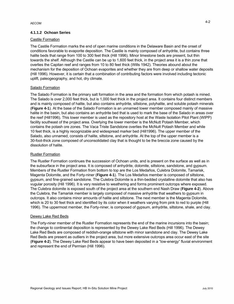
The Salado Formation is the primary salt formation in the area and the formation from which potash is mined. eet thick, but is 1,000 feet thick in the project area. It contains four distinct members
te, but also contains anhydrite, siltstone, polyhalite, and soluble potash minerals Salado Formation is an unnamed lower member composed mainly of massive
over )
ne overlies the McNutt Potash Member and while 10 feet thick, is a highly recognizable and widespread marker bed (Hill1996). The upper member of the
ed, consists of halite, siltstone, and anhydrite. At the top of the upper member is a
The Salado is over 2,000 fand is mainly composed of hali(Figure 4-1). At the base of thehalite in the basin, but also contains an anhydrite bed that is used to mark the base of the Salado in areas the reef (Hill1996). This lower member is used as the repository host at the Waste Isolation Pilot Plant (WIPPfacility southeast of the project area. Overlying the lower member is the McNutt Potash Member, which contains the potash ore zones. The Vaca Triste Sandsto
Salado, also unnam30-foot-thick zone composed of unconsolidated clay that is thought to be the breccia zone caused by the dissolution of halite.
Rustler Formation
The Rustler Formation continues the succession of Ochoan units, and is present on the surface as well as in the subsurface in the project area. It is composed of anhydrite, dolomite, siltstone, sandstone, and gypsum. Members of the Rustler Formation from bottom to top are the Los Medaños, Culebra Dolomite, Tamarisk, Magenta Dolomite, and the Forty-niner (Figure 4-1). The Los Medaños member is composed of siltstonegypsum, and fine-grained sandstone. The Culebra Dolomite is a thin-bedded crystalline dolomite that also havugular porosity (Hill 1996). It is very resistive to weathering and forms prominent outcrops where exp
, s
osed. The Culebra dolomite is exposed south of the project area at the southern end Nash Draw (Figure 4-2). Above
k member is largely composed of massive anhydrite that weathers to gypsum in
the Culebra, the Tamarisoutcrops. It also contains minor amounts of halite and siltstone. The next member is the Magenta Dolomite, which is 20 to 30 feet thick and identified by its color when it weathers varying from pink to red to purple (Hill 1996). The uppermost member, the Forty-niner, is composed of gypsum, anhydrite, siltstone, shale, and clay.
Dewey Lake Red Beds
The Forty-niner member of the Rustler Formation represents the end of the marine incursions into the basin; the change to continental deposition is represented by the Dewey Lake Red Beds (Hill 1996). The Dewey Lake Red Beds are composed of reddish-orange siltstone with minor sandstone and clay. The Dewey Lake Red Beds are present as outliers in the project area, but more extensive outcrops area occur east of the site
e Dewey Lake Red Beds appear to have been deposited in a “low-energy” fluvial environment (Figure 4-2). Thand represent the end of Permian (Hill 1996).
Regional Geology and Issues Report; HB In-Situ Solution Mine Project July 2010
AECOM 4-3
Figure 4-1 Stratigraphic Column for the Project Area
Regional Geology and Issues Report; HB In-Situ Solution Mine Project July 2010
Carlsbad
Eddy County Lea County
Pr
Pr
Pr
Pr
Pr
PrPr
PrPr
Pr
PrPr
Eddy County Lea County
62
285
285
285
360
31
176
524
216
128
Burton Flat
Nash Draw
Clayton Basin
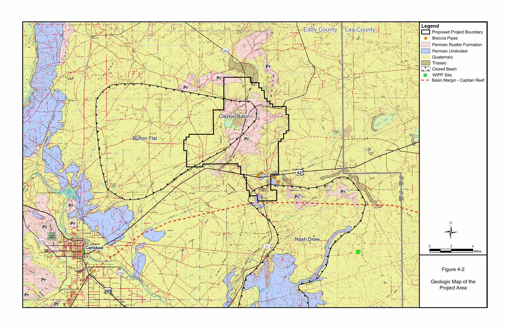
LegendProposed Project Boundary
Figure 4-2
Geologic Map of theProject Area
0 2 4Miles
Basin Margin - Capitan Reef
Breccia Pipes
WIPP Site
Permian Rustler Formation
QuaternaryTriassic
Permian Undivided
Closed Basin
AECOM
Regional Geology and Issues Report; HB In-Situ Solution Mine Project July 2010
4-5
.1.2 Triassic, Tertiary, and Quaternary Deposits
rmation are present in the project area. Undivided Triassic oject area are composed of maroon, red, and gray
andstone interbedded with red, sandy shale and purplish limestone. The Santa Rosa outcrops on the east the project area (Figure 4-2). The Dewey Lake Red Beds would likely be distinguished from the Santa
Rosa Formation because the top of the Dewey Lake is an erosion surface and the contact with younger rocks would be an angular unconformity (Lambert 1983).
There are no sedimentary Tertiary deposits in the area; however, Tertiary (Oligocene) igneous dikes and sills are present in the project area (Calzia and Hiss 1978). The dikes have been reported in the potash mines and occur as parallel and nearly vertical, with widths up to 12 feet. The dikes appear to die out in the Ochoan rocks and do not appear on the surface. The igneous rocks also have been documented from boreholes.
The oldest Quaternary deposit is the Gatuña Formation, which is present in limited outcrops in the Nash Draw area (Vine 1963). The extent and occurrence of the Gatuña in the project area has not been determined.
The Mescalero Caliche was described by Vine (1963) as limestone that ranges from dense to travertine-like with intermixed sand grains. It has been mapped in the southern part of the project area near the proposed solar ponds and near Intrepid’s West Mine; however, the full extent of the unit over the entire area has not been mapped.
Recent geologic materials in the project area consist of layers of alluvium, windblown sand, and gypsite that cover most of the Permian rocks (Wills 1942). Where deep channels have been cut into the Permian bedrock, recent materials may attain a thickness of 500 feet. Windblown deposits are fairly extensive over the project area. Playa deposits are mapped at the south end of Nash Draw at Salt Lake (Laguna Grande de la Sal), but not in the project area (Vine 1963; Intrepid Potash/Shaw 2008a). The largest playa in this area is Salt Lake, south of Nash Draw.
4.2 Structure
The localized structure of the area is dominated by salt dissolution and flowage and is not related to tectonic stress. The regional dip is 90 to 100 feet per mile (1 degree) to the southeast (Intrepid Potash/Shaw 2008a). However, in the project vicinity, the dissolution of evaporite layers combined with the flowage of salt created a somewhat chaotic structure. Because of the plastic nature of salt, it responds to stress by flowing and this flowage results in deformation of adjacent strata. The dissolution of salt layers has had the effect of creating basins in which the strata bend downward into the depression against the regional dip. This is exhibited at Nash Draw where the structure on top of the Salado forms a closed depression and the rocks exposed on the surface have a chaotic, jumbled appearance. Other evidence of salt flowage and dissolution in the project vicinity includes localized steep dips and salt-cored anticlines.
4
Triassic-aged rocks thought to be Santa Rosa Forocks mapped by Dane and Bachman (1958) in the prsside of
AECOM 5-1
5.0 Mineral Resources
as organized by the Snowden McSweeney Company and was jointly owned by the Snowden McSweeney Company and the Pacific Coast Borax Company (Kern 1984).
er 1929 and the first shaft was completed in 1931. Potash production and commercial shipments began in 1931. By
en n
9). Potash production continues in the project vicinity with active mining at Intrepid’s West and East Mines and the Mosaic Mine, about 10 miles south of the project area. Although much of the high-grade
).
f
e are twelve ore zones present in the Salado Formation, eleven of which are located in the McNutt Potash zone with varying mineralogy and commercial viability (Cheeseman 1978). The ore zones
the deepest to the shallowest by the USGS, with the First Ore Zone being the deepest
ls
re riginally conducted by traditional room-and-
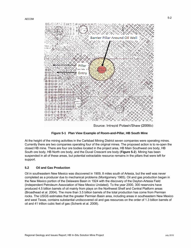
pillar methods using conventional mining techniques of drilling and blasting to extract the ore. Room-and-pillar mining is a method by which tabular-shaped or layered ore bodies are mined, leaving substantial reserves in the form of pillars for roof support (Figure 5-1) (American Geological Institute 1997).
Continuous mining technology was introduced into the mines, increasing extraction efficiency (Sisselman 1978), However, support pillars are still necessary features of this mining method. When mining around existing oil and gas wells, 100-foot diameter pillars are established around the well bore (Intrepid Potash/Shaw 2008a). The pillar sizes were increased when conditions warranted more support. Potash ore is moved from the working face and transported by a system of conveyor belts to the hoisting shaft. The ore is then hoisted from the mine level to the surface where it is sent to a refinery to remove the potash minerals from the ore. The major waste products from ore processing are sediment, salt, and other minerals that cannot be easily extracted (Barker et al. 2008). The salt and sediment are slurried to tailing piles, and waste brine solutions from the process are placed into evaporation ponds where additional recovery of waste water and salt minerals may occur.
5.1 Potash Mining
Potash was discovered in Eddy County in 1925 in a well that was being drilled for oil and gas by the Snowden McSweeney Company (Davis 2009). The discovery of high-grade potash resulted in the establishment of the American Potash Company in 1926. The company w
The company name, American Potash Company, was changed to United States Potash Company in 1929, soas not to confuse the company with the American Potash and Chemicals Company located at Searles Lake, California. The company began a potash exploration program in 1926, which located a sylvite bed of sufficient quantity to justify the sinking of a shaft and the building of a refinery. Shaft sinking began in Decemb
the mid-1930s, there were eleven companies exploring for potash in southeastern New Mexico (Barker et al. 2008).
The Potash Corporation of America (PCA) began mining operations in 1934 with peak production in 1966 of over 1 million tons of potash (Intrepid Potash/Shaw 2008a). The potash in southeastern New Mexico has bea major potash resource (Cheeseman 1978). The remaining potash reserves are estimated to be 500 milliotons (USGS 200
zones have been mined out, exploration for commercially viable deposits continues (Muller and Galyen 2009
The McNutt potash zone in the Salado Formation contains the potash minerals of interest to this project. It is named after V.H. McNutt who held the oil and gas lease where the potash was discovered in the well drilled bythe Snowden McSweeney Oil Company (Davis 2009). The potash zones present a complicated mineralogy opotash minerals. Ther
were numbered fromand the Twelveth Ore Zone being the shallowest. Mining has occurred in commercial quantities from First, Third, Fourth, Fifth, Seventh and Tenth Ore Zones. The First Ore Zone was the richest in terms of potassium content and has been extensively mined. The First Ore Zone is the zone proposed to be mined by this action and in the project area lies between 675 and 1,450 feet beneath the ground surface (Intrepid Potash/Shaw 2008a). The major commercial minerals in the ore are sylvite (KCl) and langbenite. Non-ore (gangue) minerainclude leonite, kainite, carnalite, polyhalite, kieserite, halite, and anhydrite. Potash has a variety of uses with the most common being a component of fertilizer.
The mines are accessed through shafts sunk from the to the ore level. Entries for access and ore haulage aextended from the shafts out to the mining areas. Mining was o
Regional Geology and Issues Report; HB In-Situ Solution Mine Project July 2010
AECOM 5-2
Figure 5-1 Plan View Example of Room-and-Pillar, HB South Mine
At the height of the mining activities in the Carlsbad Mining District seven companies were operating mines. Currently there are two companies operating four of the original mines. The proposed action is to re-open the closed HB mine. There are four ore bodies located in the project area, HB Main Southwest ore body, HB South ore body, HB North ore body, and the Duval Crescent ore body (Figure 5-2). Mining has been suspended in all of these areas, but potential extractable resource remains in the pillars that were left for support.
reservoirs have
5.2 Oil and Gas Production
Oil in southeastern New Mexico was discovered in 1909, 8 miles south of Artesia, but the well was never completed as a producer due to mechanical problems (Montgomery 1965). Oil and gas production began in the New Mexico portion of the Delaware Basin in 1924 with the discovery of the Dayton-Artesia Field (Independent Petroleum Association of New Mexico Undated). To the year 2000, 300 produced 4.5 billion barrels of oil mainly from plays on the Northwest Shelf and Central Platform areas (Broadhead et al. 2004). The more than 3.5 billion barrels of the total production has come from Permian rocks. The USGS estimates that the greater Permian Basin area, including areas in southeastern New Mexico and west Texas, contains substantial undiscovered oil and gas resources on the order of 1.3 billion barrels of oil and 41 trillion cubic feet of gas (Schenk et al. 2008).
Regional Geology and Issues Report; HB In-Situ Solution Mine Project July 2010
T20SR30ET21SR29E
T19S, R30E
T20SR29E
T19S, R29E
T21SR28E T21SR30ET20S, R31E
T19S, R31E
65 3 514 212 6
19
18
711
11
11
11
3 2
8
12
24
1
17
13
20
23
27
024 19
29 30
33
13
031
21
2
23 22
10
36
21
22
15
28
35
15
12
14
16
26
23
10
022 023 020
32
14
27
16 18
34
34
20
31
3332
8
14
25
13
2728
26
24
9
29
3
21 24
14
22
36
14
8
25
17 16
23 20
13
17
31
13
3634
15
25
12
10
24
5
14
27
34
9
23
17
22
26
35
26
35
15
15
30
35
6
77
18
30
019
4
31
18
30
19 19
18
3
6
19
18
7
17
20
29
32
5
8
17
20
29
032
22
15
10
4
30
11
29
1012
25 25
78
26
11
26
9
27
10
28
12
29
36
024
25
30
8
9
16
27
21
33
28
21
16
9
4
33
13
28
21
16
12
1
28
97
LegendProposed Project Boundary
Figure 5-2
Mined-out Areas,Flood Zone Areas, and
Oil Wells
0 1 2Miles
Flood ExtentMined Out Areas
Plugged and AbandonedGas WellOil WellStovall-Wood SWDState A 2 SWD
AECOM
Regional Geology and Issues Report; HB In-Situ Solution Mine Project July 2010
5-4
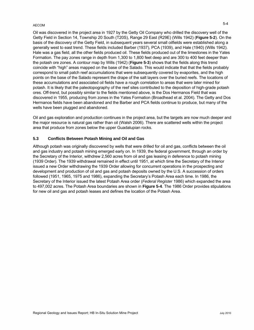
Oil was discovered in the project area in 1927 by the Getty Oil Company who drilled the discovery well of the Getty Field in Section 14, Township 20 South (T20S), Range 29 East (R29E) (Wills 1942) (Figure 5-2). On the basis of the discovery of the Getty Field, in subsequent years several small oilfields were established along a generally west to east trend. These fields included Barber (1937), PCA (1939), and Hale (1940) (Wills 1942). Hale was a gas field, all the other fields produced oil. These fields produced out of the limestones in the Yates Formation. The pay zones range in depth from 1,300 to 1,800 feet deep and are 300 to 400 feet deeper than the potash ore zones. A contour map by Wills (1942) (Figure 5-3) shows that the fields along this trend coincide with “high” areas mapped on the base of the Salado. This would indicate that that the fields probably correspond to small patch reef accumulations that were subsequently covered by evaporites, and the high points on the base of the Salado represent the drape of the salt layers over the buried reefs. The locations of these accumulations and associated oil fields have a rough correlation to areas that were later mined for potash. It is likely that the paleotopography of the reef sites contributed to the deposition of high-grade potash ores. Off-trend, but possibly similar to the fields mentioned above, is the Dos Hermanos Field that was discovered in 1955, producing from zones in the Yates Formation (Broadhead et al. 2004). The Getty and Dos Hermanos fields have been abandoned and the Barber and PCA fields continue to produce, but many of the wells have been plugged and abandoned.
Oil and gas exploration and production continues in the project area, but the targets are now much deeper and the major resource is natural gas rather than oil (Walsh 2006). There are scattered wells within the project area that produce from zones below the upper Guadalupian rocks.
5.3 Conflicts Between Potash Mining and Oil and Gas
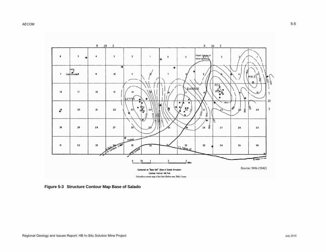
Although potash was originally discovered by wells that were drilled for oil and gas, conflicts between the oil and gas industry and potash mining emerged early on. In 1939, the federal government, through an order by the Secretary of the Interior, withdrew 2,560 acres from oil and gas leasing in deference to potash mining (1939 Order). The 1939 withdrawal remained in effect until 1951, at which time the Secretary of the Interior issued a new Order withdrawing the 1939 Order allowing for concurrent operations in the prospecting and development and production of oil and gas and potash deposits owned by the U.S. A succession of orders followed (1951, 1965, 1975 and 1986), expanding the Secretary’s Potash Area each time. In 1986, the Secretary of the Interior issued the latest Potash Area order (Federal Register 1986) which expanded the area to 497,002 acres. The Potash Area boundaries are shown in Figure 5-4. The 1986 Order provides stipulations for new oil and gas and potash leases and defines the location of the Potash Area.
AECOM 5-5
re ct to p B alad
Figu 5-3 Stru ure Con ur Ma ase of S o
Regional Geology and Issues Report; HB In-Situ Solution Mine Project July 2010
AECOM 5-6
Figure 5-4 Map of the Potash Area
Regional Geology and Issues Report; HB In-Situ Solution Mine Project July 2010
AECOM
Regional Geology and Issues Report; HB In-Situ Solution Mine Project July 2010
5-7
The New Mexico Oil Conservation Division (OCD) is a cooperating agency in the implementation of the Order and potash lessees in the potash enclave can protest drilling permit applications to the OCD. However, the BLM authorizing officer has the final authority on decisions for approving proposals for drilling.
Since 1955, the OCD issued a series of orders that have been amended over the years to specifically address how oil and gas operations are to be conducted in the potash enclave (OCD 2009a). The original OCD order was R-111-A and the current order is R-111-P. As noted in the most recent order issued in 1988, many revisions were necessary as a result of disputes between the potash and oil and gas industries and uncertainties resulting from boundary changes. A summary of the provisions in R-111-P are listed below.
Requirements for setting casing strings including surface, intermediate, salt section, and production.
Casing cementing and testing requirements.
Drilling fluid requirements for drilling the salt section.
Plugging and abandonment rules.
Designation of well locations.
Potash lease owners within 0.5 mile of a well can witness casing, cementing, and plugging operations.
Oil and gas operators may inspect mine workings.
Potash lease owners must annually submit mine surveys to OCD.
Oil and gas operators must submit certified directional surveys to OCD for each well drilled.
In 2004, the oil and gas production from the Potash Area was 27.3 billion cubic feet of gas and 4.7 million barrels of oil (Walsh 2006). The remaining oil and gas resource in the Potash Area is estimated to be 468 million barrels of oil and 5.5 trillion cubic feet of gas. A total of 1,291 wells have been drilled in the R-111-P area (Balch et al. 2009).
5.4 Other Minerals
Other minerals produced in Eddy County include sand and gravel, caliche, salt, and sulfur as a byproduct of natural gas production (USGS 2009). Salt formations are utilized by two methods:
1. Solution mining where a well is drilled into the salt formation and unsaturated water is pumped into the well to dissolve the salt. The saturated solution is extracted and used as make-up water for saturated drilling fluids for oil and gas well drilling. There are no brine extraction wells in the project area.
2. Mining salt that has precipitated in playas. Mining in this manner is typically accomplished with the use of scrapers.
AECOM 6-1
6.0 Environmental Geology Conditions in the Project Area
6.1 Karst
.5, karst is widespread in the Delaware Basin. Of particular concern is the presence n
ifested in a number of
karst
The expansion can result in buckling and deformation of adjacent rock layers and racking in the gypsum bed (Bachman 1983). The cracking and deformation of adjacent beds can allow fluids infiltrate into lower layers.
The Capitan reef contains cavernous areas in the subsurface and anomalously high porosity, indicating the presence of large vugs, “honeycomb” structure, and evidence of solution (Hill 1996). The Capitan Limestone does not outcrop in the project area, but is present in the subsurface. However, the formation of cavernous porosity may be relevant to the formation of karst features such as breccia pipes that are described below.
Sinkholes are very common in the Nash Draw and Burton Flat areas and are primarily developed in the gypsum that outcrops or is near the surface (Hill 1996). Sinkholes are small depressions in the earth’s surface that are the surface manifestation of rock dissolution that has taken place in the subsurface. Sinkholes are commonly small features, can be elliptical or circular, some with dimensions in the tens of meters (Baum et al. 2008).
An unusual feature in the project area is the presence of breccia pipes, which have been described in detail by Vine (1960). The pipes occur on the surface as circular domes, and are 1,200 to 1,500 feet in diameter and about 50 to 100 feet high (Vine 1960). The features are referred to as “breccia” pipes because drilling and exposures in the Intrepid West underground mine has shown the matrix of the pipes consists of tilted and erratic blocks of material derived from the Salado and Rustler formations (Snyder and Gard 1982). Another aspect of the pipes is the dome-like appearance on the surface. It is possible that at one time the surface expression of the pipes was a sinkhole-like depression, but lowering of the formations around the domes by a later stage of dissolution created the dome effect. The caliche layer on the domes dates the pipes to around 600,000 years before present. The breccia pipes are thought to have originated from solution and collapse of voids in the Capitan Limestone, but also could have resulted from the solution of salts or anhydrites higher in the section. One theory surmises that when dissolution caused breaching of the Capitan Limestone, the loss of support caused the layer above to eventually collapse. Artesian conditions in the Capitan Limestone forced unsaturated water upward, causing continual collapse that resulted in unsaturated water coming in contact with soluble salts (Davies 1983; Hill 1996). The dissolution of the evaporites caused additional collapse to occur.
Of the four documented breccia pipes, two are located in the project area, in the SW¼ of Section 35, T20N, R30E (Dome A) and in the NW¼ of Section 1 and the NE¼ of Section 2 in T21S, R29E (Dome B) (see Figure 4-2). Two other breccia pipes or domes are located on the east side of Intrepid’s West Mine in the SW¼ of Section 5, T21S, R30E.
Oil has been observed where mine workings have intercepted one of the pipes. Geochemical fingerprinting has shown the oil to be similar to oil from the Yates Formation that is produced in the Getty, Barber, PCA, and Dos Hermanos oil fields (Palacas et al. 1982). The presence of oil similar to Yates reservoirs supports the pipe formation theory described above because artesian water from the Capitan Limestone may have carried oil
As described in Section 3of evaporite karst. Because evaporite minerals are much more soluble than calcium carbonate, dissolution ofevaporites can occur rapidly compared to the dissolution of limestone. Most of the karst in the Delaware Basiis evaporite karst. On the north side of the basin within the project area, karst is manfeatures, some that can be identified on the surface and others hidden in the subsurface (Hill 1996). Some of the major features include cavernous or vuggy porosity, sinkholes, breccia pipes, blanket breccia zones, caves, karst valleys, and dissolution breccias. Breccia is a deposit consisting of fragmented rock materials thatresults from the collapse of underground voids as the result of the dissolution of evaporite layers. Other features can result from the property of anhydrite that causes it to expand in size when it becomes hydrated and turns to gypsum.cto
Regional Geology and Issues Report; HB In-Situ Solution Mine Project July 2010
AECOM 6-2
possible he Neil
ld, rise in water level from the oil zone at 1,647 to 1,650 feet to about 1,200 feet in 9 hours
formation is not provided in the description of well testing to determine whether the fluid was
, and rattlesnakes. A few caves have been nominated as “Significant
eccias or blanket-dissolution breccias occur where subsurface solutions have dissolved the
d
ent
area, but that controversy is not within the scope of this report. At the eastern edges of the basin t
ce
ly
from breached traps in the Yates Formation to higher levels. Another piece of evidence supporting themigration of fluids from deeper zones comes from an exploratory oil well that was drilled in 1938. TWills State 2-A well in the SE¼ NE¼ Section 19, T20S, R30E, located on the west flank of the Barber Fiehad a recorded(OCD 2009a). Inallowed to rise to the maximum height possible, but the information provides evidence of a hydraulic head strong enough that, if allowed, might rise high enough to affect evaporite layers in the Salado. Anhydrite and limestone were reported at a depth of 1,165 to 1,293 feet in the well with a base of salt likely at about 1,000 feet. The well was judged to be non-commercial and was plugged and abandoned.
Caves are another karst feature present in the project area, developed in gypsum bedrock. Numerous caves and “pits” have been identified and cataloged by the BLM and by the Southwest Region National Speleological Society (1991). Hill (1996) reported 20 to 40 caves in Nash Draw. Cave entrances vary from 16 to 30 feet and range from 40 to 90 feet long. In one case, an underground void was observed to be within 15 feet of the edge of the running surface of a major paved road. At another cave, a nearby gravel road collapsed due to the void breaching the surface. It has been observed that cave development in some cases has been enhanced by erosion during heavy precipitation events along with dissolution of the bedrock. The caves provide habitat for various fauna including bats, rodentsCaves” under the Federal Cave Resources Protection Act of 1988 based on biological, recreational, geological, and hydrological values.
Karst valleys occur when sinkhole development is widespread and coalesces to form a sizable depression. Two major karst valleys occur in or near the project area: Nash Draw and Burton Flat (Figure 4-2). The northend of Nash Draw begins just south of the project area and extends for 15 miles north to south and is 5 to 6 miles wide (Vine 1963). Burton Flat is west of the project area, is described as a “karst plain” by Hill (1996), and is about 13 miles north to south and east to west (Dane and Bachman 1958). In both areas, the bedrock isprimarily the Rustler Formation and the valleys are characterized by sinkholes, caves, and interior drainage.
Dissolution brevaporite layer, leaving the insoluble residue (Hill 1996). Such breccias can be widespread in the subsurface, and their presence is evidence of the dissolution of salt. A blanket breccia zone at the top of the Salado is present in Nash Draw (Figure 4-1).
It has been proposed that dissolution in the Ochoan Series rocks has been occurring since Permian times anthat episodes of dissolution are similar in that each involves uplift causing dissolution and erosion of surfaceand near-surface rocks (Bachman 1983). The period of strongest dissolution is thought to have taken place during Tertiary times, when many units west of the Pecos River may have been completely dissolved and eroded, and large amounts of surficial material filled in the troughs and depressions. The project area is in somewhat of a transitional area between the western and eastern portions of the Delaware Basin. Portions of the Rustler and Salado formations have been removed by dissolution, while to the east and south where the deeper areas have not been exposed, the evaporite layers are still present. Mapped thicknesses of the evaporites appear to thin from east to west. Evidence of removal is derived from tracing the recognizable blanket-dissolution breccias into the basin and correlating them with existing salt layers. There is disagreemamong researchers (Hill 2003; Lorenz 2006) about the extent of karst in the vicinity of the WIPP site southeast of the project where the units emerge and are closer to the surface, there are fill deposits aligned with the basin margin thamark the removal of evaporite layers (Hill 2003).
6.2 Anthropogenic Subsiden
Subsidence also can be caused by human activities. In the Delaware Basin, anthropogenic subsidence largehas occurred as a result of potash mining and activities involving the withdrawal of fluids for oil and gas production.
Regional Geology and Issues Report; HB In-Situ Solution Mine Project July 2010
AECOM 6-3
ation of pieces
rrences associated with longwall panel advance),
tical in magnitude.
d
-and-pillar workings depend on the depth and geometry of the tegrity of the pillars and the surrounding and overlying strata.
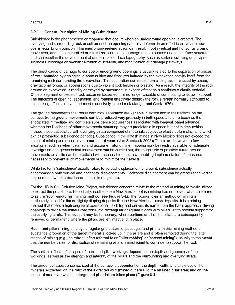
acted; on the ratio of the extracted void (mined out area) to the retained pillar area; and on the
extent of area over which underground pillar failure takes place (Figure 6-1).
6.2.1 General Principles of Mining Subsidence
Subsidence is the phenomenon or response that occurs when an underground opening is created. The overlying and surrounding rock or soil around the opening naturally deforms in an effort to arrive at a new overall equilibrium position. This equilibrium-seeking action can result in both vertical and horizontal ground movement, and, if not controlled or minimized, can cause damage to both surface and subsurface structures and can result in the development of undesirable surface topography, such as surface cracking or collapse, sinkholes, blockage or re-channelization of streams, and modification of drainage pathways.
The direct cause of damage to surface or underground openings is usually related to the separof rock, bounded by geological discontinuities and fractures induced by the excavation activity itself, from the remaining rock surrounding the excavation. This separation can result from sliding action caused by stress, gravitational forces, or accelerations due to violent rock failures or blasting. As a result, the integrity of the rock around an excavation is readily destroyed by movement in excess of that as a continuous elastic material. Once a segment or piece of rock becomes loosened, it is no longer capable of contributing to its own support. The functions of opening, separation, and rotation effectively destroy the rock strength normally attributed to interlocking effects, in even the most extensively jointed rock (Jaeger and Cook 1976).
The ground movements that result from rock separation are variable in extent and in their effects on the surface. Some ground movements can be predicted very precisely in both space and time (such as the anticipated immediate and complete subsidence occuwhereas the likelihood of other movements occurring may be predictable in space but not in time (which include those associated with overlying strata comprised of materials subject to plastic deformation and which exhibit protracted subsidence periods). Subsidence in the potash mines in New Mexico does not exceed the height of mining and occurs over a number of years (Van Sambeek 2008)).There are, however, a few situations, such as when detailed and accurate historic mine mapping may be readily available, or adequate investigation and geotechnical assessment can be carried out, the magnitude of possible future ground movements on a site can be predicted with reasonable accuracy, enabling implementation of measures necessary to prevent such movements or to minimize their effects.
While the term “subsidence’ usually refers to vertical displacement of a point, subsidence actually encompasses both vertical and horizontal displacements. Horizontal displacement can be greater than verdisplacement when subsidence is small
For the HB In-Situ Solution Mine Project, subsidence concerns relate to the method of mining formerly utilized to extract the potash ore. Historically, southeastern New Mexico potash mining has employed what is referreto as the “room-and-pillar” mining method (see Figure 5-1). The room-and-pillar method of mining is particularly suited for flat or slightly dipping deposits like the New Mexico potash deposits. It is a mining method that offers a high degree of operational flexibility and derives its name from the basic approach: drivingopenings to divide the mineralized zone into rectangular or square blocks with pillars left to provide support forthe overlying strata. This support may be temporary, where portions or all of the pillars are subsequently removed or permanent, where the pillars are left intact and in place.
Room-and-pillar mining employs a regular grid pattern of passages and pillars. In this mining method a substantial proportion of the target mineral is locked up in the pillars and is often removed during the latter stages of mining (e.g., on retreat, often referred to as ”pillar robbing” or “second mining”), usually to the extent that the number, size, or distribution of remaining pillars is insufficient to continue to support the roof.
The surface effects of collapse of roomworkings, as well as the strength and in
The amount of subsidence realized at the surface is dependent on the depth, width, and thickness of theminerals extr
Regional Geology and Issues Report; HB In-Situ Solution Mine Project July 2010
AECOM 6-4
as
surface.
r cannot .
Maximum subsidence depth, however, is seldom observed, due to one or more of the following reasons:
Figure 6-1 Subsidence Effects Zones
The rate of subsidence is largely dependent on the type of material being mined. From a mine design and operations perspective, subsidence issues largely relate to the stability and safety of an excavation in rockdetermined by:
1. The extent to which disruptive displacements can be prevented; and
2. The extent to which disruptive displacements can be controlled. These same primary design objectives similarly influence the potential to affect the surface, and the degree of effect at the
As a general rule, the value of the maximum subsidence (i.e., the depth of subsidence) that could occuexceed the thickness of the zone of mineral extracted (i.e., the mining thickness) (Van Sambeek 2008)
• Subsidence actually spreads over an area somewhat larger than the mined area, so the depth of subsidence realized is proportionately less than the mined area.
Regional Geology and Issues Report; HB In-Situ Solution Mine Project July 2010
AECOM 6-5
• Convergence, or closure of the mined area is never fully complete or total, so some voids inevitably remain, reducing the amount of subsidence.
• The overlying strata (i.e., overlying rocks) expand slightly in volume due to breakage as the ground moves downward into the mined area, resulting in a “bulking” effect, which contributes to a reduction in subsidence volume and depth.
• The subsidence process can be slow for rocks that creep—several hundred (or more) years may be required for ultimate subsidence to occur.
It is important to note that both historic data and anecdotal evidence suggest that for the southeastern New Mexico potash mines, virtual completion of the maximum surface subsidence profile occurs within just a few years (i.e., 5 to 7 years) after completion of second mining (Intrepid Potash/Shaw 2008c). Minor, protracted subsidence or creep may continue to occur over an extended period of time thereafter. Potash, like salt, is classified as an elastoplastic rock. Elastoplastic rocks are massive, homogeneous, and isotropic, but possess load-deformation characteristics that deviate significantly from linearity.
Prediction of the complete subsidence profile (i.e., maximum amount of subsidence anticipated) can generally be accomplished through either an “empirical approach” or a “phenomenological approach.”
The “empirical approach” is based primarily on experience, intuition, and observation of ground motions without particular regard for the principles of deformable body mechanics. For instance, studies have been conducted over a number of years by the British National Coal Board on over 150 coal mines located throughout Great Britain, with the results of the studies being put in a graphical format for use by mining engineers. Based on this extensive data, one can evaluate the probable degree and extent of surface subsidence by entering mine design parameters onto various graphical displays that yield reliable predictive data, typically within a range of accuracy of ±10 percent (British National Coal Board 1975).
The “phenomenological approach” employs mathematical analyses. The ground around the opening is assumed to behave as an elastic, elastic-plastic, or viscoelastic-plastic continuum and various mathematical theories are applied in order to develop general equations reflecting the subsidence profile. Finite element models also have been employed in studies of this type. The chief deficiency in this approach is the difficulty in accurately modeling the structure and the lack of accurate physical property data (e.g., elastic constants, strengths, etc.) to enable computation of the equations for a site-specific application.
Measurement of subsidence data is critical in assessing and predicting the effects of subsidence. As the ground surface subsides, both horizontal and vertical strains develop. These strains are compressive in nature in areas overlying the mine void and are tensile in nature in areas exterior to the inflection point in the
in is evaluated by measuring the change in vertical position of marker points relative to a
f known
ully
subsidence profile curve.
Subsidence prediction is typically achieved through monitoring vertical and horizontal movement in order toprovide the data necessary for analysis. In essence:
• Vertical strafixed, stable point located outside the area of subsidence effects; and
• Horizontal strain is evaluated by measuring the horizontal displacement between two points olocation.
In general, it is the horizontal strain that is the most damaging to surface structures.
Subsidence terminology is comprised of a number of mathematical factors, all of which are necessary to fevaluate subsidence effects.
Regional Geology and Issues Report; HB In-Situ Solution Mine Project July 2010
AECOM 6-6
• Horizontal Displacement: The horizontal component of subsidence, or horizontal displacement, is greatest at the point of maximum tilt and declines to a value of zero at the limit of subsidence and at the point of maximum subsidence.
• Strain: Strain is caused by the bending and differential horizontal movements in the strata. It is determined from monitored survey data by calculating the horizontal change in length of a section of a
ith the maximum curvature and the maximum tensile strains
subsidence profile and dividing this by the initial horizontal length of that section. Where the ground has been extended, the ground is in tension. If the section has been shortened, the ground is in compression. Maximum strains coincide woccurring toward the edges of the workings, while maximum compressive strains occur toward the bottom of the subsidence trough.
• Angle of Influence: The angle of influence, sometimes called the angle of draw or limit angle, is the angle of inclination from the horizontal (or vertical) of the line connecting the edge of the workings athe edge of the subsidence area (see Figure 6-1).
•
nd
Tilt: Tilt is calculated as the change in subsidence between two points, divided by the distance between those points. The maximum tilt, or the steepest portion of the subsidence profile, occurs at the point of inflection in the subsidence trough, where subsidence is roughly equal to approximately one-half of maximum subsidence.
• Curvature: Curvature is defined as the change in tilt between two adjacent sections of the tilt profdivided by the average length of those sections. Curvature is convex over the edges of the workingsand concave toward the bottom of the subsidence trough.
6.2.2 Mining Subsidence in the Project Area
Mining subsidence in the HB In-Situ Solution Mine Project area is of concern relative to the existence of historic subsidence, potential future subsidence effects that may be caused by mining activities
ile, ,
, and potential
of the the degree of extraction. For full extraction (100 percent) of the mineable zone, it is
. a,
dence. There is direct evidence of this phenomena from
979).
. Initial values (pre-mining) were established through a monitoring letion of first mining and
profile, largely
tected surface movement was approximately 1.8 feet; however, the data clearly indicate that subsidence activity continued well beyond the cessation of active mining. Thus, the subsidence measured some 10 months after conclusion of mining represented approximately 40 percent of
incremental subsidence that may occur in conjunction with or as a result of the proposed in-situ solutionmining.
While the HB In-Situ Solution Mine Project is proposed to be carried out in a relatively rural area, there is existing infrastructure that could be affected by subsidence, including surface structures, roadways, pipelines, oil and gas wells, and utilities throughout the project area.
6.2.2.1 Historic Subsidence
Historic data and observations of subsidence effects in the potash areas of southeast New Mexico have demonstrated that the relationship between the extent of vertical surface subsidence and the thicknessmining horizon varies with considered likely that the maximum surface subsidence will approach that of the thickness of the mined zoneThis is due to evidence suggesting that there is very little breakup and bulking occurring in the overlying stratwhich, when present, tends to limit the degree of subsimining activity that was conducted in supposed “caved” hanging walls about 50 to 100 feet above the earlier mined horizons. In those applications, the ore beds had suffered no noticeable structural deformation other than the elevation differential induced by subsidence (Golder and Associates 1
In evaluating surface subsidence as a function of time, Golder and Associates (1979) examined monitoring data from the nearby Wills-Weaver Mineprogram that commenced in June 1963. Comparative values were assessed on compagain at completion of second mining in February 1964. Data reflected an irregular subsidence attributed to local extraction ratio variations within the mine panel, but were indicative of a relatively uniform rate of subsidence, with a mean rate of slightly less than 1 inch per month. At completion of monitoring (December 1964), the maximum de
Regional Geology and Issues Report; HB In-Situ Solution Mine Project July 2010
AECOM 6-7
d
um recorded to date; however, it also was noted that in this case
is present at a horizon that is approximately 500 feet e
6.5 feet thick or less, with an average mining Mine
was extracted during what was referred to as “first mining”
The increase in vertical stress is offset by
the plastic nature of the salt (i.e., the salt adjusts for the change in stress through very slow, flow-like es to the edges (surrounding intact rock) of the mine
or mining” was carried out by removing certain portions of the pillars and/or barriers in order to increase
arried over a reduced cross-sectional area. The fficient to cause failure of the pillar remnants.
d
the mined zone thickness of 4.3 feet with an average extraction ratio of 80 percent to 85 percent. Golder anAssociates (1979) recognized that subsidence continued well beyond the monitoring period and that total movement would exceed the 1.8 feet maximthe shallow mining horizon (4.3 feet) provided for a high aspect ratio (pillar width to pillar height), thus contributing to proportionately greater pillar support capacity.
In evaluating the potential for subsidence in the project area, it is necessary to consider the lithology, thickness, and vertical locations of the strata overlying the historic potash workings, and existing (historic) subsidence.
Within the Salado Formation, the No. 1 potash zone down from the top of the formation. Due to variations in thickness of the overlying formations and the dip of thbeds, the No. 1 zone can occur from about 675 feet to as much as 1,450 feet below ground surface (bgs). Most areas of the HB potash mines were extracted in a zonethickness of about 5 feet (Intrepid Potash/Shaw 2008c). For this reason, surface subsidence over the HBarea would not be expected to be as great as that for surrounding mines with thicker ore extraction heights.
According to Intrepid Potash, records indicate that during the period when PCA operated the HB Mine, approximately 63 percent of the ore reserve(Intrepid Potash/Shaw 2008c). Removal of that percentage of the ore reserve results in a corresponding decrease in the available cross-sectional area remaining to support the overlying rock, resulting in an increasein the magnitude of vertical stress on the ore in the remnant pillars.
movements) and through redistribution of the stressworkings. This pressure redistribution is referred to as “arch action.”
The remaining 37 percent of the ore reserve was left in-place in the form of supporting pillars and/or barriers as mining advanced to its furthest extent. Once “first mining” was completed to its furthest extent, retreat “second overall ore recovery as each mine panel was being abandoned. This second mining was typically accomplished by taking cuts through the center of the pillars, generally 90 degrees offset from each other, so that only the four corners of each pillar remained as support. As a result, the pillar remnants are insufficient to support the overlying ground because the stress must be cincrease in localized stress is su
Pillar failure occurs shortly after second mining is completed, typically, within about one month after seconmining (Intrepid Potash/Shaw 2008c). Shortly after the secondary removal cuts are made within the pillar, the residual corner pillars begin to compress or crush due to the increased vertical stress in the overlying rock, generally through the sloughing or spalling off of slabs at the midriff of the pillar, with the pillar ultimately assuming an hour-glass shape. As a result of the sloughing and spalling action, a debris pile accumulates on the floor surrounding the pillar. In the advanced stages of compressive action (as closure or full convergence of the mining void is approached), the roof may receive some degree of support from the debris pile, ultimately delaying or precluding full convergence in a localized area of the mine. This same principle is a recognized result of underground backfilling accomplished through placement of gob or non-economic material within mined-out areas.
During the second mining, PCA extracted a nominal 20 percent of the remaining ore in place (i.e., of the 37 percent that remained as pillars and/or barriers)(Intrepid Potash/Shaw 2008a). As a result, the total extraction rate (calculated as = 0.63 + [0.20 x 0.37]) reached approximately 70.4 percent of the ore reserve.
Second mining was employed extensively throughout the HB Eddy Mine in order to increase ore recovery. While subsidence was generally observed to begin within one month following completion of second mining, various studies indicate that small settlements on the order of 1 to 2 feet continued to occur over a period of several years thereafter.
Regional Geology and Issues Report; HB In-Situ Solution Mine Project July 2010

AECOM 6-8
al feet] + [0.5 x 6 feet]).
localized
real extent of subsidence extends beyond the limits of the mine workings and is defined by the angle of influence, which has been observed at various local mines to range from 45 degrees to 55 degrees,
his
that presumably also depict the effects of subsidence over mined areas. Stress cracks are present in areas of
the north line, 2,580 feet from the west line (Goodbar 2010). Located over the HB
Several subsidence studies were conducted in the late 1950s by United States Potash (USP) (Intrepid Potash/Shaw 2008f). Findings from those studies suggest that first mining ore removal had the potential toinfluence the surface at about 20 percent of the mined height, with second mining contributing an additional 50percent of the mined height. Thus, the total surface expression of subsidence over a 6-foot-thick nominmining zone would approximate 4.2 feet (calculated as [0.2 x 6
The removal of potash ore via historical underground mining operations in the project area resulted in surficial depressions (i.e., subsidence expressions) and near-vertical stress cracks (Intrepid Potash/Shaw 2008c). The a
with the HB potash mines more closely approximating 45 degrees (measured from the horizontal).
Specific examples of surface exposures of subsidence effects in the project area include the alluvium contained “in a depression south of Section 2 and adjacent to Highway 31” (Intrepid Potash/Shaw 2008d). Tfeature shows ditch-like, parallel depressions that resemble typical subsidence fractures over mining subsidence. South of Highway 31 is an area where drainage has been disturbed by a series of parallel trends
Sections 23 and 26, T20S, R29E (Figure 6-2). It is likely that these types of features may be present throughout the project area wherever historic underground workings exist.
Figure 6-2 Photo of Surface Tension Cracks
Other possible mining-related subsidence features occurred on Eddy County Road 238 (T20S, R29E, Section 23, 2,200 feet from
Regional Geology and Issues Report; HB In-Situ Solution Mine Project July 2010
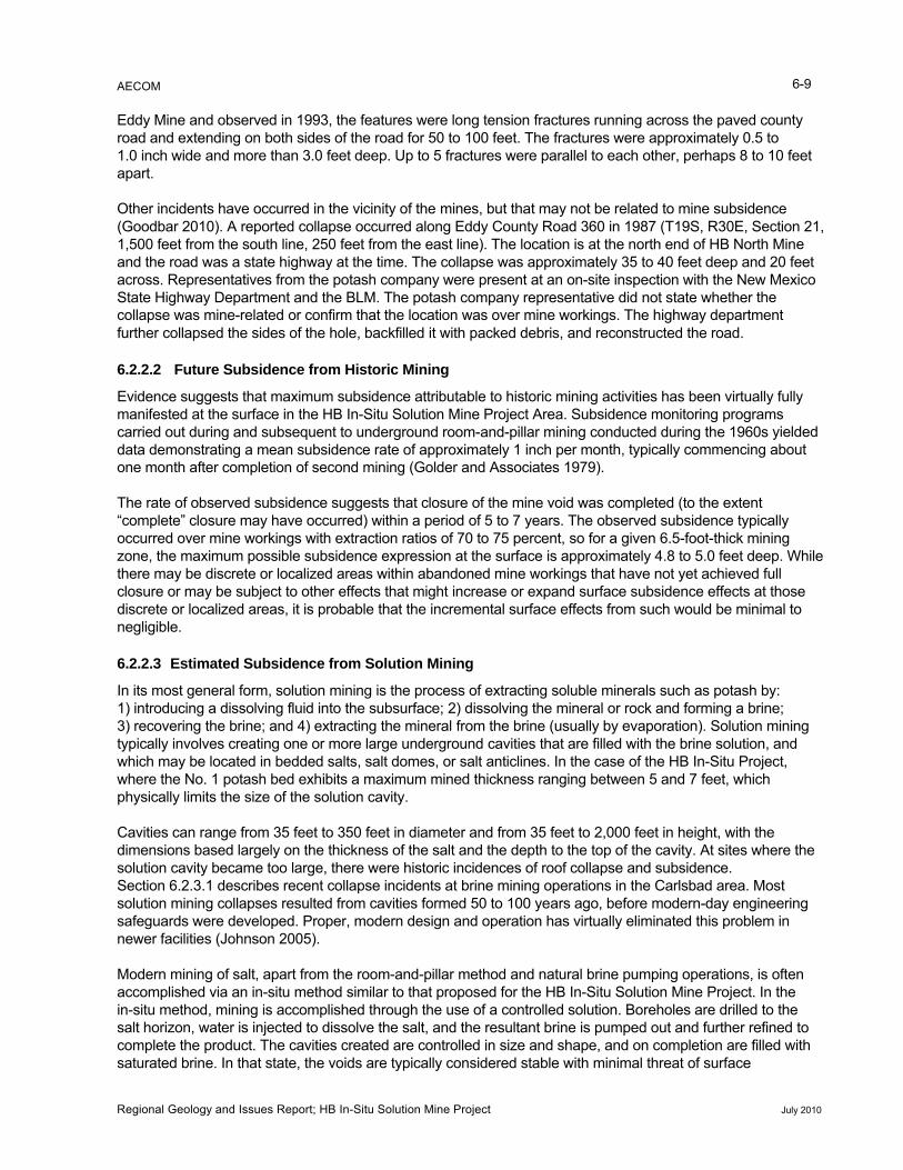
AECOM 6-9
unty
Other incidents have occurred in the vicinity of the mines, but that may not be related to mine subsidence
e
the
collapse was mine-related or confirm that the location was over mine workings. The highway department
yielded nth, typically commencing about
one month after completion of second mining (Golder and Associates 1979).
The rate of observed subsidence suggests that closure of the mine void was completed (to the extent “complete” closure may have occurred) within a period of 5 to 7 years. The observed subsidence typically occurred over mine workings with extraction ratios of 70 to 75 percent, so for a given 6.5-foot-thick mining zone, the maximum possible subsidence expression at the surface is approximately 4.8 to 5.0 feet deep. While there may be discrete or localized areas within abandoned mine workings that have not yet achieved full closure or may be subject to other effects that might increase or expand surface subsidence effects at those discrete or localized areas, it is probable that the incremental surface effects from such would be minimal to negligible.
6.2.2.3 Estimated Subsidence from Solution Mining
In its most general form, solution mining is the process of extracting soluble minerals such as potash by: 1) introducing a dissolving fluid into the subsurface; 2) dissolving the mineral or rock and forming a brine; 3) recovering the brine; and 4) extracting the mineral from the brine (usually by evaporation). Solution mining typically involves creating one or more large underground cavities that are filled with the brine solution, and which may be located in bedded salts, salt domes, or salt anticlines. In the case of the HB In-Situ Project, where the No. 1 potash bed exhibits a maximum mined thickness ranging between 5 and 7 feet, which physically limits the size of the solution cavity.
Cavities can range from 35 feet to 350 feet in diameter and from 35 feet to 2,000 feet in height, with the dimensions based largely on the thickness of the salt and the depth to the top of the cavity. At sites where the solution cavity became too large, there were historic incidences of roof collapse and subsidence. Section 6.2.3.1 describes recent collapse incidents at brine mining operations in the Carlsbad area. Most solution mining collapses resulted from cavities formed 50 to 100 years ago, before modern-day engineering safeguards were developed. Proper, modern design and operation has virtually eliminated this problem in newer facilities (Johnson 2005).
Modern mining of salt, apart from the room-and-pillar method and natural brine pumping operations, is often accomplished via an in-situ method similar to that proposed for the HB In-Situ Solution Mine Project. In the
e use of a controlled solution. Boreholes are drilled to the salt horizon, water is injected to dissolve the salt, and the resultant brine is pumped out and further refined to
d with
Eddy Mine and observed in 1993, the features were long tension fractures running across the paved coroad and extending on both sides of the road for 50 to 100 feet. The fractures were approximately 0.5 to 1.0 inch wide and more than 3.0 feet deep. Up to 5 fractures were parallel to each other, perhaps 8 to 10 feet apart.
(Goodbar 2010). A reported collapse occurred along Eddy County Road 360 in 1987 (T19S, R30E, Section 21, 1,500 feet from the south line, 250 feet from the east line). The location is at the north end of HB North Minand the road was a state highway at the time. The collapse was approximately 35 to 40 feet deep and 20 feet across. Representatives from the potash company were present at an on-site inspection with the New MexicoState Highway Department and the BLM. The potash company representative did not state whether
further collapsed the sides of the hole, backfilled it with packed debris, and reconstructed the road.
6.2.2.2 Future Subsidence from Historic Mining
Evidence suggests that maximum subsidence attributable to historic mining activities has been virtually fully manifested at the surface in the HB In-Situ Solution Mine Project Area. Subsidence monitoring programs carried out during and subsequent to underground room-and-pillar mining conducted during the 1960sdata demonstrating a mean subsidence rate of approximately 1 inch per mo
in-situ method, mining is accomplished through th
complete the product. The cavities created are controlled in size and shape, and on completion are fillesaturated brine. In that state, the voids are typically considered stable with minimal threat of surface
Regional Geology and Issues Report; HB In-Situ Solution Mine Project July 2010
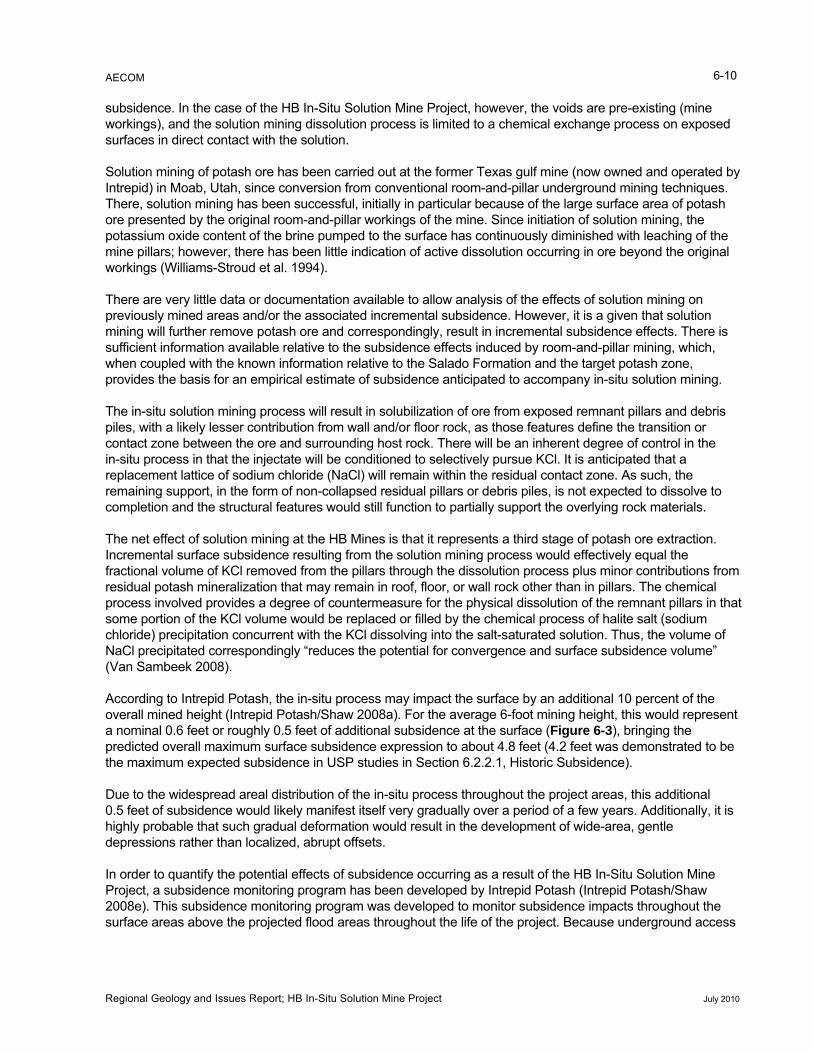
AECOM 6-10
sed
Solution mining of potash ore has been carried out at the former Texas gulf mine (now owned and operated by s.
g on previously mined areas and/or the associated incremental subsidence. However, it is a given that solution
ingly, result in incremental subsidence effects. There is
res define the transition or the
lume of KCl removed from the pillars through the dissolution process plus minor contributions from ock other than in pillars. The chemical
r the physical dissolution of the remnant pillars in that
f
8a). For the average 6-foot mining height, this would represent
a nominal 0.6 feet or roughly 0.5 feet of additional subsidence at the surface (Figure 6-3), bringing the to be
, abrupt offsets.
subsidence. In the case of the HB In-Situ Solution Mine Project, however, the voids are pre-existing (mine workings), and the solution mining dissolution process is limited to a chemical exchange process on exposurfaces in direct contact with the solution.
Intrepid) in Moab, Utah, since conversion from conventional room-and-pillar underground mining techniqueThere, solution mining has been successful, initially in particular because of the large surface area of potash ore presented by the original room-and-pillar workings of the mine. Since initiation of solution mining, the potassium oxide content of the brine pumped to the surface has continuously diminished with leaching of the mine pillars; however, there has been little indication of active dissolution occurring in ore beyond the original workings (Williams-Stroud et al. 1994).
There are very little data or documentation available to allow analysis of the effects of solution minin
mining will further remove potash ore and correspondsufficient information available relative to the subsidence effects induced by room-and-pillar mining, which, when coupled with the known information relative to the Salado Formation and the target potash zone, provides the basis for an empirical estimate of subsidence anticipated to accompany in-situ solution mining.
The in-situ solution mining process will result in solubilization of ore from exposed remnant pillars and debris piles, with a likely lesser contribution from wall and/or floor rock, as those featucontact zone between the ore and surrounding host rock. There will be an inherent degree of control inin-situ process in that the injectate will be conditioned to selectively pursue KCl. It is anticipated that a replacement lattice of sodium chloride (NaCl) will remain within the residual contact zone. As such, the remaining support, in the form of non-collapsed residual pillars or debris piles, is not expected to dissolve to completion and the structural features would still function to partially support the overlying rock materials.
The net effect of solution mining at the HB Mines is that it represents a third stage of potash ore extraction. Incremental surface subsidence resulting from the solution mining process would effectively equal the fractional voresidual potash mineralization that may remain in roof, floor, or wall rprocess involved provides a degree of countermeasure fosome portion of the KCl volume would be replaced or filled by the chemical process of halite salt (sodium chloride) precipitation concurrent with the KCl dissolving into the salt-saturated solution. Thus, the volume oNaCl precipitated correspondingly “reduces the potential for convergence and surface subsidence volume” (Van Sambeek 2008).
According to Intrepid Potash, the in-situ process may impact the surface by an additional 10 percent of theoverall mined height (Intrepid Potash/Shaw 200
predicted overall maximum surface subsidence expression to about 4.8 feet (4.2 feet was demonstrated the maximum expected subsidence in USP studies in Section 6.2.2.1, Historic Subsidence).
Due to the widespread areal distribution of the in-situ process throughout the project areas, this additional 0.5 feet of subsidence would likely manifest itself very gradually over a period of a few years. Additionally, it ishighly probable that such gradual deformation would result in the development of wide-area, gentle depressions rather than localized
In order to quantify the potential effects of subsidence occurring as a result of the HB In-Situ Solution Mine Project, a subsidence monitoring program has been developed by Intrepid Potash (Intrepid Potash/Shaw 2008e). This subsidence monitoring program was developed to monitor subsidence impacts throughout the surface areas above the projected flood areas throughout the life of the project. Because underground access
Regional Geology and Issues Report; HB In-Situ Solution Mine Project July 2010
AECOM 6-11
Figure 6-3 Representative Potential Subsidence Cross Section
s, will be established, as depicted in Table 6-1.
is no longer viable, the proposed monitoring program will utilize existing (converted) core holes aligned in several transects across the flooded workings to detect vertical or horizontal movement through global positioning system survey methods and visual verification.
Twenty-four existing core holes (Figure 6-4), each with an established benchmark, are to be tied to a base reference location and elevation utilizing the existing project coordinate system. Core holes will be located both interior to and exterior to the projected flood zone. Baseline (pre-flooding) data obtained on each location will include monument elevations and coordinates. A total of five linear transects, which bisect each of the respective mine working
Table 6-1 Subsidence Monitoring Transects
Transect Flooded Working Orientation
HB-SM1 HB Eddy SW to NE across central portion of working (short axis)
HB-SM2 HB South NW to SE across central portion of working (short axis)
HB-SM3 HB North SW to NE across central portion of working (short axis)
HB-SM4 HB North NW to SE across north portion of working (long axis)
HB-SM5 HB Crescent NNW to SSE longitudinal axis across extent of working Intrepid Potash/Shaw (2008e)
Regional Geology and Issues Report; HB In-Situ Solution Mine Project July 2010
AECOM 6-12
Monitoring Program Figure 6-4 Subsidence
Regional Geology and Issues Report; HB In-Situ Solution Mine Project July 2010
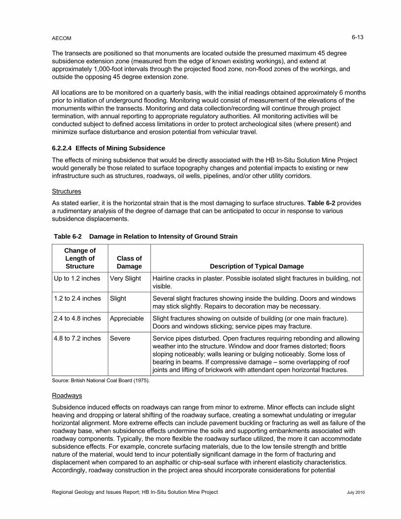
AECOM 6-13
The transects are positioned so that monuments are located outside the presumed maximum 45 degree subsidence extension zone (measured from the edge of known existing workings), and extend at approximately 1,000-foot intervals through the projected flood zone, non-flood zones of the workings, and outside the opposing 45 degree extension zone.
All locations are to be monitored on a quarterly basis, with the initial readings obtained approximately 6 months prior to initiation of underground flooding. Monitoring would consist of measurement of the elevations of the monuments within the transects. Monitoring and data collection/recording will continue through project termination, with annual reporting to appropriate regulatory authorities. All monitoring activities will be conducted subject to defined access limitations in order to protect archeological sites (where present) and minimize surface disturbance and erosion potential from vehicular travel.
6.2.2.4 Effects of Mining Subsidence
The effects of mining subsidence that would be directly associated with the HB In-Situ Solution Mine Project would generally be those related to surface topography changes and potential impacts to existing or new infrastructure such as structures, roadways, oil wells, pipelines, and/or other utility corridors.
Structures
As stated earlier, it is the horizontal strain that is the most damaging to surface structures. Table 6-2 provides a rudimentary analysis of the degree of damage that can be anticipated to occur in response to various subsidence displacements.
Table 6-2 Damage in Relation to Intensity of Ground Strain
Change of Length of Structure
Class of Damage Description of Typical Damage
Up to 1.2 inches Very Slight Hairline cracks in plaster. Possible isolated slight fractures in building, not visible.
1.2 to 2.4 inches Slight Several slight fractures showing inside the building. Doors and windows may stick slightly. Repairs to decoration may be necessary.
2.4 to 4.8 inches Appreciable Slight fractures showing on outside of building (or one main fracture). Doors and windows sticking; service pipes may fracture.
4.8 to 7.2 inches Severe Service pipes disturbed. Open fractures requiring rebonding and allowing weather into the structure. Window and door frames distorted; floors sloping noticeably; walls leaning or bulging noticeably. Some loss of bearing in beams. If compressive damage – some overlapping of roof joints and lifting of brickwork with attendant open horizontal fractures.
Source: British National Coal Board (1975).
Roadways
Subsidence induced effects on roadways can range from minor to extreme. Minor effects can include slight heaving and dropping or lateral shifting of the roadway surface, creating a somewhat undulating or irregular horizontal alignment. More extreme effects can include pavement buckling or fracturing as well as failure of the roadway base, when subsidence effects undermine the soils and supporting embankments associated with roadway components. Typically, the more flexible the roadway surface utilized, the more it can accommodate
ing materials, due to the low tensile strength and brittle nature of the material, would tend to incur potentially significant damage in the form of fracturing and
ith inherent elasticity characteristics. Accordingly, roadway construction in the project area should incorporate considerations for potential
subsidence effects. For example, concrete surfac
displacement when compared to an asphaltic or chip-seal surface w
Regional Geology and Issues Report; HB In-Situ Solution Mine Project July 2010
AECOM 6-14
ting struction
t where effects are less severe and believed to be representative of probable maximum subsidence.
subsidence effects when selecting the type of surfacing material to be employed. Roadway damage resulfrom subsidence effects is typically addressed through road base and embankment cut and fill conprocedures employing base stabilization measures that accommodate the known or projected subsidence profile or reestablish the pre-subsidence alignmen
Active Oil Wells
Subsidence induced deformations of the strata can damage engineered structures such as abandonedproducing oil or gas wells located within the zone of influence of the movements. Subsidence effects on sucwells can include distortion of the boreholes, squeezing of casing, and shearing of casing. This is of significinterest with respect to the HB In-Situ Solution Mine Project due to the kno
or h
ant wn presence of six abandoned wells
al extent of the proposed flood zone (see Figure 5-2). Five of the otprint of the HB South flood zone, while one additional abandoned
ng
eaver Mine subsidence data (Golder and Associates 1979), along with data obtained from more
zed as
ith surface subsidence immediately .
rlying trata suffer comparatively limited distortion and disturbance.
l pillar level of support such trolled rate and likely u g h
about 1 inch per month following conclusion of mining).
b effects t.
o ff mine workings
45 degrees from the vertical. More sign in an influence bo grees.
In the case of the Wills-Weaver Min tion ratio ground, and centered within re“closures at the mine horizon level t the
t been sufficient to cause problems.”
he conclusions were developed some fifteen years following completion of mining (a point in time
l
and one producing gas well within the areabandoned wells are located within the fowell is located within the footprint of the HB Eddy flood zone. Records indicate that the abandonment procedures were documented by PCA (by actually conducting the plugging activities, observing the pluggieffort, or reviewing the available records) (Intrepid Potash/Shaw 2008b).
The Wills-Wextensive monitoring programs carried out at other nearby mines (e.g., U.S. Borax and Chemical Corporation)provided a fairly detailed understanding of subsidence phenomena within the southeastern New Mexico potash areas and the potential to affect oil and gas infrastructure. Pertinent conclusions can be summarifollows:
• In areas of high extraction, the mining horizon will close, wfollowing
• The ove
• Residua
subsided s
s provide a that subsidence develops at a concontinues ntil the minin orizon achieves virtual closure (which the data suggest occurs at a rate of
• Surface sumine support is intac
sidence decrease with the proximity to the edge of mine workings or areas where
• The zone the edge o
f disturbance o strata above the mine workings extends beyond the vertical line defined by and regional data suggests that the angle of influence is on the order of
ificant subsidence disturbance likely occurs withangle of a ut 30 de
e, for three producing oil wells situated in 70 feet to 75 percent extractained pillars of approximately 150-foot radius, it was concluded that
would have impacted the oil wells because of the limited pillar sizes, bulevel of disturbance has evidently no
Given that twhen maximum subsidence effects would have been fully manifested), and no reported effects to the three producing wells were noted, it is probable that sufficient integrity was retained within the centroidal portion of the high aspect ratio pillar to have negligible effects on the well casing. There is no data to suggest any reported effects on the well casings subsequent to the 1979 date of publication.
What this means with respect to oil and gas wells situated within the HB In-Situ Solution Mine Project area is that it is likely that subsidence effects can be similarly assessed through consideration of site-specific welconstruction data and knowledge of local subsidence effects to date.
Regional Geology and Issues Report; HB In-Situ Solution Mine Project July 2010
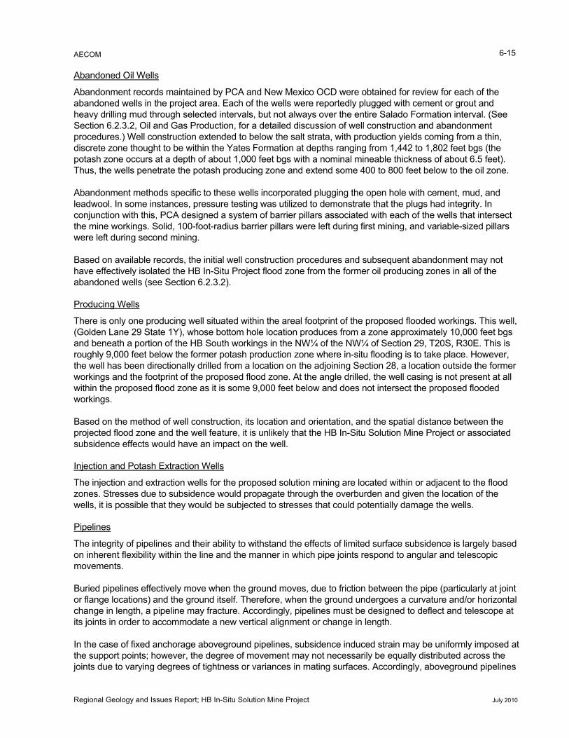
AECOM 6-15
Abandoned Oil Wells
Abandonment records maintained by PCA and New Mexico OCD were obtained for review for each of the abandoned wells in the project area. Each of the wells were reportedly plugged with cement or grout and heavy drilling mud through selected intervals, but not always over the entire Salado Formation intervaSection 6.2.3.2, Oil and Gas Production, for a deta
l. (See iled discussion of well construction and abandonment
ll construction extended to below the salt strata, with production yields coming from a thin, ught to be within the Yates Formation at depths ranging from 1,442 to 1,802 feet bgs (the
pillars
Based on available records, the initial well construction procedures and subsequent abandonment may not
procedures.) Wediscrete zone thopotash zone occurs at a depth of about 1,000 feet bgs with a nominal mineable thickness of about 6.5 feet). Thus, the wells penetrate the potash producing zone and extend some 400 to 800 feet below to the oil zone.
Abandonment methods specific to these wells incorporated plugging the open hole with cement, mud, and leadwool. In some instances, pressure testing was utilized to demonstrate that the plugs had integrity. In conjunction with this, PCA designed a system of barrier pillars associated with each of the wells that intersect the mine workings. Solid, 100-foot-radius barrier pillars were left during first mining, and variable-sizedwere left during second mining.
have effectively isolated the HB In-Situ Project flood zone from the former oil producing zones in all of the abandoned wells (see Section 6.2.3.2).
Producing Wells
There is only one producing well situated within the areal footprint of the proposed flooded workings. This well, et bgs his is
the former potash production zone where in-situ flooding is to take place. However, former
ll feature, it is unlikely that the HB In-Situ Solution Mine Project or associated
(Golden Lane 29 State 1Y), whose bottom hole location produces from a zone approximately 10,000 feand beneath a portion of the HB South workings in the NW¼ of the NW¼ of Section 29, T20S, R30E. Troughly 9,000 feet below the well has been directionally drilled from a location on the adjoining Section 28, a location outside theworkings and the footprint of the proposed flood zone. At the angle drilled, the well casing is not present at all within the proposed flood zone as it is some 9,000 feet below and does not intersect the proposed flooded workings.
Based on the method of well construction, its location and orientation, and the spatial distance between the projected flood zone and the wesubsidence effects would have an impact on the well.
Injection and Potash Extraction Wells
The injection and extraction wells for the proposed solution mining are located within or adjacent to the flood zones. Stresses due to subsidence would propagate through the overburden and given the location of the wells, it is possible that they would be subjected to stresses that could potentially damage the wells.
Pipelines
The integrity of pipelines and their ability to withstand the effects of limited surface subsidence is largely based
t zontal
d to deflect and telescope at
d at arily be equally distributed across the
joints due to varying degrees of tightness or variances in mating surfaces. Accordingly, aboveground pipelines
on inherent flexibility within the line and the manner in which pipe joints respond to angular and telescopic movements.
Buried pipelines effectively move when the ground moves, due to friction between the pipe (particularly at joinor flange locations) and the ground itself. Therefore, when the ground undergoes a curvature and/or horichange in length, a pipeline may fracture. Accordingly, pipelines must be designeits joints in order to accommodate a new vertical alignment or change in length.
In the case of fixed anchorage aboveground pipelines, subsidence induced strain may be uniformly imposethe support points; however, the degree of movement may not necess
Regional Geology and Issues Report; HB In-Situ Solution Mine Project July 2010
AECOM 6-16
chor points at every joint to ensure that the ground strain is evenly distributed. t
should be provided anAlternatively, or as a supplemental measure, a constraining harness can be employed at the joint to preventhe joint from exceeding its maximum allowable travel. Similarly, pipelines bedded in trenches should be constructed in a manner that ensures consistent distribution of strain through proper bedding measures that preclude excessive shear stresses causing breakage (Table 6-3).
Table 6-3 Types and Causes of Pipe Fracture
Failure Type Cause Prevention
Beam Uneven resistance of foundations, soil Flexible joints and uniform hardness of movement, or differential settlement. Caused by mining of shallow workings in extreme cases.
foundation.
Pull Thermal or drying shrinkage of pipe or site concrete, drying shrinkage
Flexible telescopic joints and gaps in site of clay soils. concrete at pipe joints.
Extension of ground through mining.
Shear Differential settlement of wall relative to pipe or vice versa. Can be cau
Flexible joints with joint separation <1 metesed by fissuring in
r.
subsided ground.
Thrust Restrained thermal or moisture expansion of pipe or compression due to subsidence.
Flexible telescopic joints.
Leverage Excessive angular displacements. Extreme cases of differential subsidence.
Flexible joints. Avoidance of excessive slew when laying.
Source: British National Coal Board (1975).
6.2.3 Subsidence Due to Brine Mining and Oil and Gas Activities
n, these wells are referred to as brine wells. Brine wells ct salt for use in oil and gas well drilling and workover fluids
wells suffered catastrophic collapse.
4, ensions
of 400 feet across and 120 feet deep, and reportedly continues to grow (OCD 2009b).
p.
production
6.2.3.1 Halite Solution Mining
Salt can be extracted from subsurface formations by using wells that inject fresh water to dissolve the salt. The saturated water is then extracted. In the Delaware Basiin the Delaware Basin are used to extra(Griswald 2009). Recently, a few brine
The first collapse occurred at Jim’s Water Service about 10 miles northwest of the project area in Section 2T18S, R28E. The collapse occurred on July 15, 2008, and the sinkhole created eventually reached dim
The second collapse occurred on November 3, 2008, at the Loco Hills Water Disposal located in Section 16, T17S, R30E, about 12 miles north of the project area. A week after the collapse, the diameter of the sinkhole was estimated to be 195 feet across. By May 2009, the sinkhole was 290 feet across and about 200 feet dee
Both wells had withdrawn brine from the Salado Formation, but the Loco Hills well also may have pulled brine out of the Rustler Formation. Both wells were oil and gas wells converted to brine mining wells, with the top of salt less than 500 feet bgs. It is estimated that the wells each produced 7 to 8 million barrels of brine. Brine mining creates a cavern in the salt formation and, if the top of the cavern becomes too large to support the overlying rock, collapse may occur. In both instances it is believed that the “reverse circulation” configuration of the wells contributed to a large opening at the top of the salt cavern that resulted in collapse of the overburden (Figure 6-5). Another factor common to both collapse incidents is that, although they occurred suddenly with little forewarning, both were located in remote areas, which lessened the risk to life and property (OCD 2009b).
Regional Geology and Issues Report; HB In-Situ Solution Mine Project July 2010
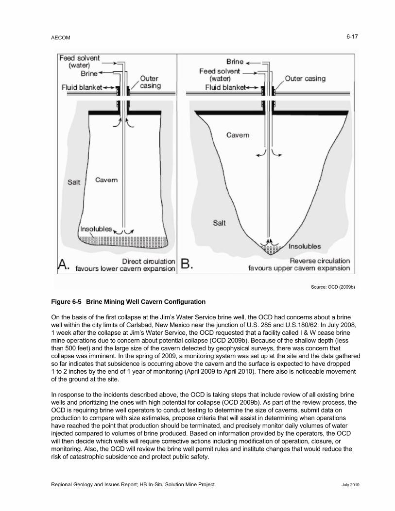
AECOM 6-17
8, ity called I & W cease brine
to have dropped
Figure 6-5 Brine Mining Well Cavern Configuration
On the basis of the first collapse at the Jim’s Water Service brine well, the OCD had concerns about a brine well within the city limits of Carlsbad, New Mexico near the junction of U.S. 285 and U.S.180/62. In July 2001 week after the collapse at Jim’s Water Service, the OCD requested that a facilmine operations due to concern about potential collapse (OCD 2009b). Because of the shallow depth (less than 500 feet) and the large size of the cavern detected by geophysical surveys, there was concern that collapse was imminent. In the spring of 2009, a monitoring system was set up at the site and the data gathered so far indicates that subsidence is occurring above the cavern and the surface is expected1 to 2 inches by the end of 1 year of monitoring (April 2009 to April 2010). There also is noticeable movement of the ground at the site.
In response to the incidents described above, the OCD is taking steps that include review of all existing brine wells and prioritizing the ones with high potential for collapse (OCD 2009b). As part of the review process, the OCD is requiring brine well operators to conduct testing to determine the size of caverns, submit data on production to compare with size estimates, propose criteria that will assist in determining when operations have reached the point that production should be terminated, and precisely monitor daily volumes of water injected compared to volumes of brine produced. Based on information provided by the operators, the OCDwill then decide which wells will require corrective actions including modification of operation, closure, or monitoring. Also, the OCD will review the brine well permit rules and institute changes that would reduce the risk of catastrophic subsidence and protect public safety.
Regional Geology and Issues Report; HB In-Situ Solution Mine Project July 2010
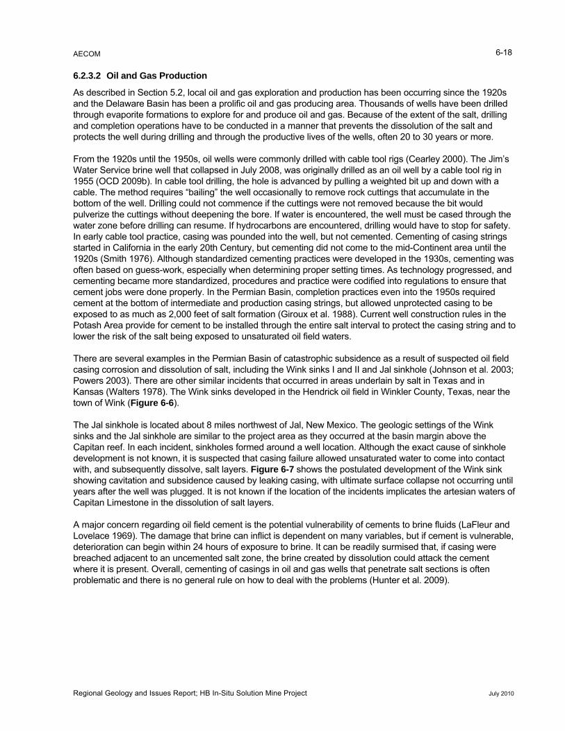
AECOM 6-18
6.2.3.2 Oil and Gas Production
As described in Section 5.2, local oil and gas exploration and production has been occurring since the 1920s and the Delaware Basin has been a prolific oil and gas producing area. Thousands of wells have been drilled through evaporite formations to explore for and produce oil and gas. Because of the extent of the salt, drilling and completion operations have to be conducted in a manner that prevents the dissolution of the salt and protects the well during drilling and through the productive lives of the wells, often 20 to 30 years or more.
From the 1920s until the 1950s, oil wells were commonly drilled with cable tool rigs (Cearley 2000). The Jim’s Water Service brine well that collapsed in July 2008, was originally drilled as an oil well by a cable tool rig in 1955 (OCD 2009b). In cable tool drilling, the hole is advanced by pulling a weighted bit up and down with a cable. The method requires “bailing” the well occasionally to remove rock cuttings that accumulate in the bottom of the well. Drilling could not commence if the cuttings were not removed because the bit would pulverize the cuttings without deepening the bore. If water is encountered, the well must be cased through the water zone before drilling can resume. If hydrocarbons are encountered, drilling would have to stop for safety. In early cable tool practice, casing was pounded into the well, but not cemented. Cementing of casing strings started in California in the early 20th Century, but cementing did not come to the mid-Continent area until the 1920s (Smith 1976). Although standardized cementing practices were developed in the 1930s, cementing was often based on guess-work, especially when determining proper setting times. As technology progressed, and cementing became more standardized, procedures and practice were codified into regulations to ensure that cement jobs were done properly. In the Permian Basin, completion practices even into the 1950s required cement at the bottom of intermediate and production casing strings, but allowed unprotected casing to be exposed to as much as 2,000 feet of salt formation (Giroux et al. 1988). Current well construction rules in the Potash Area provide for cement to be installed through the entire salt interval to protect the casing string and to lower the risk of the salt being exposed to unsaturated oil field waters.
There are several examples in the Permian Basin of catastrophic subsidence as a result of suspected oil field casing corrosion and dissolution of salt, including the Wink sinks I and II and Jal sinkhole (Johnson et al. 2003; Powers 2003). There are other similar incidents that occurred in areas underlain by salt in Texas and in Kansas (Walters 1978). The Wink sinks developed in the Hendrick oil field in Winkler County, Texas, near the town of Wink (Figure 6-6).
l, New Mexico. The geologic settings of the Wink they occurred at the basin margin above the
til of
hin 24 hours of exposure to brine. It can be readily surmised that, if casing were
The Jal sinkhole is located about 8 miles northwest of Jasinks and the Jal sinkhole are similar to the project area as Capitan reef. In each incident, sinkholes formed around a well location. Although the exact cause of sinkholedevelopment is not known, it is suspected that casing failure allowed unsaturated water to come into contact with, and subsequently dissolve, salt layers. Figure 6-7 shows the postulated development of the Wink sink showing cavitation and subsidence caused by leaking casing, with ultimate surface collapse not occurring unyears after the well was plugged. It is not known if the location of the incidents implicates the artesian watersCapitan Limestone in the dissolution of salt layers.
A major concern regarding oil field cement is the potential vulnerability of cements to brine fluids (LaFleur and Lovelace 1969). The damage that brine can inflict is dependent on many variables, but if cement is vulnerable,deterioration can begin witbreached adjacent to an uncemented salt zone, the brine created by dissolution could attack the cement where it is present. Overall, cementing of casings in oil and gas wells that penetrate salt sections is often problematic and there is no general rule on how to deal with the problems (Hunter et al. 2009).
Regional Geology and Issues Report; HB In-Situ Solution Mine Project July 2010
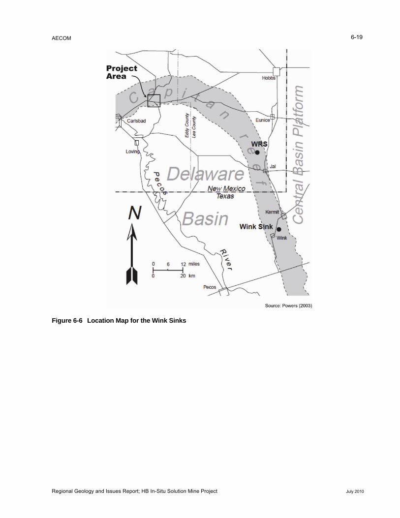
AECOM 6-19
Figure 6-6 Location Map for the Wink Sinks
Regional Geology and Issues Report; HB In-Situ Solution Mine Project July 2010
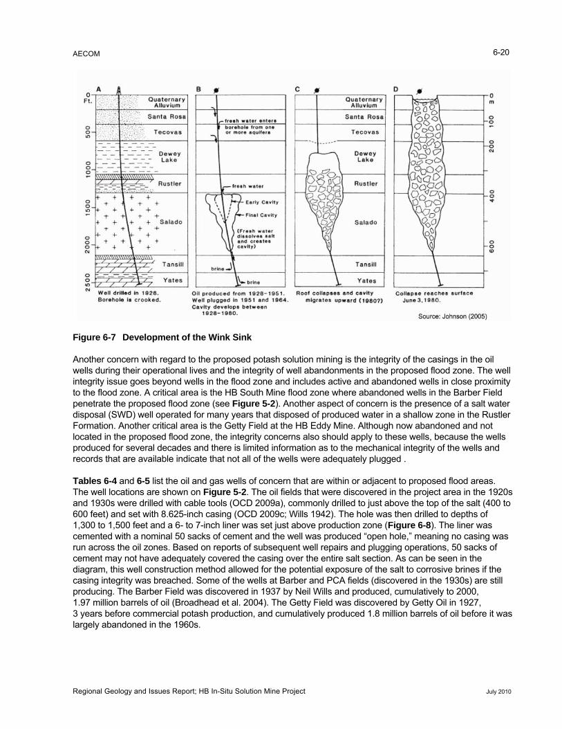
AECOM
Regional Geology and Issues Report; HB In-Situ Solution Mine Project July 2010
6-20
Figure 6-7 Development of the Wink Sink
Another concern with regard to the proposed potash solution mining is the integrity of the casings in the oil wells during their operational lives and the integrity of well abandonments in the proposed flood zone. The well integrity issue goes beyond wells in the flood zone and includes active and abandoned wells in close proximity to the flood zone. A critical area is the HB South Mine flood zone where abandoned wells in the Barber Field penetrate the proposed flood zone (see Figure 5-2). Another aspect of concern is the presence of a salt water disposal (SWD) well operated for many years that disposed of produced water in a shallow zone in the Rustler Formation. Another critical area is the Getty Field at the HB Eddy Mine. Although now abandoned and not located in the proposed flood zone, the integrity concerns also should apply to these wells, because the wells
information as to the mechanical integrity of the wells and wells were adequately plugged .
6-4 and 6-5 list the oil and gas wells of concern that are within or adjacent to proposed flood areas. The well locations are shown on Figure 5-2. The oil fields that were discovered in the project area in the 1920s and 1930s were drilled with cable tools (OCD 2009a), commonly drilled to just above the top of the salt (400 to 600 feet) and set with 8.625-inch casing (OCD 2009c; Wills 1942). The hole was then drilled to depths of 1,300 to 1,500 feet and a 6- to 7-inch liner was set just above production zone (Figure 6-8). The liner was cemented with a nominal 50 sacks of cement and the well was produced “open hole,” meaning no casing was run across the oil zones. Based on reports of subsequent well repairs and plugging operations, 50 sacks of cement may not have adequately covered the casing over the entire salt section. As can be seen in the diagram, this well construction method allowed for the potential exposure of the salt to corrosive brines if the casing integrity was breached. Some of the wells at Barber and PCA fields (discovered in the 1930s) are still producing. The Barber Field was discovered in 1937 by Neil Wills and produced, cumulatively to 2000, 1.97 million barrels of oil (Broadhead et al. 2004). The Getty Field was discovered by Getty Oil in 1927, 3 years before commercial potash production, and cumulatively produced 1.8 million barrels of oil before it was largely abandoned in the 1960s.
produced for several decades and there is limitedrecords that are available indicate that not all of the
Tables
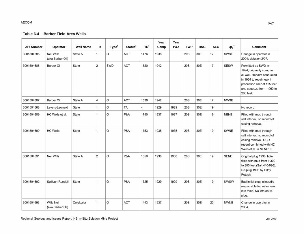
AECOM 6-21
Table 6-4 Barber Field Area Wells
er Operator Well Name # Type1 Status2 TD3 Year Year
QQ4 API Numb Comp P&A TWP RNG SEC Comment
Neil Wills (aka Barber Oil)
State A 1 ACT 1476 193001504685 O 38 20S 30E 17 SWSE Change in operator in 2004; violation 2/07.
Barber Oil State 2 3001504686 SWD ACT 1520 1942 20S 30E 17 SESW Permitted as SWD in 1994, originally comp as oil well. Repairs conducted in 1954 to repair leak in production liner at 125 feet and squeeze from 1,060 to 280 feet.
Barber Oil State A 4 ACT 1539 193001504687 O 42 20S 30E 17 NWSE
Levers-Leonard State 1 TA 4 193001504688 O 29 1929 20S 30E 19 No record.
HC Wells et al. State 1 P&A 1790 193001504689 O 37 1937 20S 30E 19 NENE Filled with mud through salt interval, no record of casing removal.
HC Wells State 1 P&A 1753 193001504690 O 35 1935 20S 30E 19 SWNE Filled with mud through salt interval, no record of casing removal. OCD record combined with HC Wells et al. in NENE19.
Neil Wills State A 2 P&A 1650 193001504691 O 38 1938 20S 30E 19 SENE Original plug 1938; hole filled with mud from 1,300 to 380 feet (Salt 410-996). Re-plug 1993 by Eddy Potash.
Sullivan-Rundall State 1 P&A 1325 193001504692 O 29 1929 20S 30E 19 NWSW Bad initial plug, allegedly responsible for water leak into mine. No info on re-plug.
3001504693 Wills Neil (ak ber Oil) a Bar
Colglazier 1 ACT 1443 19O 37 20S 30E 20 NWNE Change in operator in 2004.
Regional Geology and Issues Report; HB In-Situ Solution Mine Project July 2010
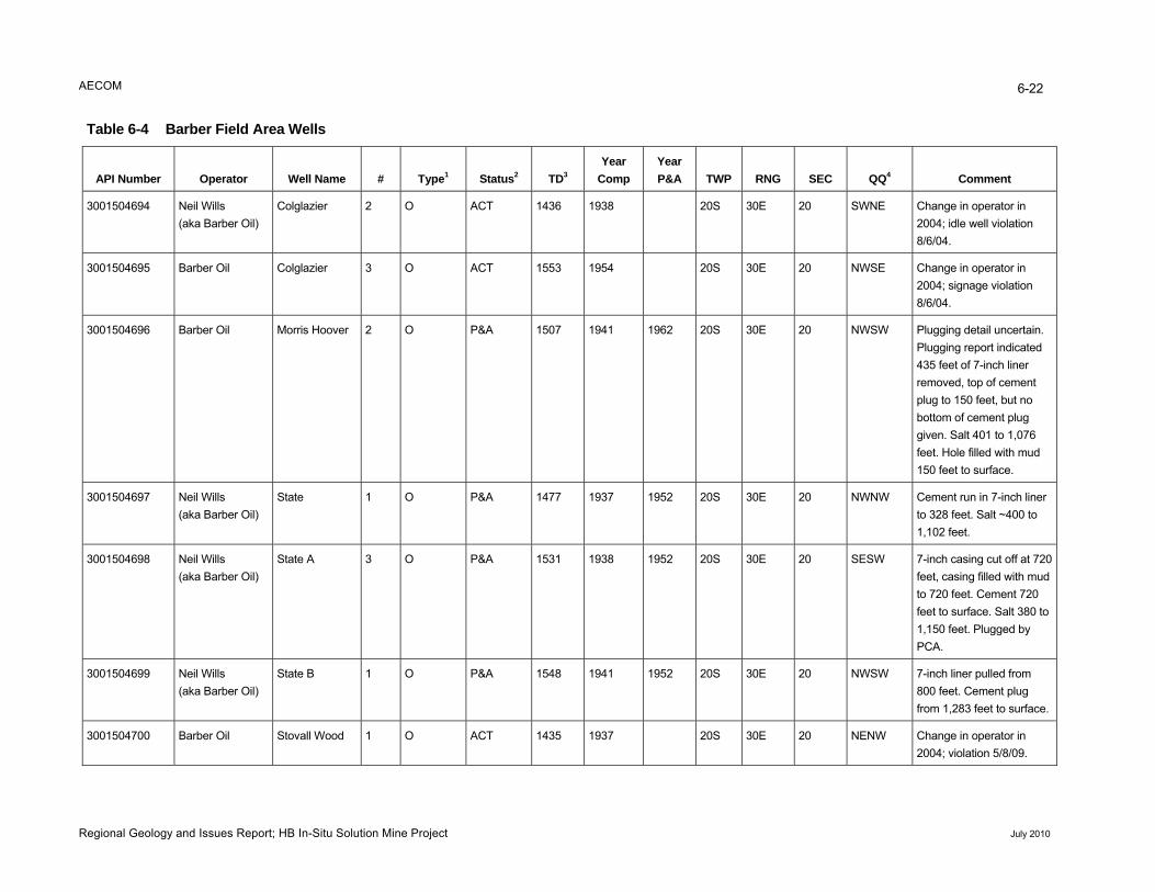
AECOM 6-22
Table 6-4 Barber Field Area Wells
API Number Operator Well Name # Type1 Status2 TD3 Year
Comp Year P&A TWP RNG SEC QQ4 Comment
3001504694 Neil Wills (aka Barber Oil)
Colglazier 2 O ACT 1436 1938 20S 30E 20 SWNE Change in operator in 2004; idle well violation 8/6/04.
3001504695 Barber Oil Colglazier 3 O ACT 1553 1954 20S 30E 20 NWSE Change in operator in 2004; signage violation 8/6/04.
3001504696 Barber Oil Morris Hoover 2 O P&A 1507 1941 1962 20S 30E 20 NWSW Plugging detail uncertain. Plugging report indicated 435 feet of 7-inch liner removed, top of cement plug to 150 feet, but no bottom of cement plug given. Salt 401 to 1,076 feet. Hole filled with mud 150 feet to surface.
3001504697 Neil Wills (aka Barber Oil)
State 1 O P&A 1477 1937 1952 20S 30E 20 NWNW Cement run in 7-inch liner to 328 feet. Salt ~400 to 1,102 feet.
3001504698 Neil Wills State A 3 O P&A 1531 1938 1952 20S 30E 20 SESW 7-inch casing cut off at 720 feet, casing filled with mu(aka Barber Oil) d to 720 feet. Cement 720 feet to surface. Salt 380 to 1,150 feet. Plugged by PCA.
3001504699 Neil Wills State B 1 O P&A 1548 1941 1952 20S 30E 20 NWSW 7-inch liner pulled from (aka Barber Oil) 800 feet. Cement plug
from 1,283 feet to surface.
3001504700 Barber Oil Stovall Wood 1 O ACT 1435 1937 20S 30E 20 NENW Change in operator in 2004; violation 5/8/09.
Regional Geology and Issues Report; HB In-Situ Solution Mine Project July 2010
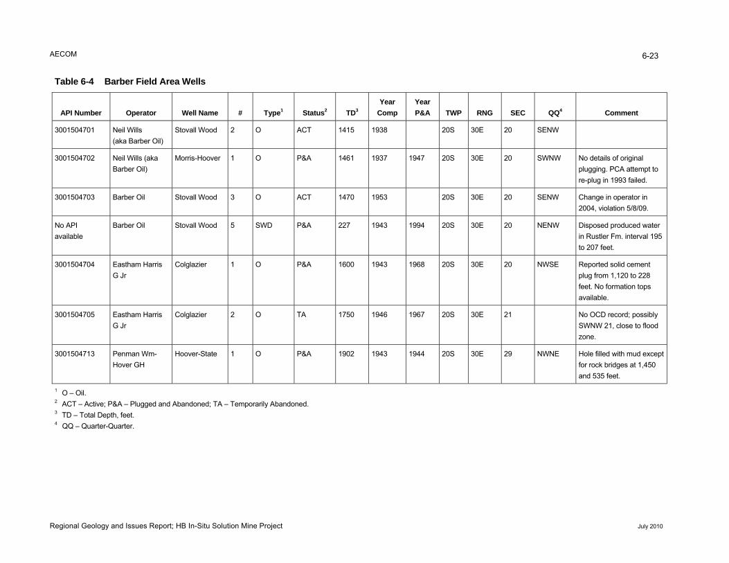
AECOM 6-23
Table 6-4 Barber Field Area Wells
Year Year Type1 Status2 TD3 QQ4 API Number Operator Well Name # Comp P&A TWP RNG SEC Comment
3001504701 Neil Wills (aka Barber Oil)
Stovall Wood 2 O ACT 1415 1938 20S 30E 20 SENW
3001504702 Neil Wills (aka Morris-Hoover 1 O P&A 1461 1937 1947 20S 30E 20 SWNW No details of original Barber Oil) plugging. PCA attempt to
re-plug in 1993 failed.
3001504703 Barber Oil Stovall Wood 3 O ACT 1470 1953 20S 30E 20 SENW Change in operator in 2004, violation 5/8/09.
No API Barber Oil Stovall Wood 5 SWD P&A 227 1943 1994 20S 30E 20 NENW Disposed produced water in Rustler Fm. interval 1available 95 to 207 feet.
3001504704 Eastham Harris Colglazier 1 O P&A 1600 1943 1968 20S 30E 20 NWSE Reported solid cement plug from 1,120 to 228 feet. No formation tops available.
G Jr
3001504705 Eastham Harris G Jr
Colglazier 2 O TA 1750 1946 1967 20S 30E 21 No OCD record; possibly SWNW 21, close to flood zone.
3001504713 Penman Wm-Hover GH
Hoover-State 1 O P&A 1902 1943 1944 20S 30E 29 NWNE Hole filled with mud except for rock bridges at 1,450 and 535 feet.
1 O – Oil. 2 ACT – Active; P&A – Plugged and Abandoned; TA – Temporarily Abandoned. 3 TD – Total Depth, feet. 4 QQ – Quarter-Quarter.
Regional Geology and Issues Report; HB In-Situ Solution Mine Project July 2010
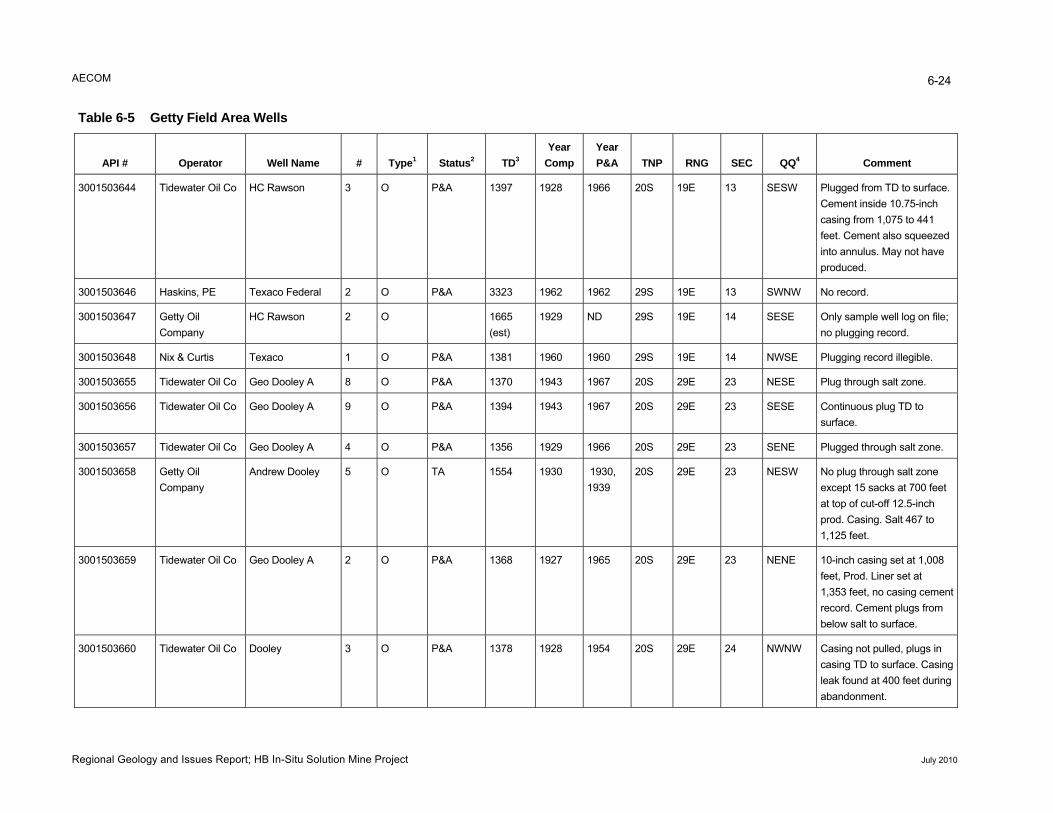
AECOM 6-24
Regional Geology and Issues Report; HB In-Situ Solution Mine Project July 2010
Table 6-5 Getty Field Area Wells
API # Operator Well Name # Type1 Status2 TD3 Year
Comp Year P&A TNP RNG SEC QQ4 Comment
3001503644 Tidewater Oil Co HC Rawson 3 O P&A 1397 1928 1966 20S 19E 13 SESW Plu ged from TD to surface. gCement inside 10.75-inch casing from 1,075 to 441 fee ed t. Cement also squeezinto annulus. May not have produced.
3001503646 Haskins, PE Texaco Federal 2 O P&A 3323 1962 1962 29S 19E 13 SWNW No record.
3001503647 Getty Oil Company
HC Rawson 2 O 1665 (est)
1929 ND 29S 19E 14 SESE Onl ; y sample well log on fileno plugging record.
3001503648 Nix & Curtis Texaco 1 O P&A 1381 1960 1960 29S 19E 14 NWSE Plu illegible. gging record
3001503655 Tidewater Oil Co Geo Dooley A 8 O P&A 1370 1943 1967 20S 29E 23 NESE Plug through salt zone.
3001503656 Tidewater Oil Co Geo Dooley A 9 O P&A 1394 1943 1967 20S 29E 23 SESE Continuous plug TD to surface.
3001503657 Tidewater Oil Co Geo Dooley A 4 O P&A 1356 1929 1966 20S 29E 23 SENE Plugged through salt zone.
3001503658 Getty Oil Company
Andrew Dooley 5 O TA 1554 1930 1930, 1939
20S 29E 23 NESW No plug through salt zone ex sacks at 700 feet cept 15 at top of cut-off 12.5-inch prod. Casing. Salt 467 to 1,125 feet.
3001503659 Tidewater Oil Co Geo Dooley A 2 O P&A 1368 1927 1965 20S 29E 23 NENE 10-inch casing set at 1,008 feet, Prod. Liner set at 1,353 feet, no casing cement record. Cement plugs from below salt to surface.
3001503660 Tidewater Oil Co Dooley 3 O P&A 1378 1928 1954 20S 29E 24 NWNW Casing not pulled, plugs in casing TD to surface. Casing leak found at 400 feet during abandonment.
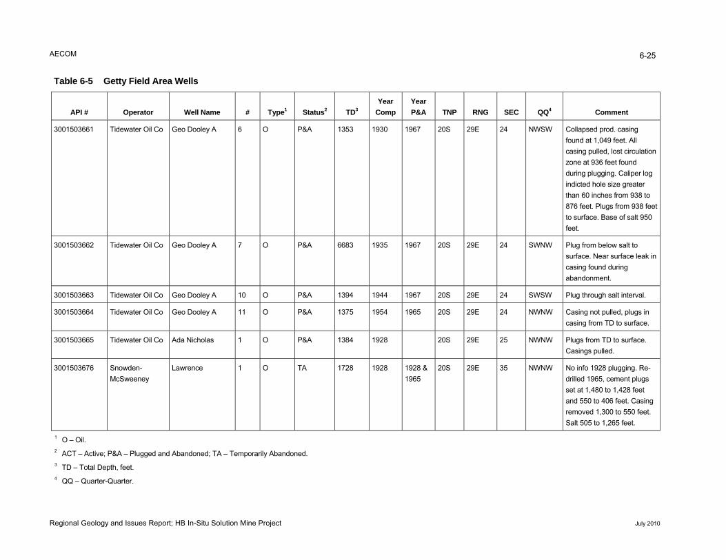
AECOM
Regional Geology and Issues Report; HB In-Situ Solution Mine Project July 2010
6-25
Table 6-5 Getty Field Area Wells
API # Operator Well Name # Type1 Status2 TD3 Year
Comp Year P&A TNP RNG SEC QQ4 Comment
3001503661 Tidewater Oil Co Geo Dooley A 6 O P&A 1353 1930 1967 20S 29E 24 NWSW Collapsed prod. casing found at 1,049 feet. All casing pulled, lost circulation zone at 936 feet found during plugging. Caliper log indicted hole size greater than 60 inches from 938 to 876 feet. Plugs from 938 feet to surface. Base of salt 950 feet.
3001503662 Tidewater Oil Co Geo Dooley A 7 O P&A 6683 1935 1967 20S 29E 24 SWNW Plug from below salt to surface. Near surface leak in casing found during abandonment.
3001503663 Tidewater Oil Co Geo Dooley A 10 O P&A 1394 1944 1967 20S 29E 24 SWSW Plug through salt interval.
3001503664 Tidewater Oil Co Geo Dooley A 11 O P&A 1375 1954 1965 20S 29E 24 NWNW Casing not pulled, plugs in casing from TD to surface.
3001503665 Tidewater Oil Co Ada Nicholas 1 O P&A 1384 1928 20S 29E 25 NWNW Plugs from TD to surface. Casings pulled.
3001503676 Snowden-McSweeney
Lawrence 1 O TA 1728 1928 1928 & 1965
20S 29E 35 NWNW No info 1928 plugging. Re-drilled 1965, cement plugs set at 1,480 to 1,428 feet and 550 to 406 feet. Casing removed 1,300 to 550 feet. Salt 505 to 1,265 feet.
1 O – Oil. 2 ACT – Active; ned; TA – T porar bandoP&A – Plugged and Abando em ily A ned. 3 TD – Total Depth, feet. 4 QQ – Quarter-Quarter.
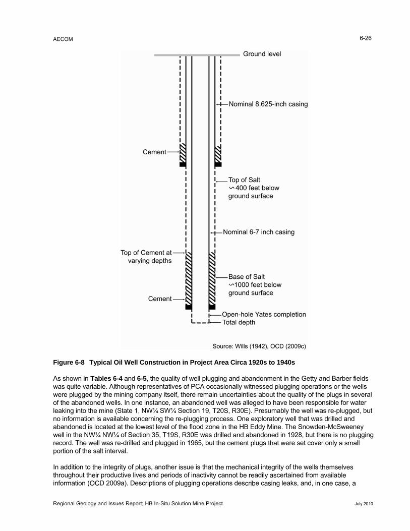
AECOM 6-26
Figure 6-8 Typical Oil Well Construction in Project Area Circa 1920s to 1940s
As shown in les 6-4 and 6-5, the quality of well plugging and a donment in the Getty and Barber fields quite va le. Although representatives of PCA occasionally witnessed plugging operation r the wells plugge the mining company itse ere rema rtain about the quality of the s in several e aband d wells. In one instance, an abandone e as a ed ave been responsible for water ing into t ine (State 1, NW¼ SW¼ Section 19, 30 Presumably the well was lugged, but formatio available concerning the re-plugging . On xploratory well that was d d and doned i cated at the lowest level o e flood zo i e H ddy e Snowden-McSweeney in the N NW¼ of Section 35, T19 30E was ll nd n 1928, but ther gging rd. The w was re-drilled and plugged in 1965, bu e me lugs ere set cover o ll on of the salt interval.
dition to integrity of plugs, anothe ue is tha cha al in rity of the wellsghout th productive lives and perio of inactivi a t b adil certained from
mation ( D 2009a). Descriptions of gging operations des e c g leaks, and, i
Tabriabd byone
ban
tieslleg
was wereof thleakno inabanwell recoporti
In adthrouinfor
s oplug
re-prille
e isnly
msailae c
lf, th in ud w
ncell w to h
he mn iss loW¼
ell
T20procne drit th
S, Ressn thed and ce
E). e eB E abant p
f thS, R
Mine. Thoned i that w
no a s
elveble ase
pluma
s
, a
theeir
OC
r issds plu
t thety c
menno
nice recrib
tegy asasin
the av
n on
Regional Geology and Issues Report; HB In-Situ Solution Mine Project July 2010
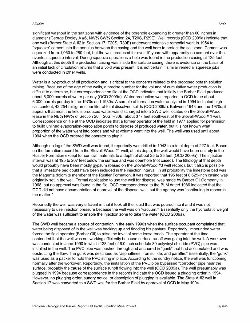
AECOM 6-27
significant washout in the salt zone with evidence of the borehole expanding to greater than 60 inches in diameter (George Dooley A #6, NW¼ SW¼ Section 24, T20S, R29E). Well records (OCD 2009a) indicate that one well (Barber State A #2 in Section 17, T20S, R30E) underwent extensive remedial work in 1954 to “squeeze” cement into the annulus between the casing and the well bore to protect the salt zone. Cement was squeezed from 1,060 to 280 feet, but the well produced for over 10 years with apparently no cement over the eventual squeeze interval. During squeeze operations a hole was found in the production casing at 125 feet. Although at this depth the production casing was inside the surface casing, there is evidence on the basis of an initial lack of circulation returns that a void was present. It is not certain if similar remedial squeeze jobs were conducted in other wells.
Water is a by-product of oil production and is critical to the concerns related to the proposed potash solution mining. Because of the age of the wells, a precise number for the volume of cumulative water production is difficult to determine, but correspondence on file at the OCD indicates that initially the Barber Field produced about 5,000 barrels of water per day (OCD 2009a). Water production was reported to OCD to be about 6,000 barrels per day in the 1970s and 1980s. A sample of formation water analyzed in 1994 indicated high salt content, 42,254 milligrams per liter of total dissolved solids (OCD 2009a). Between 1943 and the 1970s, it appears that most the field’s produced water was discharged into a SWD well located on the Stovall-Wood lease in the NE¼ NW¼ of Section 20, T20S, R30E, about 377 feet southwest of the Stovall-Wood # 1 well. Correspondence on file at the OCD indicates that a former operator of the field in 1977 applied for permission to build unlined evaporation-percolation ponds to dispose of produced water, but it is not known what proportion of the water went into ponds and what volume went into the well. The well was used until about 1994 when the OCD ordered the operator to plug it.
Although no log of the SWD well was found, it reportedly was drilled in 1943 to a total depth of 227 feet. Based on the formation record from the Stovall-Wood #1 well, at this depth, the well would have been entirely in the Rustler Formation except for surficial materials to a depth of about 25 to 35 feet (OCD 2009a). The injection interval was at 195 to 207 feet below the surface and was openhole (not cased). The lithology at that depth would probably have been mostly gypsum (based on the Stovall-Wood #3 well record), but it also is possible that a limestone bed could have been included in the injection interval. In all probability the limestone bed was the Magenta dolomite member of the Rustler Formation. It was reported that 195 feet of 8.625-inch casing was originally set in the well. Formal application to use the well for disposal was made by Barber Oil Company in 1968, but no approval was found in the file. OCD correspondence to the BLM dated 1986 indicated that the OCD did not have documentation of approval of the disposal well, but the agency was “continuing to research the matter.”
Reportedly the well was very efficient in that it took all the liquid that was poured into it and it was not necessary to use injection pressure because the well was on “vacuum.” Essentially only the hydrostatic weight of the water was sufficient to enable the injection zone to take the water (OCD 2009a).
that
g
r, sundry notice, or description of plugging is available. The State A #2 well in
The SWD well became a source of contention in the early 1990s when the surface occupant complained water being disposed of in the well was backing up and flooding his pasture. Reportedly, impounded water forced the field operator (Barber Oil) to raise the level of some lease roads. The operator at the time contended that the well was not working efficiently because surface runoff was going into the well. A workover was conducted in June 1990 in which 128 feet of 6.0-inch schedule 80 polyvinyl chloride (PVC) pipe was installed in the well. The PVC pipe was pushed through and anchored in “gunk” that had accumulated and was obstructing the flow. The gunk was described as “asphaltines, iron sulfide, and paraffin.” Essentially, the “gunk” was used as a packer to hold the PVC string in place. According to the sundry notice, the well was functioninnormally after the workover. Reportedly, the installation of the PVC pipe bypassed “corroded” pipe near the surface, probably the cause of the surface runoff flowing into the well (OCD 2009a). The well presumably was plugged in 1994 because correspondence in the records indicate the OCD issued a plugging order in 1994. However, no plugging ordeSection 17 was converted to a SWD well for the Barber Field by approval of OCD in May 1994.
Regional Geology and Issues Report; HB In-Situ Solution Mine Project July 2010
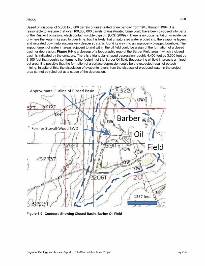
AECOM
Regional Geology and Issues Report; HB In-Situ Solution Mine Project July 2010
6-28
idence
by to the footprint of the Barber Oil field. Because the oil field intersects a mined-
out area, it is possible that the formation of a surface depression could be the expected result of potash
Based on disposal of 5,000 to 6,000 barrels of unsaturated brine per day from 1943 through 1994, it is reasonable to assume that over 100,000,000 barrels of unsaturated brine could have been disposed into parts of the Rustler Formation, which contain soluble gypsum (OCD 2009a). There is no documentation or evof where the water migrated to over time, but it is likely that unsaturated water eroded into the evaporite layers and migrated down into successively deeper strata, or found its way into an improperly plugged borehole. Theimpoundment of water in areas adjacent to and within the oil field could be a sign of the formation of a closed basin or depression. Figure 6-9 is a closeup of a topographic map of the Barber Field area in which a closed basin is indicated by the contours. There is a triangular-shaped depression roughly 4,400 feet by 3,300 feet3,100 feet that roughly conforms
mining. In spite of this, the dissolution of evaporite layers from the disposal of produced water in the project area cannot be ruled out as a cause of the depression.
Figure 6-9 Contours Showing Closed Basin, Barber Oil Field
AECOM 7-1
nderground potash mining has occurred in the project area for more than 70 years. Subsidence occurred as a result of the removal of potash ore, but because of the rural nature of the area and the thickness of ore extracted, the effects of subsidence appear to be minor and limited. However, the effect of subsidence on surface water runoff and groundwater flow is not known. The known amount of subsidence due to historical mining is estimated to be approximately 1.0 to 1.5 feet (Intrepid Potash/Shaw 2008a).
The severity of mining subsidence is dependent on a number of factors including height of mine opening, width of the mined-out void, the depth of the void, and the nature of the overburden. The effects of subsidence can occur beyond the limits of mining due to tensional forces. These forces are propagated through the overburden and are manifested on the surface as tension cracks. The ability of voids to reach the surface is limited by the bulking of broken material causing the collapsed material to fill the void and support the top of the void space.
Historical subsidence in the project area was calculated by USP (predecessor to Intrepid Potash) to be around 4.2 feet, given a nominal mined thickness of 6 feet. This assumes the mining of only one ore zone and does not take into account the mining of multiple zones. However, there appears to have been limited mining of zones other than the primary or first ore zone (Intrepid Potash/Shaw 2008a). The subsidence appears on the surface as wide shallow troughs bounded by tension cracks. Fractures have been documented in several areas, but due to the abundance of unconsolidated surface material over the mining areas, fractures on the surface have probably not been readily observed or were easily eroded and obscured. The impoundment of runoff in the vicinity of the Barber Field may be evidence of trough formation, but it may have other causes related to oil and gas production. There may be other areas over the mines where similar impounding of runoff has occurred, but no observational information was available. The cause of the formation of a sinkhole in the vicinity of the HB North Mine was not linked to mining subsidence (Cranston 2010), but cannot be overlooked.
There is no information readily available regarding the effects of mining subsidence on surface structures, oil wells (active or abandoned), or pipelines in the project area. It is possible that some of the remaining production wells in the Barber Field outside the proposed flood zone could be subjected to tensional stresses generated by subsidence from solution mining because the stresses can occur beyond the boundary of mining. It is not possible to predict what effects may occur to the wells and casings that may be over 50 years old.
It is likely that most subsidence from historical mining has already occurred and that no additional substantial dence effects may occur as a result of
solution mining. However, Intrepid Potash (Intrepid Potash/Shaw 2008a) estimated that the surface effects of olution mining would result in only around 0.5 to 1.0 foot of subsidence, and there is no information available
that would lead to an assumption that subsidence would be greater (see Section 6.2.2.3).
Solution potash mining is not expected to create large, relatively shallow underground voids such as those associated with brine mining. There is small potential for catastrophic subsidence incidents similar to those that occurred in Eddy County in 2008 because the proposed method does not lead to the creation of large
7.0 Summary and Conclusions
The preceding sections described the environmental geologic conditions in the area where Intrepid Potash proposes to conduct solution mining to maximize recovery of potash resource from previously mined areas. The results of this study indicate several concerns and issues that require further consideration in the analysisof potential impacts from solution mining. Those concerns involve potential subsidence of the ground surface resulting from potash mining and the presence of oil wells adjacent to or within areas proposed for flooding. This section summarizes those concerns and makes recommendations on how to minimize their potential effects.
7.1 Subsidence and Potash Mining
U
subsidence would be expected. It is possible that incremental subsi
s
Regional Geology and Issues Report; HB In-Situ Solution Mine Project July 2010

AECOM 7-2
would not be totally dissolved, they would be able to
• Oil production wells in the Getty and Barber fields were originally drilled from the 1920s to the 1950s ral decades.
as its,
others
respect to salt minerals and there is a lack of cemented casing throughout the salt interval, it is very likely that fluids have dissolved and eroded salt behind the pipes. Evidence
,
o
Witness of plugging or plugging by mine personnel would not necessarily guarantee success of the plugging
rns.
• There are no data regarding where the water went, the potential extent of solution of evaporite layers,
the dissolution of
cavities. In addition, because the pillars or debris piles provide partial support for the overburden.
7.2 Oil and Gas Production and Proposed Solution Mining
The historic and present-day production of oil and gas in the proposed solution mining areas poses a number of concerns related to well integrity in active and abandoned wells. However, the disposal of oil field produced water in shallow zones above the salt mine workings presents unique concerns.
The following is a summary of observations regarding well integrity and adequacy of plugging:
and were active producers for seve
• Well construction documentation indicates that the wells did not have adequate cement in the annular space between production casings or liners and salt formations. It is possible that remedial work wdone to squeeze cement into the annular space between casing and borehole to protect the salt unbut data on the adequacy of this procedure for all wells are not available.
• In the Barber Field, eight wells are still active, one having been converted to a SWD well. Thewere primarily abandoned in the 1950s and 1960s. There is little information on well integrity for those wells that were abandoned in that time period, except for evidence of casing leaks or collapse that were found when the casing strings were removed. However, if abandonment descriptions do not describe casing leaks, it does not mean that leaks did not exist.
• Given the corrosive nature of the produced water, corrosion of casings is a certainty. Because the water is unsaturated with
of solution was provided by the borehole diameter greater than 60 inches upon removal of casing in one well that was undergoing abandonment (Table 6-5; George Dooley A #6, NW¼ SW¼ Section 24T20S, R29E).
• Although a 1938 observation indicated evidence of a hydraulic head at least 450 feet above the oil zone, 70 years of production would have undoubtedly resulted in under-pressured conditions existingin the Yates production zone.
• A plugged exploratory well was thought by mine personnel to have contributed to migration of fluid tthe mining level, but no re-plugging record was available (State #1, NW¼ SW¼ Section 19, T20S, R30E).
job (Morris Hoover #1 SW¼ NW¼ Section 20, T20S, R30E).
The existence of a SWD well at Barber Field that was used to dispose of an estimated 100,000,000 or more barrels of unsaturated produced water into a shallow zone in the Rustler Formation poses serious conceThose concerns are as follows:
and whether a void has been created in the subsurface underneath the oil field.
• Evidence of the impoundment of surface water runoff in the vicinity of the oil field may indicate that subsidence has occurred or is occurring, but the cause of the backup of runoff is not known. The USGS topographic map of the area clearly shows a closed basin that essentially coincides with the Barber Oil field. If the cause is subsidence, it could either be the result of mining orevaporite beds. Impoundment of surface water runoff is often a warning or precursor to the development of a sinkhole (Dunrud and Nevins 1981).
Regional Geology and Issues Report; HB In-Situ Solution Mine Project July 2010
AECOM 7-3
improperly plugged well or solution cavities created by
uncontrolled disposed water.
compromised, upward flow e
draulic head to
The llorelated t
• h should continue its planned subsidence monitoring program and subsidence
sh/Shaw 2008a).
jection and extraction system (Intrepid Potash/Shaw
• It is not unreasonable to assume that the disposed oil field water could have reached the potash orelevels through a conduit such as an
The implications of the observations listed above for the proposed solution mining of potash are listed as follows:
• It has been asserted that if the integrity of the abandoned wells would be from the Yates would prevent in-situ brine mining water from flowing into an abandoned well bor(Schowengerdt 2009). Given the 70 or more years of oil production, there is likely no hyprevent fluids from migrating down from a potash flood zone, either through an improperly plugged well or through active wells that are in communication with the salt section.
• All wells in or near the flood zone should be cause for concern as a source of the unintentional migration of fluids, not just the wells in the flood zone. A “good plug” might not be of much value if during the well’s operational life, communication to the salt section was accomplished through lack of maintenance and casing corrosion.
• In abandoned wells where drilling mud was mud left in place and cement plugs were either placed over short intervals or not placed at all, the mud and short plugs may not provide an adequate seal to prevent migration of fluids.
• Because of uncertainties related to operational well integrity and proper plugging, the reported 100-foot barrier pillars that were left around oil wells do not guarantee that these pillars would provideadequate protection against the migration of fluids. No information has been provided by Intrepid Potash that addresses the current condition of the pillars.
A produced water disposal zone located above the salt layer may adversely affect the ability to conduct solution mining successfully and for surface stability and surface use by oil field surface facilities and solution mining infrastructure.
7.3 Recommendations
7.3.1 Recommendations Concerning Solution Potash Mining
fo wing items are recommended actions that could be taken by Intrepid Potash to lessen the risks o past mining and proposed in-situ solution mining.
Intrepid Potasmonitoring transects described in Section 6.2.2.3. Several sets of measurements at regular intervals (monthly or quarterly) should begin prior to the start of solution mining to establish a baseline and to determine if subsidence is still occurring (Intrepid Pota
The injection and extraction wells for the proposed solution mining are located in places vulnerable to stressesin the overburden due to subsidence. It is possible that such stresses could potentially damage wells. IntrepidPotash provided a compliance monitoring plan for the in2008a), but did not provide details on which monitored parameters would specifically address the potential for well damage. It is recommended that Intrepid Potash provide such information or amend the monitoring plan to account for potential well damage.
Regional Geology and Issues Report; HB In-Situ Solution Mine Project July 2010
AECOM
Regional Geology and Issues Report; HB In-Situ Solution Mine Project July 2010
7-4
7.3.
The follo of the concerns related to
zones) in HB South and Eddy mines should undergo a thorough due diligence evaluation based on
assessment should n of
ity. If
in compliance with OCD Order R-111-P.
lish
d to be too high-risk based on the due diligence evaluations, and, if potential are cost prohibitive, then an alternative of no solution mining should be
ent.
2 Recommendations Concerning Oil and Gas Activities
wing items are recommended actions that could be taken by Intrepid Potash to lessen the risks oil field activities:
• All wells, whether active or abandoned, that penetrate the mined zones (not just the proposed flood
available information. Available information should include review of hard-copy files as may exist at the OCD and BLM’s Carlsbad, New Mexico offices. Due diligence should include interviews with representatives of the current operator and with persons who may have direct knowledge of historic operations, assuming such individuals are still living and competent to be interviewed. Records of the current operator should be reviewed if available. The evaluation should include a hard look at all plugging descriptions and include an assessment of the quality of plugging. The include an assignment of risk to each well as to the susceptibility to act as a conduit for migratiofluids from any source. The due diligence assessment should be conducted by an independent petroleum engineer or petroleum geologist with a strong background in casing and cementing conditions in the Delaware Basin.
• If certain wells are deemed high risk due to poor plugging or evidence of casing integrity problems when the wells were operational, re-drilling and re-plugging through the salt interval should be accomplished according to OCD Order R-111-P.
• With consent of the operators, active wells in the Barber Field should be tested for casing integrthis is cost prohibitive, then serious consideration should be given to abandoning the wells, with reasonable compensation paid to the operator. It is likely that the field is close to the end of commercial viability. Abandonment would be accomplished
• As soon as possible, Intrepid Potash should conduct surveys, geophysical or otherwise, to estabwhether or not voids are present in the shallow subsurface in the vicinity of the former shallow disposal well.
If solution mining is determineremedial work and monitoringconsidered for the HB South mine in the environmental impact statem
AECOM 8-1
8.0 References
Adams. E. A, M. G. Cheney, R. K. DeFord, R. I. Dickey, C. O. Dunbar, J. M. Hills, R. E. King, E. R. Lloyd, A. K.
6 p.
’s
.
Group of West TeS .
British D e Environment – Welsh Office. 1990. Planning Policy Guidance – Development of
roadhead, R. F., Z. Jianhua, and W. D. Raatz. 2004. Play Analysis of Major Oil Reservoirs in the New Mexico Part of the Permian Basin: Enhanced Production Through Advanced Technologies: New Mexico Bureau of Geology and Mineral Resources, Open File Report 479, July 2004, 135 p.
Calzia, J. P. and W. L. Hiss. 1978. Igneous Rocks in Northern Delaware Basin, New Mexico and Texas, in Austin, G.S. (compiler), Geology and Mineral Deposits of Ochoan Rocks in Delaware Basin and Adjacent Areas, New Mexico Bureau of Mines and Mineral Resources Circular 159, p. 30-45.
Cearley, J. D. 2000. Early West Texas Drilling and Formation Evaluation Technology: American Association of Petroleum Geologists southwest Section 2000 Proceedings. Internet website: www.barnettshale.us/
Miller, and C. E. Needham. 1939. Standard Permian Section of North America: Bulletin American Association of Petroleum Geologists; Vol. 23. No. 11 (November). p. 1673-1681.
American Geological Institute. 1997. Dictionary of Mining, Mineral, and Related Terms, second edition, 64
Bachman, G. O. 1983. Regional Geology of the Ochoan Evaporites, Northern Part of the Delaware Basin: NewMexico Bureau of Mines and Mineral Resources Open File Report 184, May 1983, 56 p.
Balch, R. S., M. Cather, and V. Bammidi. 2009. Oil and Gas Potential Analysis of the Secretary of the InteriorPotash Area, Southeastern New Mexico, Petroleum Recovery Research Center Report 09-07 NewMexico Tech November 13, 2009, 32 p.
Barker, J., I. Gundiler, and P. Walsh. 2008. New Mexico Potash – Past, Present, and Future: New Mexico Earth Matters, Summer 2008, New Mexico Bureau of Mines and Bureau of Geology and Mineral Resources, p. 1-3.
Baum, R. L., D. L. Galloway, and E. L. Harp. 2008. Landslide and Land Subsidence Hazards to Pipelines. U.SGeological Survey Open-File Report 2008–1164, 202 p.
Berg, R. R. 1979. Reservoir Sandstone of the Delaware Mountain Group in Guadalupian Delaware Mountain xas and Southeast New Mexico, Symposium and Field Conference Guidebook,
ociety of Economic Mineralogists and Paleontologists Permian Basin Section, Publication 79-18, p. 95
epartment of thUnstable Land.
British National Coal Board – Mining Division. 1975. Subsidence Engineers Handbook.
B
. Accessed December 17, 2009.
Cheesemen, R. J. 1978. Geology and Oil/Potash Resources Delaware Basin, Eddy and Lea Counties, New Mexico in Austin, G.S. (compiler), Geology and Mineral Deposits of Ochoan Rocks in Delaware Basin and Adjacent Areas, New Mexico Bureau of Mines and Mineral Resources Circular 159, p. 7-14.
Cranston, C. 2010. Mining Engineer, Carlsbad BLM Field Office personal communication to AECOM. May 10, 2010.
Dane, C. H. and G. O. Bachman. 1958. Preliminary Geologic Map of the Southeastern Part of New Mexico: USGS Survey Miscellaneous Geologic Investigations Map I-256, scale 1:380,160.
Regional Geology and Issues Report; HB In-Situ Solution Mine Project July 2010
AECOM 8-2
Characteristics of a Deep-Seated Dissolution-Subsidence Chimney in Bedded l Symposium on Salt Volume 1, p.331-350.
Dunru ks in the United
Oil
rg
s/ocd/brinewells.htm
Davies, P. B. 1983. Structural Salt. Sixth Internationa
Davis, S. 2009. Carlsbad’s Earliest Potash-Mining Facilities Being Salvaged: Pay Dirt Magazine, June 2009, p. 9-10. Reprinted from the Carlsbad Current-Argus.
d, D. R. and B. B. Nevins. 1981. Solution Mining and Subsidence in Evaporite RocStates. U.S. Geological Survey Miscellaneous Investigations Series I-1298.
Federal Register. 1986. Oil, Gas and Potash Leasing and Development Within the Designated Potash Area of Eddy and Lea Counties, New Mexico. Vol. 51, No. 208. Department of the Interior, Office of the Secretary. October 28.
Fenneman, N. M. 1928. Physiographic Divisions of the United States: Annals of the Association of American Geographers, Vol. 18, No. 4, (Dec., 1928), pp. 261-353.
Giroux, R. L., J. T Brandell, and T. A. Scott. 1988. Annulus Packoff System Provides Economy in Recompletion of Permian Basin Wells (SPE 17298): Society of Petroleum Engineers Permian basin and Gas Recovery Conference, Midland, Texas, March 10-11, 1988, p. 267-272.
Golder and Associates. 1979. Report to USDOI and USGS on Recommendations on Abandonment of the Will-Weaver Mine and Shafts. Prepared for the U.S. Geological Survey by Golder and Associates, November 1979.
Goodbar, J. 2010. Cave and Karst Specialist, BLM Carlsbad, New Mexico; personal communication with AECOM. February 8, 2010.
Griswold, J. 2010. New Mexico Oil Conservation Brine Mining Supevisor personal communication to Bill Beof AECOM, may 11, 2010.
Griswald, J. 2009. Brine Well Information. Internet website: http://www.emnrd.state.nm.u . Accessed December 23, 2009.
Hayes, P. T. 1964. Geology of the Guadalupe Mountains, New Mexico. USGS Professional Paper 446. Internet website: http://www.nps.gov/history/history/online_books/cave/446/contents.htm. Accessed November 30, 2009.
Hill, C. A. 2003. Intrastratal Karst at the Waste Isolation Pilot Plant Site, Southeastern New Mexico, In: Johnson, K. S. and J. T. Neal (editors), Evaporite-karst and Engineering/Environmental Problems in United States, Oklahoma Geological Survey Circular 109, p. 1-20.
the
est
Hill, C. A. 1996. Geology of the Delaware Basin, Guadalupe, Apache, and Glass Mountains: Permian Basin Section of the Society of Economic Paleontologists and Mineralogists Publication No. 96-39, 479 p.
Hunter, B., F. Tahmourpour, and R. Faul. 2009. Cementing Casing Strings Across Salt Zones: An Overview of Global Best Practices (SPE 122079). Presented at the 2009 Society of Petroleum Engineers Asia Pacific Oil and Gas Conference and Exhibition, Jakarta, Indonesia, 4-6 August, 2009, 12 p.
Independent Petroleum Association of New Mexico. Undated. History New Mexico Oil and Gas: Northwand Southeast. Internet website: http://www.ipanm.org/index.php?option=com_content&view= article&id=21&Itemid=19. Accessed December 21, 2009.
Regional Geology and Issues Report; HB In-Situ Solution Mine Project July 2010
AECOM 8-3
Management Carlsbad Field Office, Carlsbad, New Mexico. Prepared by Shaw Environmental and Infrastructure, Inc.
Intrep ssment of Petroleum Wells within the Flood Zone, Tech Memo HB Potash EA-003 HB In-situ Project, HB Potash LLC, Eddy County, New Mexico;
Intrepid Potash/Shaw. 2008c. Technical Memorandum: Reviewed Subsidence Associated with Potash Mining;
Intrepid Potash/Shaw. 2008d. Technical Memorandum: Subsidence Overview Tech Memo HB Potash DP-
otash DP-
Infrastructure, Inc.
Johnson, K. S. 2005. Subsidence Hazards Due to Evaporite Dissolution in the United States Environ Geol
Johnson, K. S., E. W. Collins, and S. J. Seni. 2003. Sinkholes and Land Subsidence owing to Salt Dissolution
Intrepid Potash/Shaw. 2008a. Mine Operations and Closure Plan HB In-situ Project, HB Potash LLC, Eddy County, New Mexico, May 28, 2008. Submitted to: Bureau of Land
id Potash/Shaw. 2008b. Technical Memorandum: Asse
December 17, 2008. Prepared by Shaw Environmental and Infrastructure, Inc.
Tech Memo HB Potash EA-004, HB Potash LLC, Eddy County, New Mexico; December 17, 2008. Prepared by Shaw Environmental and Infrastructure, Inc.
006. HB Potash LLC, Eddy County New Mexico, September 29, 2008. Prepared by Shaw Environmental and Infrastructure, Inc.
Intrepid Potash/Shaw. 2008e. Technical Memorandum: Subsidence Monitoring; Tech Memo HB P003, HB Potash LLC, Eddy County, New Mexico; September 29, 2008. Prepared by Shaw Environmental and Infrastructure, Inc.
Intrepid Potash/Shaw. 2008f. Technical Memorandum: Subsidence Overview; Tech Memo HB Potash DP-006, HB Potash LLC, Eddy County, New Mexico; September 29, 2008. Prepared by Shaw Environmental and
Jaeger, J. C. and N. G. W. Cook. 1976. Fundamentals or Rock Mechanics; Halstead Press; 1976.
(2005) 48: 395–409 DOI 10.1007/s00254-005-1283-5, p.395 to 409.
Near Wink, Texas, and Other Sites in Western Texas and New Mexico, In: Johnson, K. S. and J. T. Neal (editors), Evaporite-karst and Engineering/Environmental Problems in the United States, Oklahoma Geological Survey Circular 109, p. 183-195.
Kastnt: Common Problems and Educational Solutions, in Rea, G. (ed) Proceedings of
the 1999 Cave and Karst Management Symposium, Chattanooga, Tennessee, October 19-20, 1999;
ing, E. H., K. M. Kastning, and Virginia Department of Environmental Quality. 2001. Misconceptions About Caves and Kars
Southeastern Cave Conservancy, Inc.; p. 94-107. Internet website: http://www.nckms.org/99proceed.html. Accessed November 30, 2009.
Kern, J. V. 1984. You and U. S. Potash 1925-1968. United States Borax and Chemical Corporation, Los
LaFleur, K. K. and W. P Lovelace. 1969. Brine Deterioration of Cement and a Replacement Cementing
Lambert, S. J. 1983. Dissolution of Evaporites in and Around the Delaware Basin, Southeastern New Mexico
Loren ustler Formation at the WIPP Site Sandia Report SAND2005-7303 unlimited release. Printed January 2006, 103 p.
Angeles, California,
Technique (SPE 2454). Prepared for the Rocky Mountain Regional Meeting of the Society of Petroleum Engineers, Denver, Colorado, May 26-27, 1969, 8p.
and West Texas. Sandia National Laboratories, Albuquerque, New Mexico, 96 p.
z, J. C. 2006. Assessment of the Potential for Karst in the R
Regional Geology and Issues Report; HB In-Situ Solution Mine Project July 2010
AECOM 8-4
), p. 1901-1926.
st
Montgomery, R. F. 1965. The Oil and Gas Resources of Southeastern New Mexico in USGS, 1965, Mineraland Water Resources of New Mexico: New Mexico Bureau of Mines & Mineral Resources Bulletin No. 87, p. 74-86.
Montgomery, S. L., J. Worrall, and D. Hamilton. 1999. Delaware Mountain Group, West Texas and Southeastern New Mexico, A Case of Refound Opportunity: Part 1—Brushy Canyon: American Association of Petroleum Geologists Bulletin volume 83, Number 12 (December
Muller, S. C. and R. Galyen. 2009. Polyhalite Resources and a Preliminary Economic Assessment of the Ochoa Project Lea County, Southeast New Mexico. Prepared for Trigon Uranium Corporation, Augu19, 2009, 258 p.
Oil Conservation Division (OCD). 2009a. Online Database. Internet website: http://www.emnrd.state.nm.us/ocd/ OCDOnline.htm. Accessed December 17, 2009.
Oil Conservation Division (OCD). 2009b. Brine Well Information. Internet website: http://www.emnrd.state.nm.us/ OCD/brinewells.htm. Accessed December 17, 2009.
nservation Division (OCD). 2009c. WelOil Co l Bore Diagrams for Wells in the Potash Area.
ine exico.
exico: The American Association of Petroleum Geologists Bulletin volume 60. No. 4 (April p. 517-527.
Powe issolution, Drill Holes, and the Potential for Sinkhole Development; in Johnson, K. S.; and J. T. Neal, editors, Evaporite Karst and
Remp ansen, and C. T. Franke. 1999. Geotechnical Perspectives on the Waste Isolation Pilot Plant. Sandia National Laboratories.
Roche
ccessed November 23, 2009.
. covered oil and gas resources of the Permian Basin Province of west Texas
and southeast New Mexico, 2007, U.S. Geological Survey Fact Sheet 2007–3115, 4 p.
Schow09.
.
.
Palacas, J.G., R. P. Snyder, J. P. Baysinger, and C. N. Threlkeld. 1982. Geochemical Analysis of Potash MSeep Oils, Collapsed Breccia Pipe Oil Shows and Selected Crude Oils, Eddy County, New MUSGS Open File Report 82-421, 41 p.
Payne, M. W. 1976. Basinal Sandstone Facies, Delaware Basin, West Texas and Southeast New M
rs, D. W. 2003. Jal Sinkhole in Southeastern New Mexico: Evaporite D
Engineering/Environmental Problems in the United States: Oklahoma Geological Survey Circular 109, p. 219-226.
e, N. T., S. J. Patchet, M. K. Knowles, F. D. H
, S. L. 1997. Time-lapse Multicomponent, Three-Dimensional Seismic Characterization of a San Andres Shelf Carbonate Reservoir, Vacuum Field, Lea County, New Mexico. Unpublished Ph.D dissertation Colorado School of Mines. Available at http://geophysics.mines.edu/rcp/theses/old/Roche_1997/slrchp2.html. A
Schenk, C. J., R. M. Pollastro, T. A. Cook, M. J. Pawlewicz, T. R. Klett, R. R. Charpentier, and H. E. Cook2008. Assessment of undis
engerdt, R. 2009. Principal Engineer and Hydrogeologist, Shaw Environmental and Infrastructure, personal communication to AECOM September 14, 20
Sisselman, R. (ed). 1978. Mining Tabular Carlsbad Deposits. E/MJ Operating Handbook of Mineral Underground Mining. Volume 3-E/MJ Library of Operating Handbooks, p. 409-412
Smith, D.K. 1976. Cementing. Society of Petroleum Engineers of AIME, Monograph Volume 4 of the Henry LDougherty Series, 184 p.
Regional Geology and Issues Report; HB In-Situ Solution Mine Project July 2010
AECOM
Regional Geology and Issues Report; HB In-Situ Solution Mine Project July 2010
8-5
Southwest Region National Speleological Society. 1991. New Mexico Gypsum Karst Project (GYPKAP)
Trimb rinted from the U.S. Geological Survey Bulletin 1493, published in 1980; 54 p.
Unitedbsite: http://minerals.usgs.gov/minerals/pubs/state/nm.html
Snyder, R. P. and L. M. Gard. 1982. Evaluation of Breccia Pipes in Southeastern New Mexico and Their Relationship to the Waste Isolation Pilot Plant (WIPP) Site. USGS Open File Report 82-968, 78 p.
Report #2, January 1988 to December 1991.
le, D.E. 1990. The Geologic Story of the Great Plains. Theodore Roosevelt History Association, rep
States Geological Survey (USGS). 2009. Minerals Yearbook: The Mineral Industry in New Mexico 2006. Internet we . Accessed December 4, 2009.
United c Names (Geolex) Database. Internet website http://ngmdb.usgs.gov/Geolex/NewUnits/unit_13938.html States Geological Survey (USGS). 2007. National Geologic Map Database: Geologi
. Modified
Van Sambeek. 2008. HB Project Surface Subsidence (Revised). Technical Memorandum from Dr. Leo L. Van a, Carlbad, New
Mexico., December 15, 2008.
Vine,
f
Walters, R. F. 1978. Land Subsidence in Central Kansas related to Salt Dissolution. Bulletin 214, Kansas
Williams-Stroud, S., J.P Searls, and R.J. Hite. 1994. Potash Resources, in Industrial Minerals and Rocks, 6th
Wills, er); Oil and Gas Resources of New Mexico, New
January 7, 2007. Accessed November 24, 2009.
Sambeek to Mr. Craig Cranston, Bureau of Land Management, Carllbad Resource Are
J. D. 1963. The Geology of Nash Draw, Eddy County, New Mexico: U.S. Geological Survey Bulletin 1141-B, 46 p.
Vine, J. D. 1960. Recent Domal Structures in Southeast New Mexico: American Association of Petroleum Geologists Bulletin Vol. 44, No. 12 (December), p. 1903-1911.
Walsh, P. 2006. Geologic trends of oil and gas production in the Secretary of the Interior’s Potash Area, Southeastern New Mexico, Final Report to the Bureau of Land Management, New Mexico Bureau oGeology and Mineral Resources Open File Report 498, 51 p.
Geological Survey, Lawrence, Kansas, 87 p.
Edition, Society for Mining, Metallurgy, and Exploration, Inc., p. 783 802.
N. 1942. Getty-Barber Area in Bates, R.L. (compilMexico School of Mines, State Bureau of Mines and Mineral Resources, Bulletin No. 18., p. 174-179.
World Climate. 2009. Carlsbad, Eddy County, New Mexico, Weather History and Climate Data. Internet website: http://www.worldclimate.com/cgi-bin/grid.pl?gr=N32W104. Accessed November 17, 2009.
AECOM 9-1
9.0
Anhyd with minerals gypsum and
w
Brecc ngular fragments. Breccias can be formed by a
Evapo applied to sedimentary rocks that result from the evaporation of
Carbo of either calcite or dolomite. This term
Clasti cks.
tation and recrystallization
Halite
Inactiv
arst Any region underlain by evaporites and characterized by land-forms resulting from carbonation and dissolution of the rocks by fluvial processes. Common landforms include, but are not limited to: springs, caves, sinkholes, and disappearing and reappearing streams.
Mine Any and all parts of the property of the mining plant, either on the surface or underground, that contribute directly or indirectly to the mining or handling of ore.
Mine Workings Areas that have been or are being mined.
Glossary
Abandoned Workings Excavations that have either caved-in or have been sealed,
Active Workings All places in a mine that are ventilated and inspected regularly.
rite Rock forming, evaporite mineral that commonly occurshalite. Can be formed by deposition from seawater, and dehydration of gypsum. May occur as a cap-rock above salt domes or in hydrothermal veins. Used as a ramaterial in cement.
Annulus The space around the outside of a pipe suspended in a borehole. The space can be either between the pipe and the wall of the borehole or another string of pipe.
ia A sedimentary rock containing avariety of processes, but the breccias discussed in this report are formed by the collapse of subsurface voids that result from the dissolution of evaporite deposits.
rite General termbodies of surficial water. Common rock types include limestone, dolomite, anhydrite, gypsum and salt.
Facies A rock unit with specific features and characteristics that reflect the specific environmental conditions and processes under which the rock was formed or deposited.
Fluvial Processes involving rivers or streams.
nate Sedimentary rocks with 95 percent or moremay is commonly synonymous with limestone.
c Fragmented sedimentary ro
Diagenetic Changes that take place in a sediment at low temperature and pressure after deposition. Processes may include compaction, cemenand are the means by which sediment is turned into sedimentary rock.
Rock salt. Sodium Chloride. Widely distributed in stratified evaporite deposits and associated with other water soluble minerals including gypsum and anhydrite.
e Workings Previously mined areas not currently being mined, ventilated or inspected.
K
Regional Geology and Issues Report; HB In-Situ Solution Mine Project July 2010
AECOM
Regional Geology and Issues Report; HB In-Situ Solution Mine Project July 2010
9-2
The void spaces within a rock. Porosity is expressed as a percentage of the bulk volume of a rock. Not all void spaces are interconnected and able to transmit fluids. The effective porosity of a rock refers to the proportion of interconnected pores and
the rock and d an epoch. A
Sinkhole
Squeeze
Turbidite owing g as a result of density differences between dispersed
y
Turbidity flow nt of sediment under the influence of gravity in a turbulent flow of
Vuggy porosity paces are formed by solution vugs.
r isting production well for the purpose of restoring, ive
Porosity
its ability to transmit fluids.
Series Series are subdivisions of rock layers made based on the age ofcorresponding to the geologic time scale dating system unit calleseries denotes the layers of strata or a body of rock deposited during one epoch.
Steep sided enclosed depression, found commonly in a limestone or karst region. Commonly enlarged over time by solution (carbonation) and by collapse.
Solution A weathering process by which water molecules bond with and detach ionic components of minerals. Commonly the first stage of chemical weathering, and the major process by which limestone and dolomite are dissolved to form karst-type landforms.
Squeeze cementing or squeeze job is an oil field remedial procedure that involves forcing cement into a formation or void space such as the annular space between the casing and borehole.
Sedimentary deposit created by a turbidity current. A turbidity current is a flsediment, under water, flowinsediments. Occurs commonly along slopes in lakes and oceans and is initiated ba strong disturbance such as slumping or wave action.
The movemewater.
Vugs A cavity in a rock.
A form of secondary porosity in which the pore s
Workove The repair or stimulation of an exprolonging or enhancing the production of hydrocarbons. Refers to the expensprocess of pulling and replacing a completion.