Embed Size (px)
Citation preview

Event registration and housing reservations for Turbo Expo 2011 inVancouver are now available online at www.turboexpo.org!
KEYNOTE SPEAKERS ANNOUNCEDThree leaders from the aeroengine and power generation industry will
highlight current development needs and trends by addressing the theme “Clean& Efficient Turbomachinery Technologies for Future Low Carbon Economies” at TurboExpo in Vancouver.Walter DiBartolomeo, Vice President Engineering, Pratt & Whitney Canada;
Roland Fischer, CEO Business Unit Products, Fossil Power Generation, Siemens EnergySector; and Gary Mercer, Senior General Manager in Engineering, GE InfrastructureEnergy, will all speak at the opening keynote on Monday, June 6.
The most essential global challenge today comes from ever increasing energy demand,greater mobility and energy security to sustain current economies as well as meet thegrowing demand of the new economies. In the context of rapidly increasing publicawareness of the environmental impact of non-renewable resources, these challengespresent an excellent opportunity to accelerate and develop technological innovations forfuture low-carbon economies in partnership with government, industry and academia.Walter DiBartolomeo has been with Pratt & Whitney Canada for over 20 years. He
began his career at P&WC in 1985 as an aerodynamicist, assuming roles of increasingresponsibility in engineering. He has gained broad experience in the areas of aero -dynamics, ice protection, project engineering, nacelle design, accessories and mechanicalsystems integration. Roland Fischer worked as a development Engineer for MTU aero engines until
1998, when he became General manager of MTU Maintenance Malaysia. In 2003 hebecame Senior Vice President for MTU, where he headed the Defence Program, as wellas various programs in production, engineering, supply management and service. In 2008Fischer joined Siemens as CEO of Business Unit E F Products, where he is responsiblefor development, manufacturing and compo nent sales of rotating equipment (gasturbines, steam turbines, generators) for fossil power generation.Gary Mercer began his engineering career at Dresser Industries Clark Division. In
1985 he started his GE career at Aircraft Engines Business Group in Ohio. In 1993 hebecame part of Power System’s gas turbine new product development engineering team,where he ultimately served as GM for the H gas turbine development. When theorganization was brought to the Greenville production facility in 1999, he completedhis MBB certification and spent 2 years as the Power Generation Programs Manager.Then Mercer took on the role of GM Engineering for GE Oil & Gas in Florence, Italy.Mercer has now returned to GE Energy in Greenville, SC, and in his current role heprovides engineering leadership to support GE Energy’s renewable business.
February 2011 Global Gas Turbine News 45
ATLANTA, GEORGIA USA /// ASME INTERNATIONAL GAS TURBINE INSTITUTE
Volume 51, No. 1 • February 2011
In this issueTurbo Expo 2011
45View From the Chair
46Calendar of Events
47Five Steps to Evaluatea Gas Turbine Inlet Air
Filtration System
48-49ProfessionalDevelopment
50IGTI Awards
50As the Turbine Turns...Gas Turbine Progress
Through Trouble
51IGTI Volunteer Shows
Innovation Beyond His Work
52
Register Today for ASME Turbo Expo 2011Keynote Speakers Announced
A Special Thank Youto Our
Turbo Expo 2011Sponsors!
PLATINUM
GE
Rolls Royce
GOLD
Pratt & Whitney
SILVER
ANSYS
BRONZE
CD Adapco
Numeca
Solar Turbines
Additional Sponsors
Alstom
Parker Hannifin
Siemens
Southwest Research
Institute
IGTI Bronze
Southwest Research
Institute
...CONTINUED ON PAGE 47
46 Global Gas Turbine News February 2011
A SUPPLEMENT TO MECHANICAL ENGINEERING MAGAZINE
View From The ChairBy Ron S. Bunker, Ph.D., Chairman of the IGTI Board
Ron is a Principal Engineer in the Energy & Propulsion Technology Labs of the GE Global ResearchCenter in Niskayuna, New York. [email protected].
This issue of the Global Gas Turbine News (GGTN), the quarterly news andevents letter of the ASME International Gas Turbine Institute, starts with anon-turbine news item. I just built a new home. That does not sound very newsworthy, unless you are the leader of a world power or a major business icon, but itdoes form a parallel with IGTI. ASME has recently laid the foundation for a new“home” by revising its vision and main objectives. ASME’s new vision statement isthat “ASME will be the essential resource for mechanical engineers andother technical professionals throughout the world for solutions thatbenefit humankind”, and it’s three main strategic objectives are Energy, Diversity,and Global Workforce Development. This redirection of ASME is necessary totransform from the [perceived] heavily US-based mechanical engineeringorganization to an international association of mechanical engineering and relatedprofessionals dealing with the major global challenges of the next fifty years. In fact,we should be using the correct name, ASME International.
What may not be clear to most present readers is that the International Gas TurbineInstitute (IGTI) and it’s sister institute the International Petroleum Technology Institute(IPTI) are the role models for the restructuring and expansion of ASME Internationalto meet it’s new global objectives. To follow my initial comment, IGTI and IPTI arethe proven blueprints for the base of ASME’s new home. IGTI is a very successfulglobal organization of volunteers focused on being “the world’s foremost vehiclefor the development and dissemination of gas turbine educational andtechnological information” (our vision statement). While IGTI is a single focal areainstitute model, IPTI’s equally successful institute model is that of an umbrellaorganization including the three ASME divisions of Petroleum, Ocean/Offshore andArctic Engineering, and Pipeline Systems.
IGTI and IPTI together form the Institute Sector Board (ISB) of ASME. The ISB isrecognized as the growth engine for ASME International. The proven success of IGTIand IPTI place these institutes in key roles as mentors for emerging new institutes, orfor the merging of existing divisions into institutes. Institutes operate under thedirection of their own Boards with support from dedicated ASME staff and a networkof highly driven professional volunteers. Institutes of technical communities, such asthat for gas turbines, provide the most successful approach to sustainable global growth.
For example, as noted in the last issue of GGTN, theorganic growth initiative known as IGTI-Plus appliesIGTI’s technical communities expertise to relatedturbomachinery areas like wind turbines, steam turbines,fans and blowers, and solar Rankine / Brayton cycles.IGTI-Plus can be thought of as the major upgrades toour home. Beyond this analogy, IGTI needs to nowestablish new homes in global locations other than theUS and Europe, such as India, MidEast, East Asia, andSouth America. IGTI and IPTI intend to lead the wayfor ASME by example, and to help ASME Internationaltransform to a mainly institutes-based organization. Thiswill not happen overnight, nor will it take place withoutsignificant efforts from our volunteers. Inertia can be apowerful force against change. The IGTI Board willwork with ASME staff and the Board of Governors toaffect positive changes and growth. Your suggestions,insights, and efforts are most welcome with regard toboth a more diverse global presence for IGTI and theproposed reformation of ASME.
On a closing note, I just returned from the ASMEInternational Mechanical Engineering Conference andExhibit (IMECE) held in Vancouver, Canada, the site ofour upcoming 2011 Turbo Expo. The conference facilityis new, spacious, and within walking distance of manyfine downtown hotels and restaurants. Vancouver is abeautiful city in a great location. I hope to see many ofyou there. R
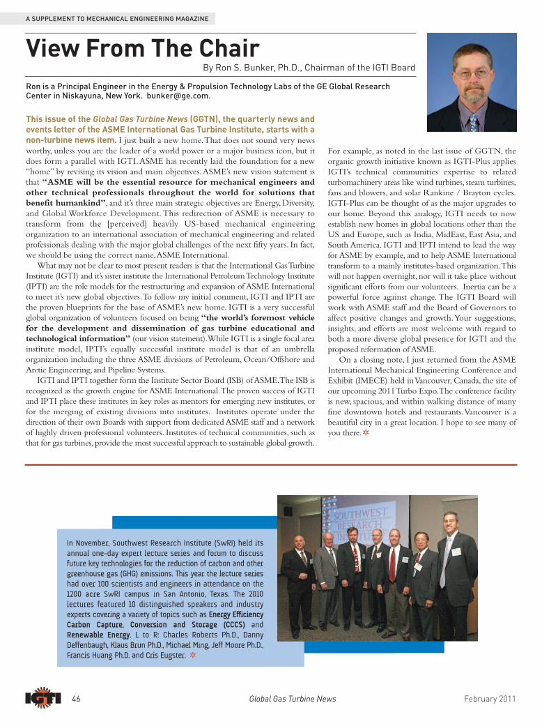
In November, Southwest Research Institute (SwRI) held itsannual one-day expert lecture series and forum to discussfuture key technologies for the reduction of carbon and othergreenhouse gas (GHG) emissions. This year the lecture serieshad over 100 scientists and engineers in attendance on the1200 acre SwRI campus in San Antonio, Texas. The 2010lectures featured 10 distinguished speakers and industryexperts covering a variety of topics such as Energy EfficiencyCarbon Capture, Conversion and Storage (CCCS) andRenewable Energy. L to R: Charles Roberts Ph.D., DannyDeffenbaugh, Klaus Brun Ph.D., Michael Ming, Jeff Moore Ph.D.,Francis Huang Ph.D. and Cris Eugster. R

February 2011 Global Gas Turbine News 47
A SUPPLEMENT TO MECHANICAL ENGINEERING MAGAZINE
ASME Turbo Expo 2011 Keynote Speakers . . . CONTINUED FROM PAGE 45
JUNE 6-10, 2011 ASME Turbo Expo 2011Vancouver Convention & Exhibition Centre | Vancouver, BC, CanadaIGTI’s flagship event comprises a major gas turbine conference and exhibition. Visit www.turboexpo.org for more details.
JUNE/JULY 2011Gas Turbine Courses at Cranfield University, Bedfordshire, UKhttp://www.cranfield.ac.uk/soe/shortcourses/gte/June 20-24: Combined Cycle Gas Turbines CourseJune 27 – July 1: Gas Turbine Combustion
AUGUST 1-3, 2011AIAA/ASME/SAE/ASEE Joint Propulsion Conference & Exhibit San Diego Convention Center | San Diego, CA The objective for JPC 2011 is to identify and highlight how innovative aerospace propulsiontechnologies powering both new and evolving systems are being designed, tested, and flown. Visit www.aiaa.org for more details
SEPTEMBER 12-15, 201140th Turbomachinery Symposium George R. Brown Convention Center | Houston, TXThe Symposium, which features technical sessions and an exposition, focuses on users concerned withmaintenance, performance, troubleshooting, operation, and purchase of rotating equipment
NOVEMBER 13-18, 2011International Gas Turbine Congress 2011 Osaka, JapanThe IGTC'11 promises to continue the tradition of nine previous congresses held in Japan, bringingtogether people from academia, industry, and government to share in the latest information ondevelopments in the field of gas turbines, turbochargers, steam turbines, and their applications. For more info, visit: http://www.gtsj.org/english/igtc/IGTC11/index.html
JUNE 11-15, 2012ASME Turbo Expo 2012Bella Center | Copenhagen, DenmarkIGTI’s flagship event comprises a major gas turbine conference and exhibition.
FEBRUARY 13-16, 20111st Middle East Turbomachinery Symposium (METS)Sheraton Resort and Convention Center | Doha, QatarOrganized by the Turbomachinery Laboratory at Texas A&M University and TexasA&M University at Qatar, METS will be closely modeled after theTurbomachinery Symposium that has been held in Texas since 1971. For more information visit: MiddleEastTurbo.tamu.edu
FEBRUARY 14-18, 2011Gas Turbine Appreciation CourseCranfield University | Bedfordshire, UKhttp://www.cranfield.ac.uk/soe/shortcourses/gte/page4510.html
FEBRUARY 21-25, 2011ASME International Gas Turbine Institute Training WeekSouthwest Research Institute | San Antonio, TX USAFebruary 21-22: Introduction to Gas Turbines and Centrifugal CompressorsFebruary 23: Root Cause Failure Analysis of Gas TurbinesFebruary 24: Compressor Performance Testing and DynamicsFebruary 25: Machinery Performance Testing & TroubleshootingFor more info and to register, visit http://igti.asme.org
MAY 2011Gas Turbine Courses at Cranfield University, Bedfordshire, UKhttp://www.cranfield.ac.uk/soe/shortcourses/gte/May 9-13: Mechanical Integrity of Gas TurbinesMay 16-20: Gas Turbine PerformanceMay 16-20: Gas Turbine Transient Performance:May 16-27: Gas Turbine Component Technology
JUNE 4-5, 2011 ASME Turbo Expo CoursesVancouver Convention & Exhibition Centre | Vancouver, BC, CanadaJune 4: Gas Turbine Operation & Maintenance
Technology & Applications of Turbine CoatingsJune 4 & 5: Advances in Turbines Aero-Thermo-Mechanical Design & Analysis
Gas Turbine Aerothermodynamics & Performance CalculationsJune 5: Basic Gas Turbine Metallurgy & Repair Technology
Introduction to Optimization Methods & Tools for Multi-Disciplinary Design in Turbomachinery
CALENDAR OF EVENTS
DON’T MISS THESE TURBO EXPO EVENTS:Technical Conference
Turbo Expo has a well-earned reputation for bringing together the best and brightestexperts from around the world to share the latest in gas turbine technology, research anddevelopment, and application. Now, the IGTI community is enhancing its leadership rolein turbomachinery as it broadens the program scope to include related topics from windand steam turbine technology as well as fans and blowers and the Solar Brayton andRankine Cycle. The 2011 Technical Conference proceedings, alone, are worth the price ofadmission, as the DVD will contain over 1,000 peer-reviewed publications! Exposition
Now in its 56th year, ASME Turbo Expo is recognized as the must attend event forturbomachinery professionals. Turbo Expo offers unrivalled networking opportunities with adedicated and diverse trade show floor. The 3-day exhibition attracts the industry’s leadingprofessionals and key decision makers, whose innovation and expertise are helping to shapethe future of the turbomahinery industry. Join ANSYS, CD-adapco, GE, Pratt & Whitney,Sulzer Metco, and many more on the floor! Daily lunches plus afternoon networking recep -tions in the exposition are included in the registration package for delegates and exhibitors. Career Development Courses
Taking place just before the conference begins, our Turbo Expo short courses providefocused, fundamental training. Choose from several courses to be held Saturday and Sunday,June 4-5, 2011. Register for the conference and then take advantage of the opportunity toattend short courses while you are in Vancouver! Course topics include gas turbineoperation and maintenance, metallurgy and repair, turbine coatings, aero-thermo-mechanical design, aerothermodynamics and performance calculations, and optimizationmethods & tools for multi-disciplinary design in turbomachinery. See page 50 for moredetails and visit www.turboexpo.org to register.
Annual Women’s DinnerWomen working in the turbomachinery industry who
register for Turbo Expo are eligible to attend our women’snetworking reception and dinner. The dinner will be heldduring Turbo Expo on Tuesday evening, June 7, 2011.Registered female delegates will receive an RSVP emailfrom IGTI later this spring. Be sure to respond promptly!This year the dinner is generously sponsored by both Pratt& Whitney and Siemens. Special Networking Event for Young Engineers
The ASME International Gas Turbine Institute (IGTI)provides invaluable professional development benefits forearly career engineers and students! Featuring the topexperts and leading companies in the field of turbo -machinery, there is no better place for young engineers tobe than Turbo Expo! While attending Turbo Expo 2011,young engineers won’t want to miss a special networkingevent on Wed., June 8, for rising engineers. This specialnetworking event will give young engineers the opportu -nity to meet a variety of representatives from the turbo -machinery industry as well as members of IGTI’s technicalcommittees. Come and meet potential mentors and seekadvice from industry experts during Turbo Expo inVancouver! Visit www.turbo.expo.org today for moredetails and to register. Students qualify for discountedregistration. R

A typical gas turbine (GT) ingests millions of pounds of airevery day. Therefore, even a small concentration of debris in theair can correlate to a large amount of debris in the GT. For example,10 ppm of debris in 400,000 lb/hr of air is equal to 4 lb/hr ofdebris. A GT inlet filtration system is used to protect the turbinefrom harmful debris which can lead to reduced efficiency andpower, component performance degradation, and blade failures. Inthis article, five steps are suggested for evaluating a current GT inletfiltration system and determining the need for any improvements.
STEP 1: THE OPERATING ENVIRONMENTThe first step to evaluate an inlet filtration system is to study the
operating environment. It is important to understand what must beremoved from the air by the filtration system before evaluating theexisting system. The environment, type of debris, and amount ofdebris dictates how the filtration system should be configured andmaintained. Operating environments can be classified into ninemain categories. These categories and a list of common debris aresummarized in Figure 1. A GT may operate in one or more ofthese environments throughout the year.
In addition, there can be local, seasonal, and/or temporary debrisin the air. Plant emissions are one example of a localized source. Thelayout of the plant site with respect to the turbine inlet willinfluence how much soot from exhaust, cooling tower aerosols, orother emissions enter the inlet filtration system. Other examples oflocalized sources are mining operations or agricultural sites. Seasonalchanges and weather patterns (wind, humidity, precipitation, andtemperature) will also affect what must be filtered. Lastly, temporarysources such as construction sites will affect air quality.
When defining the operating environment, the first step is tocomplete a visual survey of the operating site and surrounding area.Next, an air quality survey can be completed near the turbine toobtain information on debris size and concentration. It is also valu -able to complete compositional analyses on used filters and samplesof deposits from the first stages of the compressor. This will giveinsight into what is and is not being removed from the air with thecurrent system.
STEP 2: THE EXISTING SYSTEMOnce the operating environment is defined, the existing filtration system
can be evaluated. The configuration of the filtration system should alreadybe documented or it can be determined from visual inspection. Themajority of filtration systems in operation have multiple stages and eachstage should be defined. An example of documentation of a filterconfiguration is shown in Figure 2.
The operator can evaluate the system by comparing the debris in the airand the type of filtration system the GT has. A brief description of differentfilter components and their purposes is provided in Figure 3. During theevaluation, it is important to consider filtration efficiency, volumetric flowrate, and pressure loss. In addition, a visual inspection of the filtration systemshould be performed before filters are replaced. Some specific items thatshould be noted are: • Filters are wet or dry (wet filters are an indication that water is entering
the system),• Rust in filter housing (this indicates that water is entering system and
housing is degrading),• Loading of filters across entire filter bank (look for even loading and if
filters need replacement),• Leaks in the filtration system (leaks defeat the purpose of the filtration
system and should be sealed),• Installation of filter elements (ensure filters are being installed correctly),• Damaged filter elements (determine root cause of damage: FOD,
material defect, filter overloaded, or wet filter), and• Deposits on housing downstream of the last filter stage or deposits on
first stages of compressor (indication of what is not being removed byfiltration system).A review of these items will provide the operator with a comprehensive
assessment of the current state of the inlet filtration system.
STEP 3: MAINTENANCE PRACTICESMaintenance is an important part of any system. It ensures that the
system will stay in an operable condition and perform as required. There areseveral tasks which, if performed consistently and correctly, can ensure thatthe filtration system operates properly.
The largest maintenance item of a filtration system is the replacement ofthe filters. Filters are designed for a certain lifespan which is quantified by
48 Global Gas Turbine News February 2011
A SUPPLEMENT TO MECHANICAL ENGINEERING MAGAZINE
Five Steps to Evaluate a Gas Turbine Inlet AirFiltration System
By Melissa Wilcox, Research Engineer, Machinery Structural Dynamics Group, Mechanical Engineering Division of Southwest Research Institute, www.machinery.swri.org
Figure 1. Debris in Several Different Environments
Figure 2. Example of Filtration System Configuration

February 2011 Global Gas Turbine News 49
A SUPPLEMENT TO MECHANICAL ENGINEERING MAGAZINE
the pressure loss across the filter. This should be monitored in the filtrationsystem. Each filter is prescribed an initial and final pressure loss and amaximum lifespan by the manufacturer. The filters should be replaced whenthey either reach the final pressure loss or maximum calendar lifespan. Filtersoperating past this will have reduced filtration efficiency and high pressurelosses. Leaving fully loaded filters operating will lead to reducedperformance and increased degradation of the GT, and the possibility ofcomplete filter failure/collapse. This will result in bypass of the system andthus GT contamination.
In addition to filter replacements, maintenance needs to be performedon any auxiliary systems. This can include drainage systems, self-cleaningsystems, and/or anti-icing systems. Also, inspection should be performedperiodically including: filter condition, filter to frame seal leaks, seals onfilter housing joints, inspection ports and doors (closed and sealedproperly), drainage points, water drains for plugging, flexible connectionsin draining system.
If maintenance practices are found to be inadequate, a primary focusshould be placed on correcting filter replacement intervals and inspectingthe filtration system for any leaks. After these items are improved, aninspection plan should be implemented. This will help to ensure thefiltration system performs properly in the future.
STEP 4: UPGRADES TO THE SYSTEMDuring the evaluation, the operator may find deficiencies in the current
filtration system. If this is the case, then upgrades should be considered. Thesystem can be upgraded on several levels. A filtration system, housing and all,could be completely replaced, or just the filter elements could be upgraded.When considering an upgrade, several items should be evaluated. • What are the requirements for inlet air filtration?• What are the weaknesses of the existing system?• What debris is not being removed by the system that should be
removed? • Could the filtration system perform as needed by changing out the
filters more often or is a different modification required?• Does the system have sufficient weather protection (snow, ice, rain)?• What is the expected performance of the GT while using the existing
system? Is this performance acceptable for the future operation?
Figure 3. Description of Common Filtration System Components
The operator must determine the benefits of upgrading thefiltration system. These can be realized in several areas: increasedfiltration efficiency, reduced degradation, improved gas turbineperformance, or decrease in pressure loss across filters. Whenevaluating upgrades to the filtration system, several different upgradeconfigurations should be evaluated for their cost and benefit.
STEP 5: OVERALL COST OF SYSTEMOne of the most straightforward methods for comparing the cost
and benefit of different filtration system options is by completing aLife Cycle Cost (LCC) analysis. This analysis quantifies the cost andperformance of a system in monetary terms to obtain a lifetime costof the system. The lifetime costs between two different systemoptions can be directly compared.
An LCC analysis for a filtration system has seven maincomponents: initial costs, maintenance costs, availability andreliability considerations, GT degradation losses, compressorwashing effects, pressure loss effects, and potential failures or eventscosts. The initial cost is the main cost that is typically consideredwhen looking at upgrading a system. This cost is important for anLCC analysis, but not necessarily the most important or dominantcost. Costs associated with maintenance (i.e. replacement parts,labor, and downtime) and those associated with GT performance(i.e. efficiency) are also important components of an LCC. Theeffects of the inlet filtration system performance (pressure loss andGT performance degradation) are quantified by placing monetaryvalues on lost power, increases in heat rate, and reduced efficiency.
Once all of the costs of a filtration system are quantified, alifetime cost of the system in terms of present value is found. Sinceinlet filtration systems do not produce a profit, the system with theleast negative value will have the best lifetime cost. The advantageof an LCC analysis is that it provides a method to perform anobjective analysis of different filtration system upgrades.
By completing the five steps described above, the operator canevaluate the current filtration system. This includes determiningwhat debris must be removed from the air, verifying theconfiguration of the current system, identifying weaknesses in thefiltration system, evaluating the current maintenance practices,considering possible upgrades, and analyzing the cost and benefit ofchanges to the system. The results of these tasks will providedirection for improvements in the operation and performance ofthe inlet filtration system and GT. R

50 Global Gas Turbine News February 2011
A SUPPLEMENT TO MECHANICAL ENGINEERING MAGAZINE
Awards and Student ScholarshipsAvailable from IGTI:
New in 2011!IGTI will award 10 scholarships of $2,000 each, to students whosubmit all the required documentation and meet the qualifications.Applications will be accepted from February 15, 2011through April 15, 2011.Applications will be reviewed in June/Julyand the award winners will be notified in September and receivetheir scholarship in October. For application and requirements, pleasevisit the following web page: http://igti.asme.org/Honors/
Young Engineer Travel AwardIGTI offers several travel awards to students and young engineers
employed in industry or government to attend ASME Turbo Expo topresent papers of which they are authors. Please visit the IGTI web siteat http://igti.asme.org/ for more detailed information.
The International Gas Turbine Institute (IGTI)Scholarship Award
The ASME International Gas Turbine Institute awards one $4,000scholarship every year based on superior academic performance anddemonstrated interest in the gas turbine, propulsion, orturbomachinery industries to an undergraduate or graduate student.Applicants must be ASME Student Members in good standing at thetime of application. Applications are accepted online each year only from
January 15 through March 1. Application forms and detailedinstructions may be found at: http://www.asme.org/Education/College/FinancialAid/Details_Requirements.cfm R
Professional Development:n IGTI continues its successful partnership with Southwest Research
Institute to offer four hands-on training workshops. The “Training Week”will be held February 21-25, 2011 at the SwRI facility in San Antonio.
n IGTI will also continue its successful partnership with the von KarmanInstitute (VKI) to offer two NEW workshops: “Advances in TurbinesAero-thermo-mechanical Design and Analysis” and “Introduction toOptimization Methods and Tools for Multi-disciplinary Design” inconjunction with Turbo Expo 2011 in Vancouver.
n Turbo Expo 2011 in Vancouver will also be the venue for four otherworkshops. “Gas Turbine Operation and Maintenance” and “Technologyand Applications of Turbine Coatings” are both new this year. Back bypopular demand, IGTI will offer “Gas Turbine Aerothermodynamics &Performance Calculations” and “Basic Gas Turbine Metallurgy andRepair Technology”.
If you have a topic you think will be of value to the turbineindustry and would like to present it in a webinar format or a “face-to-face” format, please contact Shirley at [email protected].
For detailed information on upcoming training events and webinarsfor the gas turbine industry, please visit the IGTI web site athttp://igti.asme.org/
Member Development:Please contact Shirley Barton regarding information on:
n Navigating the IGTI “Who’s Who” directoryn Committee member updatesn Volunteer opportunitiesn IGTI Awards and Scholarships
ASME IGTI Professional & Member Development
By Shirley Barton, IGTI Professional & Member Development Manager
The ASME Gas Turbine Award Award is given in recognition of an outstanding contribution to the literature ofcombustion gas turbines or gas turbines thermally combined with nuclear orsteam power plants.
R. Tom Sawyer Award Award is bestowed on an individual who has made contributions to advance thepurpose of the Gas Turbine Industry and to the International Gas TurbineInstitute over a substantial period of time.
The IGTI Industrial Gas Turbine Technology AwardFor sustained personal creative scientific or technological contributions uniqueto electric power or mechanical drive industrial gas turbine technology. Eligibleareas of accomplishment are gas turbine design, application, operations/maintenance, and research/development/deployment, performed in an industrial,academic or research laboratory environment.
The IGTI Aircraft Engine Technology Award For sustained personal creative contributions to aircraft engine technology inthe areas of aircraft engine design and/or research and development performedin an industrial, academic or research laboratory environment.
The IGTI John P. Davis Award Awarded annually by IGTI in recognition of the technical paper that mostsignificantly: describes new or continuing gas turbine applications; identifies planning, installation, operating and/or maintenance problems andtheir solutions; and exemplifies candid exposure of real-world problems andsolutions and is judged, therefore, to be of exceptional value to others supplyingor using gas turbines and their support systems. The Award was established in1985 and includes a US$1,000 honorarium (divided equally among recipients ifawarded to a multiple-author paper).
The IGTI Scholar Award Established in 1989, IGTI gives this Award biannually to a person with asignificant depth of knowledge in some aspect of gas turbine technology, whowrites and presents a learned and comprehensive paper to industry peers. Therecipient may be from industry, government, education, or private professionalpractice and need not be an ASME member.
IGTI Technical Committee Best Paper AwardsEach year the Technical Committees have the opportunity to select a paperpublished at ASME TURBO EXPO to receive their committee's Best Paper Award.This is a chance to recognize outstanding technical papers, to acknowledge theauthor's contributions to the gas turbine industry, and to support and maintainthe high quality of papers presented by each committee. Award recipients arehonored during individual committee meetings at ASME TURBO EXPO.
IGT I AWARDS. . .

References1. “The Anatomy of the Airbus A380 QF32 near disaster.” Sandilands, Ben, <blogs.crikey.com.au>,Nov. 17, 2010 – 7:56 PM.
2. “Disc failure almost brought superjumbo down.”, Creedy, Steve, <theaustralian.com.au/…/disc-failure-almost-brought-superjumbo…/>, Nov. 6, 2010 – 12:00 AM.
3. Engineering Progress Through Trouble,Whyte, R.R. ed., The Institution of Mechanical Engineers,1975.
4. National Transportation Safety Board, Safety Recommendation, to FAAAdministrator James B. Busey from Chairman James L. Kolstad,Dec. 14, 1990, A-90-167 through 175.
5. “Convergent Zone-Refinement Method for Risk Assessmentof Gas Turbine Disks Subject to Low-FrequencyMetallurgical Defects”, Millwater, H.R., Enright, M.P.and Fitch, S.H.K., ASME Journal of Engineering for GasTurbines and Power, July 2007, 129, pp. 827-835.
One historic example of progress through trouble occurred over twenty years agowith the inflight failure of a General Electric CF-6 fan disc and is graphicallydescribed in a 1990 U.S. National Transportation Safety Board document[4]:
“On July 19, 1989, at 1516, a DC-10-10, N1819U, operated by UnitedAirlines (UAL) as flight 232, experienced a catastrophic failure of the No. 2tail-mounted engine during cruise flight. The separation, fragmentation andforceful discharge of stage 1 fan rotor assembly parts from the No. 2 engine ledto the loss of the three hydraulic systems that powered the airplane’s flightcontrols. The flightcrew experienced severe difficulties controlling the airplane,which subsequently crashed during an attempted landing at Sioux GatewayAirport, Iowa. There were 285 passengers and 11 crewmembers onboard. Oneflight attendant and 110 passengers were fatally injured.
The National Transportation Safety Board determines that the probable causeof this accident was the inadequate consideration given to human factorslimitations in the inspection and quality control procedures used by UnitedAirlines’ engine overhaul facility which resulted in the failure to detect afatigue crack originating from a previously undetected metallurgical defectlocated in a critical area of the stage 1 fan disk that was manufactured byGeneral Electric Aircraft engines. The subsequent catastrophic disintegration ofthe disk resulted in the liberation of debris in a pattern of distribution and withenergy levels that exceeded the level of protection provided by design features ofthe hydraulic systems that operate the DC-10’s flight controls.”
As a result of the tragic 1989 Sioux City accident, the gas turbine industry,airlines and regulatory agencies have worked diligently over the intervening years toimprove disc inspection, crack detection, manufacturing techniques and fracturemechanics models. An example of the Sioux City work still ongoing is given in arecent ASME paper by Millwater, Enright and Fitch[5].
The troubles we have outlined here, have or will lead to gas turbine progress,which might be best summed by a quote used by Whyte[3]:
“Progress is the art of getting out of trouble you wouldn’t have been in if it was not for progress.”
A SUPPLEMENT TO MECHANICAL ENGINEERING MAGAZINE
February 2011 Global Gas Turbine News 51
An uncontained engine failure is a jet enginecompany’s worst nightmare. It usually involves thefailure and disintegration of a rotating disc associated with thefan, compressor or turbine of the gas turbine. Rotating atmany thousands of rpm, a disc holds and constrains metal orcomposite engine blades, each of which can be subjected tocentrifugal forces equivalent to 20,000 gs, or more. Thusarmed with enormous rotational kinetic energy, thedisintegrated parts of a failed disk and its blading will becomedangerous flying projectiles.
Such was the case of the inflight failure of the Rolls-Royce Trent 900 engine on Qantas Flight QF32 on themorning of November 4, 2010, with 466 passengers andcrew onboard. The super jumbo four engine Airbus A380had just taken off from Changi International Airport,Singapore, bound for Sydney.
About 6 minutes after takeoff at 7,500 feet altitude overthe Indonesian island of Batam, the Trent 900 intermediatepressure turbine disc on engine No. 2 failed, sending engineparts shrapnel through the engine nacelle and the left wing.Passengers saw several perforations take place on the uppersurface of the wing above engine No. 2, resulting in one holeas large as 65 by 80 cm[1]. Now powered by three of the fourengines, the A380 circled to dump fuel (which was alsoleaking out of two wing tanks, above the failed engine). TheQantas plane then returned to Changi Airport, to landwithout thrust reversers, using emergency pressurizednitrogen to lower landing gear since the hydraulic systemhad been compromised by the uncontained engine failure.Controls to engine No. 1 had been damaged, so that thepilots were unable to shut it down after landing. Airportfirefighters flooded No. 1 engine with foam to shut it down,further increasing the overall damage cost[2].
Fortunately, all Flight QF32 passengers and crew weresafe and uninjured, after this uncontained engine failure. As Iwrite this, Rolls-Royce and European regulators havetentatively identified the intermediate pressure turbine discfailure to be caused by an interior oil fire, highlighting an oilleak from oil service tubes for shaft bearing lubrication.Speculation by others include the possibility of a bearingfailure, causing the intermediate shaft to break, resulting insudden overspeed of the turbine disc. More will be knownafter the Australian Transport Safety Bureau issues apreliminary report.
If engine history holds true, this very serious uncontainedengine failure can result in valuable engineering progress, asthe reasons for the failure become known. In theintroduction of Engineering Progress Through Trouble[3], SirHenry Guy is quoted, who avowed in 1942 that:
“One begins to recognize that falling intotrouble, encountering some unexpected
difficulty however harassing at the time, is infact an opportunity for making a fresh advanceand most advances in engineering have in factbeen made by turning failure into success.”
Featured Column: As the Turbine Turns...
Gas Turbine Progress through TroubleBy Dr. Lee S. Langston, Professor Emeritus of Mechanical Engineering, University of Connecticut
Recovered R-R Trent 900 intermediate pressure turbinedisc segment from Qantas A380 Flight QF32. Photoprovided by Australian Air Transport Safety Bureau,courtesy of Aviation Week & Space Technology.

Producing the turbine pin wheel in gold /rhodium necessitated the creation of a turbinepin wheel mould. In the end a multi-pointinlet mould was developed, as in Figure B.
Two turbine pin wheels were produced inthe preferred alloy, and then the other cuff linkcomponents manufactured in the same alloy.Sheard found the finished cuff links (in FigureC) to be quite difficult to photograph, as thehigh polish reflected the light and madefocusing difficult.
“I use the cuff links regularly now, but didhave to go out and buy a new set of shirts thatcould actually accommodate cuff links, muchto the irritation of my long-suffering wife. Bitof an oversight really, spending five yearsdeveloping a set of cuff links and only thenrealizing that I did not have any shirts thatcould use cuff links! Nevertheless, it was aneasily-rectified problem when put into thecontext of those problems already overcome,”said Sheard.
Upon completion of the project Sheard investigated whether the cuff links would beaffordable to purchase on a commercial basis, since he thought there might be someinterest among other IGTI volunteers.
“Rather regrettably, the very high cost of gold and rhodium today means that thisdesign would retail at $1,500, so it is not really an option. I then inquired aboutproducing the design in silver; however, the labor involved is still significant, particularlyregarding the turbine pin wheel, meaning that the design in silver is still about $375. Assuch, pure economic considerations mean that my pair of cuff links is likely to remainunique,” said Sheard.
Despite producing his now-wearable jewelry, Sheard is still laboringover his cuff link project. He is now in the process of having an oak cufflink box constructed – from materials of the British Naval flagship,HMS Victory, which has been undergoing restoration. R
52 Global Gas Turbine News February 2011
A SUPPLEMENT TO MECHANICAL ENGINEERING MAGAZINE
Most former IGTI Technical Committee Chairs arefamiliar with the turbine wheel jewelry that hasserved as tokens of appreciation for their service.The turbine wheels were originally designed to fitaround the ASME member pin, which could easily befastened on a lapel and worn with pride. However, overthe years, ASME has changed the shape of the member -ship pins and the current ones no longer fit the existingwheels – leaving some members unable to wear theirturbine wheels if their old member pins got misplaced.
Geoff Sheard, a former technical committee chair andcurrent chair of IGTI’s Controls, Diagnostics &Instrumentation Committee, devised a creative way toonce again wear his turbine wheels: he turned them intocuff links!
“When I set myself this goal I had absolutely no ideahow difficult it would be to achieve; however, anobsessive and compulsive personality disorder is good forone thing - you don't quit just because the going getstough,” said Sheard.
After four years searching for a jeweler willing to takeon the commission, he found one with an innovativeapproach to jewelry design. Six months later Sheardproduced the design in Figure A.
“A critical design featurewas that the turbine pin wheelshould spin on the cuff link.This made the design rathermore challenging; however, mydesign was essentially adoptedwith one proviso - the materialshad to be the same material for all components, asotherwise the bearing surface between the turbine pinwheel and the cuff link body would be prone tocorrosion. The jeweler preferred the mechanicalproperties of 18 carat gold alloyed with rhodium forultimate mechanical strength. This combination of agold/rhodium alloy has only one practical problem - it isthe most expensive of gold alloys,” said Sheard.
IGTI Volunteer Shows InnovationBeyond His Work
Figure C Finished Cuff Links
Figure B Multi-point Inlet Mould
Figure A Cuff Link DesignComponents
Geoff Sheard is Vice President -Fan Technology and Director-
Tunnel & Metro for Fläkt Woods,www.fläktwoods.com