Embed Size (px)
Citation preview
Registers
CPE 49RMUTIKOTAT

Shift Registers• Capability to shift bits
♦ In one or both directions
• Why?♦ Part of standard CPU
instruction set♦ Cheap multiplication♦ Serial communications
• Just a chain of flip-flops
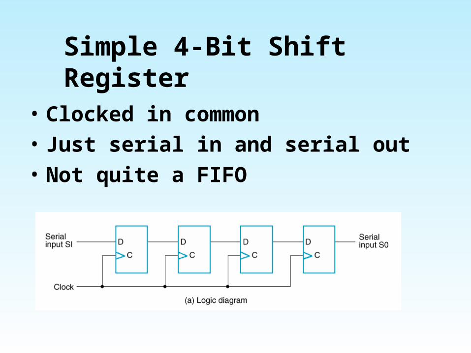
Simple 4-Bit Shift Register
• Clocked in common• Just serial in and serial out• Not quite a FIFO
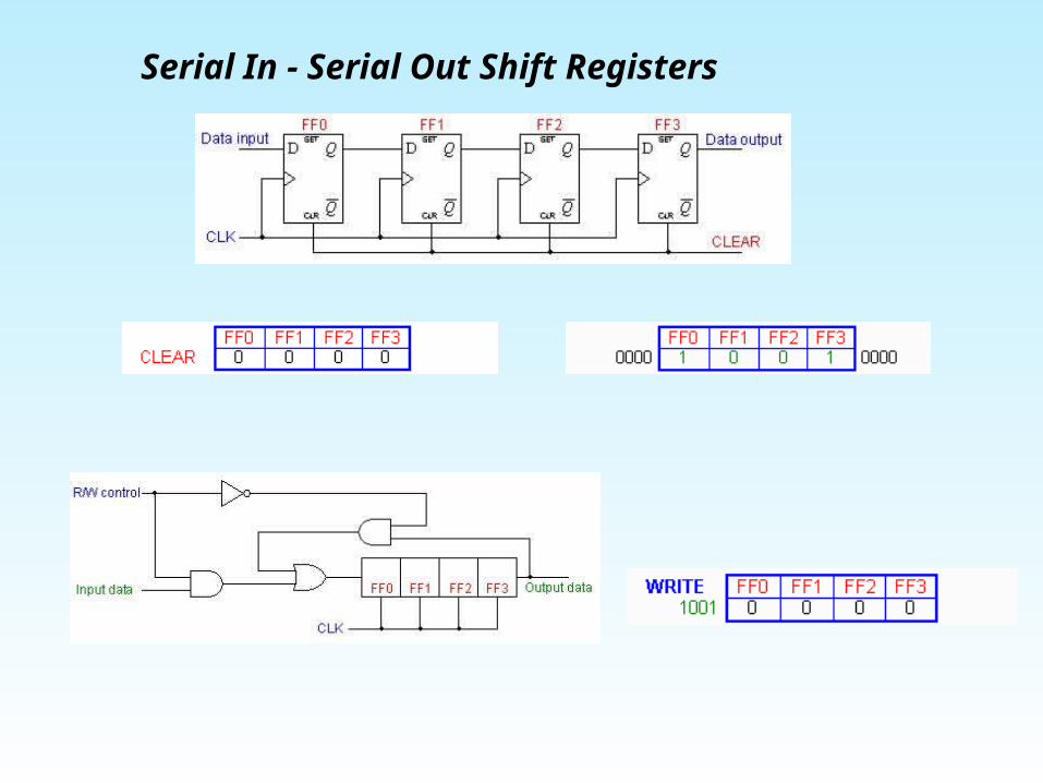
- Serial In Serial Out Shift Registers
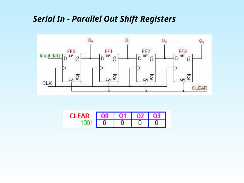
- Serial In Parallel Out Shift Registers
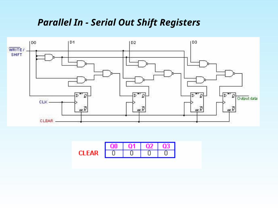
- Parallel In Serial Out Shift Registers
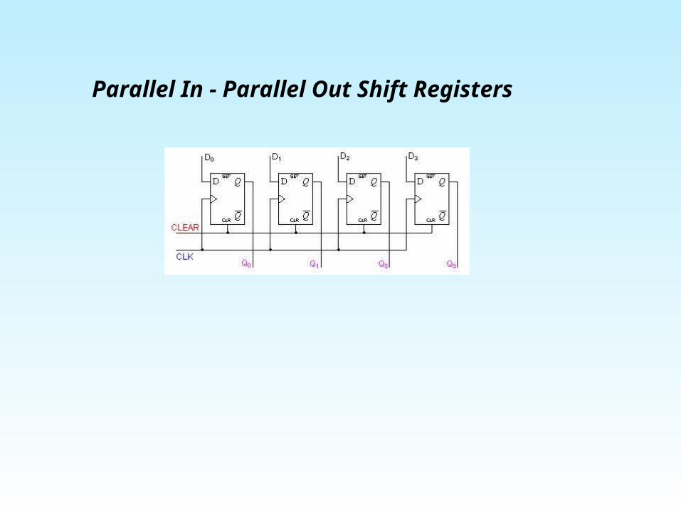
- Parallel In Parallel Out Shift Registers
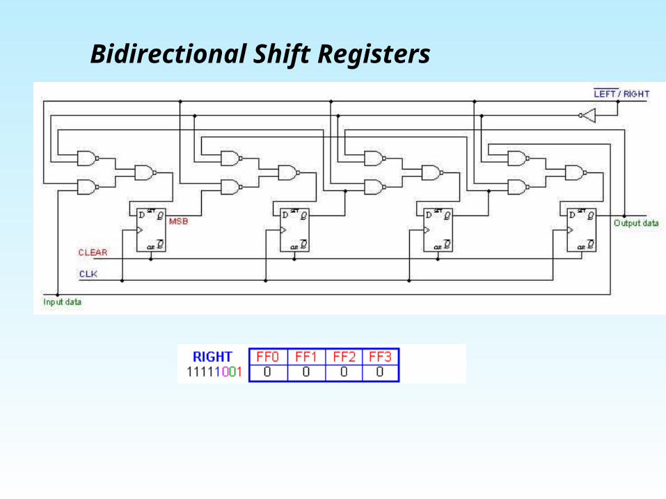
Bidirectional Shift Registers
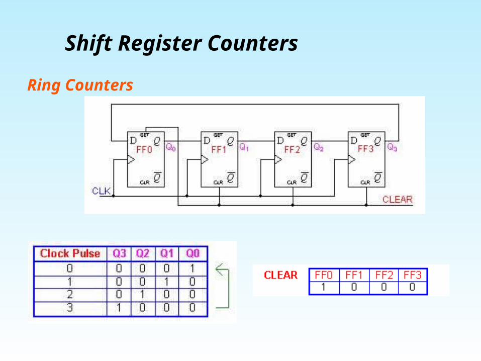
Shift Register Counters
Ring Counters
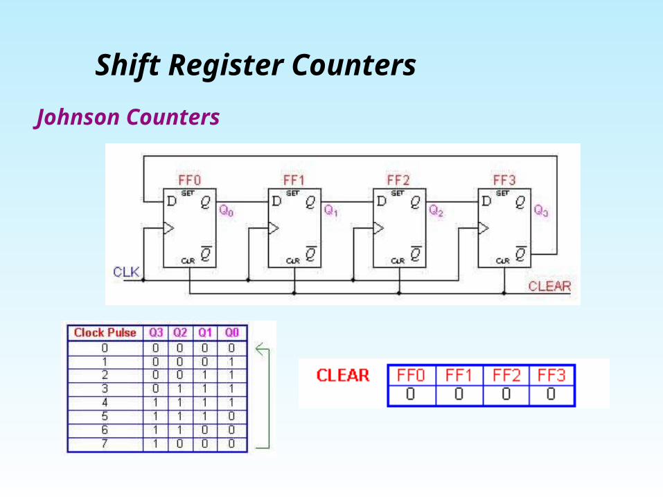
Shift Register Counters Johnson Counters
Applications To produce time delay
The serial in -serial out shift register can be used as a time delay device. The amount of delay can be controlled by: - the number of stages in the register - the clock frequency
To simplify combinational logic
The ring counter technique can be effectively utilized to implement synchronous sequential circuits. A major problem in the realization of sequential circuits is the assignment of binary codes to the internal states of the circuit in order to reduce the complexity of circuits required. By assigning one flip-flop to one internal state, it is possible to simplify the combinational logic required to realize the complete sequential circuit. When the circuit is in a particular state, the flip-flop corresponding to that state is set to HIGH and all other flip-flops remain LOW.
Applications
To convert serial data to parallel data
A computer or microprocessor-based system commonly requires incoming data to be in parallel format. But frequently, these systems must communicate with external devices that send or receive serial data. So, serial-to-parallel conversion is required. As shown in the previous sections, a serial in - parallel out register can achieve this.
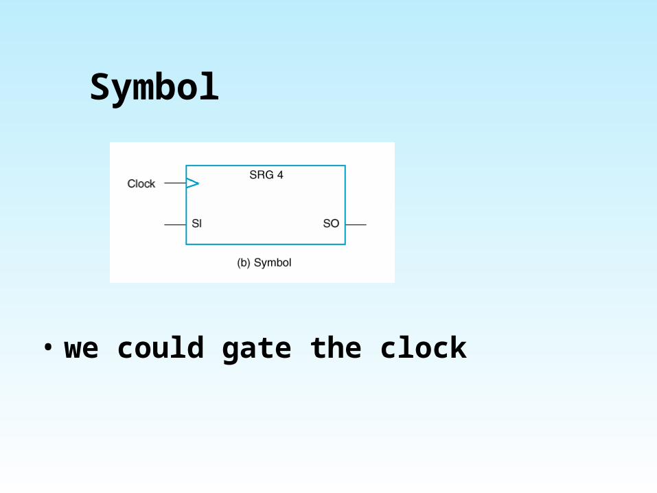
Symbol
• we could gate the clock

Parallel Load
• Can provide parallel outputs from flip-flops
• And also parallel inputs
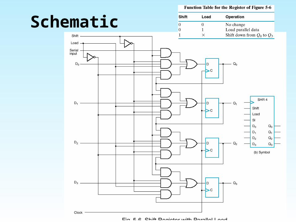
Schematic

Why is this useful?
• Basis for serial communications• Keyboard• Serial port
♦ Initially to connect to terminals♦ Now mainly for modem
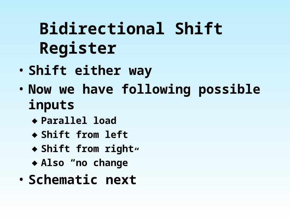
Bidirectional Shift Register
• Shift either way• Now we have following possible
inputs♦ Parallel load♦ Shift from left♦ Shift from right♦ Also “no change”
• Schematic next
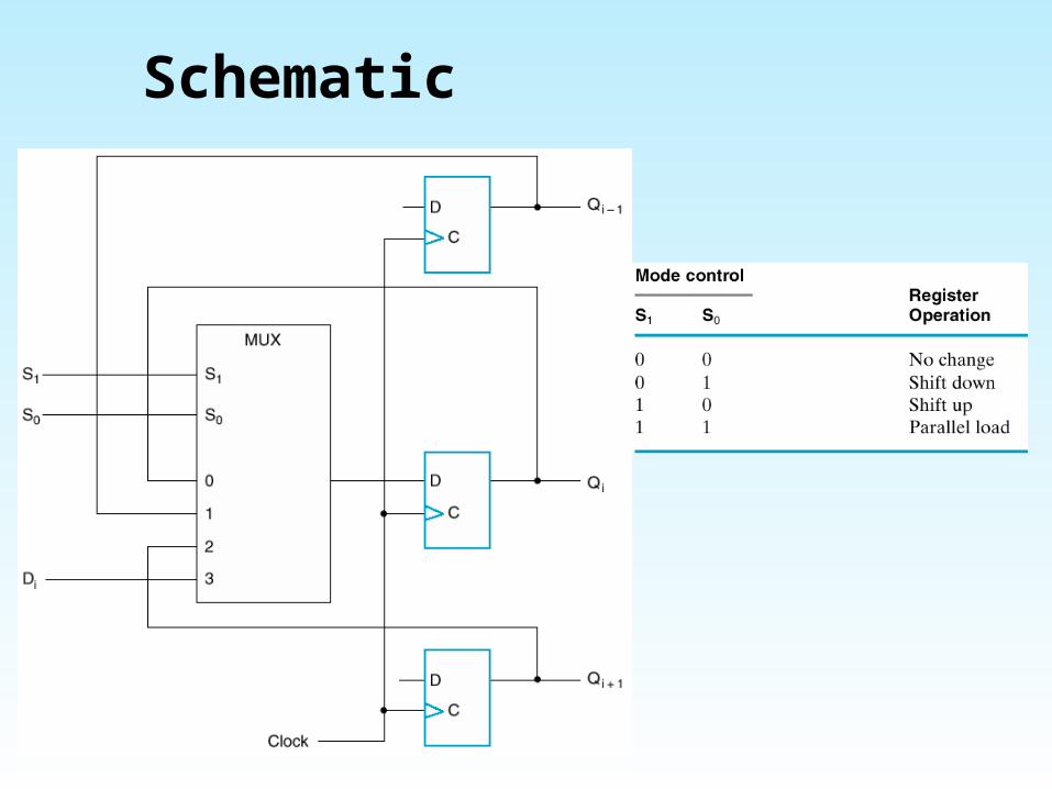
Schematic
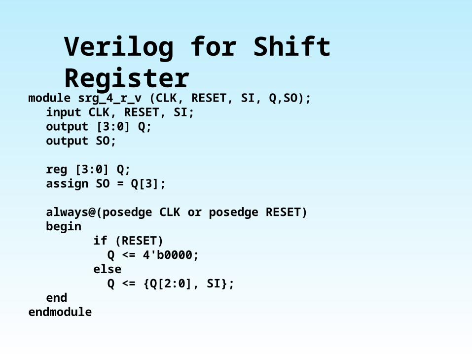
Verilog for Shift Registermodule srg_4_r_v (CLK, RESET, SI, Q,SO);
input CLK, RESET, SI;output [3:0] Q;output SO;
reg [3:0] Q;assign SO = Q[3];
always@(posedge CLK or posedge RESET)begin
if (RESET) Q <= 4'b0000;else Q <= {Q[2:0], SI};
endendmodule
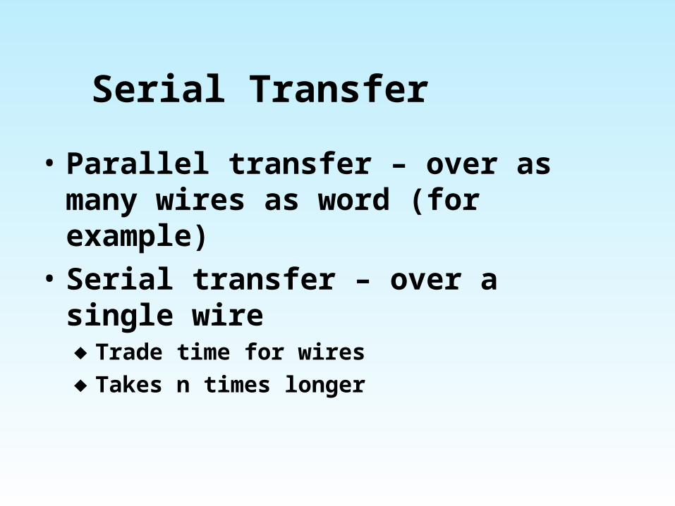
Serial Transfer
• Parallel transfer – over as many wires as word (for example)
• Serial transfer – over a single wire♦ Trade time for wires♦ Takes n times longer
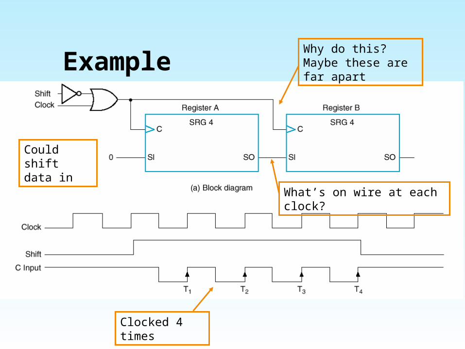
Example
Clocked 4 times
Why do this? Maybe these are far apart
Could shift data in
What’s on wire at each clock?
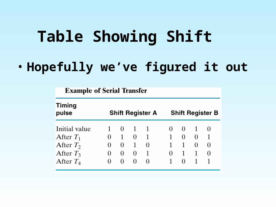
Table Showing Shift
• Hopefully we’ve figured it out
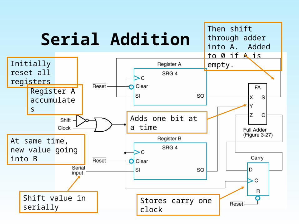
Serial Addition
Shift value in serially
Then shift through adder into A. Added to 0 if A is empty.
At same time, new value going into B
Adds one bit at a time
Stores carry one clock
Initially reset all registers
Register A accumulates
Hardware Comparison
• Serial vs. parallel adder• One full adder vs. n adders• Serial takes n units of time,
parallel only one
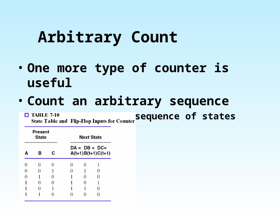
Arbitrary Count
• One more type of counter is useful
• Count an arbitrary sequence♦ Maybe you need a sequence of states
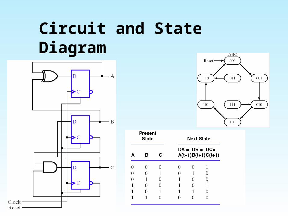
Circuit and State Diagram
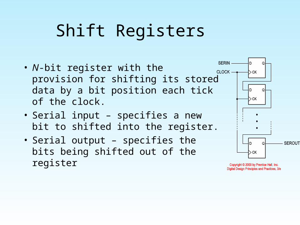
Shift Registers
• N-bit register with the provision for shifting its stored data by a bit position each tick of the clock.
• Serial input – specifies a new bit to shifted into the register.
• Serial output – specifies the bits being shifted out of the register
References
• http://www.eelab.usyd.edu.au/
digital_tutorial/part2/hpage.html
• http://www.allaboutcircuits.com/vol_4/index.html