Embed Size (px)
Citation preview
Regulation No. 51 協定規則第 51 号
Uniform provisions concerning the approval of motor vehicles having at least
four wheels with regard to their sound emissions
4 輪以上の自動車の音の発生に関する認可にかかわる統一規定
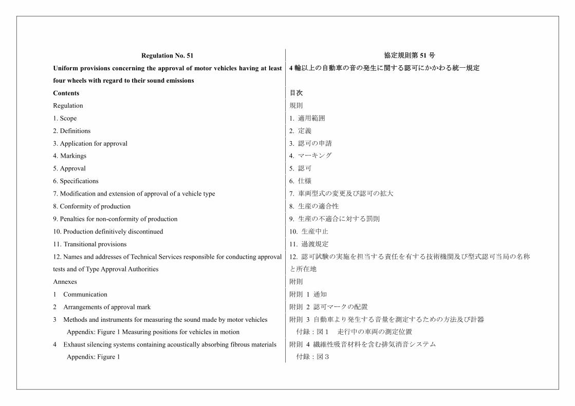
Contents 目次
Regulation 規則
1. Scope 1. 適用範囲
2. Definitions 2. 定義
3. Application for approval
4. Markings
3. 認可の申請
4. マーキング
5. Approval 5. 認可
6. Specifications 6. 仕様
7. Modification and extension of approval of a vehicle type 7. 車両型式の変更及び認可の拡大
8. Conformity of production 8. 生産の適合性
9. Penalties for non-conformity of production 9. 生産の不適合に対する罰則
10. Production definitively discontinued 10. 生産中止
11. Transitional provisions 11. 過渡規定
12. Names and addresses of Technical Services responsible for conducting approval
tests and of Type Approval Authorities
12. 認可試験の実施を担当する責任を有する技術機関及び型式認可当局の名称
と所在地
Annexes 附則
1 Communication 附則 1 通知
2 Arrangements of approval mark 附則 2 認可マークの配置
3 Methods and instruments for measuring the sound made by motor vehicles
Appendix: Figure 1 Measuring positions for vehicles in motion
附則 3 自動車より発生する音量を測定するための方法及び計器
付録:図1 走行中の車両の測定位置
4 Exhaust silencing systems containing acoustically absorbing fibrous materials
Appendix: Figure 1
附則 4 繊維性吸音材料を含む排気消音システム
付録:図3
5 Compressed air noise
Appendix: Figure 1
附則 5 圧縮空気の騒音
付録:図1
6 Checks on conformity of production 附則 6 生産の適合性の検査
7 Measuring method to evaluate compliance with the Additional Sound Emission
Provisions
Appendix 1: Statement of Compliance with Additional Sound Emission
Provisions
附則 7 音の発生に関する追加規定への適合を評価するための測定方法
付録:音の発生に関する追加規定の適合書
1. Scope 1. 適用範囲
This Regulation contains provisions on the sound emitted by motor vehicles and
applies to vehicles of categories M and N 1.
The specifications in this Regulation are intended to reproduce the sound levels
which are generated by vehicles during normal driving in urban traffic.
本規則は、自動車から排出される音の規定であって、カテゴリーM及びN*1の
自動車に適用する。
本規則は、市街地交通における通常運転中の自動車により発生する音圧レベル
を再現することを目的とする。 1 As defined in the Consolidated Resolution on the Construction of Vehicles (R.E.3.),
document ECE/TRANS/WP.29/78/Rev.3, para. 2 -
www.unece.org/trans/main/wp29/wp29wgs/wp29gen/wp29resolutions.html
*1 車両構造統合決議(R.E.3)、文書 ECE/TRANS/WP.29/78/Rev.3、2.
(www.unece.org/trans/main/wp29/wp29wgs/wp29gen/wp29resolutions.html)に記載の通
り。
2. Definitions 2. 定義
For the purposes of this Regulation, 本規則の意図するところでは、
2.1. “Approval of a vehicle” means the approval of a vehicle type with regard to
sound;
2.1. 「車両の認可」とは、音にかかわる車両型式の認可をいう。
2.2. “Vehicle type” means a category of motor vehicles which do not differ in such
essential respects as:
2.2. 「車両型式」とは、下記の本質的な観点において相違のない車両の区分を
いう。
2.2.1. For vehicles tested according to Annex 3, paragraph 3.1.2.1.: 2.2.1. 附則3の3.1.2.1.に従って試験される車両。
2.2.1.1. The shape or materials of the engine compartment and its soundproofing; 2.2.1.1. 原動機室内及びその防音装置における形状又は材料。
2.2.1.2. The type of engine (positive or compression ignition, two- or four-stroke,
reciprocating or rotary piston), number and capacity of cylinders, number and type
of carburetors or injection system, arrangement of valves, or the type of electric
2.2.1.2. 原動機の型式(強制点火又は圧縮点火、2ストローク又は4ストロー
ク、レシプロ又はロータリー)、シリンダー数と容量、キャブレターの数と種
類、噴射システムの種類、バルブの配置、又は電動機の型式。
motor;
2.2.1.3. Rated maximum net power and corresponding rated engine speed(s);
however if the rated maximum net power and the corresponding rated engine speed
differs only due to different engine mappings, these vehicles may be regarded as
from the same type;
2.2.1.3. 最高出力及びそのエンジン回転数。ただし、最高出力及びそのエンジ
ン回転数が、エンジンマッピングのみを原因として異なる場合、これらの車両
は同一型式とみなすことができる。
2.2.1.4. The silencing system. 2.2.1.4. 消音システム
2.2.2. For vehicles tested according to Annex 3, paragraph 3.1.2.2.: 2.2.2. 附則3の3.1.2.2.に従って試験された車両。
2.2.2.1. The shape or materials of the engine compartment and its soundproofing; 2.2.2.1. 原動機室内及びその防音装置における形状又は材料。
2.2.2.2. The type of engine (positive or compression ignition, two- or four-stroke,
reciprocating or rotary piston), number and capacity of cylinders, type of injection
system, arrangement of valves, rated engine speed (S), or the type of electric
motor;
2.2.2.2. 原動機の型式(強制点火又は圧縮点火、2ストローク又は4ストロー
ク、レシプロ又はロータリー)、シリンダー数と容量、噴射システムの種類、
バルブの配置、最高出力時のエンジン回転数、又は電動機の型式。
2.2.2.3. Vehicles having the same type of engine and/or different overall gear ratios
may be regarded as vehicles of the same type;
2.2.2.3. 同一型式の原動機において異なる総変速比(タイヤ径を含む)を有す
る車両は、同一型式の車両とみなすことができる。
2.3. However, if the differences in 2.2.2. provide for different target conditions, as
described in 3.1.2.2. of Annex 3, these differences are to be considered as a change
of type;
2.3. ただし、2.2.2.における相違が、附則3の3.1.2.2.に規定する目標条件が異な
る場合には別型式とする。
2.4. “Mass of a vehicle in running order” (mro) means 2.4. 「ランニングオーダー車両質量」(mro)とは
(a) In the case of a motor vehicle:
The mass of the vehicle, with its fuel tank(s) filled to at least 90 per cent of its or
their capacity/ies, including the mass of the driver, of the fuel and liquids, fitted
with the standard equipment in accordance with the manufacturer’s specifications
and, when they are fitted, the mass of the bodywork, the cabin, the coupling and
the spare wheel(s) as well as the tools;
(a) 自動車の場合:
燃料タンクがその容量の最低90%まで満たされており、運転者、燃料及び液体
の質量を含み、自動車製作者の仕様に従って標準装備されている装置並びに装
着されている場合は車体、キャビン、カップリング、スペアホイール及び工具
を含んだ車両質量とする。
(b) In the case of a trailer:
The mass of the vehicle including the fuel and liquids, fitted with the standard
(b) トレーラーの場合:
燃料及び液体を含め、自動車製作者の仕様に従って標準装備されている装置並
equipment in accordance with the manufacturer’s specifications, and, when they
are fitted, the mass of the bodywork, additional coupling(s), the spare wheel(s) and
the tools.
びに装着されている場合は車体、追加のカップリング、スペアホイール及び工
具を含んだ車両質量とする。
2.5. “Technically permissible maximum laden mass” (M) means the maximum
mass allocated to a vehicle on the basis of its construction features and its design
performances; the technically permissible laden mass of a trailer or of a semi-
trailer includes the static mass transferred to the towing vehicle when coupled;
2.5. 「技術的最大許容質量」(M)とは、車両の構造特性及び設計性能に基づ
いて車両に割り当てられる最大質量をいう。牽引自動車の技術的最大許容質量
には、被牽引自動車の第5輪荷重を含む。
2.6. “Vehicle length” means a dimension which is measured according to ISO
standard 612-1978, term No. 6.1. In addition to the provisions of that standard,
when measuring the vehicle structural length the following devices shall not be
taken into account:
2.6. 「車両の長さ」とはISO 612-1978の6.1に従って測定される寸法をいう。
ISO規格の規定に加え、車両の構造上の長さを測定する場合は、下記の装置は
含めないものとする。
(a) Wiper and washer devices; (a) 窓ふき器及び洗浄液噴射装置、
(b) Front or rear marker-plates; (b) 前部又は後部の標識プレート、
(c) Customs sealing devices and their protection; (c) 税関シール装置及びその保護、
(d) Devices for securing the tarpaulin and their protection; (d) 防水シートを固定するための装置及びその保護、
(e) Lighting equipment; (e) 灯火装置、
(f) Rear view mirrors; (f) 後写鏡、
(g) Rear space watching aids; (g) 後部空間監視装置、
(h) Air-intake pipes; (h) 吸気管、
(i) Length stops for demountable bodies; (i) 取り外し可能な車体用レングスストップ、
(j) Access steps; (j) 昇降ステップ、
(k) Ram rubbers; (k) 当たりゴム、
(l) Lifting platforms, access ramps and similar equipment in running order, not
exceeding 200 mm, provided that the loading capacity of the vehicle is not
increased;
(l) 標準装置の積載用昇降装置、積載用スロープ、それらと同等のものであっ
て、積載能力が増加せず装置の全長が200mmを超えない装置、
(m) Coupling devices for motor vehicles. (m) 自動車用連結装置。
2.7. “Vehicle width” means a dimension which is measured according to ISO
standard 612-1978, term No. 6.2. In addition to the provisions of that standard,
when measuring the vehicle structural width the following devices shall not be
taken into account:
2.7. 「車両の幅」とは、ISO 612-1978の 6.2.に従って測定される寸法をいう。
ISO規格の規定に加え、車両の構造上の幅を測定する場合は、下記の装置は含
めないものとする。
(a) Customs sealing devices and their protection; (a) 税関シール装置及びその保護、
(b) Devices for securing the tarpaulin and their protection; (b) 防水シートを固定するための装置及びその保護、
(c) Tyre failure tell-tale devices; (c) タイヤ故障テルテール装置、
(d) Protruding flexible parts of a spray-suppression system; (d) はね上げ防止システムの突出している可撓性のある部品、
(e) Lighting equipment. (e) 灯火装置。
2.8. “Rated maximum net power” Pn means the engine power expressed in kW and
measured by the method pursuant to Regulation No. 85.
2.8. 「定格最大ネット出力」Pnとは、UN規則No. 85に準拠した方法で測定し、
kWで表記したエンジン出力をいう。
2.8.1“Total engine power” means the sum of all power from available propulsion
sources.
2.8.1. 「総エンジン出力」とは、利用可能な推進源からの全ての出力の合計を
いう。
2.9. “Rated engine speed, S” means the declared engine speed in min-1 (rpm) at
which the engine develops its rated maximum net power pursuant to Regulation
No. 85 or, where the rated maximum net power is reached at several engine speeds,
the highest one of those speeds.
2.9. 「定格エンジン回転数、S」とは、原動機が協定UN規則No. 85に準じて定
格最大ネット出力を発揮するエンジン回転数の申告値で、min-1(rpm)単位で
表記したもの、又は、複数のエンジン回転数において定格最大ネット出力に達
する場合の最大の回転数をいう。
2.10. “Power to mass ratio index (PMR)” means a numerical quantity (see annex 3,
paragraph 3.1.2.1.1.) with no dimension used for the calculation of acceleration.
2.10. 「パワーマスレシオ(PMR)」とは、加速度の計算に使われる無次元数
(附則3の3.1.2.1.1.参照)をいう。
2.11. “Reference point” means one of the following points: 2.11. 「基準点」とは、以下の点のいずれかをいう。
2.11.1. In the case of vehicles of categories M1, N1 and M2 < 3,500 kg technically
permissible maximum laden mass:
2.11.1. カテゴリーM1、N1及び技術的最大許容質量が3,500kg以下のM2の車両の
場合。
(a) For front engine vehicles: the front end of the vehicle; (a) フロントエンジン車両の場合:車両の最前端、
(b) For mid-engine vehicles: the centre of the vehicle; (b) ミッドエンジン車両の場合:車両の中央、
(c) For rear engine vehicles: the rear end of the vehicle. (c) リアエンジン車両の場合:車両の最後端。
2.11.2. In the case of vehicles of categoriesy M2 > 3,500 kg technical permissible 2.11.2. 技術的最大許容積載質量が3,500kgを超えるカテゴリーM2、並びにM3、
maximum laden mass, M3, N2, N3: N2、N3の車両の場合。
(a) For front-engine vehicles, the front end of the vehicle; - フロントエンジン車両の場合、車両の最前端、
(b) For all other vehicles, the border of the engine closest to the front of the
vehicle;
- 他のすべての車両の場合、車両前端に最も近い原動機の縁部。
2.12. “Engine” means the power source without detachable accessories.
Power source includes in this context all sources of motive power; for example,
electric or hydraulic power sources used alone or in combination with other power
sources.
2.12. 「原動機」とは、取り外しができる補機類のない出力源をいう。
ここでいう出力源には、例えば、単独又は他の出力源との組み合わせで使用さ
れる電気又は液圧出力源など、すべての動力源が含まれる。
2.13. “Target acceleration” means acceleration at a partial throttle condition in
urban traffic and is derived from statistical investigations.
2.13. 「目標加速度」とは、市街地交通において部分的にスロットルを開いた
状態での加速度であって、統計的な調査より得られたものをいう。
2.14. “Reference acceleration” means the required acceleration during the
acceleration test on the test track.
2.14. 「参照加速度」とは、試験走行路上の加速試験で要求される加速度をい
う。
2.15. “Gear ratio weighting factor k” means a dimensionless numerical quantity
used to combine the test results of two gear ratios for the acceleration test and the
constant speed test.
2.15. 「変速段重み付け係数k」とは、加速試験と定速試験のために2つの変速
比の試験結果を組み合わせるために使用する無次元数をいう。
2.16. “Partial power factor kp” means a numerical quantity with no dimension used
for the weighted combination of the test results of the acceleration test and the
constant speed test for vehicles.
2.16. 「部分加速係数kp」とは、車両の加速試験と定速試験の試験結果を加重
して合算するために使用する無次元数をいう。
2.17. “Pre-acceleration” means application of acceleration control device prior to
AA' for the purpose of achieving stable acceleration between AA' and BB' as
referred to in Figure 1 of Appendix 1 to Annex 3.
2.17. 「予備加速」とは、附則3付録1の図1内にあるように、AA'とBB'の間で安
定した加速度を得るためにAA'よりも前に加速装置を作動させることをいう。
2.18. “Locked gear ratios” means the control of transmission such that the
transmission gear cannot change during a test.
2.18. 「変速比の固定」とは、変速段が試験中に変化することのないように変
速機を制御することをいう。
2.19. “Silencing system” means a complete set of components necessary for
limiting the noise produced by an engine, its intake and its exhaust (the exhaust
manifold(s), the catalyst(s) and emission after-treatment device(s) are not
2.19. 「消音システム」とは、原動機及びその原動機の吸気及び排気によって
生じる騒音を制限するために必要な構成部品一式をいう。(排気マニホール
ド、触媒及び排気後処理装置は消音システムの一部とはみなされない。これら
considered part of the silencing system; these parts belong to the engine). の部品は原動機に属する)。
2.20. “Design family of exhaust silencing system or exhaust silencing system
components” means a group of silencing systems or components thereof in which
all of the following characteristics are the same:
2.20. 「排気消音システム又は排気消音システム構成部品の設計ファミリー」
とは、以下の特性がすべて同じ消音システム又はその構成部品をいう。
(a) The presence of net gas flow of the exhaust gases through the absorbing fibrous
material when in contact with that material;
(a)繊維性吸収材料を通過する排気の正味ガス流の存在。
(b) The type of the fibres; (b) 繊維の種類、
(c) Where applicable, binder material specifications; (c) 該当する場合、結合剤材料の仕様、
(d) Average fibre dimensions; (d) 繊維の平均寸法、
(e) Minimum bulk material packing density in kg/m3; (e) kg/m³単位での最小バルク材充填密度、
(f) Maximum contact surface between the gas flow and the absorbing material. (f) ガス流と吸収材料との最大接触面。
2.21. “Exhaust silencing system of different types” means silencing systems which
significantly differ in respect of at least one of the following:
2.21. 「異なる型式の排気消音システム」とは、以下の項目において少なくと
も1つが明らかに異なる消音システムをいう。
(a) Trade names or trademarks of their components; (a) システムの構成部品の商号又は商標、
(b) The characteristics of the materials constituting their components, except for
the coating of those components;
(b) システムの構成部品のコーティングを除く、構成部品の材料の特性、
(c) The shape or size of their components; (c) システムの構成部品の形状又は寸法、
(d) The operating principles of at least one of their components; (d) システムの少なくとも1つの構成部品の作動原理、
(e) The assembly of their components; (e) システムの構成部品の組み立て、
(f) The number of exhaust silencing systems or components. (f) 排気消音システム又は構成部品の数。
2.22. “Replacement silencing system” means any part of the silencing system or its
components intended for use on a vehicle, other than a part of the type fitted to this
vehicle when submitted for type-approval pursuant to this Regulation.
2.22. 「交換用消音システム」とは、本規則に準じて型式認可用に提出する場
合に車両に装着される部品以外で、その車両での使用を対象とした消音システ
ム又はその構成部品をいう。
2.23. “R-point” means R-point as defined in paragraph 2.4. of Annex 1 to the
Consolidated Resolution on the Construction of Vehicles(R.E.3.).
2.23. 「Rポイント」とは、統合決議(R.E.3)附則1の2.4.に定義されたRポイン
トをいう。
2.24. Table of Symbols 2.24. 記号表を以下のとおり追加する。
Symbol Unit Annex Paragraph Explanation
mro kg Annex3 2.2.1. mass in running order;
value to be reported and
used for calculations to a
precision of 10 kg
mt kg Annex3 2.2.1. test mass of the vehicle;
value to be reported and
used for calculations to a
precision of 10 kg
mtarget kg Annex3 2.2.1. target mass of the vehicle
mxload kg Annex3 2.2.1. extra loading
mfa load unladen kg Annex3 2.2.1. front axle load in unladen
condition
mra load unladen kg Annex3 2.2.1. rear axle load in unladen
condition
munladen kg Annex3 2.2.1. unladen vehicle mass
mac ra max kg Annex3 2.2.1. Technically permissible
maximum laden mass
allowed for the rear axle as
declared by the
manufacturer
md kg Annex3 2.2.1. mass of driver
mchassis M2M3 kg Annex3 2.2.1. mass of the incomplete
vehicle (M2 or M3)
mxload M2M3 kg Annex3 2.2.1. extra load to be added to
the incomplete vehicle (M2
記号 単位 附則 項 解説
mro kg 附則3 2.2.1. ランニングオーダー質量
(10kg単位)。
mt kg 附則3 2.2.1. 車両の試験時質量(10kg単
位)。値を報告すること。
mtarget kg 附則3 2.2.1. 目標車両質量
mxload kg 附則3 2.2.1. 追加荷重
mfa load unladen kg 附則3 2.2.1. 非積載状態の前軸荷重
mra load unladen kg 附則3 2.2.1. 非積載状態の後軸荷重
munladen kg 附則3 2.2.1. 非積載車両質量
mac ra max kg 附則3 2.2.1. 自動車製作者等が申告した
後軸に関する技術的最大許
容質量
md kg 附則3 2.2.1. 運転者の質量
mchassis M2M3 kg 附則3 2.2.1. 未完成車(M2又はM3)の質
量
mxload M2M3 kg 附則3 2.2.1. 自動車製作者等が指定する
車両のランニングオーダー
or M3) to reach the mass of
the vehicle in running
order as chosen by the
manufacturer
mfa load laden kg Annex3 2.2.7.2. front axle load in laden
condition
mra load laden kg Annex3 2.2.7.2. rear axle load in laden
condition
AA' — Annex3 3.1.1. line perpendicular to
vehicle travel which
indicates beginning of
zone in which to record
sound pressure level
during test
BB' — Annex3 3.1.1. line perpendicular to
vehicle travel which
indicates end of zone in
which to record sound
pressure level during test
CC' — Annex3 3.1.1. line of vehicle travel
through test surface
defined in ISO 10844
PP' — Annex3 3.1.1. line perpendicular to
vehicle travel which
indicates location of
microphones
質量に達するようにするた
めに未完成車(M2又はM3)
に加える追加荷重
mfa load laden kg 附則3 2.2.7.2. 積載状態の前軸荷重
mra load laden kg 附則3 2.2.7.2. 積載状態の後軸荷重
AA' — 附則3 3.1.1. 試験中に騒音の大きさを記
録する区間の開始位置を示
し、車両走行線に直交する
直線
BB' — 附則3 3.1.1. 試験中に騒音の大きさを記
録する区間の終了位置を示
し、車両走行線に直交する
直線
CC' — 附則3 3.1.1. ISO 10844に定義された試験
路面を通過する車両走行線
PP' — 附則3 3.1.1. マイクロホンの位置を示
し、車両走行線に直交する
直線
vtest km/h Annex3 3.1.2.1. vehicle test speed
PMR — Annex3 3.1.2.1.1. power-to-mass ratio index
to be used for calculations;
value to be reported and
used for calculations to the
first decimal place
Pn kW Annex3 3.1.2.1.1. rated total engine net
power
l m Annex3 3.1.2.1.2. reference length; value to
be reported and used for
calculations to a precision
of 0.01 m (1 cm)
lveh m Annex3 3.1.2.1.2. length of vehicle; value to
be reported and used for
calculations to a precision
of 0.01 m (1 cm)
vAA’ km/h Annex3 3.1.2.1.2. vehicle velocity when
reference point passes line
AA' (see 5.1. for definition
of reference point); value
to be reported and used for
calculations to the first
decimal place
vBB’ km/h Annex3 3.1.2.1.2. vehicle velocity when
reference point or rear of
vehicle passes line BB'
vtest km/h 附則3 3.1.2.1. 試験車速
PMR — 附則3 3.1.2.1.1. 計算に用いるパワーマスレ
シオ。小数第1位までと
し、値を報告し、計算に使
用すること。
Pn kW 附則3 3.1.2.1.1. 最高出力(ネット)(トー
タル)
l m 附則3 3.1.2.1.2. 基準長さ。0.01m(1cm)単
位で報告され、計算に使用
される値。
lveh m 附則3 3.1.2.1.2. 車両の長さ。0.01m(1cm)
単位で報告され、計算に使
用される値。
vAA’ km/h 附則3 3.1.2.1.2. 基準点がAA’を通過したと
きの車両速度(基準点の定
義については5.1.参照)。小
数第1位までとし、値を報
告し、計算に使用するこ
と。
vBB’ km/h 附則3 3.1.2.1.2. 基準点又は車両後部がBB’
を通過したときの車両速度
(基準点の定義については
(see 5.1. for definition of
reference point); value to
be reported and used for
calculations to the first
decimal place
vPP’ km/h Annex3 3.1.2.1.2. vehicle velocity when
reference point passes line
PP' (see 5.1. for definition
of reference point); value
to be reported and used for
calculations to the first
decimal place
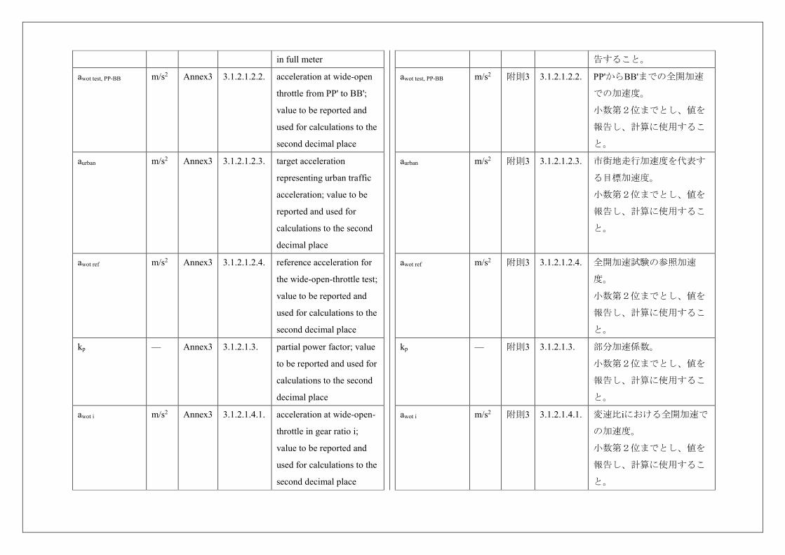
awot test m/s2 Annex3 3.1.2.1.2.1. acceleration at wide-open
throttle from AA' to BB';
value to be reported and
used for calculations to the
second decimal place
awot test,i m/s2 Annex3 3.1.2.1.2.1. acceleration at wide-open
throttle achieved in a
particular gear i; value to
be reported and used for
calculations to the second
decimal place
lpa m Annex3 3.1.2.1.2.1. point of depressing the
accelerator before line
AA'; value to be reported
5.1.参照)。小数第1位まで
とし、値を報告し、計算に
しようすること。
vPP’ km/h 附則3 3.1.2.1.2. 基準点がPP’を通過したとき
の車両速度(基準点の定義
については5.1.参照)。小数
第1位までとし、値を報告
し、計算にしようするこ
と。
awot test m/s2 附則3 3.1.2.1.2.1. AA'からBB'までの全開加速
での加速度。
小数第2位までとし、値を報
告し、計算に使用するこ
と。
awot test,i m/s2 附則3 3.1.2.1.2.1. 特定の変速段iで達成される
全開加速での加速度。
小数第2位までとし、値を
報告し、計算に使用するこ
と。
lpa m 附則3 3.1.2.1.2.1. AA'の前に加速装置を踏み
込む位置。
整数のm単位とし、値を報
in full meter
awot test, PP-BB m/s2 Annex3 3.1.2.1.2.2. acceleration at wide-open
throttle from PP' to BB';
value to be reported and
used for calculations to the
second decimal place
aurban m/s2 Annex3 3.1.2.1.2.3. target acceleration
representing urban traffic
acceleration; value to be
reported and used for
calculations to the second
decimal place
awot ref m/s2 Annex3 3.1.2.1.2.4. reference acceleration for
the wide-open-throttle test;
value to be reported and
used for calculations to the
second decimal place
kp — Annex3 3.1.2.1.3. partial power factor; value
to be reported and used for
calculations to the second
decimal place
awot i m/s2 Annex3 3.1.2.1.4.1. acceleration at wide-open-
throttle in gear ratio i;
value to be reported and
used for calculations to the
second decimal place
告すること。
awot test, PP-BB m/s2 附則3 3.1.2.1.2.2. PP'からBB'までの全開加速
での加速度。
小数第2位までとし、値を
報告し、計算に使用するこ
と。
aurban m/s2 附則3 3.1.2.1.2.3. 市街地走行加速度を代表す
る目標加速度。
小数第2位までとし、値を
報告し、計算に使用するこ
と。
awot ref m/s2 附則3 3.1.2.1.2.4. 全開加速試験の参照加速
度。
小数第2位までとし、値を
報告し、計算に使用するこ
と。
kp — 附則3 3.1.2.1.3. 部分加速係数。
小数第2位までとし、値を
報告し、計算に使用するこ
と。
awot i m/s2 附則3 3.1.2.1.4.1. 変速比iにおける全開加速で
の加速度。
小数第2位までとし、値を
報告し、計算に使用するこ
と。
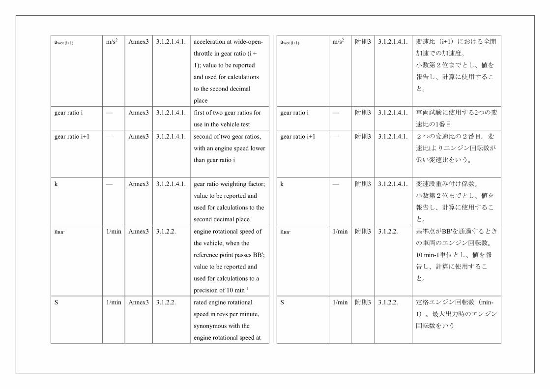
awot (i+1) m/s2 Annex3 3.1.2.1.4.1. acceleration at wide-open-
throttle in gear ratio (i +
1); value to be reported
and used for calculations
to the second decimal
place
gear ratio i — Annex3 3.1.2.1.4.1. first of two gear ratios for
use in the vehicle test
gear ratio i+1 — Annex3 3.1.2.1.4.1. second of two gear ratios,
with an engine speed lower
than gear ratio i
k — Annex3 3.1.2.1.4.1. gear ratio weighting factor;
value to be reported and
used for calculations to the
second decimal place
nBB’ 1/min Annex3 3.1.2.2. engine rotational speed of
the vehicle, when the
reference point passes BB';
value to be reported and
used for calculations to a
precision of 10 min-1
S 1/min Annex3 3.1.2.2. rated engine rotational
speed in revs per minute,
synonymous with the
engine rotational speed at
awot (i+1) m/s2 附則3 3.1.2.1.4.1. 変速比(i+1)における全開
加速での加速度。
小数第2位までとし、値を
報告し、計算に使用するこ
と。
gear ratio i — 附則3 3.1.2.1.4.1. 車両試験に使用する2つの変
速比の1番目
gear ratio i+1 — 附則3 3.1.2.1.4.1. 2つの変速比の2番目。変
速比iよりエンジン回転数が
低い変速比をいう。
k — 附則3 3.1.2.1.4.1. 変速段重み付け係数。
小数第2位までとし、値を
報告し、計算に使用するこ
と。
nBB’ 1/min 附則3 3.1.2.2. 基準点がBB'を通過するとき
の車両のエンジン回転数。
10 min-1単位とし、値を報
告し、計算に使用するこ
と。
S 1/min 附則3 3.1.2.2. 定格エンジン回転数(min-
1)。最大出力時のエンジン
回転数をいう
maximum power
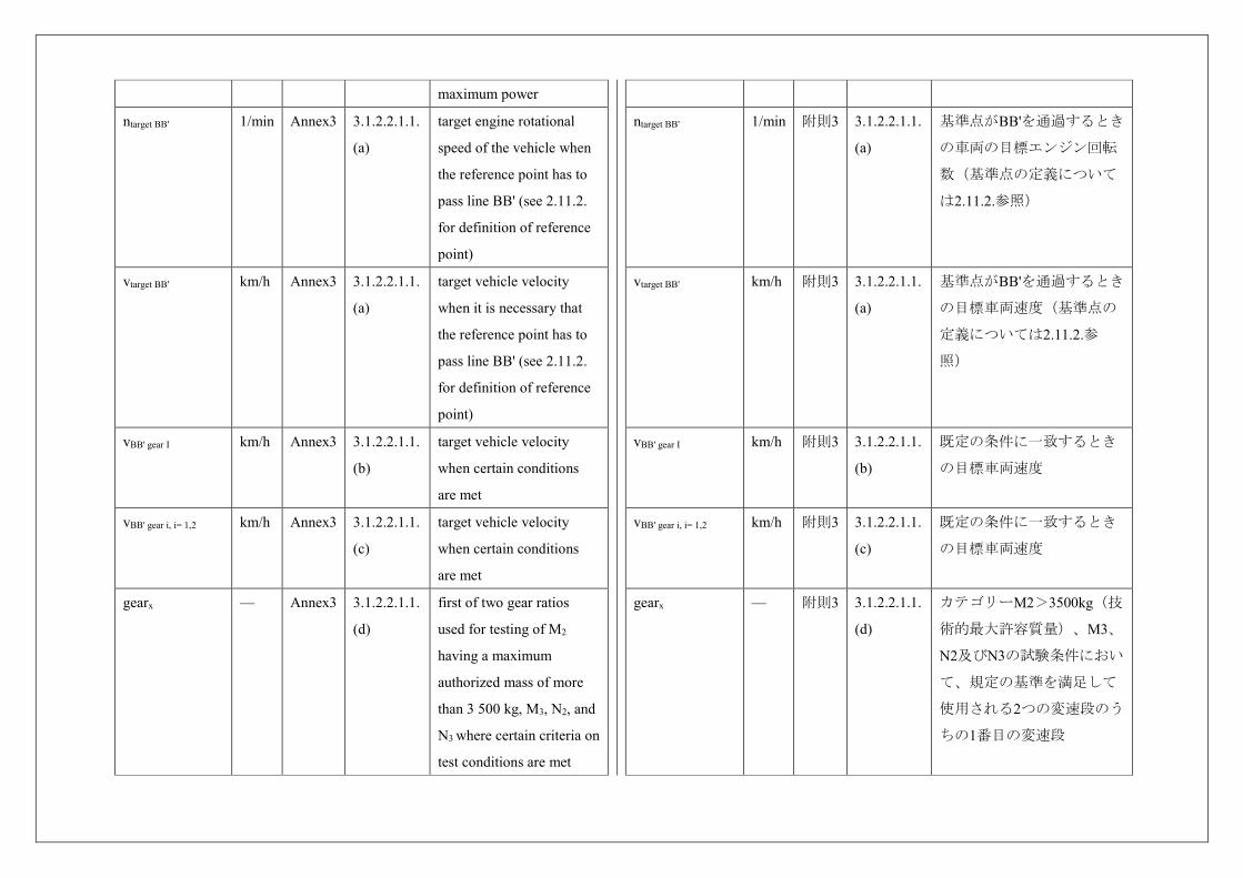
ntarget BB' 1/min Annex3 3.1.2.2.1.1.
(a)
target engine rotational
speed of the vehicle when
the reference point has to
pass line BB' (see 2.11.2.
for definition of reference
point)
vtarget BB' km/h Annex3 3.1.2.2.1.1.
(a)
target vehicle velocity
when it is necessary that
the reference point has to
pass line BB' (see 2.11.2.
for definition of reference
point)
vBB' gear I km/h Annex3 3.1.2.2.1.1.
(b)
target vehicle velocity
when certain conditions
are met
vBB' gear i, i= 1,2 km/h Annex3 3.1.2.2.1.1.
(c)
target vehicle velocity
when certain conditions
are met
gearx — Annex3 3.1.2.2.1.1.
(d)
first of two gear ratios
used for testing of M2
having a maximum
authorized mass of more
than 3 500 kg, M3, N2, and
N3 where certain criteria on
test conditions are met
ntarget BB' 1/min 附則3 3.1.2.2.1.1.
(a)
基準点がBB'を通過するとき
の車両の目標エンジン回転
数(基準点の定義について
は2.11.2.参照)
vtarget BB' km/h 附則3 3.1.2.2.1.1.
(a)
基準点がBB'を通過するとき
の目標車両速度(基準点の
定義については2.11.2.参
照)
vBB' gear I km/h 附則3 3.1.2.2.1.1.
(b)
既定の条件に一致するとき
の目標車両速度
vBB' gear i, i= 1,2 km/h 附則3 3.1.2.2.1.1.
(c)
既定の条件に一致するとき
の目標車両速度
gearx — 附則3 3.1.2.2.1.1.
(d)
カテゴリーM2>3500kg(技
術的最大許容質量)、M3、
N2及びN3の試験条件におい
て、規定の基準を満足して
使用される2つの変速段のう
ちの1番目の変速段
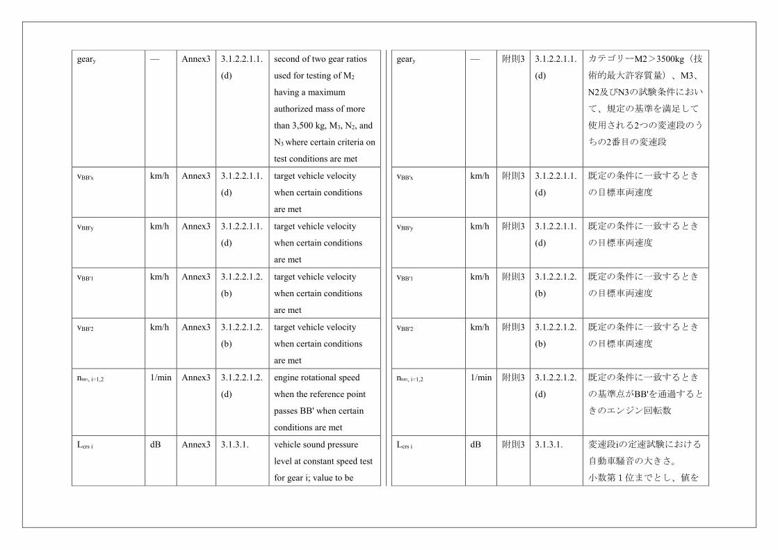
geary — Annex3 3.1.2.2.1.1.
(d)
second of two gear ratios
used for testing of M2
having a maximum
authorized mass of more
than 3,500 kg, M3, N2, and
N3 where certain criteria on
test conditions are met
vBB'x km/h Annex3 3.1.2.2.1.1.
(d)
target vehicle velocity
when certain conditions
are met
vBB'y km/h Annex3 3.1.2.2.1.1.
(d)
target vehicle velocity
when certain conditions
are met
vBB'1 km/h Annex3 3.1.2.2.1.2.
(b)
target vehicle velocity
when certain conditions
are met
vBB'2 km/h Annex3 3.1.2.2.1.2.
(b)
target vehicle velocity
when certain conditions
are met
nBB'i, i=1,2 1/min Annex3 3.1.2.2.1.2.
(d)
engine rotational speed
when the reference point
passes BB' when certain
conditions are met
Lcrs i dB Annex3 3.1.3.1. vehicle sound pressure
level at constant speed test
for gear i; value to be
geary — 附則3 3.1.2.2.1.1.
(d)
カテゴリーM2>3500kg(技
術的最大許容質量)、M3、
N2及びN3の試験条件におい
て、規定の基準を満足して
使用される2つの変速段のう
ちの2番目の変速段
vBB'x km/h 附則3 3.1.2.2.1.1.
(d)
既定の条件に一致するとき
の目標車両速度
vBB'y km/h 附則3 3.1.2.2.1.1.
(d)
既定の条件に一致するとき
の目標車両速度
vBB'1 km/h 附則3 3.1.2.2.1.2.
(b)
既定の条件に一致するとき
の目標車両速度
vBB'2 km/h 附則3 3.1.2.2.1.2.
(b)
既定の条件に一致するとき
の目標車両速度
nBB'i, i=1,2 1/min 附則3 3.1.2.2.1.2.
(d)
既定の条件に一致するとき
の基準点がBB'を通過すると
きのエンジン回転数
Lcrs i dB 附則3 3.1.3.1. 変速段iの定速試験における
自動車騒音の大きさ。
小数第1位までとし、値を
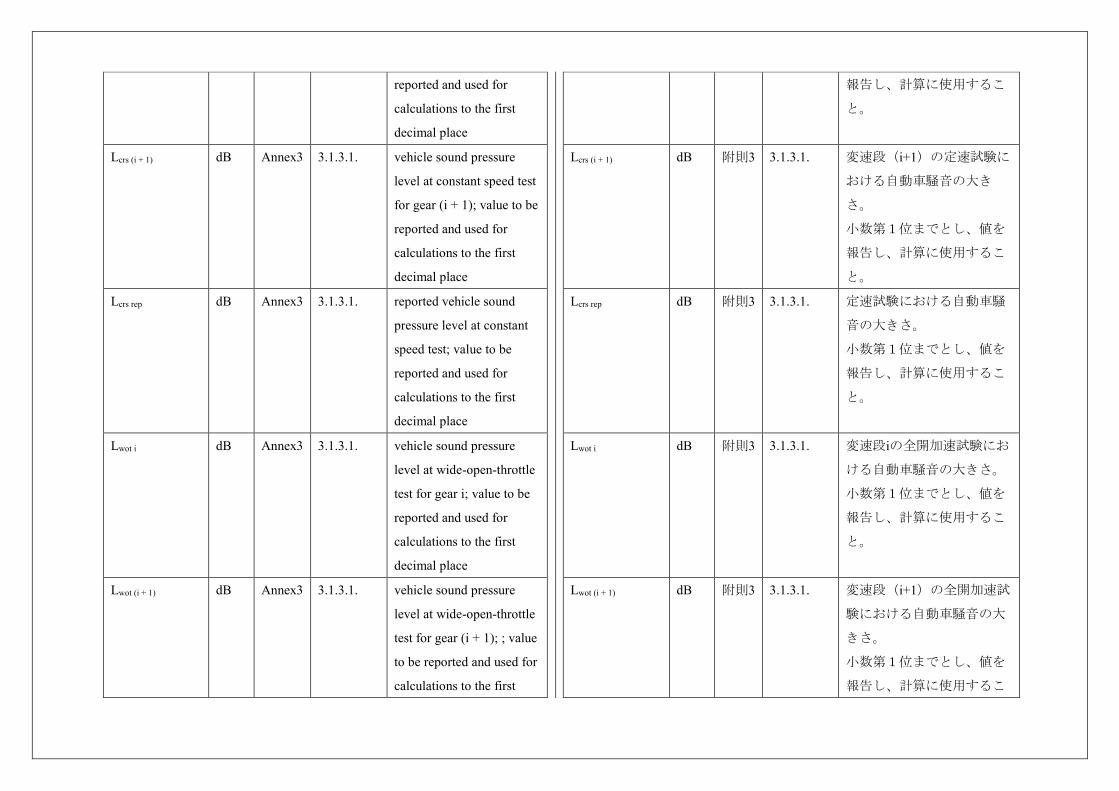
reported and used for
calculations to the first
decimal place
Lcrs (i + 1) dB Annex3 3.1.3.1. vehicle sound pressure
level at constant speed test
for gear (i + 1); value to be
reported and used for
calculations to the first
decimal place
Lcrs rep dB Annex3 3.1.3.1. reported vehicle sound
pressure level at constant
speed test; value to be
reported and used for
calculations to the first
decimal place
Lwot i dB Annex3 3.1.3.1. vehicle sound pressure
level at wide-open-throttle
test for gear i; value to be
reported and used for
calculations to the first
decimal place
Lwot (i + 1) dB Annex3 3.1.3.1. vehicle sound pressure
level at wide-open-throttle
test for gear (i + 1); ; value
to be reported and used for
calculations to the first
報告し、計算に使用するこ
と。
Lcrs (i + 1) dB 附則3 3.1.3.1. 変速段(i+1)の定速試験に
おける自動車騒音の大き
さ。
小数第1位までとし、値を
報告し、計算に使用するこ
と。
Lcrs rep dB 附則3 3.1.3.1. 定速試験における自動車騒
音の大きさ。
小数第1位までとし、値を
報告し、計算に使用するこ
と。
Lwot i dB 附則3 3.1.3.1. 変速段iの全開加速試験にお
ける自動車騒音の大きさ。
小数第1位までとし、値を
報告し、計算に使用するこ
と。
Lwot (i + 1) dB 附則3 3.1.3.1. 変速段(i+1)の全開加速試
験における自動車騒音の大
きさ。
小数第1位までとし、値を
報告し、計算に使用するこ
decimal place
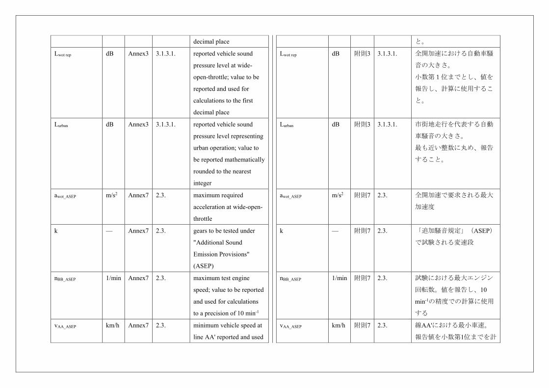
Lwot rep dB Annex3 3.1.3.1. reported vehicle sound
pressure level at wide-
open-throttle; value to be
reported and used for
calculations to the first
decimal place
Lurban dB Annex3 3.1.3.1. reported vehicle sound
pressure level representing
urban operation; value to
be reported mathematically
rounded to the nearest
integer
awot_ASEP m/s2 Annex7 2.3. maximum required
acceleration at wide-open-
throttle
k — Annex7 2.3. gears to be tested under
"Additional Sound
Emission Provisions"
(ASEP)
nBB_ASEP 1/min Annex7 2.3. maximum test engine
speed; value to be reported
and used for calculations
to a precision of 10 min-1
vAA_ASEP km/h Annex7 2.3. minimum vehicle speed at
line AA' reported and used
と。
Lwot rep dB 附則3 3.1.3.1. 全開加速における自動車騒
音の大きさ。
小数第1位までとし、値を
報告し、計算に使用するこ
と。
Lurban dB 附則3 3.1.3.1. 市街地走行を代表する自動
車騒音の大きさ。
最も近い整数に丸め、報告
すること。
awot_ASEP m/s2 附則7 2.3. 全開加速で要求される最大
加速度
k — 附則7 2.3. 「追加騒音規定」(ASEP)
で試験される変速段
nBB_ASEP 1/min 附則7 2.3. 試験における最大エンジン
回転数。値を報告し、10
min-1の精度での計算に使用
する
vAA_ASEP km/h 附則7 2.3. 線AA'における最小車速。
報告値を小数第1位までを計
for calculations to the first
decimal place
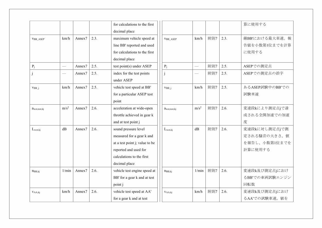
vBB_ASEP km/h Annex7 2.3. maximum vehicle speed at
line BB' reported and used
for calculations to the first
decimal place
Pj — Annex7 2.5. test point(s) under ASEP
j — Annex7 2.5. index for the test points
under ASEP
vBB_j km/h Annex7 2.5. vehicle test speed at BB'
for a particular ASEP test
point
awot,test,kj m/s2 Annex7 2.6. acceleration at wide-open
throttle achieved in gear k
and at test point j
Lwot,kj dB Annex7 2.6. sound pressure level
measured for a gear k and
at a test point j; value to be
reported and used for
calculations to the first
decimal place
nBB,kj 1/min Annex7 2.6. vehicle test engine speed at
BB' for a gear k and at test
point j
vAA,kj km/h Annex7 2.6. vehicle test speed at AA'
for a gear k and at test
算に使用する
vBB_ASEP km/h 附則7 2.3. 線BB'における最大車速。報
告値を小数第1位までを計算
に使用する
Pj — 附則7 2.5. ASEPでの測定点
j — 附則7 2.5. ASEPでの測定点の添字
vBB_j km/h 附則7 2.5. あるASEP試験中のBB'での
試験車速
awot,test,kj m/s2 附則7 2.6. 変速段kにより測定点jで達
成される全開加速での加速
度
Lwot,kj dB 附則7 2.6. 変速段kに対し測定点jで測
定される騒音の大きさ。値
を報告し、小数第1位までを
計算に使用する
nBB,kj 1/min 附則7 2.6. 変速段k及び測定点jにおけ
るBB'での車両試験エンジン
回転数
vAA,kj km/h 附則7 2.6. 変速段k及び測定点jにおけ
るAA'での試験車速。値を
point j; value to be
reported and used for
calculations to the first
decimal place
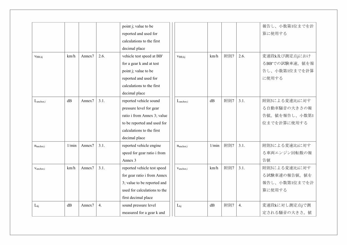
vBB,kj km/h Annex7 2.6. vehicle test speed at BB'
for a gear k and at test
point j; value to be
reported and used for
calculations to the first
decimal place
Lanchor,i dB Annex7 3.1. reported vehicle sound
pressure level for gear
ratio i from Annex 3; value
to be reported and used for
calculations to the first
decimal place
nanchor,i 1/min Annex7 3.1. reported vehicle engine
speed for gear ratio i from
Annex 3
vanchor,i km/h Annex7 3.1. reported vehicle test speed
for gear ratio i from Annex
3; value to be reported and
used for calculations to the
first decimal place
Lkj dB Annex7 4. sound pressure level
measured for a gear k and
報告し、小数第1位までを計
算に使用する
vBB,kj km/h 附則7 2.6. 変速段k及び測定点jにおけ
るBB'での試験車速。値を報
告し、小数第1位までを計算
に使用する
Lanchor,i dB 附則7 3.1. 附則3による変速比iに対す
る自動車騒音の大きさの報
告値。値を報告し、小数第1
位までを計算に使用する
nanchor,i 1/min 附則7 3.1. 附則3による変速比iに対す
る車両エンジン回転数の報
告値
vanchor,i km/h 附則7 3.1. 附則3による変速比iに対す
る試験車速の報告値。値を
報告し、小数第1位までを計
算に使用する
Lkj dB 附則7 4. 変速段kに対し測定点jで測
定される騒音の大きさ。値
at a test point j; value to be
reported and used for
calculations to the first
decimal place
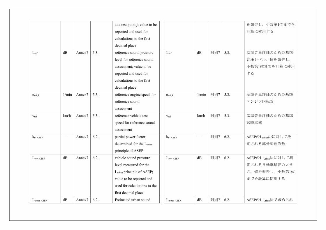
Lref dB Annex7 5.3. reference sound pressure
level for reference sound
assessment; value to be
reported and used for
calculations to the first
decimal place
nref_k 1/min Annex7 5.3. reference engine speed for
reference sound
assessment
vref km/h Annex7 5.3. reference vehicle test
speed for reference sound
assessment
kP_ASEP — Annex7 6.2. partial power factor
determined for the Lurban
principle of ASEP
Lwot ASEP dB Annex7 6.2. vehicle sound pressure
level measured for the
Lurban principle of ASEP;
value to be reported and
used for calculations to the
first decimal place
Lurban ASEP dB Annex7 6.2. Estimated urban sound
を報告し、小数第1位までを
計算に使用する
Lref dB 附則7 5.3. 基準音量評価のための基準
音圧レベル。値を報告し、
小数第1位までを計算に使用
する
nref_k 1/min 附則7 5.3. 基準音量評価のための基準
エンジン回転数
vref km/h 附則7 5.3. 基準音量評価のための基準
試験車速
kP_ASEP — 附則7 6.2. ASEPのLurban法に対して決
定される部分加速係数
Lwot ASEP dB 附則7 6.2. ASEPのL_Urban法に対して測
定される自動車騒音の大き
さ。値を報告し、小数第1位
までを計算に使用する
Lurban ASEP dB 附則7 6.2. ASEPのL_Urban法で求められ
pressure level determined
for the Lurban principle of
ASEP; value to be reported
and used for calculations
to the first decimal place
Lurban_measured_ASEP dB Annex7 6.2. interim result for
calculation of Lurban_ASEP;
value to be reported and
used for calculations to the
first decimal place
Lurban_normalized dB Annex7 6.2. interim result for
calculation of Lurban_ASEP;
value to be reported and
used for calculations to the
first decimal place
る推定市街地騒音の大き
さ。値を報告し、小数第1位
までを計算に使用する
Lurban_Measured_ASEP dB 附則7 6.2. L_Urban_ASEPの計算の中
間結果。値を報告し、小数
第1位までを計算に使用する
Lurban_Normalized dB 附則7 6.2. L_Urban_ASEPの計算の中
間結果。値を報告し、小数
第1位までを計算に使用する
3. Application for approval 3. 認可の申請
3.1. The application for approval of a vehicle type with regard to sound shall be
submitted by its manufacturer or by his duly accredited representative.
3.1. 音にかかわる車両型式の認可申請書は、自動車製作者等又はその正規の公
認代理人が提出するものとする。
3.2. It shall be accompanied by the undermentioned documents and the following
particulars in triplicate:
3.2. 認可申請書には、下記の書類及び下記の細目を3通添付するものとする。
3.2.1. A description of the vehicle type with regard to the items mentioned in
paragraph 2.2. above. The numbers and/or symbols identifying the engine type and
the vehicle type shall be specified;
3.2.1. 上記2.2項に明記した品目にかかわる車両型式の説明。原動機型式及び車
両型式を識別する数字・記号を明記するものとする。
3.2.2. A list of the components, duly identified, constituting the sound reduction
system;
3.2.2. 音低減システムを構成する、正式に特定された構成部品の一覧。
3.2.3. A drawing of the assembled sound reduction system and an indication of its 3.2.3. 組み立て済みの音低減システムの図面、及び同装置の車両における配置
position on the vehicle; の説明。
3.2.4. Detailed drawings of each component to enable it to be easily located and
identified, and a specification of the materials used.
3.2.4. 各構成部品の取付位置と識別が容易に判る詳細な図面、及び使用した材
料の仕様。
3.2.5. A technical information document including the information as outlined in
Annex 1, Appendix2.
3.2.5. 附則1の付録2で説明された情報を含んだ技術情報書面
3.3. In the case of paragraph 2.2.2. the single vehicle, representative of the type in
question, will be selected by the Technical Service conducting approval tests, in
accordance with the vehicle manufacturer, as that with the lowest mass in running
order with the shortest length and following the specification laid down in
paragraph 3.1.2.2. in Annex 3.
3.3. 2.2.2.により、認可試験を実施する技術機関は、附則3の3.1.2.2.に規定され
た仕様に従い、自動車製作者等と協議の上、最も短い車両長さで最も軽いラン
ニングオーダーの質量に関して、当該型式を代表する1つの車両を選択する。
3.4. At the request of the Technical Service conducting approval tests, the vehicle
manufacturer shall, in addition, submit a sample of the sound reduction system and
an engine of at least the same cylinder capacity and rated maximum net power as
that fitted to the vehicle in respect of which type-approval is sought.
3.4. 加えて、認可試験を実施する技術機関が要求した場合、自動車製作者等
は、当該音低減システムのサンプル並びに少なくとも型式認可が求められてい
る車両に取り付けられたものと同一の排気量及び定格最大出力を有する原動機
を提出するものとする。
3.5. The Type Approval Authority shall verify the existence of satisfactory
arrangements for ensuring effective control of the conformity of production before
type approval is granted.
3.5. 型式認可を行う行政官庁は、型式認可の付与に先立ち、生産の適合性に関
して効果的な管理を十分保障できるだけの体制が整っているかどうかを検証す
る。
4. Marking 4. マーキング
4.1. The components of the sound reduction system, excluding fixing hardware and
piping, shall bear:
4.1. 音低減システムの構成部品は、固定金具及び排気管を除き、以下を明記す
るものとする。
4.1.1. The trade name or mark of the manufacturer of the sound reduction system
and of its components; and
4.1.1. 音低減システム及びその構成部品の自動車製作者等の商号又は商標。及
び、
4.1.2. The manufacturer’s trade description; 4.1.2.自動車製作者等の商業表示。
4.2. These markings shall be clearly legible and be indelible even after fitting. 4.2. これらのマーキングは、取り付け後も明確に判読でき、かつ消えないもの
とする。
4.3. A component may carry several approval numbers if it has been approved as 4.3. 1つの構成部品が複数の交換用消音装置の構成部品として認可されている
component of several replacement silencing systems. 場合、複数の認可番号を明記してもよい。
5. Approval 5. 認可
5.1. Type approval shall only be granted if the vehicle type meets the requirements
of paragraphs 6. And 7. below.
5.1. 車両型式が下記6.及び7.の要件に適合する場合にのみ、型式認可を付与す
るものとする。
5.2. An approval number shall be assigned to each type approved. Its first two
digits (at present 03 corresponding to the 03 series of amendments) shall indicate
the series of amendments incorporating the most recent major technical
amendments made to the Regulation at the time of issue of the approval. The same
Contracting Party shall not assign the same number to another vehicle type.
5.2. 認可した各型式には認可番号を割り当てるものとする。その最初の2桁
(現在は、第3改訂版に対応して03)は、認可の発行時点において規則に加え
られている最新の主な技術的改訂を盛り込んだ改訂版を示すものとする。同一
締約国が、他の車両型式に同一番号を割り当てることはないものとする。
5.3. Notice of approval or of extension or of refusal or withdrawal of approval or of
production definitively discontinued of a vehicle type pursuant to this Regulation
shall be communicated to the Parties to the Agreement applying this Regulation, by
means of a form conforming to the model in Annex 1 to this Regulation.
5.3. 本規則に基づく車両型式の認可又は認可の拡大若しくは拒否若しくは取消
又は生産中止の通知は、本規則附則1の様式に適合する書式で、本規則を適用
している協定締約国に通知するものとする。
5.4. There shall be affixed, conspicuously and in a readily accessible place
specified on the approval form, to every vehicle conforming to a vehicle type
approved under this Regulation an international approval mark consisting of:
5.4. 本規則に基づいて認可された車両型式に適合する各車両には、以下のもの
から成る国際認可マークを、認可書式に規定された容易に確認できる場所に、
よく見えるように貼付するものとする。
5.4.1. A circle surrounding the letter “E” followed by the distinguishing number of
the country which has granted approval 2;
5.4.1. 「E」という文字の後に認可を付与した国*2の識別番号を続け、円で囲
む。 2 The distinguishing numbers of the Contracting Parties to the 1958 Agreement are
reproduced in Annex 3 to the Consolidated Resolution on the Construction of Vehicles
(R.E.3), document ECE/TRANS/WP.29/78/Rev. 3, Annex 3 -
www.unece.org/trans/main/wp29/wp29wgs/wp29gen/wp29resolutions.html
*2 1958年協定の締約国の識別番号は、車両構造統合決議(R.E.3)、文書
ECE/TRANS/WP.29/78/Rev.3の附則3
(www.unece.org/trans/main/wp29/wp29wgs/wp29gen/wp29resolutions.html)に再録されて
いる。
5.4.2. The number of this Regulation, followed by the letter “R”, a dash and the
approval number to the right of the circle prescribed in paragraph 5.4.1.
5.4.2. 5.4.1.に規定された円の右側に、本規則の番号を明記し、その後に文字
「R」、ダッシュ(「-」)及び認可番号を続ける。
5.5. If the vehicle conforms to a vehicle type approved, under one or more other
Regulations annexed to the Agreement, in the country which has granted approval
5.5. 当該車両が、本規則に基づいて認可を付与する国において、協定に付属す
る他の1つ又は複数の規則で認可された車両型式に適合する場合、5.4.1.に規定
under this Regulation, the symbol prescribed in paragraph 5.4.1. need not be
repeated; in such a case the regulation and approval numbers and the additional
symbols of all the Regulations under which approval has been granted in the
country which has granted approval under this Regulation shall be placed in
vertical columns to the right of the symbol prescribed in paragraph 5.4.1.
した記号は繰り返す必要はない。この場合、本規則に基づいて認可を付与する
国で認可を付与する根拠となった全ての規則の規則番号、認可番号及び追加記
号を、5.4.1.に規定した記号の右側に縦に並べるものとする。
5.6. The approval mark shall be clearly legible and be indelible. 5.6. 認可マークは、明確に判読でき、かつ消えないものとする。
5.7. The approval mark shall be placed close to or on the vehicle data plate affixed
by the manufacturer.
5.7. 認可マークは、自動車製作者等の添付する車両データプレート内か、その
近くに配置するものとする。
5.8. Annex 2 to this Regulation gives examples of arrangements of the approval
mark.
5.8. 本規則附則2に認可マークの配置例を示す。
6. Specifications 6. 仕様
6.1. General specifications 6.1. 一般仕様
6.1.1. The vehicle, its engine and its sound reduction system shall be so designed,
constructed and assembled as to enable the vehicle, in normal use, despite the
vibration to which it may be subjected, to comply with the provisions of this
Regulation.
6.1.1. 車両、原動機及び音低減システムは、通常の使用状態において車両が振
動を受けても、本規則の規定に適合できるような設計、構造及び組み立てであ
るものとする。
6.1.2. The sound reduction system shall be so designed, constructed and assembled
as to be able to reasonably resist the corrosive phenomena to which it is exposed
having regard to the conditions of use of the vehicle, including regional climate
differences.
6.1.2. 音低減システムは、地域的な気候の違いを含め、車両の使用条件を考慮
して、当該装置が受ける腐食作用に無理なく耐えることができるような設計、
構造及び組み立てであるものとする。
6.2. Specifications regarding sound level 6.2.騒音の大きさにかかわる仕様
6.2.1. Methods of measurement 6.2.1. 測定方法
6.2.1.1. The sound made by the vehicle type submitted for approval shall be
measured by the methods described in Annex 3 to this Regulation for the vehicle in
motion and for the vehicle when stationary 3; in the case of a vehicle where an
internal combustion engine cannot operate when the vehicle is stationary, the
6.2.1.1. 認可用に提出された車両から発生する音は、走行中及び停止中*3につい
て、本規則の附則3に規定された方法を用いて測定するものとする。車両の停
止中に内燃機関が作動しない車両の場合、発生する音は走行中にのみ測定する
ものとする。車両の停止中に内燃機関が作動しないカテゴリーM1のハイブリッ
emitted sound shall only be measured in motion. In the case of a hybrid electrical
vehicle of category M1 where an internal combustion engine cannot operate when
the vehicle is stationary, the emitted sound shall be measured according to Annex
3, paragraph 4.
Vehicles having a technically maximum permissible laden mass exceeding 2,800
kg shall be subjected to an additional measurement of the compressed air noise
with the vehicle stationary in accordance with the specifications of Annex 5, if the
corresponding brake equipment is part of the vehicle.
ド電気自動車については、発生する音は附則3の4項に従って測定するものとす
る。
技術的最大許容質量が2,800 kgを超えるものであって、空気式制動装置を備え
る車両にあっては、附則5に従って停止中の車両で圧縮空気騒音の追加測定を
行うものとする。
3 A test is made on a stationary vehicle in order to provide a reference value for
administrations which use this method to check vehicles in use.
*3 この方法を用いて使用過程の車両を検査する行政官庁の基準値とするために、試験
を行なう。
6.2.1.2. The values measured in accordance with the provisions of paragraph
6.2.1.1. above shall be entered in the test report and a certificate corresponding to
the model shown in Annex 1.
6.2.1.2. 上記6.2.1.1.の規定に従って測定した値は、試験結果成績書と附則1に示
す認可証に記入するものとする。
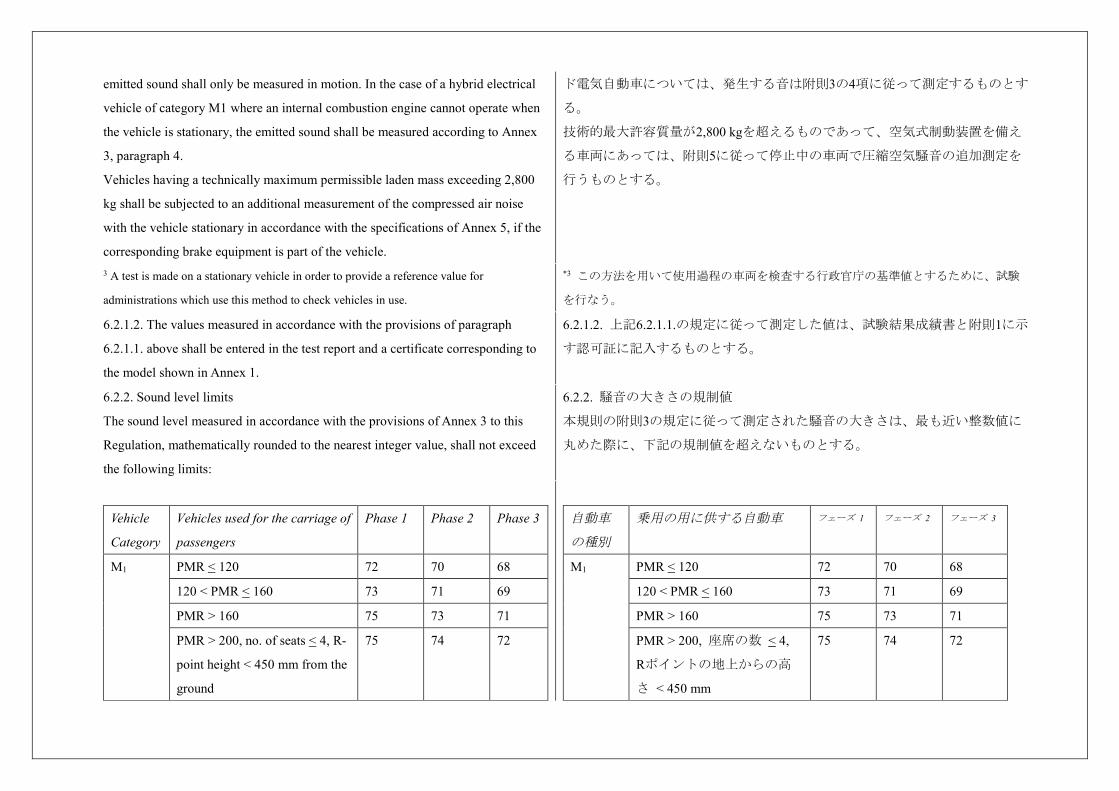
6.2.2. Sound level limits
The sound level measured in accordance with the provisions of Annex 3 to this
Regulation, mathematically rounded to the nearest integer value, shall not exceed
the following limits:
6.2.2. 騒音の大きさの規制値
本規則の附則3の規定に従って測定された騒音の大きさは、最も近い整数値に
丸めた際に、下記の規制値を超えないものとする。
Vehicle
Category
Vehicles used for the carriage of
passengers
Phase 1 Phase 2 Phase 3
M1 PMR < 120 72 70 68
120 < PMR < 160 73 71 69
PMR > 160 75 73 71
PMR > 200, no. of seats < 4, R-
point height < 450 mm from the
ground
75 74 72
自動車
の種別
乗用の用に供する自動車 フェーズ 1 フェーズ 2 フェーズ 3
M1 PMR < 120 72 70 68
120 < PMR < 160 73 71 69
PMR > 160 75 73 71
PMR > 200, 座席の数 < 4,
Rポイントの地上からの高
さ < 450 mm
75 74 72
M2 M < 2.5 t 72 70 69
2.5 t < M < 3.5 t 74 72 71
M > 3.5 t; Pn < 135 kW 75 73 72
M > 3.5 t; Pn > 135 kW 75 74 72
M3 Pn < 150 kW 76 74 73
150 kW < Pn < 250 kW 78 77 76
Pn > 250 kW 80 78 77
Vehicle
Category
Vehicles used for the carriage of
goods
Phase 1 Phase 2 Phase 3
N1 M < 2.5 t 72 71 69
M > 2.5 t 74 73 71
N2 Pn < 135 kW 77 75 74
Pn > 135 kW 78 76 75
N3 Pn < 150 kW 79 77 76
150 kW < Pn < 250 kW 81 79 77
Pn > 250 kW 82 81 79
M2 M < 2.5 t 72 70 69
2.5 t < M < 3.5 t 74 72 71
M > 3.5 t; Pn < 135 kW 75 73 72
M > 3.5 t; Pn > 135 kW 75 74 72
M3 Pn < 150 kW 76 74 73
150 kW < Pn < 250 kW 78 77 76
Pn > 250 kW 80 78 77
自動車
の種別
貨物の運送の用に供する自
動車
フェーズ 1 フェーズ 2 フェーズ 3
N1 M < 2.5 t 72 71 69
M > 2.5 t 74 73 71
N2 Pn < 135 kW 77 75 74
Pn > 135 kW 78 76 75
N3 Pn < 150 kW 79 77 76
150 kW < Pn < 250 kW 81 79 77
Pn > 250 kW 82 81 79
6.2.2.1. For vehicle types of category M1 derived from N1 vehicle types having a
technically permissible maximum laden mass above 2.5 tons and a R-point height
greater than 850 mm from the ground, the limits of vehicles types of category N1
having a technically permissible maximum laden mass above 2.5 tons apply.
6.2.2.1. 技術的最大許容質量が2.5トンを超え、地面からのRポイントの高さが
850 mmを超える車両型式N1から派生したカテゴリーM1の車両については、技
術的最大許容質量が2.5トンを超えるカテゴリーN1の車両の規制値が適用され
る。
6.2.2.2. For vehicle types designed for off-road 4 use, the limit values shall be
increased by 2 dB(A) for M3 and N3 vehicles category and 1 dB(A) for any other
vehicle category.
For vehicle types of category M1 the increased limit values for off-road vehicles are
only valid if the technically permissible maximum laden mass > 2 tons.
6.2.2.2. オフロード 用*4に設計された車両は、M3及びN3の車両カテゴリーにつ
いては2 dB(A)、その他の車両カテゴリーについては1 dB(A)、規制値を引
き上げるものとする。
カテゴリーM1の車両については、技術的最大許容質量が2トンを超える場合の
み、オフロード車両用に引き上げられた規制値を適用する。 4 As defined in the Consolidated Resolution on the Construction of Vehicles (R.E.3.), *4 車両構造統合決議(R.E.3)、文書 ECE/TRANS/WP.29/78/Rev.3、2.
document ECE/TRANS/WP.29/78/Rev.3, para. 2 -
www.unece.org/trans/main/wp29/wp29wgs/wp29gen/wp29resolutions.html
(www.unece.org/trans/main/wp29/wp29wgs/wp29gen/wp29resolutions.html)に記載の通
り。
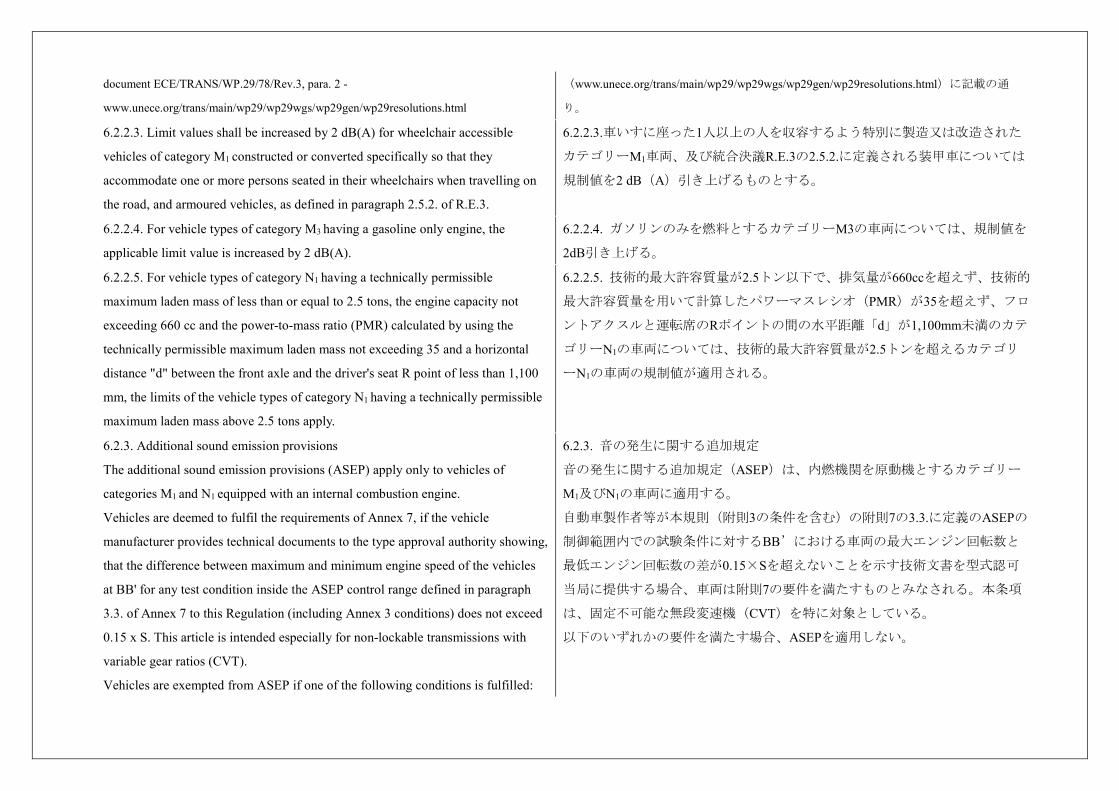
6.2.2.3. Limit values shall be increased by 2 dB(A) for wheelchair accessible
vehicles of category M1 constructed or converted specifically so that they
accommodate one or more persons seated in their wheelchairs when travelling on
the road, and armoured vehicles, as defined in paragraph 2.5.2. of R.E.3.
6.2.2.3.車いすに座った1人以上の人を収容するよう特別に製造又は改造された
カテゴリーM1車両、及び統合決議R.E.3の2.5.2.に定義される装甲車については
規制値を2 dB(A)引き上げるものとする。
6.2.2.4. For vehicle types of category M3 having a gasoline only engine, the
applicable limit value is increased by 2 dB(A).
6.2.2.4. ガソリンのみを燃料とするカテゴリーM3の車両については、規制値を
2dB引き上げる。
6.2.2.5. For vehicle types of category N1 having a technically permissible
maximum laden mass of less than or equal to 2.5 tons, the engine capacity not
exceeding 660 cc and the power-to-mass ratio (PMR) calculated by using the
technically permissible maximum laden mass not exceeding 35 and a horizontal
distance "d" between the front axle and the driver's seat R point of less than 1,100
mm, the limits of the vehicle types of category N1 having a technically permissible
maximum laden mass above 2.5 tons apply.
6.2.2.5. 技術的最大許容質量が2.5トン以下で、排気量が660ccを超えず、技術的
最大許容質量を用いて計算したパワーマスレシオ(PMR)が35を超えず、フロ
ントアクスルと運転席のRポイントの間の水平距離「d」が1,100mm未満のカテ
ゴリーN1の車両については、技術的最大許容質量が2.5トンを超えるカテゴリ
ーN1の車両の規制値が適用される。
6.2.3. Additional sound emission provisions
The additional sound emission provisions (ASEP) apply only to vehicles of
categories M1 and N1 equipped with an internal combustion engine.
Vehicles are deemed to fulfil the requirements of Annex 7, if the vehicle
manufacturer provides technical documents to the type approval authority showing,
that the difference between maximum and minimum engine speed of the vehicles
at BB' for any test condition inside the ASEP control range defined in paragraph
3.3. of Annex 7 to this Regulation (including Annex 3 conditions) does not exceed
0.15 x S. This article is intended especially for non-lockable transmissions with
variable gear ratios (CVT).
Vehicles are exempted from ASEP if one of the following conditions is fulfilled:
6.2.3. 音の発生に関する追加規定
音の発生に関する追加規定(ASEP)は、内燃機関を原動機とするカテゴリー
M1及びN1の車両に適用する。
自動車製作者等が本規則(附則3の条件を含む)の附則7の3.3.に定義のASEPの
制御範囲内での試験条件に対するBB’における車両の最大エンジン回転数と
最低エンジン回転数の差が0.15×Sを超えないことを示す技術文書を型式認可
当局に提供する場合、車両は附則7の要件を満たすものとみなされる。本条項
は、固定不可能な無段変速機(CVT)を特に対象としている。
以下のいずれかの要件を満たす場合、ASEPを適用しない。
(a) For vehicles of category N1, if the engine capacity does not exceed 660 cc and
the power-to-mass ratio PMR calculated by using the technically permissible
maximum laden mass does not exceed 35.
(a) カテゴリーN1の車両について、排気量が660 ccを超えず、技術的最大許容
質量を用いて計算したパワーマスレシオ(PMR)が35を超えない場合。
(b) For vehicles of category N1, if the payload is at least 850 kg and the power-to-
mass ratio calculated by using the technically permissible maximum laden mass
does not exceed 40.
(b) カテゴリーN1の車両について、最大積載量が850kg以上で、技術的最大許容
質量を用いて計算したパワーマスレシオが40を超えない場合。
(c) For vehicles of category N1 or M1 derived from N1 if the technically permissible
maximum laden mass is greater than 2.5 tons and the R-point height is greater than
850 mm from the ground and the power- to-mass ratio calculated by using the
technically permissible maximum laden mass does not exceed 40.
(c) カテゴリーN1又はN1から派生したカテゴリーM1の車両について、技術的最
大許容質量が2.5トンを超えるとともに、地面からのRポイントの高さが850mm
を超え、技術的最大許容質量を用いて計算したパワーマスレシオが40を超えな
い場合。
The sound emission of the vehicle under typical on-road driving conditions, which
are different from those under which the type-approval test set out in Annex 3 and
Annex 7 was carried out, shall not deviate from the test result in a significant
manner.
附則3及び附則7に記載の型式認可試験が実施された条件とは異なる標準的な路
上走行条件下での車両の音の発生は、試験結果から大きく逸脱しないものとす
る。
6.2.3.1. The vehicle manufacturer shall not intentionally alter, adjust, or introduce
any mechanical, electrical, thermal, or other device or procedure solely for the
purpose of fulfilling the sound emission requirements as specified under this
Regulation which is not operational during typical on-road operation.
6.2.3.1. 自動車製作者等は、本規則で規定されている音の発生に関する要件を
満たす目的のためだけに、通常の路上運転中に使用しない機械装置、電気装
置、熱装置、、その他装置又は手順を意図的に改造、調整又は導入しないもの
とする。
6.2.3.2. The vehicle shall meet the requirements of Annex 7 to this Regulation. 6.2.3.2. 車両は本規則の附則7の要件を満たすものとする。
6.2.3.3. In applying for type approval, the manufacturer shall provide a statement,
in conformity with the Appendix of Annex 7, that the vehicle type to be approved
complies with the requirements of paragraph 6.2.3. of this Regulation.
6.2.3.3. 型式認可の申請をする際、自動車製作者等は、附則7の付録1に従っ
て、認可される車両型式が本規則の6.2.3.の要件に適合しているとする宣言書
を提出する。
6.3. Specifications regarding exhaust systems containing fibrous materials 6.3. 繊維性材料を含んだ排気システムにかかわる仕様
6.3.1. Requirements of Annex 4 shall be applied. 6.3.1. 附則4の要件を適用するものとする。
7. Modification and extension of approval 7. 車両型式の変更及び認可の拡大
7.1. Every modification of the vehicle type shall be notified to the Type Approval 7.1. 車両型式の変更を行なうごとに、当該車両型式を認可した型式認可当局に
Authority which approved the vehicle type. The Type Approval Authority may then
either:
申請をするものとする。型式認可当局は以下のうちいずれかを行うことができ
る。
7.1.1. Consider that the modifications made are unlikely to have an appreciable
adverse effect and that in any case the vehicle still complies with the requirements,
or
7.1.1. 実施された変更によって著しい悪影響は生じず、車両は従来通り要件に
適合すると判断する。又は、
7.1.2. Require a further test report from the Technical Service responsible for
conducting the tests.
7.1.2. 試験の実施する技術機関に追加試験結果を要求する。
7.2. Confirmation or refusal of approval, specifying the alterations shall be
communicated by the procedure specified in paragraph 5.3. above to the Parties to
the Agreement applying this Regulation.
7.2. 認可又は拒否をした際には、変更点を明記して、上記5.3.に規定した手順
で、(型式認可当局は)本規則を適用する協定締約国に通知するものとする。
7.3. The Type Approval Authority issuing the extension of approval shall assign a
series number for such an extension and inform thereof the other Parties to the
1958 Agreement applying this Regulation by means of a communication form
conforming to the model in Annex 1 to this Regulation.
7.3. 認可の拡大を発行する型式認可当局は、拡大内容に対して通し番号を割り
当て、本規則附則1に示す通知書で、本規則を適用している他の1958年協定締
約国にその旨を通知するものとする。
8. Conformity of production 8. 生産の適合性
The conformity of production procedures shall comply with those set out in the
Agreement, Appendix 2 (E/ECE/324-E/ECE/TRANS/505/Rev.2) with the
following requirements:
生産の適合性に関する手順は、下記の要件とともに、協定規則の付録2
(E/ECE/324-E/ECE/TRANS/505/Rev.2)に定める手順に適合しなければならな
い。
8.1. Vehicles approved according to this Regulation shall be so manufactured as to
conform to the type approved by meeting the requirements of paragraph 6. above.
8.1. 本規則に従って認可された車両は、上記6.に規定された要件を満たして、
認可された型式に適合するように製造されなければならない。
8.2. The minimum requirements for conformity of production control procedures of
Annex 6 to this Regulation shall be complied with.
8.2. 本規則の附則6に定める生産の適合性管理手順の最低要件に適合しなけれ
ばならない。
8.3. The authority which has granted type approval may at any time verify the
conformity control methods applied in each production facility. The normal
frequency of these verifications shall be one every two years.
8.3. 型式認可を付与した当局は、いつでも各生産施設で適用されている適合性
管理方法を検証することができる。これらの検証の通常頻度は、2年に1回とす
る。
9. Penalties for non-conformity of production 9. 生産の不適合に対する罰則
9.1. The approval granted in respect of a vehicle type pursuant to this Regulation
may be withdrawn if the requirements set forth above are not met.
9.1. 本規則に従って車両型式に付与された認可は、上記要件が満たされていな
い場合、これを取り消すことができる。
9.2. If a Contracting Party to the Agreement applying this Regulation withdraws an
approval it has previously granted, it shall forthwith so notify the other Contracting
Parties applying this Regulation, by means of a communication form conforming
to the model in Annex 1 to this Regulation.
9.2. 本規則を適用する協定締約国が以前に付与した認可を取り消す場合、本規
則を適用する他の協定締約国に対して、本規則の附則1に示す通知書によって
これを速やかに通知するものとする。
10. Production definitively discontinued 10. 生産中止
10.1. If the holder of the approval completely ceases to manufacture a vehicle type
approved in accordance with this Regulation, he shall so inform the authority
which granted the approval. Upon receiving the relevant communication that
authority shall inform thereof the other Parties to the 1958 Agreement applying this
Regulation by means of a communication form conforming to the model in Annex
1 to this Regulation.
10.1. 認可を受けた自動車製作者等が本規則に従って認可された型式の車両の
生産を完全に停止する場合、認可を付与した当局にその旨を届け出なければな
らない。当該届け出を受けしだい、当局は本規則を適用する他の協定締約国
に、本規則の附則1 に示す通知書によってその旨を通知しなければならない。
11. Transitional provisions 11. 過渡規定
11.1. As from the official date of entry into force of the 03 series of amendments to
this Regulation, no Contracting Party applying this Regulation shall refuse to grant
or refuse to accept type-approvals under this Regulation as amended by the 03
series of amendments.
11.1. 本協定規則の第3改訂版の正式発効日以降、本協定規則を適用する締約国
は、第3改訂版で改訂した本協定規則に基づく型式認可の付与又は受理を拒否
しないものとする。
11.2. Transitional Provisions for Phase 1 (see paragraph 6.2.2. above) 11.2. フェーズ1の過渡規定(本協定規則の6.2.2.を参照)
11.2.1. As from 1 July 2016, Contracting Parties applying this Regulation shall
grant type-approvals only if the vehicle type to be approved meets the requirements
of phase 1 (see paragraph 6.2.2. above) of this Regulation as amended by the 03
series of amendments. As from the official date of entry into force of the 03 series of amendments,
Contracting Parties applying this Regulation shall grant type approvals to the
11.2.1. 2016年7月1日以降、本協定規則を適用する締約国は、認可される車両型
式が第3改訂版で改訂した本協定規則のフェーズ1(本協定規則の6.2.2.を参
照)の要件を満たす場合のみ、型式認可を付与するものとする。
さらに、第3改訂版の正式発効日以降、本協定規則を適用する締約国は、第3改
訂版で改訂した本協定規則フェーズ2又はフェーズ3の要件を満たす車両型式に
型式認可を付与するものとする。
vehicle type which meets the requirements of phase 2 or phase 3 of this Regulation
as amended by the 03 series of amendments.
11.2.2. Contracting Parties applying this Regulation shall not refuse to grant
extensions of type approvals for existing types which have been granted according
to the 02 series of amendments to this Regulation.
11.2.2. 本協定規則を適用する締約国は、本協定規則の第2改訂版に従って付与
された既存の型式の型式認可の拡大の付与を拒否しないものとする。
11.2.3. Until 30 June 2022, no Contracting Party applying this Regulation shall
refuse national or regional type approval of a vehicle type-approved to the 02 series
of amendments to this Regulation.
11.2.3. 2022年6月30日まで、本規則を適用する締約国は、本規則の第2改訂版に
従って型式認可された車両の国内又は地域型式認可を拒否しないものとする。
11.2.4. As from 1 July 2022, Contracting Parties applying this Regulation shall not
be obliged to accept for the purpose of national or regional type approval, a vehicle
type approved to the preceding series of amendments to this Regulation.
11.2.4. 2022年7月1日以降、本協定規則を適用する締約国は、本協定規則の先行
改訂版に従って認可された車両型式を、国内又は地域型式認可のために受理す
る義務を負わないものとする。
11.2.5. Even after the date of entry into force of the 03 series of amendments to this
Regulation, Contracting Parties applying this Regulation may continue for national
or regional purposes granting type approvals and extensions of type approvals to
the preceding series of amendments to this Regulation.
11.2.5. 本協定規則の第3改訂版の発効日後も、本協定規則を適用する締約国
は、国内又は地域の事情により本協定規則の先行改訂版に従った型式認可及び
型式認可の拡大の付与を継続してもよい。
11.3. Transitional Provisions for Phase 2 (see paragraph 6.2.2. above) 11.3. フェーズ2の過渡規定(本協定規則の6.2.2.を参照)
11.3.1. As from 1 July 2020 for vehicle types other than N2 and as from 1 July
2022 for vehicles types of category N2, Contracting Parties applying this
Regulation shall grant type approvals only if the vehicle type to be approved meets
the requirements of phase 2 (see paragraph 6.2.2. above) of this Regulation as
amended by the 03 series of amendments.
Furthermore, as from the official date of entry into force of the 03 series of
amendments, Contracting Parties applying this Regulation shall grant type
approvals to the vehicle type which meets the requirements of phase 3 of this
Regulation as amended by the 03 series of amendments.
11.3.1. カテゴリN2以外の車両型式については2020年7月1日以降、カテゴリー
N2の車両型式については2022年7月1日以降、本協定規則を適用する締約国は、
認可される車両型式が第3改訂版で改訂した本協定規則のフェーズ2(本協定規
則の6.2.2.を参照)の要件を満たす場合のみ、型式認可を付与するものとす
る。
さらに、第3改訂版の正式発効日以降、本協定規則を適用する締約国は、第3改
訂版で改訂した本協定規則のフェーズ3の要件を満たす車両型式に型式認可を
付与するものとする。
11.3.2. Contracting Parties applying this Regulation shall not refuse to grant 11.3.2. 本協定規則を適用する締約国は、本協定規則のフェーズ1(本協定規則
extensions of type approvals for existing types which have been granted according
to phase 1 (see paragraph 6.2.2. above) or the 02 series of amendments to this
Regulation.
の6.2.2.を参照)又は第2改訂版に従って付与された既存の型式の型式認可の拡
大の付与を拒否しないものとする。
11.3.3. Until 30 June 2022 for vehicle types other than N2 and until 30 June 2023
for vehicles types of category N2, no Contracting Party applying this Regulation
shall refuse national or regional type approval of a vehicle type-approved to phase
1 (see paragraph 6.2.2. above) or the 02 series of amendments to this Regulation.
11.3.3. N2以外の車両型式については2022年6月30日まで、またカテゴリーN2の
車両型式については2023年6月30日まで、本規則を適用する締約国は、本規則
のフェーズ1(上記6.2.2.を参照)又は第2改訂版に従って型式認可された車両
の国内又は地域型式認可を拒否しないものとする。
11.3.4. As from 1 July 2022 for vehicle types other than N2 and as from 1 July
2023 for vehicles types of category N2, Contracting Parties applying this
Regulation shall not be obliged to accept for the purpose of national or regional
type approval, a vehicle type approved to phase 1 (see paragraph 6.2.2.1. above) or
the preceding series of amendments to this Regulation.
11.3.4. N2以外の車両型式については2022年7月1日以降、及びカテゴリーN2の車
両型式については2023年7月1日以降、本協定規則を適用する締約国は、本協定
規則のフェーズ1(本規則の6.2.2.1.を参照)又は先行改訂版に従って認可され
た車両型式を、国内又は地域型式認可のために受理する義務を負わないものと
する。
11.3.5. Even after the date of entry into force of the 03 series of amendments to this
Regulation, Contracting Parties applying this Regulation may continue for national
or regional purposes granting type approvals and extensions of type approvals to
phase 1 (see paragraph 6.2.2. above) or the prededing series of amendments to this
Regulation.
11.3.5. 本協定規則の第3改訂版の発効日後も、本協定規則を適用する締約国
は、国内又は地域の事情により本協定規則のフェーズ1(本規則の6.2.2.を参
照)又は第2改訂版に従った型式認可及び型式認可の拡大の付与を継続しても
よい。
11.4. Transitional Provisions for Phase 3 (see paragraph 6.2.2. above) 11.4. フェーズ3の過渡規定(本協定規則の6.2.2.を参照)
11.4.1. As from 1 July 2024 for vehicle types other than N2, N3 and M3 and as from
1 July 2026 for vehicles types of category N2, N3 and M3, Contracting Parties
applying this Regulation shall grant type-approvals only if the vehicle type to be
approved meets the requirements of phase 3 (see paragraph 6.2.2. above) of this
Regulation as amended by the 03 series of amendments.
11.4.1. カテゴリーN2、N3及びM3以外の車両型式については2024年7月1日以
降、カテゴリーN2、N3及びM3の車両型式については2026年7月1日以降、本協
定規則を適用する締約国は、認可される車両型式が第3改訂版で改訂した本協
定規則のフェーズ3(本協定規則の6.2.2.を参照)の要件を満たす場合のみ、型
式認可を付与するものとする。
11.4.2. Contracting Parties applying this Regulation shall not refuse to grant
extensions of type approvals for existing types which have been granted according
to phase 2 according to paragraph 6.2.2. above.
11.4.2. 本協定規則を適用する締約国は、本規則の6.2.2.のフェーズ2に従って付
与された既存の型式の型式認可の拡大の付与を拒否しないものとする。
11.4.3. Until 30 June 2026 for vehicle types other than N2, N3 and M3 anduntil 30
June 2027 for vehicles types of category N2, N3 and M3, no Contracting Party
applying this Regulation shall refuse national or regional type approval of a vehicle
type-approved to phase 2 according to paragraph 6.2.2. above.
11.4.3. カテゴリーN2、N3及びM3以外の車両型式については2026年6月30日ま
で、またカテゴリーN2、N3及びM3の車両型式については2027年6月30日まで、
本規則を適用する締約国は、上記6.2.2.のフェーズ2に従って型式認可された車
両の国内又は地域型式認可を拒否しないものとする。
11.4.4. As from 1 July 2026 for vehicle types other than N2, N3 and M3 and as from
1 July 2027 for vehicles types of category N2, N3 and M3, Contracting Parties
applying this Regulation shall not be obliged to accept for the purpose of national
or regional type approval, a vehicle type approved to phase 2 according to
paragraph 6.2.2. above.
11.4.4. カテゴリーN2、N3及びM3以外の車両型式については2026年7月1日以
降、及びカテゴリーN2、N3M3の車両型式については2027年7月1日以降、本協
定規則を適用する締約国は、本協定規則6.2.2.のフェーズ2に従って認可された
車両型式を、国内又は地域型式認可のために受理する義務を負わないものとす
る。
11.4.5. Even after the date of entry into force of the 03 series of amendments to this
Regulation, Contracting Parties applying this Regulation may continue for national
or regional purposes granting type approvals and extensions of type approvals to
phase 1 or phase 2 (see paragraph 6.2.2. above) or the preceding series of
amendments to this Regulation.
11.4.5. 本協定規則の第3改訂版の発効日後も、本協定規則を適用する締約国
は、国内又は地域の事情により本協定規則のフェーズ1又はフェーズ2(本規則
の6.2.2.を参照)又は先行改訂版に従った型式認可及び型式認可の拡大の付与
を継続してもよい。
11.5. Notwithstanding the transitional provisions above, Contracting Parties whose
application of this Regulation comes into force after the date of entry into force of
the most recent series of amendments are not obliged to accept type approvals
which were granted in accordance with any of the preceding series of amendments
to this Regulation.
11.5. 上記過渡規定にかかわらず、最新の改訂版の発効日後に本協定規則の適
用が効力を発する締約国は、本協定規則の先行改訂版のいずれかに従って付与
された型式認可を受理する義務を負わない。
11.6. Until 30 June 2019, vehicles with a serial hybrid drive train which have a
combustion engine with no mechanical coupling to the power train are excluded
from the requirements of paragraph 6.2.3. above.
11.6. 2019年6月30日までは、パワートレーンに機械的に連結していない内燃機
関を原動機とするシリーズハイブリッドドライブトレーンを有する車両は、
6.2.3.の要件から除外される。
11.7. Until 30 June 2019, Contracting Parties applying this Regulation can
continue to grant approvals using test sites which comply with the specifications of
the preceding series of amendments to this Regulation as an alternative to Annex 3,
paragraph 2.1. of this Regulation.
11.7. 2019年6月30日までは、本協定規則を適用する締約国は本規則の附則3の
2.1.の規定の代替として先行改訂版の規定に適合した路面を使用して認可を付
与することができる。
11.8. Until 30 June 2022 for vehicle types of category N1 or for vehicle types of
category M1 derived from N1 the limits according to paragraph 6.2.2. of the vehicle
types of category N1 having a technically permissible maximum laden mass above
2.5 tons apply, if all the following specifications are met:
11.8. カテゴリーN1の車両型式及びN1から派生したカテゴリーM1の車両型式
については、2022年6月30日まで、下記に示す要件に適合する場合には、技術
的最大許容質量2.5トンを超えるカテゴリーN1の車両型式の6.2.2.による規制値
を適用する。
(a) Having a technically permissible maximum laden mass of less than or equal to
2.5 tons,
(a)技術的最大許容質量が2.5トン以下
(b) An R-point height greater or equal to 800 mm from the ground, (b)地面からのRポイントの高さが800 mm以上
(c) An engine capacity exceeding 660cc but less than 1495cc, (c)原動機の排気量が660ccを超え1495cc以下
(d) An engine where the centre point of gravity of the engine is between 300 mm
and 1,500 mm behind the front axle
(d)原動機の重心点がフロントアクスル後方300 mmから1,500 mmまでの範囲内
にあるミッドエンジン
(e) And having a rear axle drive, (e)リアアクスル駆動
12. Names and addresses of Technical Services responsible for conducting
approval tests and of Type Approval Authorities
12. 認可試験実施の責任を有する技術機関及び型式認可当局の名称と所在地
The Contracting Parties to the 1958 Agreement applying this Regulation shall
communicate to the United Nations Secretariat the names and addresses of the
Technical Services responsible for conducting approval tests and of the Type
Approval Authorities which grant approval and to which forms certifying approval
or extension or refusal or withdrawal of approval, issued in other countries, are to
be sent.
本規則を適用する1958年協定締約国は、認可試験実施の責任を有する技術機関
並びに認可を付与しかつ他国で発行される認可、認可の拡大、拒否又は取消の
証明書の送付先となる型式認可当局の名称及び所在地を国連事務局に通知する
ものとする。
Annex 1 附則1
Communication 通知書
(maximum format: A4 (210 x 297 mm)) (最大 A4 判:210×297mm)
issued by: Name of administration: ...................................... 発行:行政官庁名:......................................
1 Distinguishing number of the country which has granted/extended/refused/withdrawn
approval (see approval provisions in the Regulation).
*1 認可を付与/拡大/拒否/取消した国の識別番号(本規則の認可規定参照)
concerning: 2 2 Delete what does not apply.
Approval granted
Approval extended
Approval refused
Approval withdrawn
Production definitively discontinued
of a vehicle type with regard to its sound emission pursuant to Regulation No. 51
Approval No. ……….
Extension No. ……………………………
協定規則第51号に基づく音の発生にかかわる車両型式の
認可付与
認可拡大
認可拒否
認可取消
生産中止について*2 *2 該当しないものを抹消する
上記に関する
認可番号:
拡大番号:
SECTION I セクションⅠ
0.1. Make (trade name of manufacturer): 0.1. 車名(自動車製作者等の商号)
0.2. Type: 0.2. 型式:
0.3. Means of identification of type if marked on the vehicle: 3 0.3. 車両にマーキングされている場合の型式の識別方法*3
3 If the means of identification of type contains characters not relevant to describe the
vehicle types covered by the type-approval certificate such characters shall be represented in
*3型式の識別方法に型式認可証の対象である車両型式を記述するのに関係のない文字を
含む場合、かかる文字は文書内では「?」の記号で示すものとする(例:
the documentation by the symbol: '?' (e.g. ABC??123??). ABC??123??)。
0.3.1. Location of that marking: 0.3.1. 当該マーキングの位置:
0.4. Category of vehicle: 4 0.4. 車両のカテゴリー*4
4 As defined in the R.E.3. *4 R.E.3に定義の通り
0.4.1. Subcategory according to paragraph 6.2.2., the 2nd column of the table and
the paragraphs 6.2.2.1. to 6.2.2.5.
0.4.1. 6.2.2.の表の2番目の欄及び6.2.2.1.から6.2.2.5.までに従ったサブカテゴリ
ー。
0.5. Company name and address of manufacturer: 0.5. 自動車製作者等の社名と所在地:
0.6. Names and Address(es) of assembly plant(s): 0.6. 組立工場の名称と所在地:
0.7. Name and address of the manufacturer's representative (if any): 0.7. 自動車製作者等の代理人の名称と所在地(いる場合):
SECTION II セクションII
1. Additional information (where applicable): See Addendum (Appendix 1) 1. 追加情報(該当する場合):補足(付録1)を参照
2. Technical service responsible for carrying out the tests: 2. 試験実施の責任を有する技術機関:
3. Date of test report: 3. 試験結果成績書日付:
4. Number of test report: 4. 試験結果成績書番号:
5. Remarks (if any): See Addendum (Appendix 1) 5. 備考(ある場合):補足(付録1)を参照
6. Place: 6. 場所:
7. Date: 7. 日付:
8. Signature: 8. 署名:
9. Reasons for Extensions: 9. 拡大の理由
Attachments: 添付書類:
Information package 資料パッケージ
Test report(s) 試験結果成績書
Annex 1 – Appendix 1 附則 1 付録 1
Addendum to the communication form No … 通知書への補足
1. Additional information 1. 追加情報
1.1. Power plant 1.1.動力装置
1.1.1. Manufacturer of the engine: 1.1.1. 原動機の製作者:
1.1.2. Manufacturer's engine code: 1.1.2. 製作者の原動機型式:
1.1.3 Rated maximum net power: ........... kW at ........... min-1 or maximum
continuous rated power (electric motor) ........... kW(2)
1.1.3. 最高出力:........... min-1 で........... kW 又は、
最大連続定格出力(電動機)........... kW(2)
1.1.4. Pressure charger(s), Make and Type: 1.1.4. 過給装置、会社名とタイプ:
1.1.5. Air filter, Make and Type: 1.1.5. エアフィルター:会社名とタイプ:
1.1.6. Intake silencer(s), Make and Type: 1.1.6. 吸気消音器、会社名とタイプ:
1.1.7. Exhaust Silencer(s), Make and Type: 1.1.7. 排気消音器、会社名とタイプ:
1.1.8. Catalyst(s), Make and Type: 1.1.8. 触媒、会社名とタイプ:
1.1.9. Particulate Trap(s), Make and Type: 1.1.9. パティキュレートトラップ、会社名とタイプ:
1.2. Transmission 1.2. 変速装置
1.2.1. Type (mechanical, hydraulic, electric, etc.): 1.2.1. タイプ(機械式、油圧、電気式、等)
1.3. Non-engine devices designed to reduce noise: 1.3. 騒音低減用に設計された原動機によらない装置:
2. Test results 2. 試験結果
2.1. Sound level of moving vehicle: .......... dB(A) 2.1. 車両の走行騒音の大きさ:........... dB(A)
2.2. Sound level of stationary vehicle: .......... dB(A) at .......... min-1 2.2. 車両の停止騒音の大きさ:........... min-1 で........... dB(A)
2.2.1. Sound level of compressed air, service brake: …… dB(A) 2.2.1. 圧縮空気騒音の大きさ、常用ブレーキ:........... dB(A)
2.2.2. Sound level of compressed air, parking brake: …… dB(A) 2.2.2. 圧縮空気騒音の大きさ、駐車ブレーキ:........... dB(A)
2.2.3. Sound level of compressed air, during the pressure regulator actuation: …..
dB(A)
2.2.3. 圧縮空気騒音の大きさ、圧力調整器作動時:........... dB(A)
2.3. Data to facilitate in-use compliance test of hybrid vehicles, where an internal
combustion engine cannot operate when the vehicle is stationary
2.3. 車両の停止時に内燃機関が動作できない場合に、ハイブリッド車両の使用
過程時の試験を容易にするためのデータ
2.3.1. Gear (i) or position of the gear selector chosen for the test: 2.3.1. 変速段(i)又は試験用に選ばれた変速段の位置:
2.3.2. Position of the operating switch during measurement Lwot (i), (if switch is
fitted)
2.3.2. Lwot(i)測定中の操作スイッチの位置(スイッチが取り付けられている場
合)
2.3.3. Pre-acceleration length lPA (Point of the acceleration depression in meter
before line AA')
2.3.3. 予備加速の長さ lPA(AA’の前のメートル単位での加速の開始位置)
2.3.4. Sound pressure level L wot (i) ……… dB(A) 2.3.4. 騒音の大きさ Lwot(i)……… dB(A)
3. Remarks 3. 備考
Annex 1 – Appendix 2 附則 1 – 付録 2
Technical Information Document 技術資料文書
0. General 0. 一般
0.1. Make (trade name of manufacturer): 0.1. 車名(自動車製作者等の商号):
0.2. Means of identification of type, if marked on the vehicle:1 0.2. 車両にマーキングされている場合の型式の識別方法*1: 1 If the means of identification of type contains characters not relevant to describe the
vehicle types covered by the type-approval certificate such characters shall be represented in
the documentation by the symbol: '?' (e.g. ABC??123??).
*1 型式の識別方法に型式認可証の対象である車両型式を記述するのに関係のない文字を
含む場合、かかる文字は文書内では「?」の記号で示すものとする(例:ABC??123??)。
0.2.1. Location of that marking: 0.2.1. 当該マーキングの位置:
0.3 Category of vehicle:2 0.3. 車両のカテゴリー*2: 2 As defined in the R.E.3. *2 R.E.3 に定義の通り
0.4. Company name and address of manufacturer: 0.4. 自動車製作者等の社名と所在地
0.5. Name and address of the manufacturer's representative (if any): 0.5. 自動車製作者等の代理人の名称と所在地(いる場合):
0.6 Name(s) and Address(es) of assembly plant(s): 0.6. 組立工場の名称と所在地:
1. General construction characteristics of the vehicle 1. 車両の一般構造特性
1.1. Photographs and/or drawings of a representative vehicle: 1.1. 代表的な車両の写真又は図面
1.2. Number of axles and wheels:3 1.2. アクスル及びホイールの数*3
3 Only for the purpose of defining "off-road vehicles". *3 オフロード車の定義のみを目的とする。
1.2.1. Powered axles (number, position, interconnection): 1.2.1.駆動軸(数、位置、相互接続):
1.3. Position and arrangement of the engine: 1.3.原動機の位置と配置:
2. Masses and dimensions4 (in kg and mm) (Refer to drawing where applicable): 2. 質量と寸法*4(kg 及び mm)(該当する場合図面を参照) 4 Standard ISO 612: 1978 — Road vehicles — Dimensions of motor vehicles and towed
vehicles - terms and definitions.
*4 - 規格 ISO 612: 1978—路上走行車両—自動車及び被牽引車の寸法—用語及び定義。
(a) Where there is one version with a normal cab and another with a sleeper cab, both sets of
masses and dimensions are to be stated. (a) 通常運転室を備えたもの及び寝台付き運転室を備えた別のもの がある場合、質量及
び寸法の両方の一式を記載すること。
(b) Optional equipment that affects the dimensions of the vehicle shall be specified. (b) 車両の寸法に影響を及ぼすオプション装置を記載する。
2.1. Range of vehicle dimensions (overall): 2.1. 車両寸法の範囲(全体):
2.1.1. For chassis without bodywork: 2.1.1. 車体なしのシャシーの場合:
2.1.1.1. Length: 2.1.1.1. 長さ:
2.1.1.2. Width: 2.1.1.2. 幅:
2.1.2. For chassis with bodywork 2.1.2. 車体付きのシャシーの場合
2.1.2.1. Length: 2.1.2.1. 長さ:
2.1.2.2. Width: 2.1.2.2. 幅:
2.2. Mass in running order5 2.2. ランニングオーダー質量*5
(a) Minimum and maximum for each variant: (a) 各バリアントにつき最大と最小:
(b) Mass of each version (a matrix shall be provided): (b) 各バージョンの質量(マトリックスを提供しなければならない): 5 The mass of the driver is assessed at 75 kg. The liquid containing systems (except those for
used water that shall remain empty) are filled to 90 per cent of the capacity specified by the
manufacturer. The information referred to in points 2.2.(b) do not need to be provided for
vehicle categories N2, N3, M2 and M3.
*5 運転者の質量は 75 kg とする。液体容器(空のままにしておかなければならない使用
済み水用の容器を除く)は、自動車製作者等が規定した容量の 90%まで満たす。2.2. (b)
に示す情報は、車両カテゴリーN2、N3、M2及び M3については提供を要しない。
2.3. Technically permissible maximum laden mass stated by the manufacturer: 6, 7 2.3. 自動車製作者等が規定する技術的最大許容質量*6 7 : 6 For vehicles coupled with a trailer or a semi-trailer, which exert a significant vertical load
on the coupling device or the fifth wheel, this load, divided by standard acceleration of
gravity, is included in the maximum technically permissible mass. Please fill in here the
upper and lower values for each variant.
*6 連結装置又は第 5 輪にかなりの垂直負荷をかけるトレーラー又はセミトレーラーに連
結された車両については、その負荷を、重力の標準加速度によって割ったものを技術的
最大許容質量に含む。各バリアントの上限値と下限値をここに記入すること。
7 Please fill in here the upper and lower values for each variant. *7 各バリアントの上限値と下限値をここに記入すること。
3. Power plant 8 3. 動力装置*8
8 In the case of a vehicle that can run either on petrol, diesel, etc., or also in combination
with another fuel, items shall be repeated. In the case of non-conventional engines and
systems, particulars equivalent to those referred here shall be supplied by the manufacturer.
*8 ガソリン、ディーゼル等、又は他の燃料との組み合わせでも走行できる車両の場合、
項目を繰り返すものとする。非従来型の原動機及びシステムの場合、自動車製作者等が
ここに示すものと同等の細目を提出する。
3.1. Manufacturer of the engine: 3.1. 原動機の製作者:
3.1.1. Manufacturer's engine code (as marked on the engine, or other means of 3.1.1. 製作者の原動機コード(原動機にマーキングされたもの、又はその他の識
identification): 別方法):
3.2. Internal combustion engine 3.2. 内燃機関
3.2.1. Specific engine information 3.2.1. 原動機の仕様情報
3.2.1.1. Working principle: positive ignition/compression ignition, cycle four
stroke/two stroke/rotary9
3.2.1.1. 作動原理:強制点火/圧縮点火、4 ストロークサイクル/2 ストローク
サイクル/ロータリー*9 9 Delete what does not apply. *9 該当しないものを抹消する
3.2.1.2. Number and arrangement of cylinders: 3.2.1.2. シリンダーの数と配置:
3.2.1.2.1. Firing order: 3.2.1.2.1. 点火順序:
3.2.1.3. Engine capacity: 10 …. cm3 3.2.1.3. 排気量*10:…. cm3
10 This value shall be calculated (π = 3.1416) and rounded off to the nearest cm³. *10 この値は、計算を行い(π = 3.1416)、最も近い整数 cm3 に丸めるものとする。
3.2.1.4. Rated maximum net power: …. kW at ….. min–1 (manufacturer's declared
value)
3.2.1.4. 定格最大ネット出力:….. min–1 で…. kW(自動車製作者等が指定した値)
3.2.2. Fuel feed 3.2.2. 燃料供給
3.2.2.1. By fuel injection (compression ignition only): yes/no 9 3.2.2.1. 燃料噴射による(圧縮点火のみ):はい/いいえ*9
3.2.2.1.1. Working principle: Direct injection/pre-chamber/swirl chamber 9 3.2.2.1.1. 作動原理:直噴/予燃焼室/過流燃焼室*9
3.2.2.1.2. Governor 3.2.2.1.2 ガバナ
3.2.2.1.2.1. Type: 3.2.2.1.2.1. 種類:........................................................................................................
3.2.2.1.2.2. Speed at which Cut-off starts under load: …. min–1 3.2.2.1.2.2. 有負荷でカットオフを開始する回転速度:…. min–1
3.2.2.2. By fuel injection (positive ignition only): yes/no9 3.2.2.2. 燃料噴射による(強制点火のみ):はい/いいえ*9
3.2.2.2.1. Working principle: Intake manifold (single-/multi-point2)/direct
injection/other (specify) 9
3.2.2.2.1. 作動原理:吸気マニホールド(一点/多点*2)/直噴/その他(指定す
る)*9
3.2.3. Intake system 3.2.3. 吸気システム
3.2.3.1. Air filter, drawings, or 3.2.3.1. エアフィルター、図面、又は
3.2.3.1.1. Make(s): 3.2.3.1.1. 会社名:
3.2.3.1.2. Type(s): 3.2.3.1.2. タイプ:
3.2.3.2. Intake silencer, drawings, 3.2.3.2. 吸気消音器、図面
3.2.3.2.1. Make(s): 3.2.3.2.1. 会社名:
3.2.3.2.2. Type(s): 3.2.3.2.2. タイプ:
3.2.4. Exhaust system 3.2.4. 排気システム
3.2.4.1. Description and/or drawing of the exhaust system: 3.2.4.1. 排気システムの説明及び図面:
3.2.4.2. Exhaust silencer(s):
Type, marking of exhaust silencer(s):
Where relevant for exterior noise, reducing measures in the engine compartment
and on the engine:
3.2.4.2. 排気消音器:
排気消音器のタイプ、マーキング:
車外騒音に関する原動機室内及び原動機上での低減策:
3.2.4.3. Location of the exhaust outlet: 3.2.4.3. 排気口の位置:
3.2.4.4. Exhaust silencer containing fibrous materials: 3.2.4.4. 繊維製材料を含む排気消音器:
3.2.5. Catalytic convertor: yes/no 9 3.2.5. 触媒コンバータ:あり/なし*9
3.2.5.1. Number of catalytic convertors and elements (provide the information
below for each separate unit):
3.2.5.1. 触媒コンバータの数及び要素(各単体ユニットごとに以下に情報を提供
する):
3.3. Electric motor 3.3. 電動機
3.3.1. Type (winding, excitation): 3.3.1. タイプ(巻線方式、励磁方式):
3.3.1.1. Maximum hourly output: …. kW 3.3.1.1. 最大時間出力:…. kW
3.3.1.2. Operating voltage: …. V 3.3.1.2. 作動電圧:…. V
3.4. Engine or motor combination: 3.4. 原動機又は電動機の組み合わせ:
3.4.1. Hybrid electric vehicle: yes/no 9 3.4.1. ハイブリッド電気自動車:はい/いいえ*9
3.4.2. Category of hybrid electric vehicle: off-vehicle charging/not off-vehicle
charging: 9
3.4.2. ハイブリッド電気自動車のカテゴリー:外部充電/非外部充電:*9
3.4.3. Operating mode switch: with/without 9 3.4.3. 操作モードスイッチ:有/無*9
3.4.3.1. Selectable modes 3.4.3.1. 選択可能なモード
3.4.3.1.1. Pure electric: yes/no9 3.4.3.1.1. 純電気式:はい/いいえ*9
3.4.3.1.2. Pure fuel consuming: yes/no9 3.4.3.1.2. 純燃料消費式:はい/いいえ*9
3.4.3.1.3. Hybrid modes: yes/no9 (if yes, short description): 3.4.3.1.3. ハイブリッドモード:はい/いいえ*9(「はい」の場合、簡単な説明):
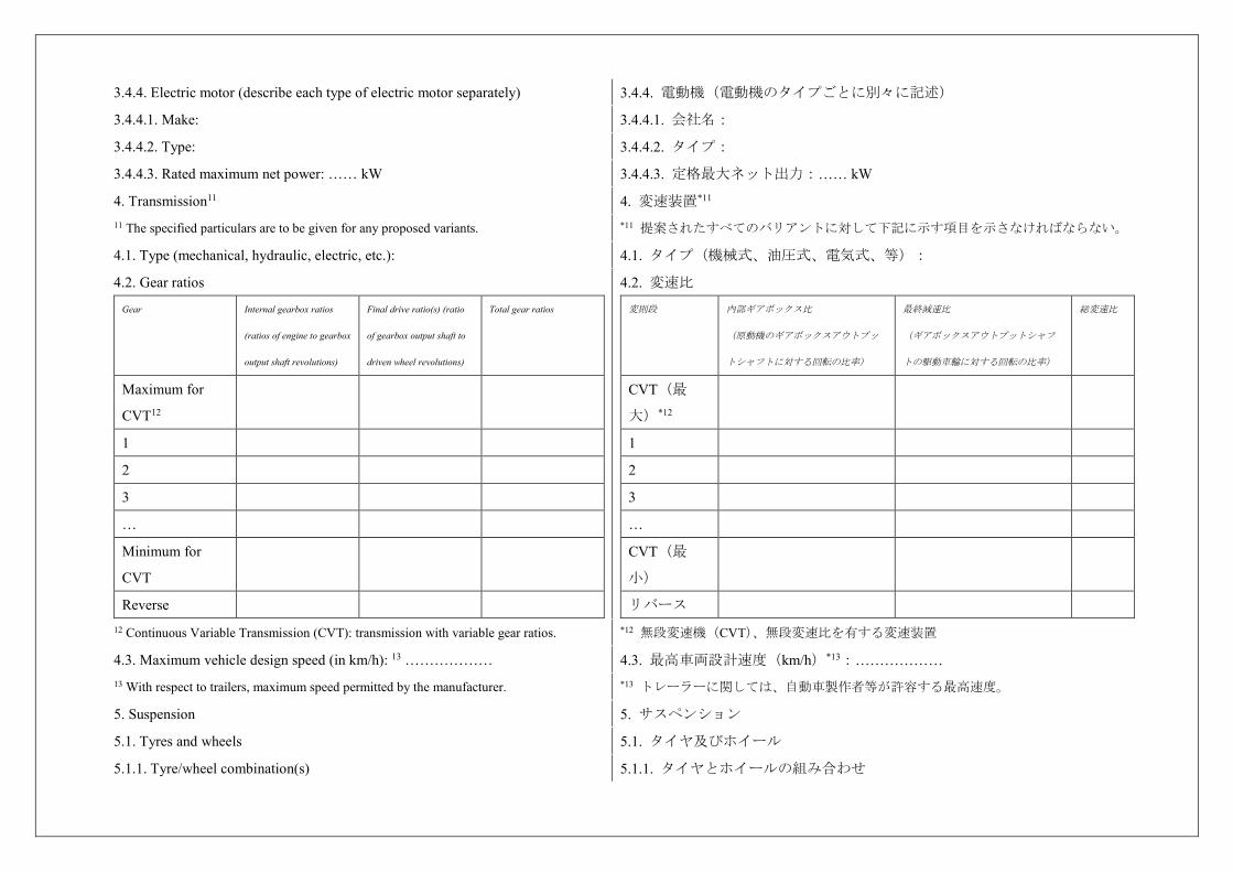
3.4.4. Electric motor (describe each type of electric motor separately) 3.4.4. 電動機(電動機のタイプごとに別々に記述)
3.4.4.1. Make: 3.4.4.1. 会社名:
3.4.4.2. Type: 3.4.4.2. タイプ:
3.4.4.3. Rated maximum net power: …… kW 3.4.4.3. 定格最大ネット出力:…… kW
4. Transmission11 4. 変速装置*11
11 The specified particulars are to be given for any proposed variants. *11 提案されたすべてのバリアントに対して下記に示す項目を示さなければならない。
4.1. Type (mechanical, hydraulic, electric, etc.): 4.1. タイプ(機械式、油圧式、電気式、等):
4.2. Gear ratios
Gear Internal gearbox ratios
(ratios of engine to gearbox
output shaft revolutions)
Final drive ratio(s) (ratio
of gearbox output shaft to
driven wheel revolutions)
Total gear ratios
Maximum for
CVT12
1
2
3
…
Minimum for
CVT
Reverse
4.2. 変速比
変則段 内部ギアボックス比
(原動機のギアボックスアウトプッ
トシャフトに対する回転の比率)
最終減速比
(ギアボックスアウトプットシャフ
トの駆動車輪に対する回転の比率)
総変速比
CVT(最
大)*12
1
2
3
…
CVT(最
小)
リバース
12 Continuous Variable Transmission (CVT): transmission with variable gear ratios. *12 無段変速機(CVT)、無段変速比を有する変速装置
4.3. Maximum vehicle design speed (in km/h): 13 ……………… 4.3. 最高車両設計速度(km/h)*13:……………… 13 With respect to trailers, maximum speed permitted by the manufacturer. *13 トレーラーに関しては、自動車製作者等が許容する最高速度。
5. Suspension 5. サスペンション
5.1. Tyres and wheels 5.1. タイヤ及びホイール
5.1.1. Tyre/wheel combination(s) 5.1.1. タイヤとホイールの組み合わせ
(a) For tyres indicate size designation, load-capacity index and speed category
symbol;
(a) タイヤについては、サイズ、ロードインデックス及び速度区分記号を記載す
る、
(b) For wheels indicate rim size(s) and off-set(s). (b) ホイールについては、リムサイズ及びオフセットを記載する
5.1.2. Upper and lower limits of rolling radii 5.1.2. 回転半径の上限値及び下限値
5.1.2.1. Axle 1: 5.1.2.1. アクスル1:
5.1.2.2. Axle 2: 5.1.2.2. アクスル2:
5.1.2.3. Axle 3: 5.1.2.3. アクスル3:
5.1.2.4. Axle 4: 5.1.2.4. アクスル4:
etc. 等
6. Bodywork 6. 車体
6.1. Type of bodywork: 6.1. 車体のタイプ:
6.2. Materials used and methods of construction: 6.2. 使用した材料及び組立方法:
7. Miscellaneous 7. 雑則
7.1. Details of any non-engine devices designed to reduce noise (if not covered by
other items):
7.1. 騒音低減用に設計された原動機によらない装置の詳細(他の項目で取り扱
われていない場合):
Signed: 署名:
Position in company: 会社での役職:
Date: 日付:
Annex 2 Arrangements of approval mark 附則 2 認可マークの配置
Model A
(See paragraph 5.4. of this Regulation)
The above approval mark affixed to a vehicle shows that the vehicle type
concerned has, with regard to its noise emission, been approved in the Netherlands
(E 4) pursuant to Regulation No. 51 under approval No. 032439.
The first two digits of the approval number indicate that Regulation No. 51 already
included the 03 series of amendments when the approval was granted.
様式 A
(本規則 5.4.参照)
車両に貼付される上記の認可マークは、当該車両型式が、騒音発生に関する協
定規則第51号に基づき、オランダ(E4)において認可番号032439で認可された
ことを表している。
認可番号の最初の2桁は、認可が付与された時に協定規則第51号には第3改定版
が既に盛り込まれていたことを表している。
Model B
(See paragraph 5.5. of this Regulation)
The above approval mark affixed to a vehicle shows that the vehicle type
concerned has been approved in the Netherlands (E 4) pursuant to Regulations
Nos. 51 and 33.1 The approval numbers indicate that, at the dates when the
respective approvals were granted, Regulation No. 51 included the 03 series of
amendments while Regulation No. 33 was in its original form.
様式 B
(本規則 5.5.参照)
車両に貼付された上記の認可マークは、当該車両型式が、協定規則第 51 号及
び協定規則第 33 号*1に基づいて、オランダ(E4)で認可されたことを表して
いる。各認可番号は、それぞれの協定規則による認可が付与された日付におい
て、協定規則第 51 号には第 3 改訂版が盛り込まれているが、協定規則第 33 号
は初版であることを表している。
4 51R-03 2439 a = 8 mm min
a = 8 mm min
4 51R-03 2439 a = 8 mm min
a = 最小 8 mm
1 The latter number is given as an example only. 1 後者の番号は単に例として挙げたものである。
Annex 3 Methods and instruments for measuring the sound made by motor
vehicles
附則 3 自動車より発生する騒音を測定するための方法及び計器
1. Measuring instruments 1. 測定装置
1.1. Acoustic measurements
The apparatus used for measuring the sound level shall be a precision sound-level
meter or equivalent measurement system meeting the requirements of class 1
instruments (inclusive of the recommended windscreen, if used). These
requirements are described in "IEC 61672-1:2002: Precision sound level meters",
second edition, of the International Electrotechnical Commission (IEC).
Measurements shall be carried out using the "fast" response of the acoustic
measurement instrument and the "A" weighting curve also described in "IEC
61672-1:2002". When using a system that includes a periodic monitoring of the A-
weighted sound pressure level, a reading should be made at a time interval not
greater than 30 ms.
The instruments shall be maintained and calibrated in accordance to the
instructions of the instrument manufacturer.
1.1. 音響測定
騒音の大きさを測定するために使用する装置は、クラス1計器の要件を満たす
(推奨されるウインドスクリーンを使用する場合はこれを含む)精密騒音計又
は同等の測定システムでなければならない。上記の要件は、国際電気標準会議
(IEC)の「IEC 61672-1:2002:精密騒音計」第2版に記述されている。
測定は、音響測定計器の「速い動特性」と「IEC 61672-1:2002」にも記述され
ている「A」加重曲線を用いて実施するものとする。A特性音圧レベルの定期
的なモニタリングを行うシステムを用いる場合、30 ms以下の時間間隔で読み
値を得るべきものとする。
計器は、計器メーカーの指示に従って保守及びキャリブレーションを行うもの
とする。
1.2. Calibration of the entire Acoustic Measurement System for a Measurement
Session
At the beginning and at the end of every measurement session the entire
measurement system shall be checked by means of a sound calibrator that fulfils
the requirements for sound calibrators of at least precision Class 1 according to
IEC 60942:2003. Without any further adjustment the difference between the
readings of two consecutive checks shall be less than or equal to 0.5 dB.
If this value is exceeded, the results of the measurements obtained after the
previous satisfactory check shall be discarded.
1.2. 測定に用いる音響測定システム全体のキャリブレーション
各測定の開始時及び終了時に、IEC 60942:2003に基づき少なくとも精度クラス1
の音量校正器の要件を満たす音量校正器を使って、全測定システムをチェック
するものとする。調整することなしに、2回連続したチェックの読み値の差異
が0.5 dB以下になるものとする。
この値を上回る差異があった場合、前回のチェックに合格した後に得られた測
定結果は全て無効とする。
1.3. Compliance with requirements 1.3. 要件への適合
Compliance of the acoustic measurement instrumentation shall be verified by the
existence of a valid certificate of compliance. These certificates shall be deemed to
be valid if certification of compliance with the standards was conducted within the
previous 12 month period for the sound calibration device and within the previous
24 month period for the instrumentation system. All compliance testing shall be
conducted by a laboratory, which is authorized to perform calibrations traceable to
the appropriate standards.
音響測定計器の適合性は、有効な適合証明書があるかどうかにより検証するも
のとする。音量校正器の場合は基準に適合することの検定が過去12ヶ月以内に
実施されており、計測システムの場合は過去24ヶ月以内に実施されていれば、
適合証が有効であるとみなす。すべての適合性のテストは、該当する基準に則
したキャリブレーションを実施することを承認された試験機関が実施しなけれ
ばならない。
1.4. Instrumentation for speed measurements
The engine speed shall be measured with instrumentation having an accuracy of ±2
per cent or better at the engine speeds required for the measurements being
performed.
The road speed of the vehicle shall be measured with instrumentation having an
accuracy of at least ±0.5 km/h, when using continuous measurement devices.
If testing uses independent measurements of speed, this instrumentation shall meet
specification limits of at least ±0.2 km/h.
1.4. 速度測定のための計器
エンジン回転数は、実施する測定で要求されるエンジン回転数において ±
2 %以内の精度を持つ計器で測定するものとする。
車両の路上速度は、連続測定装置(例 GPS、レーダー)を使用する場合、少
なくとも± 0.5 km/hの精度を有する計器で測定するものとする。
試験において速度の独立測定(例 光電管測定)を行う場合、この計器は少な
くとも± 0.2 km/hの精度を有すること。
1.5. Meteorological instrumentation
The meteorological instrumentation used to monitor the environmental conditions
during the test shall include the following devices, which meet at least the given
accuracy:
1.5. 気象測定装置
試験中の環境条件を監視するために使用する測定装置は、以下記載の装置を含
むこと。なお、これらの装置は少なくとも以下の精度を有すること。
(a) Temperature measuring device, ±1 °C; (a) 温度測定装置、± 1℃、
(b) Wind speed-measuring device, ±1.0 m/s; (b) 風速測定装置、± 1.0m/s、
(c) Barometric pressure measuring device, ±5 hPa; (c) 気圧測定装置、± 5hPa、
(d) A relative humidity measuring device, ±5 per cent. (d) 相対湿度測定装置、± 5%
2. Conditions of measurement 2. 測定条件
2.1. Test Site and ambient conditions
The surface of the test track and the dimensions of the test site shall be in
2.1. 試験場及び周囲条件
試験路の表面及び試験場の寸法は、ISO 10844:2014に従うものとする。
accordance with ISO 10844:2014.
The surface of the site shall be free of powdery snow, tall grass, loose soil or
cinders. There shall be no obstacle which could affect the sound field within the
vicinity of the microphone and the sound source. The observer carrying out the
measurements shall so position themself as not to affect the readings of the
measuring instrument.
Measurements shall not be made under adverse weather conditions. It shall be
ensured that the results are not affected by gusts of wind.
The meteorological instrumentation should be positioned adjacent to the test area at
a height of 1.2 m ±0.02 m. The measurements shall be made when the ambient air
temperature is within the range from 5 °C to 40 °C.
The tests shall not be carried out if the wind speed, including gusts, at microphone
height exceeds 5 m/s, during the sound measurement interval.
A value representative of temperature, wind speed and direction, relative humidity,
and barometric pressure shall be recorded during the sound measurement interval.
Any sound peak which appears to be unrelated to the characteristics of the general
sound level of the vehicle shall be ignored in taking the readings.
The background noise shall be measured for duration of 10 seconds immediately
before and after a series of vehicle tests. The measurements shall be made with the
same microphones and microphone locations used during the test. The A-weighted
maximum sound pressure level shall be reported.
The background noise (including any wind noise) shall be at least 10 dB below the
A-weighted sound pressure level produced by the vehicle under test. If the
difference between the ambient noise and the measured sound is between 10 and
15 dB(A), in order to calculate the test results the appropriate correction shall be
subtracted from the readings on the sound-level meter, as in the following table:
試験場の表面には、粉雪、背の高い草、軟土や灰がないものとする。マイクロ
ホンと音源の付近で音場に影響を与え得る障害物があってはならない。測定を
行う観察者は、測定計器の読み値に影響を与えることのない位置にいなければ
ならない。
測定は天候条件が悪いときに行わないものとする。試験結果は突風による影響
を受けていないことが確認されなければならない。
気象測定装置は、試験場の近くで高さ1.2 ± 0.02 mに配置すること。測定は、周
囲の気温が5℃から40 ℃の範囲内にあるときに実施するものとする。
試験は、マイクロホンの高さにおける風速(突風を含む)が音量測定中に5 m/s
を超えるときは実施しないものとする。
音量測定中、温度、風速及び風向、相対湿度、気圧の代表値を記録するものと
する。
読み値の記録に当たり、車両の一般的な騒音の大きさの特性に関係がないと考
えられる騒音ピークは除外すること。
暗騒音は、一連の車両試験の直前及び直後の10秒間にわたって測定するものと
する。この測定は、試験中と同じマイクロホン及びマイクロホン位置を用いて
実施するものとする。最大A特性音圧レベルを報告するものとする。
暗騒音(ウインドノイズを含む)は、試験対象車両が発するA特性音圧レベル
よりもA特性で少なくとも10 dB低いこと。暗騒音と実測音との差が10から15
dB(A)の範囲の場合、試験結果を計算するために以下の表に記す通り、騒音
計の読み値より適当な補正値を引かなければならない。
Difference between ambient noise and
sound to be measured dB(A)
10 11 12 13 14 15
Correction dB(A) 0.5 0.4 0.3 0.2 0.1 0.0
暗騒音と実測音の差 dB(A)
10 11 12 13 14 15
補正値 dB(A) 0.5 0.4 0.3 0.2 0.1 0.0
2.2. Vehicle 2.2. 車両
2.2.1. The vehicle shall be representative of vehicles to be put on the market as
specified by the manufacturer in agreement with the Technical Service to fulfil the
requirements of this Regulation.
Measurements shall be made without any trailer, except in the case of non-
separable vehicles. At the request of the manufacturer, measurements may be made
on vehicles with lift axle(s) in a raised position.
Measurements shall be made on vehicles at the test mass mt specified according to
the following table.
Target mass, mtarget, is used to denote the mass that N2 and N3 vehicles should be
tested at. The actual test mass of the vehicle can be less due to limitations on
vehicle and axle loading.
Vehicle category Vehicle test mass
M1 mt = mro +/- 5%
N1 mt = mro +/- 5%
N2, N3 mtarget = 50 [kg/kW] x Pn [kW]
Extra loading, mxload, to reach the target mass, mtarget, of the
vehicle shall be placed above the rear axle(s).
The sum of the extra loading and the rear axle load in an
unladen condition, mra load unladen, is limited to 75 per cent of the
technically permissible maximum laden mass allowed for the
rear axle, mac ra max. The target mass shall be achieved with a
tolerance of ±5 per cent.
2.2.1. 車両は、本規則の要件を満たすために技術機関との合意に基づき自動車
製作者等が定める、市販される車両を代表するものとする。
分離不可能な車両の場合を除き、測定はトレーラーなしで実施するものとす
る。自動車製作者等の要求に応じ、リフトアクスルを有する車両において上昇
位置で測定を実施してもよい。
車両の測定は、以下の表に従って指定された試験質量mtで行うものとする:
試験時に測定されるべきN2及びN3車両の質量を目標車両質量mtargetで表す。車
両及びアクスル負荷の限界により、車両の実際の試験時質量はこれを下回るこ
とがありえる。
車両カテゴリー 自動車の試験時質量
M1 mt = mro ± 5%
N1 mt = mro ± 5%
N2, N3 mtarget = 50 [kg/kW] x Pn [kW]
車両の試験時質量に達する追加荷重、mxloadは後軸上に
置くこと。
追加荷重と非積載状態の後軸軸重の合計は、後軸の許
容最大質量、mac ra maxの75 %に制限される。目標車両質
量は± 5 %の公差内で達成されること。
If the centre of gravity of the extra loading cannot be aligned
with the centre of the rear axle, the test mass, mt, of the vehicle
shall not exceed the sum of the front axle in an unladen
condition, mfa load unladen, and the rear axle load in an unladen
condition, mra load unladen plus the extra loading, mxload, and the
mass of the driver md.
The test mass for vehicles with more than two axles shall be the
same as for a two-axle vehicle.
If the vehicle mass of a vehicle with more than two axles in an
unladen condition, munladen, is greater than the test mass for the
two-axle vehicle, then this vehicle shall be tested without extra
loading.
If the vehicle mass of a vehicle with two axles, munladen, is
greater than the target mass, then this vehicle shall be tested
without extra loading.
M2, M3 mt = mro
The mass in running order shall be achieved with a tolerance of
±10%.
Incomplete
M2, M3
If the tests are carried with an incomplete vehicle not having a
bodywork,
mtarget = 50 [kg/kW] x Pn [kW] is calculated in compliance with
conditions above (see N2, N3 category),
or
mt = mchassisM2M3 + mxloadM2M3 = mro
The mass in running order shall be achieved with a tolerance of
±10%.
追加荷重の重心が後軸の中心と位置合わせができない
場合、自動車の試験時質量mtは、非積載状態の前軸軸
重、 mfa load unladen、非積載状態の後軸軸重mra load unladen、
追加荷重mxload及び運転者の質量mdの合計を超えないこ
と。
2軸を超える自動車における試験時質量は、2軸の自動
車の場合と同じとすること。
非積載状態の2軸を超える自動車の質量munladenが2軸の自
動車の試験時質量より大きい場合、この自動車は追加
荷重無しで試験する。
2軸の自動車の質量munladenが目標車両質量より大きい場
合、この自動車は追加荷重無しで試験する。
M2, M3 mt = mro
ランニングオーダー質量は± 10%の公差内とする。
未完成車
M2, M3
車体架装が無い未完成車の試験を実施する場合、
mtarget = 50 [kg/kW] x Pn [kW] は上記条件に基づいて計算
する(N2, N3 カテゴリ参照),
又は、
mt = mchassisM2M3 + mxloadM2M3 = mro
ランニングオーダー質量は± 10%の公差内とする。
2.2.2. At the applicant's request the vehicle of a category M2, M3, N2 or N3 is
deemed representative of its completed type if the tests are carried out to an
incomplete vehicle not having a bodywork. In the test of an incomplete vehicle all
relevant soundproofing materials, panels and noise reduction components and
systems shall be fitted on the vehicle as designed by the manufacturer except a part
of bodywork which is built in a later stage.
No new test shall be required due to fitting of a supplement fuel tank or re-location
of the original fuel tank on condition that other parts or structures of the vehicle
apparently affecting sound emissions have not been altered.
The tyres to be used for the test shall be representative for the vehicle and shall be
selected by the vehicle manufacturer and recorded in Addendum to the
Communication form (Annex 1, Appendix 1). They shall correspond to one of the
tyre sizes designated for the vehicle as original equipment. The tyre is or will be
commercially available on the market at the same time as the vehicle. 1 The tyres
shall be inflated to the pressure recommended by the vehicle manufacturer for the
test mass of the vehicle. The tyres shall have at least 1.6 mm tread depth.
2.2.2. 車体を装備していない未完成車両で試験が実施される場合、申請者の要
求に応じ、カテゴリーM2、M3、N2又はN3の車両は、その完成車両の型式を代
表するものとみなされる。未完成車両の試験においては、後工程で装着される
車体の部品を除いて、自動車製作者等の設計通りにすべての関連防音材、パネ
ル及び騒音低減部品が装着されること。
騒音に影響を及ぼしている車両の他の部品又は構造が変更されていないという
条件において、補助燃料タンクの取り付けや標準の燃料タンクの再配置に起因
して新たに試験が要求されないものとする。
試験に使用するタイヤは、当該車両の代表的なものとし、自動車製作者等が選
択し、通知書の補足(附則1補足)に記録されるものとする。それらは、標準
装備品として当該車両に指定されたタイヤサイズのいずれかに対応するものと
する。当該タイヤは、現在又は今後、当該車両と同時期に市販されるものであ
る。*1これらのタイヤは、当該車両の試験時質量に対して自動車製作者等が推
奨する空気圧に設定する。タイヤのトレッドの深さは1.6 mm以上のこと。
1 Given that the tyre contribution for overall sound emission is significant, regard shall be
given for existing regulatory provisions concerning tyre/road sound emissions. Traction
tyres, snow tyres and special-use tyres as defined in paragraph 2. of Regulation No 117 shall
be excluded during type-approval and conformity of production measurements at the request
of the manufacturer in accordance with Regulation No. 117.
*1 全体的な騒音放射にタイヤによる寄与が重要であるため、タイヤ/道路の騒音放射
に関する既存の規定条項を考慮しなければならない。協定規則第117号の2項に定義され
るトラクションタイヤ、スノータイヤ及び特殊タイヤは、協定規則第117号に基づく製
作者等の要請があれば、型式認可及び生産の適合性における測定において除外されるも
のとする。
2.2.3. Before the measurements are started, the engine shall be brought to its
normal operating conditions.
2.2.3. 測定を開始する前に、原動機は通常の運転する状態になっているものと
する。
2.2.4. If the vehicle is fitted with more than two-wheel drive, it shall be tested in
the drive which is intended for normal road use.
2.2.4. 駆動輪が2輪を超える車両の場合、一般道路使用を意図した駆動条件で
試験するものとする。
2.2.5. If the vehicle is fitted with fan(s) having an automatic actuating mechanism, 2.2.5. 車両に自動作動機構の付いたファンが装備されている場合は、測定中に
this system shall not be interfered with during the measurements. このシステムの作動を妨げてはならない。
2.2.6. If the vehicle is equipped with an exhaust system containing fibrous
materials, the exhaust system is to be conditioned before the test according to
Annex 4.
2.2.6. 繊維性材料が含まれている排気システムを車両が装備している場合は、排
気システムは試験前に附則4に従って試験準備を行うこと。
2.2.7. Calculation procedure to determine extra loading of N2 and N3 vehicles only 2.2.7. N2及びN3車両のみの追加荷重を決定するための計算手順
2.2.7.1. Calculation of extra loading
The target mass, mtarget, (per kW rated power) for two-axle vehicles of category N2
and N3 is specified in Table 2.2.1:
mtarget = 50 [kg / kW] × Pn [kW] (1)
To reach the required target mass, mtarget, for a vehicle being tested, the unladen
vehicle, including the mass of the driver, md, shall be loaded with an extra mass,
mxload, which shall be placed above the rear axle as given in Formula (8):
mtarget = munladen + md + mxload (2)
The target mass, mtarget, shall be achieved with a tolerance of ±5 per cent.
The vehicle mass of the test vehicle in the unladen condition, munladen, is calculated
by measuring on a scale the unladen front axle load, mfa load unladen, and the unladen
rear axle load, mra load unladen, as given in Formula (3):
munladen = mfa load unladen + mra load unladen (3)
By using Formulae (2) and (3), the extra loading, mxload, is calculated as given in
Formulae (4) and (5):
mxload = mtarget – (md + munladen) (4)
mxload = mtarget − (md + mfa load unladen + mra load unladen) (5)
The sum of the extra loading, mxload, and the unladen rear axle load, mra load unladen, is
limited to 75 per cent of the technically permissible maximum laden mass for the
rear axle, mac ra max, as given in Formula (6):
0,75 mac ra max ≥ mxload + mra load unladen (6)
2.2.7.1. 追加荷重の計算
カテゴリーN2及びN3の2軸車両に関する目標車両質量mtarget(定格エンジン出力
1kWあたり)は、表 2.1.1に規定される。
mtarget = 50 [kg / kW] × Pn [kW] (1)
試験対象車両を要求される目標車両質量mtargetに到達させるため、式(8)に示す
ように、運転者の質量(md)を含む非積載車両に対し、後軸の上方に追加質量
mxloadを載せるものとする。
mtarget = munladen + md + mxload (2)
目標車両質量mtargetは ± 5 %の公差で達成するものとする。
非積載状態における試験車両の車両質量munladenは、式(3)に示すように、非積載
状態の前軸軸重mfa load unladen及び非積載状態の後軸軸重mra load unladenを測定するこ
とによって計算される。
munladen = mfa load unladen + mra load unladen (3)
式(2)及び(3)により、式(4)及び(5)に示すように追加加重mxloadが計算される。
mxload = mtarget – (md + munladen) (4)
mxload = mtarget − (md + mfa load unladen + mra load unladen) (5)
追加負荷mxloadと非積載状態の後軸軸重mra load unladenの合計は、式(6)に示すよう
に、後軸に関する技術的最大許容質量 mac ra maxの75 %までに制限する
0.75 mac ra max ≥ mxload + mra load unladen (6)
The mxload is limited according to Formula (7):
mxload ≤ 0,75 mac ra max − mra load unladen (7)
If the calculated extra loading, mxload, in Formula (5) fulfils Formula (7), then the
extra loading is equal to Formula (5). The test mass, mt, of the vehicle is as
calculated from Formula (8):
mt = mxload + md + mfa load unladen + mra load unladen (8)
In this case, the test mass of the vehicle is equal to the target mass
mt = mtarget (9)
If the calculated extra loading, mxload, in Formula (5) does not fulfil Formula (7),
but rather fulfils Formula (10)
mxload > 0,75 mac ra max − mra load unladen (10)
then, the extra loading, mxload, shall be as given by Formula (11):
mxload = 0,75 mac ra max − mra load unladen (11)
and the test mass, mt, of the vehicle shall be as given by Formula (12):
mt = 0,75 mac ra max + md + mfa load unladen (12)
In this case, the test mass of the vehicle is lower than the target mass
mt < mtarget (13)
mxloadは、式(7)によって制限される。
mxload ≤ 0.75 mac ra max − mra load unladen (7)
式(5)で計算した追加荷重mxloadが式(7)を満たすとき、追加荷重は式(5)に等し
い。車両の試験質量(mt)は、式(8)から計算される値である。
mt = mxload + md + mfa load unladen + mra load unladen (8)
この場合,車両の試験時質量は目標車両質量に等しい。
mt = mtarget (9)
式(5)で計算した追加荷重mxloadが式(7)ではなく式(10)を満たすとき、
mxload > 0.75 mac ra max − mra load unladen (10)
追加荷重mxloadは式(11)によって与えられる。
mxload = 0.75 mac ra max − mra load unladen (11)
また,その車両の試験質量(mt)は式(12)によって与えられる。
mt = 0.75 mac ra max + md + mfa load unladen (12)
この場合、車両の試験質量は目標車両質量より小さくなる。
mt < mtarget (13)
2.2.7.2. Loading considerations if load cannot be aligned with the centre of rear
axle
If the centre of gravity of the extra loading, mxload, cannot be aligned with the
centre of the rear axle, the test mass of the vehicle, mt, shall not exceed the sum of
the unladen front axle load, mfa load unladen, and the unladen rear axle load, mra load
unladen, plus the extra loading, mxload, and the mass of the driver, md.
This means that if the actual front and rear axle loads are measured on a scale when
the extra loading, mxload, is placed onto the vehicle and it is aligned with the centre
of the rear axle, the test mass of the vehicle minus the mass of the driver is as given
by Formula (14):
2.2.7.2. 荷重が後軸の中心に一致できない場合の荷重条件
追加荷重の重心mxloadを後軸の中心に一致できない場合でも、車両の試験時質量
mtは、非積載状態の前軸荷重mfa load unladenと非積載状態の後軸荷重mra load unladenの
合計に追加荷重mxloadと運転者の質量mdを加えた値を超えないこと。
これは追加荷重mxloadを車両に載せて後軸の中心に一致させた状態で実際の前軸
及び後軸軸重を測定した場合、車両の試験時質量から運転者の質量を引く計算
が式(14)で与えられることを意味する。
mt − md = mfa load laden + mra load laden (14)
where
mfa load laden = mfa load unladen (15)
If the centre of gravity of the extra loading cannot be aligned with the centre of the
rear axle, Formula (14) is still fulfilled, but
mfa load laden > mfa load unladen (16)
because the extra loading has partly distributed its mass to the front axle. In that
case, it is not allowed to add more mass onto the rear axle to compensate for the
mass moved to the front axle.
mt − md = mfa load laden + mra load laden (14)
ここで、
mfa load laden = mfa load unladen (15)
追加荷重の重心が後軸の中心に一致しない場合でも、式(14)は満たされるが、
mfa load laden > mfa load unladen (16)
になる。これは、追加荷重がその質量を前軸に部分的に分散させるためであ
る。その場合、前軸に移動した質量を補うために後軸に質量を追加しない。
2.2.7.3. Test mass for vehicles with more than two axles
If a vehicle with more than two axles is tested, then the test mass of this vehicle
shall be the same as the test mass for the two-axle vehicle.
If the unladen vehicle mass of a vehicle with more than two axles is greater than
the test mass for the two-axle vehicle, then this vehicle shall be tested without extra
loading.
2.2.7.3. 車軸数が2より多い車両の試験質量
車軸数が2より多い車両を試験する場合、その車両の試験質量は、2車軸車両の
試験質量と同一であるものとする。
車軸数が2より多い車両の非積載車両質量が2車軸車両の試験質量を上回る場合
は、その車両を追加荷重なしで試験するものとする。
3. Methods of testing 3. 試験方法
3.1. Measurement of sound of vehicles in motion 3.1. 走行中の車両騒音の測定
3.1.1. General conditions of test
Two lines, AA' and BB', parallel to line PP' and situated respectively 10 m ± 0.05
m forward and 10 m ± 0.05 m rearward of line PP' shall be marked out on the test
runway.
At least four measurements shall be made on each side of the vehicle and for each
gear. Preliminary measurements may be made for adjustment purposes, but shall be
disregarded.
The microphone shall be located at a distance of 7.5 m ± 0.05 m from the reference
line CC' of the track and 1.2 m ± 0.02 m above the ground.
3.1.1. 試験の一般条件
PP'に平行かつPP'よりそれぞれ10 m ± 0.05 m前方と10 m ± 0.05 m後方に位置する
AA'とBB'の2つのラインを試験路上にわかるようにする。
車両の各側及び各変速段で少なくとも4回の測定を実施する。調整のために予
備測定を実施してもよいが、結果は無視する。
マイクロホンは、試験路上の基準ラインCC'より7.5 m ± 0.05 mの距離を隔て
て、地面から1.2 m ± 0.02 mの高さに配置する。
The reference axis for free field conditions (see IEC 61672-1:2002) shall be
horizontal and directed perpendicularly towards the path of the vehicle line CC'.
自由音場条件(IEC 61672-1:2002参照)でのマイクロホンの向きは、水平かつ車両
走行ラインCC'に垂直とする。
3.1.2. Specific test conditions for vehicles 3.1.2. 試験条件
3.1.2.1. Vehicles of category M1, M2 ≤ 3,500 kg technically permissible maximum
laden mass, N1
The path of the centreline of the vehicle shall follow line CC' as closely as possible
throughout the entire test, from the approach to line AA' until the rear of the
vehicle passes line BB'. If the vehicle is fitted with more than two-wheel drive, test
it in the drive selection which is intended for normal road use.
If the vehicle is fitted with an auxiliary manual transmission or a multi-gear axle,
the position used for normal urban driving shall be used. In all cases, the gear ratios
for slow movements, parking or braking shall be excluded.
The test mass of the vehicle shall be according to the table of paragraph 2.2.1.
The test speed vtest is 50 km/h ± 1 km/h. The test speed shall be reached, when the
reference point is at line PP'.
If the test speed is modified according to paragraph 3.1.2.1.4.1.(e) of Annex 3 to
this Regulation, the modified test speed shall be used for both the acceleration and
constant speed test.
3.1.2.1. カテゴリーM1、M2 ≦ 3,500 kg(技術的最大許容質量)及びN1の車両
車両の中心線は、AA'に進入してから車両の後端がBB'を通過するまで、全試験
区間中、可能な限りCC'上を走行するものとする。二輪駆動を超える車両の場
合、一般道路使用を意図した駆動条件で試験する。
車両に補助手動変速機、又はマルチギアアクスルが装備されている場合、通常
の市街地走行に用いられる位置を使用するものとする。すべての場合で、低速
走行、駐車又は制動用の変速比は除外するものとする。
車両の試験時質量は本附則2.2.1.の表に従うものとする。
試験速度vtestは、50 km/h±1 km/hである。試験速度は、基準点がPP'にあるとき
に到達しなければならない。
本附則3の3.1.2.1.4.1.(e)に従って試験速度を変更した場合、その変更した試
験速度を加速試験と定速走行試験の両方に使用するものとする。
3.1.2.1.1. Power to mass ratio index (PMR)
PMR is defined as follows:
PMR = (Pn / mro) * 1000 kg/kW, where Pn is measured in kW and mro is measured
in kg according to paragraph 2.2.1. of this Annex.
If two or more sources of propulsive power operate at the conditions of test
specified in paragraph 3.1.2.1 of Annex 3 to this Regulation, the total engine net
power, Pn, shall be the arithmetic sum of parallel propulsive engines on the vehicle.
Applicable parallel propulsive engines are those power sources which provide
3.1.2.1.1. パワーマスレシオ(PMR)
PMRは以下で定義する。
PMR = (Pn / mro) × 1,000
ここで、PnはkW単位で測定され、mroはkg単位で測定される。
附則3の3.1.2.1.に規定された試験条件において複数の推進力源が動作する場
合、総エンジン出力Pnは、当該車両の並列推進エンジンの算術的合計とする。
これに該当する並列推進エンジンは、附則3の3.1.2.1.に規定された試験条件に
おいて複数の組み合わせで車両に前進運動を与える出力源である。非内燃機関
forward motion to the vehicle in combination at the conditions of test specified in
paragraph 3.1.2.1. of Annex 3 to this Regulation. Specified power for non-
combustion engines shall be the power stated by the manufacturer.
The PMR with no dimension is used for the calculation of acceleration.
の出力は、自動車製作者等の仕様値とする。
パワーマスレシオ(PMR)は、無次元で加速度計算に使用する。
3.1.2.1.2. Calculation of acceleration
Acceleration calculations are applicable to M1, N1 and M2 ≤ 3,500 kg technically
permissible maximum laden mass categories only.
All accelerations are calculated using different speeds of the vehicle on the test
track. 2 The formulae given are used for the calculation of awot i, awot i+1 and awot test.
The speed either at AA' or PP' is defined as the vehicle speed when the reference
point passes AA' (vAA') or PP' (vPP'). The speed at BB' is defined when the rear of
the vehicle passes BB' (vBB'). The method used for determination of the
acceleration shall be indicated in the test report.
Due to the definition of the reference point for the vehicle the length of the vehicle
(lveh) is considered differently in the formula below. If the reference point is in the
front of the vehicle, then l = lveh, mid: l = ½ lveh and rear: l = 0.
At the choice of the vehicle manufacturer, front engine vehicles may use l = 5 m,
and mid-engine vehicles may use l = 2.5 m.
3.1.2.1.2. 加速度計算
加速度計算は、カテゴリーM1、N1及びM2 ≦ 3,500 kg(技術的最大許容質量)
のみに適用する。
すべての加速度は、試験路上での車両速度差によって計算する*2。後述する式
をawot i、awot i+1及びawot testの計算に使用する。AA'またPP'のいずれかにおける車
両速度は、基準点がAA'又はPP'を通過するときの車両速度(vAA'又はvPP')とし
て定義される。BB'における車両速度(vBB')は、車両の後端がBB'を通過する
ときの車両速度として定義される。加速度の決定に使用した方法は、試験成績
書に記入するものとする。
車両の基準点の定義から、以下の式で用いるlは、フロントエンジン車の場合
はl = lveh、ミッドエンジン車の場合はl = ½ lveh、リヤエンジン車の場合はl = 0と
する。
自動車製作者等の選択により、フロントエンジン車にはl =5 m 、ミッドエンジ
ン車はl =2.5 m を使用することができる。 2 See Annex 3, Appendix, Figure 1. *2 附則3付録の図1参照
3.1.2.1.2.1. Calculation procedure for vehicles with manual transmission,
automatic transmission, adaptive transmissions and transmissions with continuous
variable transmissions (CVT's) tested with locked gear ratios:
awot test = ((vBB'/3.6)2 - (vAA'/3.6)2) / (2*(20+l))
awot test used in the determination of gear selection shall be the average of the four
awot test, i during each valid measurement run.
Pre-acceleration may be used. The point of depressing the accelerator before line
3.1.2.1.2.1. 手動変速機、自動変速機、適応型変速機及び無段変速機(CVT)を
搭載した車両が変速比を固定して試験する場合の計算方法。
awot test = ((vBB'/3.6)2 - (vAA'/3.6)2) / (2*(20+l))
変速段選択を決定する際に使用するawot testは、有効な各回の測定走行中の4つの
awot test, iの平均値とする。
予備加速を使用してもよい。AA’よりも前で加速状態にした地点を、通知書の
AA' shall be reported in the Addendum to the Communication form (Annex 1,
Appendix 1).
補足(附則1 補足)で報告すること。
3.1.2.1.2.2. Calculation procedure for vehicles with automatic transmissions,
adaptive transmissions and CVT's tested with non-locked gear ratios:
awot test used in the determination of gear selection shall be the average of the four
awot test, i during each valid measurement run.
If devices or measures described in paragraph 3.1.2.1.4.2. can be used to control
transmission operation for the purpose of achieving test requirements, calculate awot
test using the equation:
awot test = ((vBB'/3.6)2 - (vAA'/3.6)2) / (2*(20+l))
Pre-acceleration may be used.
If devices or measures described in paragraph 3.1.2.1.4.2. are not used, calculate
awot test using the equation:
awot_testPP-BB = ((vBB'/3.6)2 - (vPP'/3.6)2) / (2*(10+l))
Pre-acceleration shall not be used.
The location of depressing the accelerator shall be where the reference point of the
vehicle passes line AA'.
3.1.2.1.2.2. 自動変速機、適応型変速機及び無段変速機(CVT)を搭載した車両
が変速比を固定しないで試験する場合の計算方法。
変速段選択を決定する際に使用するawot testは、有効な各回の測定走行中の4つの
awot test,iの平均値とする。
試験要件を満足する目的で、変速機を制御するために本附則3.1.2.1.4.2.に示す
装置や方法を使用する場合、下式を使用してawot testを求めること。
awot test = ((vBB'/3.6)2 - (vAA'/3.6)2) / (2*(20+l))
予備加速を使用してもよい。
本附則3.1.2.1.4.2.に示す装置や方法を使用しない場合、下式を使用してawot testを
計算すること。
awot_testPP-BB = ((vBB'/3.6)2 - (vPP'/3.6)2) / (2*(10+l))
予備加速を使用してはならない。
加速状態にする位置は、車両の基準点がAA'を通過する点とすること。
3.1.2.1.2.3. Target acceleration
The target acceleration aurban defines the typical acceleration in urban traffic and is
derived from statistical investigations. This function depends on the PMR of a
vehicle.
The target acceleration aurban is defined by:
aurban = 0.63 * log10 (PMR) - 0.09
3.1.2.1.2.3. 目標加速度
目標加速度aurbanは、統計的な調査によって求められた市街地交通における標準
的な加速度を定義するものである。目標加速度は車両のPMRに応じた関数とな
る。
目標加速度aurbanは以下の通り定義される。 aurban = 0.63 * log10 (PMR) - 0.09
3.1.2.1.2.4. Reference acceleration
The reference acceleration awot ref defines the required acceleration during the
acceleration test on the test track. It is a function depending on the power-to-mass
3.1.2.1.2.4. 参照加速度
参照加速度awot refは、試験路での加速試験の間に必要とされる加速度を定義す
る。それは車両のパワーマスレシオに依存する関数である。その関数は車両カ
ratio of a vehicle. That function is different for specific vehicle categories.
The reference acceleration awot ref is defined by:
awot ref = 1.59 * log10 (PMR) -1.41 for PMR ≥ 25
awot ref = a urban = 0.63 * log10 (PMR) - 0.09 for PMR < 25
テゴリーにより異なる。
参照加速度awot refは以下で定義される。
PMR ≧ 25の場合、awot ref = 1.59×log10 (PMR) -1.41
PMR < 25の場合、awot ref = a urban = 0.63×log10 (PMR) - 0.09
3.1.2.1.3. Partial power factor kP
The partial power factor kP (see paragraph 3.1.3.1.) is used for the weighted
combination of the test results of the acceleration test and the constant speed test
for vehicles of category M1 and N1 and M2 < 3,500 kg technically permissible
maximum laden mass
In cases other than a single gear test, awot ref shall be used instead of awot test (see
paragraph 3.1.3.1.).
3.1.2.1.3. 部分加速係数kp
部分加速係数kP(本附則3.1.3.1.参照)は、カテゴリーM1、N1及びM2 < 3,500 kg
(技術的最大許容質量)において、加速試験と定速試験の試験結果を加重して
計算するために使用する。
複数の変速段を用いた試験を行う場合、awot testに代わってawot ref を使う(本附
則3.1.3.1,参照)。
3.1.2.1.4. Gear ratio selection
The selection of gear ratios for the test depends on their specific acceleration
potential awot under full throttle condition, according to the reference acceleration
awot ref required for the full throttle acceleration test.
If the vehicle allows different transmission setups like automatic or manual gear
selection and/or has different software programs or modes (e.g. sporty, winter,
adaptive) leading to valid accelerations, the vehicle manufacturer shall prove to the
satisfaction of the Technical Service, that the vehicle is tested in the mode which
achieves an acceleration being closest to awot ref.
The vehicle transmission, gear, or gear ratio may be controlled by electronic or
mechanical measures to avoid the activation of a kick-down function.”
Appendix 3, Figure 3a to Figure 3e, give gear selection criteria and test run criteria
for categories M1 and M2 having a technically permissible maximum laden mass
not exceeding 3.500 kg and for category N1, in a flowchart form as an aid to test
operation.
3.1.2.1.4. 変速比の選択
全開加速試験で必要となる参照加速度awot ref に従い、試験での変速比の選択は
全開加速のもとでの加速性能awot によって決まる。
一部の車両では、異なる制御プログラムや変速機のモード(例 スポーツモー
ド、スノーモード、アダプティブ制御 等)を有する場合がある。車両が有効
な加速となる異なるモードを有する場合には、自動車製作者等は車両がawot ref
に最も近い加速度となるモードで試験されていることを技術機関に示す必要が
ある。
キックダウン機能の作動を回避するため、車両の変速装置、変速段又は変速比
を電子的又は機械的手段によって制御してもよい。
試験を実施するための参考として、附則3付録の図3aから図3eにカテゴリー
M1、技術的最大許容質量が3,500 kg以下のカテゴリーM2及びカテゴリーN1に関
する変速段選択基準及び試験実施基準をフローチャート形式で示す。
3.1.2.1.4.1. Vehicles with manual transmission, automatic transmissions, adaptive
transmissions or CVTs tested with locked gear ratios
The following conditions for selection of gear ratios are possible:
3.1.2.1.4.1. 変速比を固定して試験する手動変速機、自動変速機、適応型変速機
又は無段自動変速機を備える車両の場合。
変速段の選択は以下の条件となる。
(a) If one specific gear ratio gives an acceleration in a tolerance band of ±5 per cent
of the reference acceleration awot ref, not exceeding 2.0 m/s2, test with that gear ratio.
(a) ある特定の変速比で得られた加速度が、参照加速度awot ref の ± 5 %の許容
範囲内で、かつ2.0 m/s2を超えない場合は、その変速比で試験する。
(b) If none of the gear ratios give the required acceleration, then choose a gear ratio
i, with an acceleration higher and a gear ratio i+1, with anacceleration lower than
the reference acceleration. If the acceleration value in gear ratio i does not exceed
2.0 m/s2, use both gear ratios for the test. The weighting ratio in relation to the
reference acceleration awot ref is calculated by:
k = (awot ref – awot (i+1))/(awot (i) – awot (i+1))
(b) どの変速比においても必要な加速度が得られない場合は、参照加速度より
も高い加速度の変速比i及び参照加速度よりも低い加速度の変速比i+1を選択す
る。変速比iにおける加速度の値が2.0 m/s2を超えない場合は、両方の変速比を
試験に使用する。参照加速度awot ref に関する変速段重み付け係数kは、以下に
よって計算される。
k = (awot ref – awot (i+1))/(awot (i) – awot (i+1))
(c) If the acceleration value of gear ratio i exceeds 2.0 m/s2, the first gear ratio shall
be used that gives an acceleration below 2.0 m/s2 unless gear ratio i+1 provides
acceleration less than aurban. In this case, two gears, i and i+1 shall be used,
including the gear i with acceleration exceeding 2.0 m/s2. In other cases, no other
gear shall be used. The achieved acceleration awot test during the test shall be used
for the calculation of the part power factor kP instead of awot ref.
(c) 変速比iの加速度の値が2.0 m/s2を超える場合は、変速比i+1の加速度がaurban
を下回らない限り、2.0 m/s2以下の加速度を与える最初の変速比を使用するも
のとする。
変速比i+1の加速度がaurban に達しない場合は、変速比iの加速度2.0m/s2を超えて
も、変速比i及び変速比i+1の2個の変速比が使用される。
他の変速段は使用しないこととする。
(d) If the vehicle has a transmission in which there is only one selection for the
gear ratio the acceleration test is carried out in this vehicle gear selection. The
achieved acceleration is then used for the calculation of the part power factor kP
instead of awot ref.
(d) 車両の変速機に選択できる変速比が1つしかない場合、加速試験は、この変
速比を選択して実施される。部分加速係数kpの計算では、awot ref の代わりに得
られた加速度awot test を使用するものとする。
(e) If rated engine speed is exceeded in a gear ratio before the vehiclepasses BB'
the next higher gear shall be used. If the next higher gear results in an acceleration
below aurban, the vehicle test speed, vtest, shall be reduced by 2.5 km/h and the gear
ratio selection shall proceed as specified by the options given in this paragraph. In
no case shall the vehicle test speed be reduced below 40 km/h. In this case, a gear
(e) ある変速比において、車両がBB’を通過する前に定格エンジン回転数を超
える場合、次に高い変速比を使用する。次に高い変速比の加速度が目標加速度
aurban に達しない場合、試験車速vtest を2.5 km/hずつ低下させ、変速比の選定
は、この項の選択肢での指定に従って進める。いかなる場合も、試験車速は40
km/h未満には下げない。この場合、awot test はaurban を超えなくても、この変速
ratio is allowed even if awot test does not exceed aurban. 比を使用する。
3.1.2.1.4.2. Vehicles with automatic transmission, adaptive transmissions and
CVTs tested with non-locked gear ratios:
The gear selector position for full automatic operation shall be used.
The acceleration value awot test shall be calculated as defined in paragraph
3.1.2.1.2.2.
The test may then include a gear change to a lower range and a higher acceleration.
A gear change to a higher range and a lower acceleration is not allowed. A gear
shifting to a gear ratio which is not used in urban traffic shall be avoided.
Therefore, it is permitted to establish and use electronic or mechanical devices,
including alternate gear selector positions, to prevent a downshift to a gear ratio
which is typically not used for the specified test condition in urban traffic.
The achieved acceleration awot test shall be greater or equal to aurban.
If possible, the manufacturer shall take measures to avoid an acceleration value awot
test greater than 2.0 m/s2.
The achieved acceleration awot test is then used for the calculation of the partial
power factor kp (see paragraph 3.1.2.1.3.) instead awot ref.
3.1.2.1.4.2. 変速比を固定しないで試験する自動変速機、適応型変速機及び無段
自動変速機を備えた車両の場合。
全自動変速位置(Dレンジ)を使用するものとする。
加速度awot test は、3.1.2.1.2.2.に定義されている通り計算されるものとする。
試験中は、より低い変速段で高い加速度への変速比に変速してもよい。より高
い変速段で低い加速度の変速比への変速は認められない。市街地走行におい
て、一般的に使用されない変速比への変速は避けるものとする。
従って、市街地走行において通常使用されない変速比へのダウンシフトを防止
するために、代替変速位置を含む電子装置や機械装置を設定し使用することが
認められる。
得られた加速度awot test は、aurban 以上でなければならない。
可能であれば、自動車製作者等は加速度値awot test が2.0 m/s2を超えない対策を
することとする。
部分加速係数kP(3.1.2.1.3.参照)の計算では、awot ref の代わりに得られた加速
度awot test を使用するものとする。
3.1.2.1.5. Acceleration test
The manufacturer shall define the position of the reference point in front of line
AA' of fully depressing the accelerator. The accelerator shall be fully depressed (as
rapidly as is practicable) when the reference point of the vehicle reaches the
defined point. The accelerator shall be kept in this depressed condition until the
rear of the vehicle reaches line BB'. The accelerator shall then be released as
rapidly as possible. The point of fully depressing the accelerator shall be reported
in Addendum to the Communication form (Annex 1, Appendix 1). The Technical
Service shall have the possibility of pretesting.
3.1.2.1.5. 加速試験
自動車製作者等は、加速装置を全加速状態にするAA’の前方の加速開始点を定
義する。加速装置は、車両の基準点が定義された加速開始点に達したときに
(できる限り早く)全加速状態にする。車両の後端がBB’に達するまで加速装
置は全加速状態に保つものとする。次に、できる限り早く加速装置を解除する
ものとする。加速装置を全加速状態とした位置は、通知書の補足(附則1補
足)に報告するものとする。これについては技術機関が事前に試験を行う可能
性があるものとする。
In the case of articulated vehicles consisting of two non-separable units regarded as
a single vehicle, the semi-trailer shall be disregarded in determining when line BB'
is crossed.
2つの分離不能な連結車両が単一車両とみなされる場合は、セミトレーラーを
無視するものとする。
3.1.2.1.6. Constant speed test
The constant speed test shall be carried out with the same gear(s) specified for the
acceleration test and a constant speed of 50 km/h with a tolerance of ±1 km/h
between AA' and BB'. During the constant speed test the acceleration control shall
be positioned to maintain a constant speed between AA' and BB' as specified. If the
gear is locked for the acceleration test, the same gear shall be locked for the
constant speed test.
The constant speed test is not required for vehicles with a PMR < 25.
3.1.2.1.6. 定速試験
定速試験は加速試験で実施した同じ変速比で、AA’とBB’の間で50 km/h ± 1
km/hの公差内の定速で実施するものとする。定速試験中、加速装置は、規定さ
れた通りAA’とBB’の間で定速を維持するものとする。加速試験について変速
比が固定されている場合は、定速試験でも同じ変速比に固定されるものとす
る。
PMRが25未満の車両には定速試験は求められない。
3.1.2.2. Vehicles of categories M2 > 3,500 kg technically permissible maximum
laden mass, M3, N2, N3
The path of the centreline of the vehicle shall follow line CC' as closely as possible
throughout the entire test, from the approach to line AA' until the rear of the
vehicle passes line BB'. The test shall be conducted without a trailer or semi-trailer.
If a trailer is not readily separable from the towing vehicle the trailer shall be
ignored when considering the crossing of line BB'. If the vehicle incorporates
equipment such as a concrete mixer, a compressor, etc., this equipment shall not be
in operation during the test. The test mass of the vehicle shall be according to the
table of paragraph 2.2.1. of Annex 3 to this Regulation.
The value of nBB' and vBB' used in the determination of gear and vehicle speed
selection shall be the average of the four nBB', j and vBB', j values during each valid
measurement run.
The value of nBB' shall be reported to a precision of 10 revolutions per minute. The
reported nBB' shall be used in all subsequent calculation.
3.1.2.2. カテゴリーM2 > 3,500 kg(技術的最大許容質量)、M3、N2及びN3の車両
車両の中心線は、AA'に進入してから車両の後端がBB'を通過するまで、試験の
全体を通して可能な限りCC'の近くを通るものとする。試験は、トレーラーな
しで実施するものとする。トレーラーが牽引車両から容易に切り離すことがで
きない場合、BB'の通過を判断する際にはトレーラーを無視するものとする。
車両にコンクリートミキサーやコンプレッサーなどの装置が組み込まれている
場合、試験中は装置を作動させないものとする。車両の試験時質量は、本規則
附則3の2.2.1.の表に従うものとする。
変速段及び車速の選択を決定する際に使用するnBB’及びvBB’の値は、有効な4つ
のnBB’,j及びvBB’,jの平均とする。
nBB’の値を毎分10回転の精度で報告するものとする。その報告されたnBB’をその
後のすべての計算に使用するものとする。
The value of vBB' shall be reported to the first digit after the decimal (xx,x). The
reported vBB'' shall be used in all subsequent calculation.
vBB’の値を小数点以下第1位(xx,x)まで報告するものとする。その報告されたvBB’
をその後のすべての計算に使用するものとする。
Target conditions of category M2 > 3,500 kg technically permissible maximum
laden mass, N2:
When the reference point passes line BB', the engine speed nBB' shall be between 70
and 74 per cent of speed S, at which the engine develops its rated maximum net
power, and the vehicle speed shall be 35 km/h ± 5 km/h. Between line AA' and line
BB' a stable acceleration condition shall be ensured.
Target conditions of category M3, N3:
When the reference point passes line BB', the engine speed nBB' shall be between 85
and 89 per cent of speed S, at which the engine develops its rated maximum net
power, and the vehicle speed shall be 35 km/h ± 5 km/h. Between line AA' and line
BB' a stable acceleration condition shall be ensured.
カテゴリーM2 > 3,500 kg(技術的最大許容質量)、N2の目標条件:
基準点がBB’を通過するときにエンジン回転数nBB’は原動機が定格最大出力を
発揮する回転数Sの70 %から74 %の範囲内になるものとし、車両速度は35 km/h
± 5 km/hになるものとする。AA’とBB’の間では、安定した加速状態を確保する
ものとする。
カテゴリーM3及びN3の目標条件:
基準点がBB’を通過するときに、エンジン回転数nBB’は、原動機が定格最大出
力を発揮する回転数Sの85 %から89 %の範囲内になるものとし、車両速度は35
km/h ± 5 km/hになるものとする。AA’とBB’の間では、安定した加速状態を確
保するものとする。
3.1.2.2.1. Gear ratio selection
It is the responsibility of the manufacturer to determine the correct manner of
testing to achieve the required conditions.
The vehicle transmission, gear, or gear ratio, shall be chosen to be able to fulfil the
target conditions according to paragraphs 3.1.2.2.1.1. or 3.1.2.2.1.2. of Annex 3 to
this Regulation. The vehicle transmission, gear, or gear ratio may be controlled by
electronic or mechanical measures including exclusion of kick-down function.
Appendix 3, Figure 4a to Figure 4d, give gear selection criteria and test run criteria
for categories M2 having a technically permissible maximum laden mass exceeding
3,500 kg, and for category N2, M3 and N3, in a flowchart as an aid to test operation.
3.1.2.2.1. 変速比の選択
自動車製作者等は、要求される条件を達成するための適切な試験方法を決定す
る責任を負う。
車両の変速機、変速段又は変速比は、3.1.2.2.1.1.又は3.1.2.2.1.2.による目標条件
を満たすことができるように選ぶものとする。キックダウン機能の排除を含む
電子的又は機械的手段によって車両の変速機、変速段、又は変速比を制御して
もよい。
試験を実施するための参考として、付録3の図4aから図4dに技術的最大許容質
量が3,500 kgを超えるカテゴリーM2並びにカテゴリーN2、M3及びN3に関する変
速段選択基準及び試験実施基準をフローチャートで示す。
3.1.2.2.1.1. Manual transmission, automatic transmissions, adaptive transmissions
or transmissions with continuously variable gear ratios (CVTs) tested with locked
gear ratios
3.1.2.2.1.1. 変速比を固定して試験試験する手動変速機、自動変速機、適応型変
速機又は無段変速機の場合。
Stable acceleration condition shall be ensured. The gear choice is determined by
the target conditions.
The following conditions for fulfilling the target conditions in paragraph 3.1.2.2. of
Annex 3 to this Regulation are possible:
安定した加速状態を確保するものとする。変速段の選択は、目標条件によって
決定する。
本規則附則3の3.1.2.2.の目標条件を満たすために以下の条件が想定される:
(a) If one gear choice fulfils both target conditions for the rotational engine speed
ntarget BB’ and for the vehicle speed vtarget BB’, test with that gear.
(a) 1つの変速段選択がエンジン回転数の目標条件ntarget BB’と車両速度の目標条件
vtarget BB’の両方を満たす場合は、その変速段で試験する。
(b) If more than one gear choice fulfils both target conditions for the rotational
engine speed ntarget BB’ and for the vehicle speed vtarget BB’, test in gear i that gives
velocity vBB’ gear i closest to 35 km/h.
(b) 複数の変速段選択がエンジン回転数の目標条件ntarget BB’と車両速度の目標条
件vtarget BB’の両方を満たす場合は、35 km/hに最も近い車両速度vBB’ gear iが得られ
る変速段(i)で試験する。
(c) If two gear choices fulfil both target conditions for the rotational engine speed
ntarget BB’ and for the vehicle speed vtarget BB’, and fulfil the following condition.
(vtarget BB’ – vBB’ gear i) = (vBB’ gear i+1 – vtarget BB’)
then both gears are taken for further calculation of Lurban.
(c) 2つの変速段選択がエンジン回転数の目標条件ntarget BB’と車両車速の目標条件
vtarget BB’の両方を満たすとともに、
(vtarget BB’ – vBB’ gear i) = (vBB’ gear i+1 – vtarget BB’)
という条件を満たす場合は、
Lurbanの計算には両方の変速段を使用する。
(d) If one gear choice fulfils the target condition for the rotational engine speed
ntarget BB’ but not the target condition for the vehicle speed vtarget BB’, use two gears,
gearx and geary. The target conditions for the vehicle speed for these two gears are
as follows:
gearx
25 km/h ≤ vBB’x ≤ 30 km/h
and
geary
40 km/h ≤ vBB’y ≤ 45 km/h
Both gears, gearx and geary shall fulfil the target rotational engine speed ntarget BB’.
Both gears shall be used for further calculation of Lurban.
If only one of the gears fulfils the target rotational engine speed, ntarget BB’, test with
(d) 1つの変速段選択がエンジン回転数の目標条件(ntarget BB’)を満たすが、車両速
度の目標条件vtarget BB’を満たさない場合は、2つの変速段gearx及びgearyを使用す
る。これら2つの変速段に対する車両速度の目標条件は以下のようになる。
gearx
25 km/h ≤ vBB’x ≤ 30 km/h
及び
geary
40 km/h ≤ vBB’y ≤ 45 km/h
両方の変速段、gearx及びgearyが目標エンジン回転数ntarget BB’を満たすものとす
る。Lurbanの計算には両方の変速段を使用するものとする。
that gear. This gear shall be used for further calculation of Lurban.
(e) If none of the two gears fulfils the target rotational engine speed ntarget BB’ under
condition d) then condition f) shall be chosen.
(e)いずれか一方の変速段のみが目標エンジン回転数(ntarget BB’)を満たす場合は、
その変速段で試験する。この変速段をLurbanの計算に使用するものとする。
(f) If no gear choice fulfils the target rotational engine speed choose the gear that
fulfils the target vehicle velocity vtarget BB’ and is closest to the target rotational
engine speed ntarget BB’, but not higher than ntarget BB’.
vBB’ gear i = vtarget BB’
nBB’ gear i ≤ ntarget BB’
(f) いずれの変速段選択も目標エンジン回転数を満たさない場合は、目標車両
速度vtarget BB’を満たし、かつ目標エンジン回転数ntarget BB’に最も近いが、ntarget BB’
よりも高くない変速段を選ぶ。
vBB’ gear i = vtarget BB’
nBB’ gear i ≤ ntarget BB’
A stable acceleration condition shall be insured. If a stable acceleration cannot be
insured in a gear, this gear shall be disregarded. In all conditions, the rated engine
speed shall not be exceeded while the reference point of the vehicle is in the
measurement zone. If the rated engine speed is exceeded within the measurement
zone, this gear shall be disregarded.
安定した加速状態を確保するものとする。安定した加速が確保できない変速段
は無視しなければならない。すべての条件において、車両の基準点が測定区間
内にある間は、定格エンジン回転数を超えないものとする。測定区間内で定格
エンジン回転数を超えた場合は、その変速段を無視するものとする。
3.1.2.2.1.2. Automatic transmission, adaptive transmissions, and transmissions
with variable gear ratio tested with non-locked gear ratios
The gear selector position for full automatic operation shall be used.
The test may then include a gear change to a lower range and a higher acceleration.
A gear change to a higher range and a lower acceleration is not allowed. In any
case a gear change to a gear ratio that is typically not used at the specified
condition as defined by the manufacturer in urban traffic shall be avoided.
Therefore, it is permitted to establish and use electronic or mechanical devices,
including alternative gear selector positions, to prevent a downshift to a gear ratio
that is typically not used at the specified test condition as defined by the
manufacturer in urban traffic.
The following conditions for fulfilling the target conditions in paragraph 3.1.2.2. of
Annex 3 to this Regulation are possible:
3.1.2.2.1.2. 変速比を固定しないで試験する自動変速機、適応型変速機及び無段
変速機の場合。
全自動変速位置を使用するものとする。試験中は、より低い変速段で高い加速
度への変速比に変速してもよい。より高い変速段で低い加速度の変速比への変
速は許されない。いかなる場合も、市街地走行において、一般的に使用されな
い変速比への変速は避けるものとする。
このため、市街地走行において一般に使用しない変速比へのダウンシフトを防
止するために、電子的又は機械的な装置の設定及び使用を認める。
3.1.2.2.の目標条件を満たすために以下の条件が想定される。
(a) If the choice of the gear selector position fulfils both target conditions for the
rotational engine speed ntarget BB’ and for the vehicle speed vtarget BB’, test with the
gear selector in that position.
(a) 変速段位置の選択がエンジン回転数の目標条件ntarget BB’と車両速度の目標条
件vtarget BB’の両方を満たす場合は、変速段をその位置にして試験する。
(b) If the choice of the gear selector position fulfils the target condition for the
rotational engine speed ntarget BB’ but not the target condition for the vehicle speed
vtarget BB’, change the target condition for the vehicle speed to two vehicle target
speeds as follows:
Define vBB’1 as
25 km/h ≤ vBB’1 ≤ 35 km/h
and
Define vBB’2 as
35 km/h ≤ vBB’2 ≤ 45 km/h.
Conduct two tests, one with vBB’1 and one with vBB’2.
Both test conditions are used for further calculation of Lurban.
(b) 変速段位置の選択がエンジン回転数の目標条件ntarget BB’を満たすが、車両速
度の目標条件vtarget BB’を満たさない場合は、車両速度の目標条件を以下のような
2つの車両目標速度に変更する:
vBB’1を
25 km/h ≤ vBB’1 ≤ 35 km/h
とし、
vBB’2を
35 km/h ≤ vBB’2 ≤ 45 km/h
とする。
vBB’1で1回、vBB’2で1回、合計2回の試験を実施する。
Lurbanの計算には両方の試験条件を使用する。
(c) If under condition b) the target rotational engine speed ntarget BB’ cannot be
fulfilled, condition d) shall be chosen.
(c) 条件(b)の下で目標エンジン回転数ntarget BB’を満たすことができない場合は、
条件(d)を選択するものとする。
(d) If the choice of the gear selector position cannot fulfil the target condition for
the rotational engine speed ntarget BB’ but the target condition for the vehicle speed
vtarget BB’, change the target condition for the vehicle speed to two vehicle target
speeds as follows:
Define vBB’1 as
25 km/h ≤ vBB’1 ≤ 30 km/h
and
Define vBB’2 as
40 km/h ≤ vBB’2 ≤ 45 km/h.
Conduct two tests, one with vBB’1 and one with vBB’2.
(d) 変速段位置の選択がエンジン回転数の目標条件ntarget BB’を満たすことができ
ない場合は、車両速度の目標条件vtarget BB’を満たすことができる場合でも、車速
の目標条件を以下のような2つの車両目標速度に変更する。
vBB’1を
25 km/h ≤ vBB’1 ≤ 30 km/h
とし、
vBB’2を
40 km/h ≤ vBB’2 ≤ 45 km/h.
とする。
vBB’1で1回、vBB’2で1回、合計2回の試験を実施する。
Use the test where nBB’ is closest to the target rotational engine speed ntarget BB’ but
not higher than ntarget BB’.
nBB’ i ≤ ntarget BB’ for i = 1, 2
If the vehicle cannot fulfil the condition:
nBB’ i ≤ ntarget BB’ for i = 1, 2
condition (e) shall be used.
nBB’が目標エンジン回転数ntarget BB’に最も近く、ただしntarget BB’を超えない方の試
験結果を使用する。
nBB’ i ≤ ntarget BB’ for i = 1, 2
車両が
nBB’ i ≤ ntarget BB’ for i = 1, 2
という条件を満たすことができない場合は、条件(e)を使用するものとする。
(e) If the choice of the gear selector position cannot fulfil the target conditions for
the rotational engine speed ntarget BB’ and the target condition for the vehicle speed
vtarget BB’, change the target condition for the vehicle speed to the following:
vBB’ = vtarget BB’ + 5 km/h
Conduct the test with that vehicle speed vBB’ where nBB’ is closest to the target
rotational engine speed ntarget BB’. A gear change to a higher range and a lower
acceleration is allowed after the vehicle passes line PP’.
(e) 変速段位置の選択がエンジン回転数の目標条件ntarget BB’及び車速の目標条件
vtarget BB’を満たすことができない場合は、車速の目標条件を以下に変更する。
vBB’ = vtarget BB’ + 5 km/h
nBB’が目標エンジン回転数ntarget BB’に最も近いときに、この車速vBB’で試験を実
施する。車両がPP’を通過した後、より高い変速段及びより低加速へ変速して
もよい。
(f) If the vehicle includes a transmission design that provides only a single gear
selection (D) that limits engine speed during the test, the vehicle shall be tested
using only the target vehicle speed vtarget BB’.
(f) 単一の変速段選択(例:D=前進レンジ)のみが可能な変速装置設計を採用
し、試験中のエンジン回転数が制限される車両の場合、目標車両速度(vtarget BB’)
のみを用いて車両を試験するものとする。
3.1.2.2.1.3. Powertrain with no combustion engine rotational engine speed
available
Vehicles with a powertrain where no combustion engine rotational engine speed is
available shall fulfil only the target condition for the vehicle speed vtarget BB’
The following conditions for fulfilling the target condition vtarget BB’ in paragraph
3.1.2.2. of Annex 3 to this Regulation are possible.
3.1.2.2.1.3. エンジン回転数が利用できる内燃機関をもたない車両
エンジン回転数が利用できる内燃機関をもたない車両は、車速の目標条件vtarget
BB’のみを満たすものとする。
3.1.2.2.の目標条件vtarget BB’を満たすために以下の条件が想定される。
(a) If no rotational engine speed is available, it is necessary to fulfil only the target
vehicle speed vtarget BB’.
(a) エンジン回転数が得られない場合、目標車両速度vtarget BB’のみを満たすこと
が必要である。
(b) If no rotational engine speed is available and the target vehicle speed vtarget BB’
cannot be fulfilled, two test conditions shall be conducted as follows:
(b) エンジン回転数が得られず、かつ目標車両速度vtarget BB’を満たすことができ
ない場合、以下のように2つの試験条件を実施するものとする:
vBB’1 for the first test condition is defined as
25 km/h ≤ vBB’1 ≤ 35 km/h
and
vBB’2 for the second test condition is defined as
35 km/h ≤ vBB’2 ≤ 45 km/h
Both test conditions are used for further calculation of Lurban.
1番目の試験条件のvBB’1を
25 km/h ≤ vBB’1 ≤ 35 km/h
とし、
2番目の試験条件のvBB’2を
35 km/h ≤ vBB’2 ≤ 45 km/h
とする。Lurbanの追加計算には両方の試験条件を使用する。
(c) If no rotational engine speed is available and the target vehicle speed vtarget BB’
and vBB’1 defined as
25 km/h ≤ vBB’1 ≤ 35 km/h
cannot be fulfilled, it is necessary to conduct, only one test with vBB’2 where vBB’2 is
defined as
35 km/h ≤ vBB’2 ≤ 45 km/h
The test condition for vBB’2 is taken for further calculation of Lurban.
(c) エンジン回転数が得られず、かつ目標車両速度vtarget BB’及び
25 km/h ≤ vBB’1 ≤ 35 km/h
として定義されるvBB’を満たすことができない場合、
35 km/h ≤ vBB’2 ≤ 45 km/h
として定義されるvBB’2による1回の試験のみを実施する。
このvBB’2の試験条件をLurbanの計算に使用する。
3.1.2.2.2. Acceleration test
When the reference point of the vehicle reaches the line AA' the accelerator control
shall be fully depressed (without operating the automatic downshift to a lower
range than normally used in urban driving) and held fully engaged until the
reference point reaches BB’ + 5 m. The acceleration control unit can then be
released on request of the manufacturer.
In the case of articulated vehicles consisting of two non-separable units regarded as
a single vehicle, the semi-trailer shall be disregarded in determining when line BB'
is crossed.
3.1.2.2.2. 加速試験
車両の基準点がAA’に達したときに(市街地走行で通常使用するよりも低い変
速段への自動シフトダウンを発生させずに)加速装置を全加速状態にし、基準
点がBB’ + 5 mに達するまで、その全加速状態を維持し、その後は自動車製作
者等の要請により、加速装置を解放することができる。
2つの分離不能な連結車両が単一車両とみなされる場合は、BB’を通過するとき
を決定する際にセミトレーラーを無視するものとする。
3.1.3. Interpretation of results
For vehicles of categories M1 and M2 having a maximum authorized mass not
exceeding 3,500 kg, and category N1 the maximum A-weighted sound pressure
3.1.3. 結果の解釈
カテゴリーM1、N1及び技術的最大許容質量が3,500 kg以下のM2について、AA’
とBB’の間の車両の各走行中に示された最大A特性音圧レベルを小数点以下第1
level indicated during each passage of the vehicle between the two lines AA' and
BB' shall be rounded to the first significant digit after the decimal place (e.g.
XX,X).
For vehicles of category M2 having a maximum authorized mass exceeding 3,500
kg and categories M3, N2, and N3 the maximum A-weighted sound pressure level
indicated during each passage of the reference point of the vehicle between line
AA’ and line BB’ + 5 m shall be rounded, to the first significant digit after the
decimal place (e.g. XX,X).
If a sound peak obviously out of character with the general sound pressure level is
observed, the measurement shall be discarded. At least four measurements for each
test condition shall be made on each side of the vehicle and for each gear ratio. Left
and right side may be measured simultaneously or sequentially. The first four valid
consecutive measurement results, within 2 dB(A), allowing for the deletion of non-
valid results (see paragraph 2.1.), shall be used for the calculation of the final result
for the given side of the vehicle. The results of each side shall be averaged
separately. The intermediate result is the higher value of the two averages
mathematically rounded to the first decimal place.
The speed measurements at AA', BB', and PP' shall be noted and used in
calculations to the first significant digit after the decimal place.
The calculated acceleration awot test shall be noted to the second digit after the
decimal place.
位へ丸める(例 XX,X)。
カテゴリーM3、N2、N3及び技術的最大許容質量が3,500 kgを超えるM2の車両に
ついて、基準点がAA’とBB’を5 m超えるまでの間の各走行中に示された最大A
特性音圧レベルを小数点以下第1位へ丸める(例 XX,X)。
一般的な騒音の大きさの特性から明らかに外れた音のピークが観測された場
合、その測定を無視するものとする。各試験条件につき少なくとも4回の測定
を車両の各側及び各変速比で実施するものとする。左側及び右側の測定は同時
に又は連続して実施することができる。無効な結果は削除して(2.1.参照)、
最初の4回の連続した2 dB(A)以内の有効な測定結果を車両の各側の最終結果の
計算に使用するものとする。各側の結果は別々に平均値を出すものとする。中
間結果は、2つの平均値のうち高い方の値を小数第1位へ丸める。
AA’、BB’及びPP’における速度測定値を記録し、小数点以下第1位の有効桁ま
で計算に用いるものとする。
計算した加速度awot testは、小数点以下第2位までを記録するものとする。
3.1.3.1. Vehicles of categories M1, N1 and M2 ≤ 3,500 kg technically permissible
maximum laden mass
The calculated values for the acceleration test and the constant speed test are given
by:
Lwot rep = Lwot (i+1) + k * (Lwot(i) – Lwot (i+1))
Lcrs rep = Lcrs(i+1) + k * (Lcrs (i) – Lcrs (i+1))
3.1.3.1. カテゴリーM1、M2 ≦ 3,500 kg(技術的最大許容質量)、N1の車両
加速試験及び定速試験のための計算値は、以下の式で得られる。
Lwot rep = Lwot (i+1) + k * (Lwot(i) – Lwot (i+1))
Lcrs rep = Lcrs(i+1) + k * (Lcrs (i) – Lcrs (i+1))
ここで、k = (awot ref – awot (i+1))/(awot (i) – awot (i+1))
単一変速比の試験の場合、各試験結果をその値とする。
Where k = (awot ref – awot (i+1))/(awot (i) – awot (i+1))
In the case of a single gear ratio test the values are the test result of each test.
The final result is calculated by combining Lwot rep and Lcrs rep. The equation is:
Lurban = Lwot rep – kP * (Lwot rep – Lcrs rep)
The weighting factor kP gives the part power factor for urban driving. In cases other
than a single gear test, kP is calculated by:
kP = 1 – (aurban / awot ref)
If only one gear was specified for the test, kP is given by:
kP = 1 – (aurban / awot test)
In cases where awot test is less than aurban:
kP = 0
最終結果は、Lwot repとLcrs repを用いて計算する。計算式は以下の通りである。
Lurban = Lwot rep – kP * (Lwot rep – Lcrs rep)
kpは、市街地走行のための部分加速係数である。単一変速段の試験以外では、
kpは以下の式によって計算する。
kP = 1 – (aurban / awot ref)
試験に指定されている変速段が1つだけの場合、kpは以下の式によって得られ
る。
kP = 1 – (aurban / awot test)
awot testがaurbanを下回る場合。
kp = 0
3.1.3.2. Vehicles of categories M2 > 3,500 kg technically permissible maximum
laden mass, M3, N2, N3
When the result of one test condition is used the final result Lurban is equal to the
intermediate result.
When the results of two test conditions are used the arithmetic mean of the
intermediate results of the two averages for each side of the two conditions shall be
calculated. The final result Lurban is the higher value of the two calculated averages.
3.1.3.2. カテゴリーM2 > 3,500 kg(技術的最大許容質量)、M3、N2、N3の車両
1つの試験条件による結果が、最終結果に使われる場合、Lurbanは中間結果と同
じになる。
2つの試験条件による結果が使われる場合、2つの試験条件それぞれの平均値の
算術平均中間結果が各側各々で算出される。
算出された2つの平均値のうち高い方を最終結果Lurbanとする。
3.2. Measurement of sound emitted by stationary vehicles 3.2. 停止車両によって放出される騒音の測定
3.2.1. Sound level in the vicinity of vehicles
The measurement results shall be entered into the Addendum to the
Communication form (Annex 1, Appendix 1).
3.2.1. 車両近傍の騒音の大きさ
測定結果は、通知書の補足(附則1附録1)に記入するものとする。
3.2.2. Acoustic measurements
A precision sound level meter as defined in paragraph 1.1 of this annex shall be
used for the measurements.
3.2.2. 音響測定
本附則の1.1に定義した精密騒音計を測定に使用するものとする。
3.2.3. Test site - local conditions (see appendix of Annex 3, Figure 2) 3.2.3. 試験場-条件(附則3、付録の図2参照)
3.2.3.1. In the vicinity of the microphone, there shall be no obstacle that could
influence the acoustical field and no person shall remain between the microphone
and the sound source. The meter observer shall be positioned so as not to influence
the meter reading.
3.2.3.1. マイクロホンの近くでは、音響領域に影響を及ぼしうる障害物がな
く、マイクロホンと音源の間に人がいないものとする。測定者は、計測器の読
み値に影響を与えないようにするものとする。
3.2.4. Disturbance noise and wind interference
Readings on the measuring instruments produced by ambient noise and wind shall
be at least 10 dB(A) below the sound level to be measured. A suitable windscreen
may be fitted to the microphone provided that account is taken of its effect on the
sensitivity of the microphone (see paragraph 1.1. of this annex).
3.2.4. 周囲騒音と風による影響
周囲の騒音及び風によって生じる測定器の読み値は、測定される騒音の大きさ
を少なくとも10 dB(A)下回るものとする。マイクロホンの感度に与える影響を
考慮に入れることを前提に、適切なウインドスクリーンをマイクロホンに取り
付けてもよい(本附則の1.1.参照)
3.2.5. Measuring method 3.2.5. 測定方法
3.2.5.1. Nature and number of measurements
The maximum sound level expressed in A-weighted decibels (dB(A)) shall be
measured during the operating period referred to in paragraph 3.2.5.3.2.1.
At least three measurements shall be taken at each measuring point.
3.2.5.1. 測定の概要と回数
3.2.5.3.2.1.に記載されている運転中にA特性デシベル(dB(A))の最大騒音の大
きさを測定するものとする。
各測定ポイントで少なくとも3回の測定を実施するものとする。
3.2.5.2. Positioning and preparation of the vehicle
The vehicle shall be located in the centre part of the test area with the gear selector
in neutral position and the clutch engaged. If the design of the vehicle does not
allow this, the vehicle shall be tested in conformity with the manufacturer's
prescriptions for stationary engine testing. Before each series of measurements, the
engine shall be brought to its normal operating condition, as specified by the
manufacturer.
If the vehicle is fitted with fan(s) having an automatic actuating mechanism, this
system shall not be interfered with during the sound level measurements.
The engine hood or compartment cover, if so fitted, shall be closed.
3.2.5.2. 車両の配置と準備
車両は、変速段位置を中立位置に設定し、クラッチを接続した状態で試験場エ
リアの中央部分に配置する。車両の設計上このように設定することができない
場合、停止中の原動機の試験に関する自動車製作者等の規定に従って車両を試
験するものとする。一連の測定をする前に、原動機を自動車製作者等が定めた
通常運転状態にしなければならない。
車両に自動作動機構の付いたファンが装備されている場合、騒音の大きさ測定
中にこのシステムの作動を妨げてはならない。
エンジンフード又はエンジンルームカバーが装着されている場合は、これら
を閉めるものとする。
3.2.5.3. Measuring of noise in proximity to the exhaust
(see appendix of Annex 3, Figure 2)
3.2.5.3. 排気管近傍での騒音の測定
(附則3、付録の図2参照)
3.2.5.3.1. Positions of the microphone 3.2.5.3.1. マイクロホンの位置
3.2.5.3.1.1. The microphone shall be located at a distance of 0.5 m ± 0.01 m from
the reference point of the exhaust pipe defined in Figure 2 and at an angle of 45º
(±5º) to the vertical plane containing the flow axis of the pipe termination. The
microphone shall be at the height of the reference point, but not less than 0.2 m
from the ground surface. The reference axis of the microphone shall lie in a plane
parallel to the ground surface and shall be directed towards the reference point on
the exhaust outlet.
If two microphone positions are possible, the location farthest laterally from the
vehicle longitudinal centreline shall be used.
If the flow axis of the exhaust outlet pipe is at 90º to the vehicle longitudinal
centreline, the microphone shall be located at the point, which is furthest from the
engine.
3.2.5.3.1.1. マイクロホンは、図2に定義される排気管の基準点から0.5 m ± 0.01
mの距離で、排気管開口端の流れの軸を含む鉛直面に対して45°( ± 5°)の角度
に設置するものとする。マイクロホンは基準点の高さとするが、地面から0.2
m未満には配置しない。マイクロホンの基準軸は、地面に平行な平面内に配
し、排気口上の基準点に向けるものとする。
2箇所のマイクロホン位置が可能な場合、車両中心線から最も遠い位置を使用
するものとする。
排気管開口の流れの軸が、車両中心線に対して90°をなす場合、マイクロホン
は原動機から最も遠い位置に設置するものとする。
3.2.5.3.1.2. For vehicles having an exhaust provided with outlets spaced more than
0.3 m apart, one measurement is made for each outlet. The highest level shall be
recorded.
3.2.5.3.1.2. 0.3 m超の間隔を置いた複数の排気口を持つ排気管を備えた車両の場
合、それぞれの排気口についての測定を実施する。最も高い値を記録するもの
とする。
3.2.5.3.1.3. In the case of an exhaust provided with two or more outlets spaced less
than 0.3 m apart and which are connected to the same silencer; the microphone
position is related to the outlet nearest to one extreme edge of the vehicle or, when
such outlet does not exist, to the outlet, which is highest above the ground.
3.2.5.3.1.3. 0.3 m未満の間隔を置いた2つ以上の排気口を持ち、同一の消音器に
接続された排気管を備えた車両の場合、マイクロホンの位置は、車両の最も端
に近い排気口に対して設置するか、そのような排気口がない場合には地面から
最も高いところにある排気口に対して設置する。
3.2.5.3.1.4. For vehicles with a vertical exhaust (e.g. commercial vehicles) the
microphone shall be placed at the height of the exhaust outlet. Its axis shall be
vertical and oriented upwards. It shall be placed at a distance of 0.5 m ± 0.01 m
from the exhaust pipe reference point, but never less than 0.2 m from the side of
the vehicle nearest to the exhaust.
3.2.5.3.1.4.上向きの排気管を持つ車両(例えば商用車)の場合、マイクロホン
は排気口の高さに配置するものとする。マイクロホンの軸は鉛直かつ上向きに
するものとする。マイクロホンは排気管の基準点から0.5 m ± 0.01 mの距離に置
くが、排気管に最も近い車両の側面から0.2 m未満に設置してはならない。
3.2.5.3.1.5. For exhaust outlets located under the vehicle body, the microphone 3.2.5.3.1.5. 車体の下に排気口がある場合、マイクロホンは、車両の最も近い部
shall be located a minimum of 0.2 m from the nearest part of the vehicle, at a point
closest to, but never less than 0.5 m from the exhaust pipe reference point, and at a
height of 0.2 m above the ground, and not in line with the exhaust flow. The
angularity requirement in paragraph 3.2.5.3.1.2. may not be met in some cases.
分から少なくとも0.2mの距離を置き、排気管基準点からの距離が0.5 mを下回
らずかつ0.5mに極力近く、地上高さ0.2 mで、かつ排気流れ線上にない位置に
設置するものとする。3.2.5.3.1.1.の角度要件は、一部の事例では満たさなくて
もよい。
3.2.5.3.1.6. Examples of the position of the microphone, depending on the location
of the exhaust pipe, are given in Figures 3a-3d in Appendix 1 to Annex 3.
3.2.5.3.1.6. 排気管の位置によるマイクロホン位置の例を附則3付録1の図3aから
図3dに示す。
3.2.5.3.2. Operating conditions of the engine 3.2.5.3.2. 原動機の運転条件
3.2.5.3.2.1. Target engine speed
The target engine speed is defined as:
3.2.5.3.2.1. 目標エンジン回転数
目標エンジン回転数は以下のとおりとする。
(a) 75 per cent of the rated engine speed S for vehicles with a rated engine speed ≤
5,000 min-1;
(a) 定格エンジン回転数が、5000 min-1以下の車両の場合、エンジン回転数Sの
75 %。
(b) 3.750 min-1 for vehicles with a rated engine speed above 5.000 min-1 and below
7,500 min-1;
(b) 定格エンジン回転数が、5000 min-1を超え、7500 min-1未満の車両の場合、
3750 min-1。
(c) 50 per cent of the rated engine speed S for vehicles with a rated engine speed ≥
7,500 min-1.
(c) 定格エンジン回転数が、7500 min-1以上の車両の場合、エンジン回転数Sの
50 %。
If the vehicle cannot reach the engine speed as stated above, the target engine
speed shall be 5 per cent below the maximum possible engine speed for that
stationary test.
車両が上記のエンジン回転速度に到達できない場合、目標エンジン回転数は、
当該停止車両試験において可能な最高エンジン回転数を5 %下回る回転数とす
る。
3.2.5.3.2.2. Test procedure
The engine speed shall be gradually increased from idle to the target engine speed,
not exceeding the tolerance band of ±3 per cent of the target engine speed, and held
constant. Then the throttle control shall be rapidly released and the engine speed
shall be returned to idle. The sound pressure level shall be measured during a
period of operation consisting of a maintaining constant engine speed of 1 second
and throughout the entire deceleration period. The maximum sound level meter
reading during this period of operation, mathematically rounded to the first decimal
3.2.5.3.2.2. 試験手順
エンジン回転数は、目標エンジン回転数 ± 3 %の公差範囲を超えることな
く、アイドリングから目標エンジン回転数まで徐々に上げ、一定を保つものと
する。次に、スロットルコントロールを素早く離し、エンジン回転数をアイド
リングに戻すものとする。騒音の大きさは、1秒の安定したエンジン回転数が
維持される運転期間中と全減速期間を通じて測定するものとする。この運転期
間中の騒音計の最大読み値を小数第1位に丸めた値を試験値として採用する。
place, is taken as the test value.
3.2.5.3.2.3. Test validation
The measurement shall be regarded as valid if the test engine speed does not
deviate from the target engine speed by more than ±3 per cent for at least 1 second.
3.2.5.3.2.3. 試験の妥当性確認
試験エンジン回転数が、少なくとも1秒間にわたって目標エンジン回転数との
間で ± 3%を超える差を生じなければ、測定は有効とみなすものとする。
3.2.6. Results
At least three measurements for each test position shall be made. The maximum A-
weighted sound pressure level indicated during each of the three measurements
shall be recorded. The first three valid consecutive measurement results, within 2
dB(A), allowing for the deletion of non-valid results (see paragraph 2.1. except the
specifications of the test site), shall be used for the determination of the final result
for the given measurement position. The maximum sound level, for all
measurement positions, and of the three measurement results, constitutes the final
result.
3.2.6. 結果
各試験位置につき少なくとも3回の測定を実施するものとする。3回の各測定に
おいて示された最大A特性音圧レベルを記録するものとする。無効な結果は削
除して(2.1.参照。ただし試験場の仕様を除く)、最初の3回の連続した2 dB
(A)以内の有効な測定結果を所定の測定位置についての最終結果の決定に使
用するものとする。すべての測定位置についての3回の測定結果の最大値が最
終結果となる。
4. Sound from the hybrid vehicle of categories M1 in motion, where an internal
combustion engine cannot operate when the vehicle is stationary (data reported to
facilitate testing of the vehicle in use).
4. 車両の停止中に内燃機関が作動できない場合の、走行中のカテゴリーM1の
ハイブリッド車両からの音(使用過程の車両の試験を容易にするために報告さ
れるデータ)。
4.1. In order to facilitate in-use compliance test of hybrid vehicles – where an
internal combustion engine cannot operate when the vehicle is stationary –, the
following information relating to the sound-pressure level measurements carried
out in accordance with paragraph 3.1. of Annex 3 for the motor vehicles in motion
is referred to as in-use compliance reference data:
4.1. 車両の停止中に内燃機関が作動できない場合のハイブリッド車両の使用過
程適合性試験を容易にするために、走行中の自動車に関して附則3の3.1.に従っ
て実施される騒音の大きさの測定に関する以下の情報を使用過程適合性の基準
データとして参照する。
(a) Gear (i) or, for vehicles tested with non-locked gear ratios, the position of the
gear selector chosen for the test;
(a) 変速段(i)又は変速比を固定されずに試験される車両については、試験用
に選ばれた変速段の位置。
(b) Position of the operating switch during measurement of the sound pressure
level Lwot (i) (if switch is fitted);
(b) 騒音の大きさLwot(i)測定中のモードスイッチの位置(スイッチが取り付けら
れている場合)。
(c) The pre-acceleration length lPA in m; (c) 予備加速の長さlPA(m)。
(d) The average vehicle speed in km/h at the beginning of the full throttle
acceleration for tests in gear (i); and
(d) 変速段(i)での全加速開始時のkm/h単位での平均車速。
(e) The sound pressure level Lwot (i) in dB(A) of the wide-open-throttle tests in gear
(i), defined as the maximum of the two values resulting from averaging the
individual measurement results at each microphone position separately.
(e) 各マイクロホンの位置での個別の測定結果を平均して得られる2つの値の最
大値として定義される、変速段(i)での全開加速試験のdB(A)単位での騒音
の大きさLwot(i)。
4.2. The in-use compliance reference data shall be entered in the Type-Approval
Certificate as specified in paragraph 2.3. of the Addendum to the Communication
form (Annex 1, Appendix 1).
4.2. 通知書の補足(附則1の付録1)2.3.に規定した型式認可証に使用過程適合
性基準データを記入するものとする。
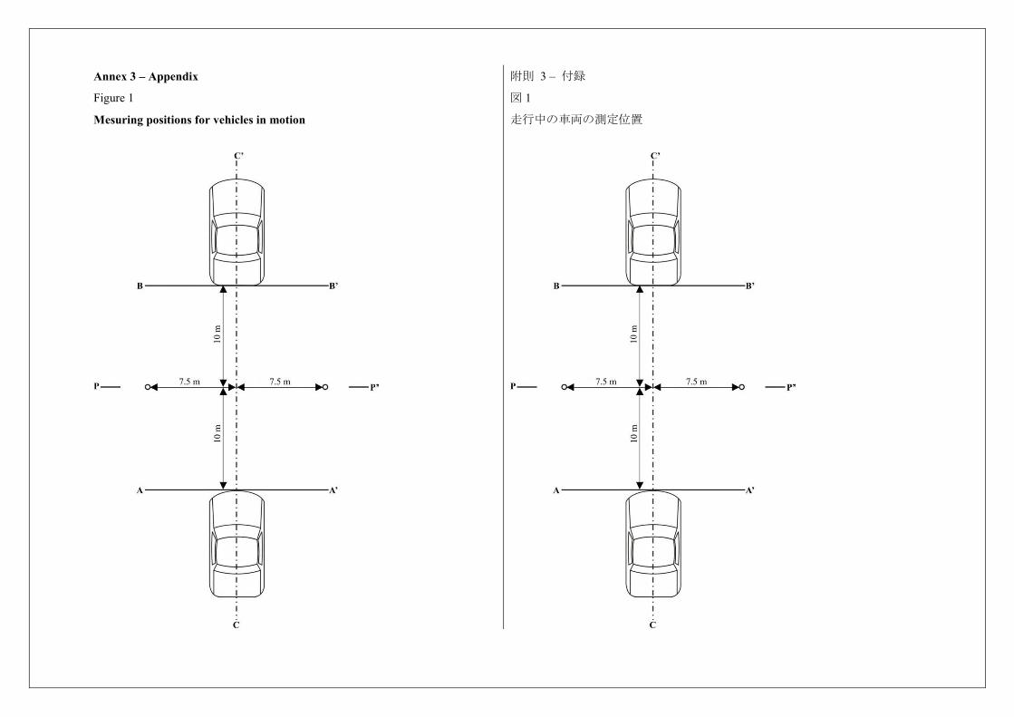
Annex 3 – Appendix
Figure 1
Mesuring positions for vehicles in motion
附則 3 – 付録
図 1
走行中の車両の測定位置
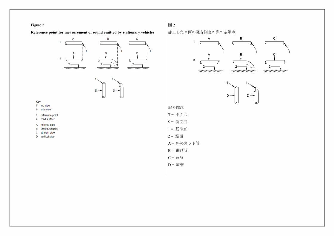
Figure 2
Reference point for measurement of sound emitted by stationary vehicles
図 2
静止した車両の騒音測定の際の基準点
記号解説
T = 平面図
S = 側面図
1 = 基準点
2 = 路面
A = 斜めカット管
B = 曲げ管
C = 直管
D = 縦管
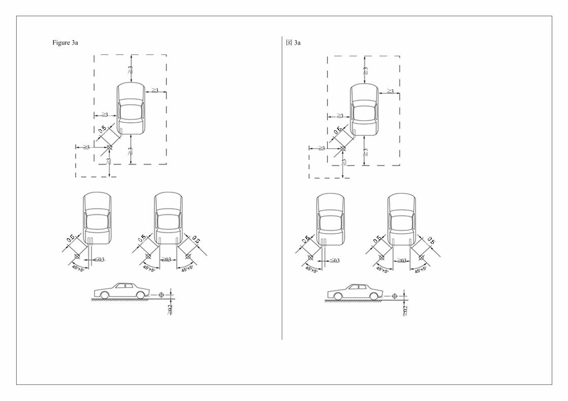
Figure 3a
図 3a
≧3
≧3
≧3
≧3
≦0.3
≧3
≧3
≧0.3
≧0.2
≧3
≧3
≧3
≧3
≦0.3
≧3
≧3
≧0.3
≧0.2
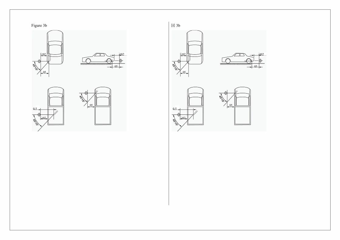
Figure 3b
図 3b
≧0.2
≧0.2
0.5
0.5 0.5
0.5
≧0.2
≧0.2
≧0.2
0.5
0.5 0.5
0.5
≧0.2
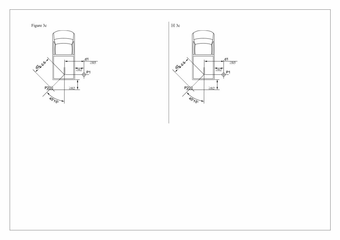
Figure 3c
図 3c
≧0.2
≧0.2
≧0.5
≧0.2
≧0.2 ≧0.2
≧0.2
≧0.5
≧0.2
≧0.2
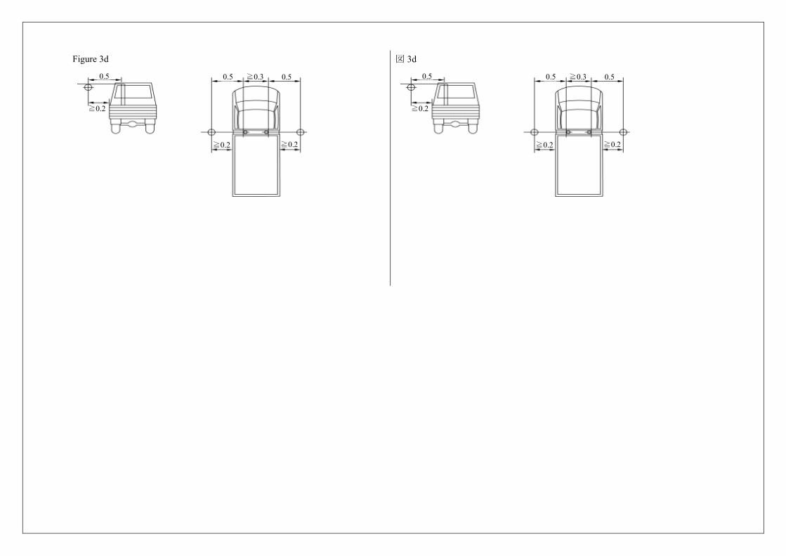
Figure 3d
0.5 0.5 ≧0.3 0.5
≧0.2
≧0.2
≧0.2
図 3d
0.5 0.5 ≧0.3 0.5
≧0.2
≧0.2
≧0.2
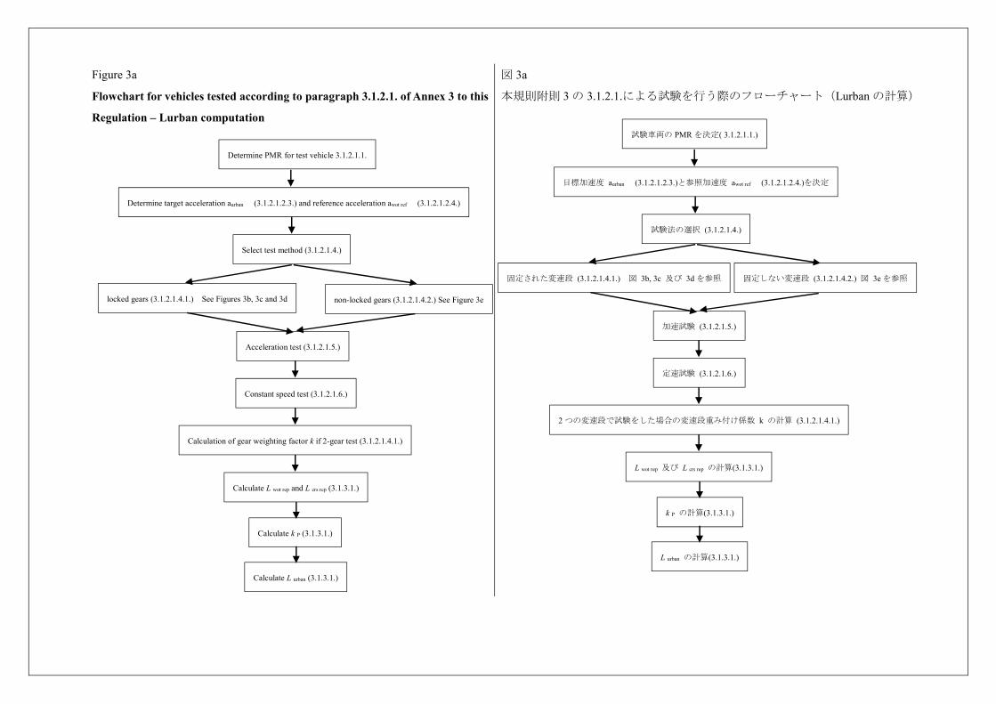
Figure 3a
Flowchart for vehicles tested according to paragraph 3.1.2.1. of Annex 3 to this
Regulation – Lurban computation
図 3a
本規則附則 3 の 3.1.2.1.による試験を行う際のフローチャート(Lurban の計算)
Determine PMR for test vehicle 3.1.2.1.1.
Determine target acceleration aurban (3.1.2.1.2.3.) and reference acceleration awot ref (3.1.2.1.2.4.)
Select test method (3.1.2.1.4.)
locked gears (3.1.2.1.4.1.) See Figures 3b, 3c and 3d non-locked gears (3.1.2.1.4.2.) See Figure 3e
Acceleration test (3.1.2.1.5.)
Constant speed test (3.1.2.1.6.)
Calculation of gear weighting factor k if 2-gear test (3.1.2.1.4.1.)
Calculate L wot rep and L crs rep (3.1.3.1.)
Calculate k P (3.1.3.1.)
Calculate L urban (3.1.3.1.)
試験車両の PMR を決定( 3.1.2.1.1.)
目標加速度 aurban (3.1.2.1.2.3.)と参照加速度 awot ref (3.1.2.1.2.4.)を決定
試験法の選択 (3.1.2.1.4.)
固定された変速段 (3.1.2.1.4.1.) 図 3b, 3c 及び 3d を参照 固定しない変速段 (3.1.2.1.4.2.) 図 3e を参照
加速試験 (3.1.2.1.5.)
定速試験 (3.1.2.1.6.)
2 つの変速段で試験をした場合の変速段重み付け係数 k の計算 (3.1.2.1.4.1.)
L wot rep 及び L crs rep の計算(3.1.3.1.)
k P の計算(3.1.3.1.)
L urban の計算(3.1.3.1.)
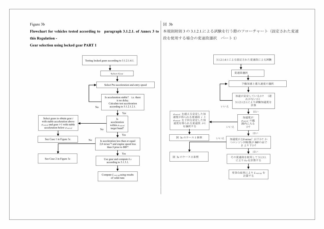
Figure 3b
Flowchart for vehicles tested according to paragraph 3.1.2.1. of Annex 3 to
this Regulation -
Gear selection using locked gear PART 1
図 3b
本規則附則 3 の 3.1.2.1.による試験を行う際のフローチャート(固定された変速
段を使用する場合の変速段選択 パート 1)
Yes
No
No
No
Yes
Yes
Testing locked gears according to 3.1.2.1.4.1.
Select Gear
Select Pre-acceleration and entry speed
Select gears to obtain gear i with stable acceleration above a wot ref and gear i+1 with stable
acceleration below a wot ref
Is acceleration stable? i.e. there is no delay.
Calculate test acceleration according to 3.1.2.1.2.1.
Is acceleration within a wot ref target band?
See Case 1 in Figure 3c Is acceleration less than or equal
2,0 m/sec2? and engine speed less than S prior to BB'?
See Case 2 in Figure 3c Use gear and compute k P according to 3.1.3.1.
Compute L wot rep using results of valid runs
はい
いいえ
いいえ
いいえ
はい
はい
3.1.2.1.4.1 による固定された変速段による試験
変速段選択
予備加速と進入速度の選択
a wot ref を超える安定した加速度が得られる変速段 i とa wot ref を下回る安定した加速度を得られる変速段 i+1
を選択する
加速が安定しているか? (遅れがないか)
3.1.2.1.2.1.により試験加速度を計算
加速度が a wot ref の範囲内に入る
か?
図 3c のケース1参照 加速度が 2,0 m/sec2 以下か? か
つエンジン回転数が BB'の前でS より下か?
図 3c のケース2参照 その変速段を使用して 3.1.3.1.により k Pを計算する
有効な結果により L wot rep を計算する
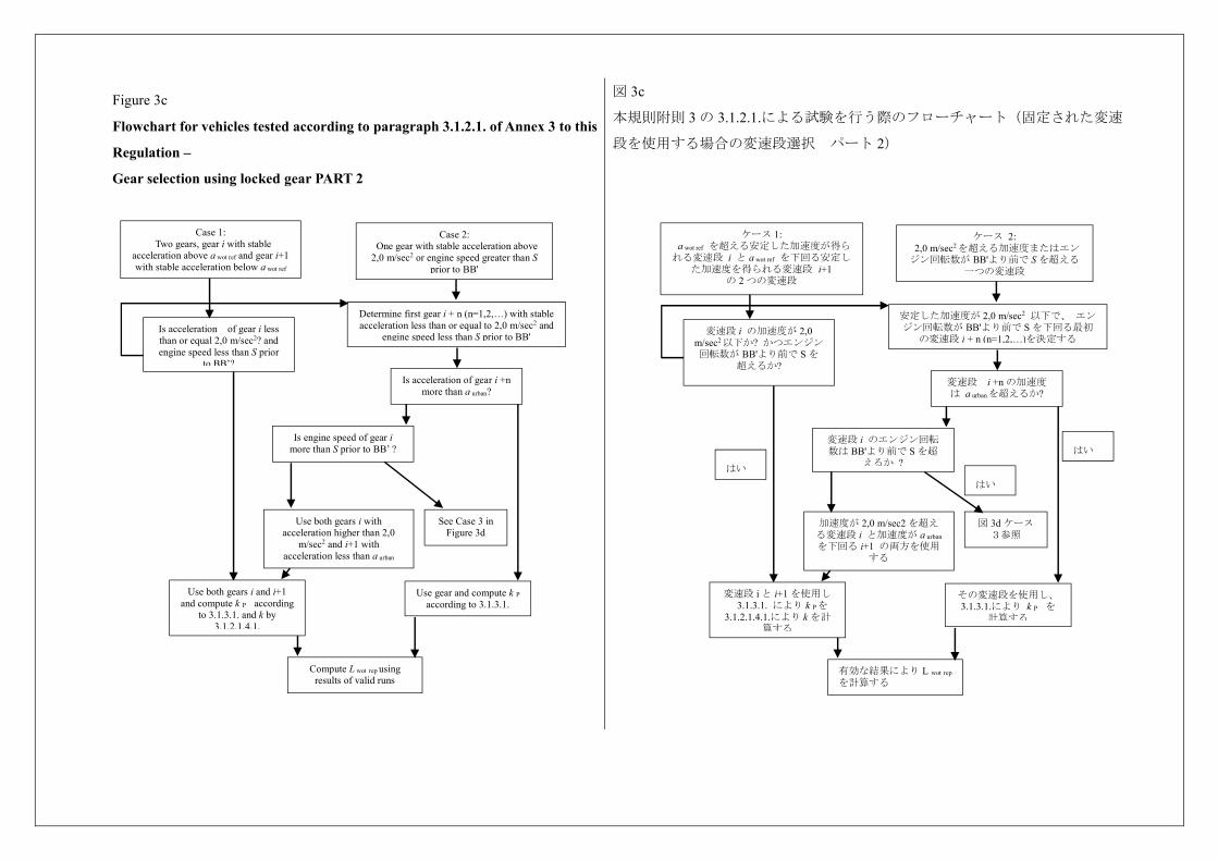
Figure 3c
Flowchart for vehicles tested according to paragraph 3.1.2.1. of Annex 3 to this
Regulation –
Gear selection using locked gear PART 2
図 3c
本規則附則 3 の 3.1.2.1.による試験を行う際のフローチャート(固定された変速
段を使用する場合の変速段選択 パート 2)
Is engine speed of gear i more than S prior to BB’ ?
Is acceleration of gear i +n more than a urban?
Determine first gear i + n (n=1,2,…) with stable acceleration less than or equal to 2,0 m/sec2 and
engine speed less than S prior to BB'
Case 2: One gear with stable acceleration above 2,0 m/sec2 or engine speed greater than S
prior to BB'
Case 1: Two gears, gear i with stable
acceleration above a wot ref and gear i+1 with stable acceleration below a wot ref
Is acceleration of gear i less than or equal 2,0 m/sec2? and engine speed less than S prior
to BB’?
Use both gears i with acceleration higher than 2,0
m/sec2 and i+1 with acceleration less than a urban
Use gear and compute k P according to 3.1.3.1.
See Case 3 in Figure 3d
Use both gears i and i+1 and compute k P according
to 3.1.3.1. and k by 3.1.2.1.4.1.
Compute L wot rep using results of valid runs
変速段 i のエンジン回転数は BB'より前で S を超
えるか ?
変速段 i +n の加速度は a urbanを超えるか?
安定した加速度が 2,0 m/sec2 以下で、 エンジン回転数が BB'より前で S を下回る最初
の変速段 i + n (n=1,2,…)を決定する
ケース 2: 2,0 m/sec2を超える加速度またはエンジン回転数が BB'より前で S を超える
一つの変速段
ケース 1: a wot ref を超える安定した加速度が得られる変速段 i と a wot ref を下回る安定し
た加速度を得られる変速段 i+1 の 2 つの変速段
変速段 i の加速度が 2,0 m/sec2 以下か? かつエンジン回転数が BB'より前で S を
超えるか?
加速度が 2,0 m/sec2 を超える変速段 i と加速度が a urban を下回る i+1 の両方を使用
する
その変速段を使用し、3.1.3.1.により k P を
計算する
図 3d ケース3参照
変速段 i と i+1 を使用し 3.1.3.1. により k Pを 3.1.2.1.4.1.により k を計
算する
有効な結果により L wot rep を計算する
はい
はい
はい
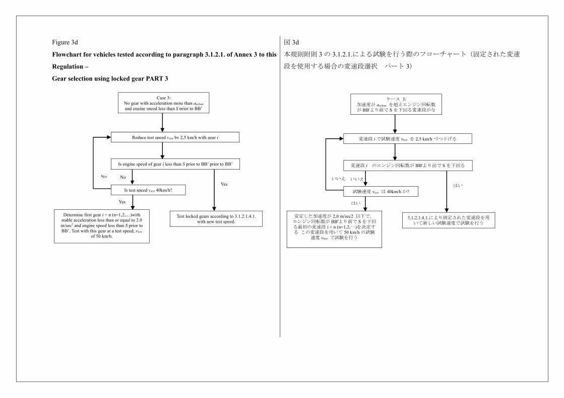
Figure 3d
Flowchart for vehicles tested according to paragraph 3.1.2.1. of Annex 3 to this
Regulation –
Gear selection using locked gear PART 3
図 3d
本規則附則 3 の 3.1.2.1.による試験を行う際のフローチャート(固定された変速
段を使用する場合の変速段選択 パート 3)
No No
Case 3: No gear with acceleration more than aurban and engine speed less than S prior to BB’
Reduce test speed vtest by 2,5 km/h with gear i
Is engine speed of gear i less than S prior to BB’ prior to BB’
Is test speed vtest 40km/h?
Yes
Determine first gear i + n (n=1,2,…)with stable acceleration less than or equal to 2.0 m/sec2 and engine speed less than S prior to BB’. Test with this gear at a test speed, vtest
of 50 km/h.
Test locked gears according to 3.1.2.1.4.1. with new test speed.
Yes いいえ いいえ
ケース 3: 加速度が aurban を超えエンジン回転数が BB'より前で S を下回る変速段がな
変速段 i で試験速度 vtest を 2,5 km/h づつ下げる
変速段 i のエンジン回転数が BB'より前で S を下回る
試験速度 vtest は 40km/h か?
はい
安定した加速度が 2,0 m/sec2 以下で、 エンジン回転数が BB'より前で S を下回る最初の変速段 i + n (n=1,2,…)を決定する この変速段を用いて 50 km/h の試験
速度 vtest で試験を行う
3.1.2.1.4.1.により固定された変速段を用いて新しい試験速度で試験を行う
はい
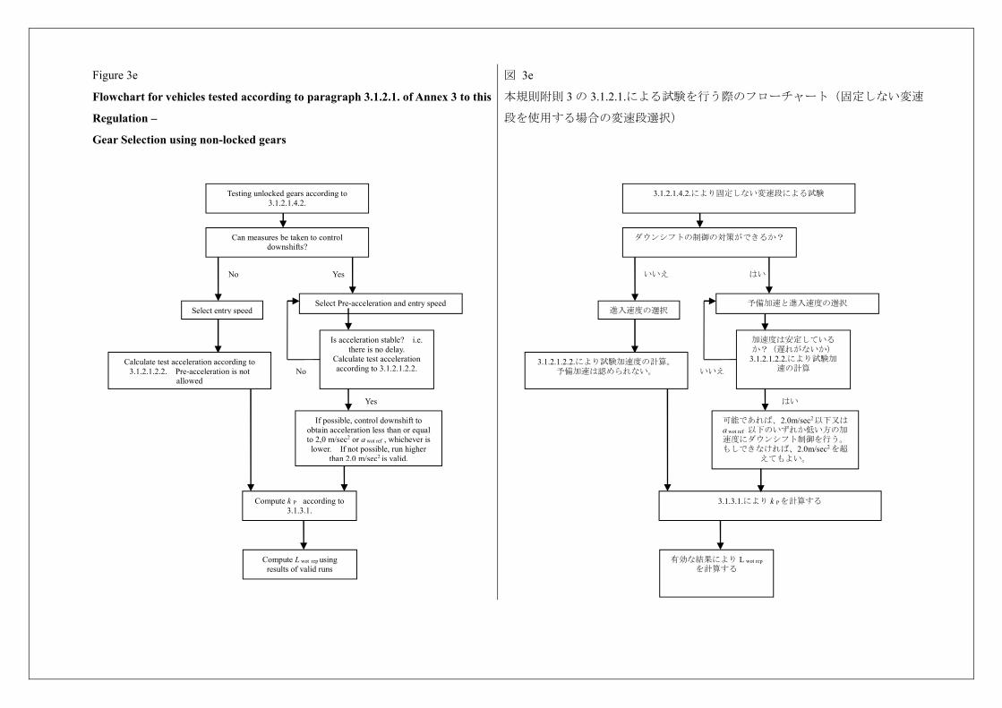
Figure 3e
Flowchart for vehicles tested according to paragraph 3.1.2.1. of Annex 3 to this
Regulation –
Gear Selection using non-locked gears
図 3e
本規則附則 3 の 3.1.2.1.による試験を行う際のフローチャート(固定しない変速
段を使用する場合の変速段選択)
YesNo
Compute L wot rep using results of valid runs
Calculate test acceleration according to 3.1.2.1.2.2. Pre-acceleration is not
allowed
Compute k P according to 3.1.3.1.
Can measures be taken to control downshifts?
Is acceleration stable? i.e. there is no delay.
Calculate test acceleration according to 3.1.2.1.2.2.
Select Pre-acceleration and entry speed
No
Yes
If possible, control downshift to obtain acceleration less than or equal to 2,0 m/sec2 or a wot ref , whichever is lower. If not possible, run higher
than 2,0 m/sec2 is valid.
Testing unlocked gears according to 3.1.2.1.4.2.
Select entry speed
はい いいえ
有効な結果により L wot rep を計算する
3.1.2.1.2.2.により試験加速度の計算。 予備加速は認められない。
3.1.3.1.により k Pを計算する
ダウンシフトの制御の対策ができるか?
加速度は安定しているか?(遅れがないか)
3.1.2.1.2.2.により試験加速の計算
予備加速と進入速度の選択
いいえ
はい
可能であれば、2.0m/sec2以下又はa wot ref 以下のいずれか低い方の加速度にダウンシフト制御を行う。もしできなければ、2.0m/sec2 を超
えてもよい。
3.1.2.1.4.2.により固定しない変速段による試験
進入速度の選択
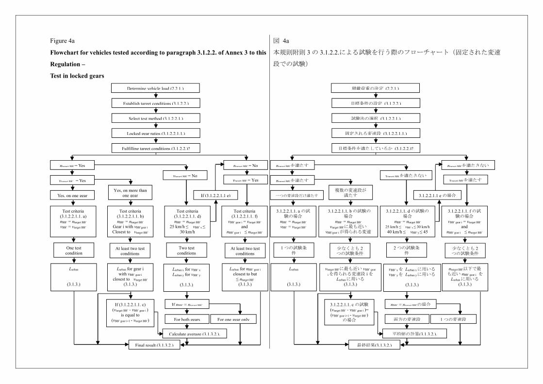
Figure 4a
Flowchart for vehicles tested according to paragraph 3.1.2.2. of Annex 3 to this
Regulation –
Test in locked gears
図 4a
本規則附則 3 の 3.1.2.2.による試験を行う際のフローチャート(固定された変速
段での試験)
Yes, on one gear
Determine vehicle load (2.2.1.)
Establish target conditions (3.1.2.2.)
Select test method (3.1.2.2.1.)
Locked gear ratios (3.1.2.2.1.1.)
Fulfilling target conditions (3.1.2.2.)?
ntarget BB’ = Yes
vtarget BB’ = Yes
ntarget BB’ = No
vtarget BB’ = Yes vtarget BB’ = No
If (3.1.2.2.1.1 e) Yes, on more than
one gear
Test criteria (3.1.2.2.1.1. a) nBB’ = ntarget BB’ vBB’ = vtarget BB’
Test criteria (3.1.2.2.1.1. b) nBB’ = ntarget BB’
Gear i with vBB’gear i Closest to vtarget BB’
Test criteria (3.1.2.2.1.1. d) nBB’ = ntarget BB’
25 km/h ≤ vBB’ x ≤ 30 km/h
40 km/h ≤ ≤
Test criteria (3.1.2.2.1.1. f)
vBB’ gear i = vtarget BB’ and
nBB’ gear i ≤ ntarget BB’
One test condition
At least two test conditions
Two test conditions
At least two test conditions
Lurban
(3.1.3.)
Lurban for gear i with vBB’ gear i
closest to vtarget BB’ (3.1.3.)
Lurban x for vBB’ x Lurban y for vBB’ y
(3.1.3.)
Lurban for nBB’ gear i closest to but
≤ ntarget BB’ (3.1.3.)
If (3.1.2.2.1.1. c) (vtarget BB’ - vBB’ gear i )
is equal to (vBB’ gear i+1 - vtarget BB’)
If nBB’ = ntarget BB’
For both gears For one gear only
Calculate average (3.1.3.2.).
Final result (3.1.3.2.)
一つの変速段だけ満たす
積載荷重の決定 (2.2.1.)
目標条件の設定 (3.1.2.2.)
試験法の選択 (3.1.2.2.1.)
固定される変速段 (3.1.2.2.1.1.)
目標条件を満たしているか (3.1.2.2.)?
ntarget BB’を満たす
ntarget BB’を満たす
ntarget BB’を満たさない
vtarget BB’を満たす vtarget BBを満たさない
3.1.2.2.1.1 e の場合 複数の変速段が
満たす
3.1.2.2.1.1. a の試験の場合
nBB’ = ntarget BB’ vBB’ = vtarget BB’
3.1.2.2.1.1. b の試験の場合
nBB’ = ntarget BB’ vtarget BB’に最も近い
vBB’gear iが得られる変速i
3.1.2.2.1.1. d の試験の場合
nBB’ = ntarget BB’ 25 km/h ≤ vBB’ x ≤ 30 km/h 40 km/h ≤ vBB’ y ≤ 45
km/h
3.1.2.2.1.1. f の試験の場合
vBB’ gear i = vtarget BB’ and
nBB’ gear i ≤ ntarget BB’
1 つの試験条件
少なくとも 2つの試験条件
2 つの試験条件
少なくとも 2つの試験条件
Lurban
(3.1.3.)
vtarget BB’に最も近い vBB’ gear
iを得られる変速段 i を Lurbanに用いる
(3.1.3.)
vBB’ xを Lurban xに用いる vBB’ yを Lurban yに用いる
(3.1.3.)
ntarget BB’以下で最も近い nBB’ gear i を
Lurbanに用いる (3.1.3.)
3.1.2.2.1.1. c の試験 (vtarget BB’ - vBB’ gear i )= (vBB’ gear i+1 - vtarget BB’)
の場合
nBB’ = ntarget BB’の場合
両方の変速段 1 つの変速段
平均値の計算(3.1.3.2.).
最終結果(3.1.3.2.)
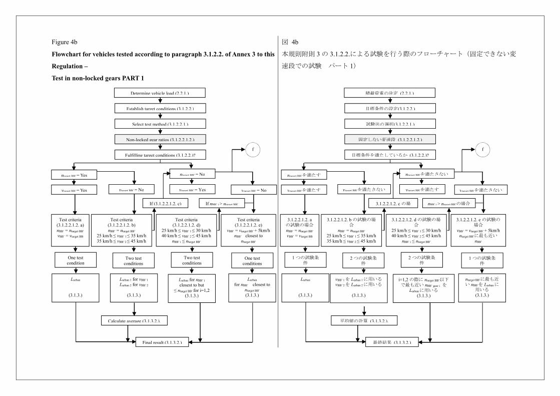
Figure 4b
Flowchart for vehicles tested according to paragraph 3.1.2.2. of Annex 3 to this
Regulation –
Test in non-locked gears PART 1
図 4b
本規則附則 3 の 3.1.2.2.による試験を行う際のフローチャート(固定できない変
速段での試験 パート 1)
Determine vehicle load (2.2.1.)
Establish target conditions (3.1.2.2.)
Select test method (3.1.2.2.1.)
Non-locked gear ratios (3.1.2.2.1.2.)
Fulfilling target conditions (3.1.2.2.)?
ntarget BB’ = Yes
vtarget BB’ = No vtarget BB’ = No vtarget BB’ = Yes vtarget BB’ = Yes
If nBB’ i > ntarget BB’
Test criteria (3.1.2.2.1.2. a) nBB’ = ntarget BB’ vBB’ = vtarget BB
Test criteria (3.1.2.2.1.2. b) nBB’ = ntarget BB’
25 km/h ≤ vBB’ 1 ≤ 35 km/h 35 km/h ≤ vBB’ 2 ≤ 45 km/h
Test criteria (3.1.2.2.1.2. d)
25 km/h ≤ vBB’ 1 ≤ 30 km/h 40 km/h ≤ vBB’ 2 ≤ 45 km/h
nBB’ i ≤ ntarget BB’ 40 km/h ≤ ≤ 45
Test criteria (3.1.2.2.1.2. e)
vBB’ = vtarget BB’ + 5km/h nBB’ closest to
ntarget BB’
One test condition
Two test conditions
Two test conditions
One test conditions
f
ntarget BB’ = No
If (3.1.2.2.1.2. c)
Lurban
(3.1.3.)
Lurban 1 for vBB’ 1 Lurban 2 for vBB’ 2
(3.1.3.)
Lurban for nBB’ i closest to but
≤ ntarget BB’ for i=1,2 (3.1.3.)
Lurban for nBB’ closest to
ntarget BB’ (3.1.3.)
Calculate average (3.1.3.2.).
Final result (3.1.3.2.)
積載荷重の決定 (2.2.1.)
目標条件の設定(3.1.2.2.)
試験法の選択(3.1.2.2.1.)
固定しない変速段 (3.1.2.2.1.2.)
目標条件を満たしているか (3.1.2.2.)?
ntarget BB’を満たす
vtarget BB’を満たさない vtarget BB’を満たさない vtarget BB’を満たす vtarget BB’を満たす
nBB’ i > ntarget BB’の場合
3.1.2.2.1.2. aの試験の場合 nBB’ = ntarget BB’ vBB’ = vtarget BB
3.1.2.2.1.2. b の試験の場合
nBB’ = ntarget BB’ 25 km/h ≤ vBB’ 1 ≤ 35 km/h 35 km/h ≤ vBB’ 2 ≤ 45 km/h
3.1.2.2.1.2. d の試験の場合
25 km/h ≤ vBB’ 1 ≤ 30 km/h 40 km/h ≤ vBB’ 2 ≤ 45 km/h
nBB’ i ≤ ntarget BB’ 40 km/h ≤ ≤ 45
3.1.2.2.1.2. e の試験の場合
vBB’ = vtarget BB’ + 5km/h ntarget BB’に最も近い
nBB’
1 つの試験条件
2 つの試験条件
2 つの試験条件
1 つの試験条件
f
ntarget BB’を満たさない
3.1.2.2.1.2. c の場
Lurban
(3.1.3.)
vBB’ 1を Lurban 1に用いる vBB’ 2を Lurban 2に用いる
(3.1.3.)
i=1,2 の際に ntarget BB’以下で最も近い nBB’ gear i を
Lurbanに用いる (3.1.3.)
ntarget BB’に最も近い nBB’を Lurbanに
用いる (3.1.3.)
平均値の計算 (3.1.3.2.).
最終結果 (3.1.3.2.)
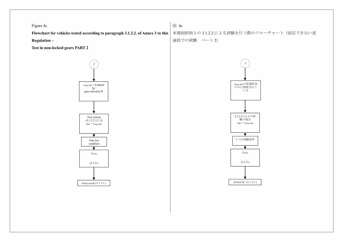
Figure 4c
Flowchart for vehicles tested according to paragraph 3.1.2.2. of Annex 3 to this
Regulation –
Test in non-locked gears PART 2
図 4c
本規則附則 3 の 3.1.2.2.による試験を行う際のフローチャート(固定できない変
速段での試験 パート 2)
vtarget BB’ = Limited by
gear selection D
One test condition
Lurban
(3.1.3.)
f
Final result (3.1.3.2.)
Test criteria (3.1.2.2.1.2. f) vBB’ = vtarget BB’
vtarget BB’が変速段 Dのみに制限されて
いる
1 つの試験条件
Lurban
(3.1.3.)
f
最終結果 (3.1.3.2.)
3.1.2.2.1.2. f の試験の場合
vBB’ = vtarget BB’
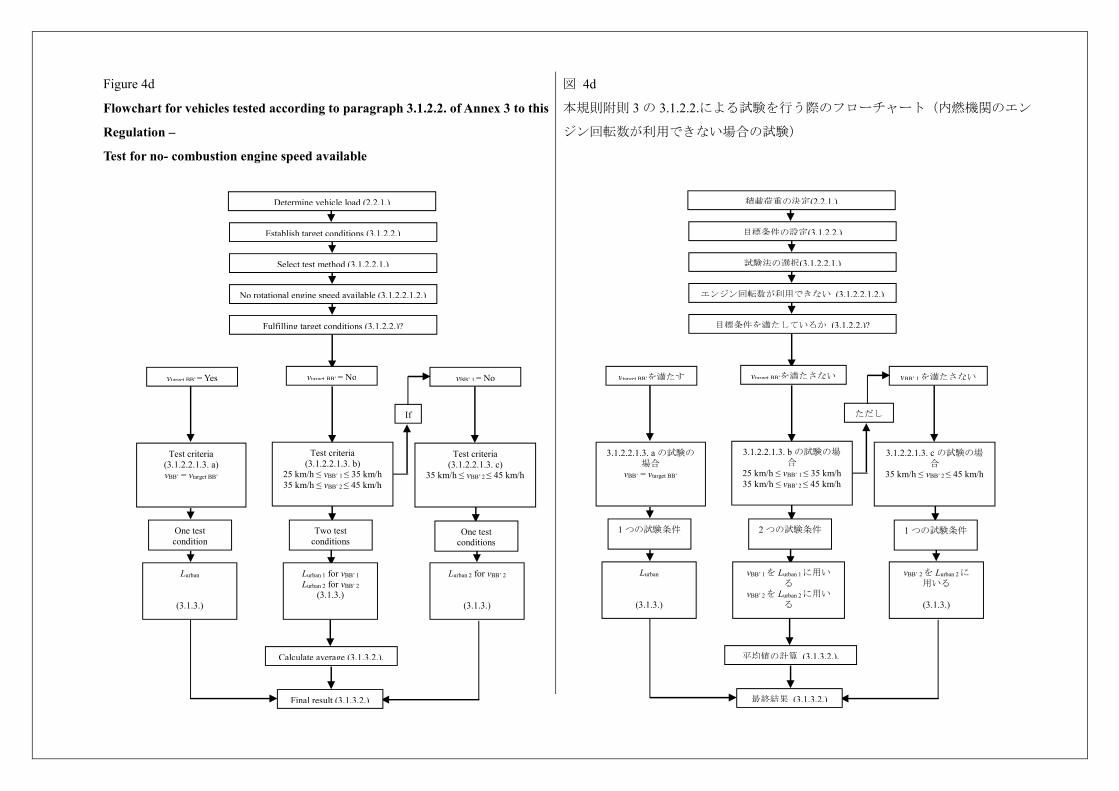
Figure 4d
Flowchart for vehicles tested according to paragraph 3.1.2.2. of Annex 3 to this
Regulation –
Test for no- combustion engine speed available
図 4d
本規則附則 3 の 3.1.2.2.による試験を行う際のフローチャート(内燃機関のエン
ジン回転数が利用できない場合の試験)
Determine vehicle load (2.2.1.)
Establish target conditions (3.1.2.2.)
Select test method (3.1.2.2.1.)
No rotational engine speed available (3.1.2.2.1.2.)
Fulfilling target conditions (3.1.2.2.)?
vBB’ 1 = No vtarget BB’ = No vtarget BB’ = Yes
If
Test criteria (3.1.2.2.1.3. a) vBB’ = vtarget BB’
Test criteria (3.1.2.2.1.3. b)
25 km/h ≤ vBB’ 1 ≤ 35 km/h 35 km/h ≤ vBB’ 2 ≤ 45 km/h
Test criteria (3.1.2.2.1.3. c)
35 km/h ≤ vBB’ 2 ≤ 45 km/h
One test condition
Two test conditions
One test conditions
Lurban
(3.1.3.)
Lurban 1 for vBB’ 1 Lurban 2 for vBB’ 2
(3.1.3.)
Lurban 2 for vBB’ 2
(3.1.3.)
Calculate average (3.1.3.2.).
Final result (3.1.3.2.)
積載荷重の決定(2.2.1.)
目標条件の設定(3.1.2.2.)
試験法の選択(3.1.2.2.1.)
エンジン回転数が利用できない (3.1.2.2.1.2.)
目標条件を満たしているか (3.1.2.2.)?
vBB’ 1を満たさない vtarget BB’を満たさない vtarget BB’を満たす
ただし
3.1.2.2.1.3. a の試験の場合
vBB’ = vtarget BB’
3.1.2.2.1.3. b の試験の場合
25 km/h ≤ vBB’ 1 ≤ 35 km/h 35 km/h ≤ vBB’ 2 ≤ 45 km/h
3.1.2.2.1.3. c の試験の場合
35 km/h ≤ vBB’ 2 ≤ 45 km/h
1 つの試験条件
2 つの試験条件
1 つの試験条件
Lurban
(3.1.3.)
vBB’ 1を Lurban 1に用いる
vBB’ 2を Lurban 2に用いる
vBB’ 2を Lurban 2に用いる
(3.1.3.)
平均値の計算 (3.1.3.2.).
最終結果 (3.1.3.2.)
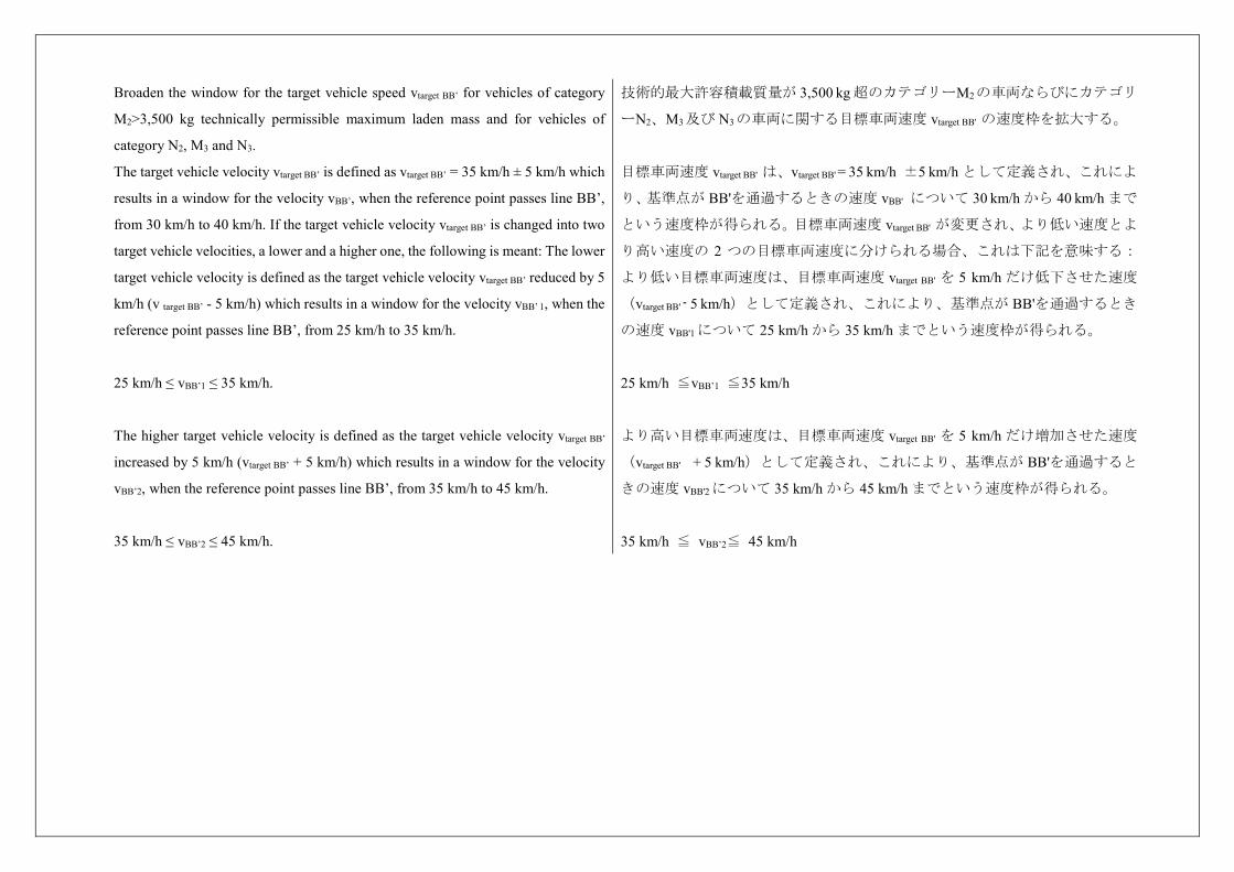
Broaden the window for the target vehicle speed vtarget BB’ for vehicles of category
M2>3,500 kg technically permissible maximum laden mass and for vehicles of
category N2, M3 and N3.
The target vehicle velocity vtarget BB’ is defined as vtarget BB’ = 35 km/h ± 5 km/h which
results in a window for the velocity vBB’, when the reference point passes line BB’,
from 30 km/h to 40 km/h. If the target vehicle velocity vtarget BB’ is changed into two
target vehicle velocities, a lower and a higher one, the following is meant: The lower
target vehicle velocity is defined as the target vehicle velocity vtarget BB’ reduced by 5
km/h (v target BB’ - 5 km/h) which results in a window for the velocity vBB’ 1, when the
reference point passes line BB’, from 25 km/h to 35 km/h.
25 km/h ≤ vBB’1 ≤ 35 km/h.
The higher target vehicle velocity is defined as the target vehicle velocity vtarget BB’
increased by 5 km/h (vtarget BB’ + 5 km/h) which results in a window for the velocity
vBB’2, when the reference point passes line BB’, from 35 km/h to 45 km/h.
35 km/h ≤ vBB’2 ≤ 45 km/h.
技術的最大許容積載質量が 3,500 kg 超のカテゴリーM2の車両ならびにカテゴリ
ーN2、M3及び N3の車両に関する目標車両速度 vtarget BB' の速度枠を拡大する。
目標車両速度 vtarget BB' は、vtarget BB' = 35 km/h ±5 km/h として定義され、これによ
り、基準点が BB'を通過するときの速度 vBB' について 30 km/h から 40 km/h まで
という速度枠が得られる。目標車両速度 vtarget BB' が変更され、より低い速度とよ
り高い速度の 2 つの目標車両速度に分けられる場合、これは下記を意味する:
より低い目標車両速度は、目標車両速度 vtarget BB' を 5 km/h だけ低下させた速度
(vtarget BB' - 5 km/h)として定義され、これにより、基準点が BB'を通過するとき
の速度 vBB'1 について 25 km/h から 35 km/h までという速度枠が得られる。
25 km/h ≦vBB’1 ≦35 km/h
より高い目標車両速度は、目標車両速度 vtarget BB' を 5 km/h だけ増加させた速度
(vtarget BB' + 5 km/h)として定義され、これにより、基準点が BB'を通過すると
きの速度 vBB'2 について 35 km/h から 45 km/h までという速度枠が得られる。
35 km/h ≦ vBB’2≦ 45 km/h
Annex 4 Exhaust silencing systems containing acoustically absorbing fibrous
materials
附則4 繊維性吸音材料を含む排気消音システム
1. General
Sound absorbing fibrous materials may be used in silencing systems or components
thereof only if
1. 一般要件
以下の場合に限り、繊維性吸音材料を消音システム又はその構成部品に使用す
ることができる。
(a) The exhaust gas is not in contact with the fibrous materials; or if (a) 排気ガスが当該繊維性材料と直接触れない、又は
(b) The silencing system or components thereof are of the same design family as
systems or components for which it has been proven, in the course of type approval
process in accordance with the requirements of this regulation for another vehicle-
type, that they are not subject to deterioration.
(b) 消音システム又は構成部品が、本規則の要件に従った型式認可で劣化しに
くいことが証明されている別の型式車両のシステム又は構成部品と、同じ設計
思想の場合。
Unless one of these conditions is fulfilled, the complete silencing system or
components thereof shall be submitted to a conventional conditioning using one of
three installations and procedures described below.
いづれにも該当しない場合に限り、消音システムの全体又はその構成部品は、
以下に記載されている三つの試験の一つを用いて、決められた条件に適合させ
なければいけない。
1.1. Continuous road operation for 10,000 km 1.1. 10,000 km の連続道路走行
1.1.1. 50 ± 20 per cent of this operation shall consist of urban driving and the
remaining operation shall be long-distance runs at high speed; continuous road
operation may be replaced by a corresponding test-track programme.
1.1.1. 走行の50 ± 20 %は市街地走行とし、残りの走行は高速での長距離走行と
しなければならない。この試験は、対応する試験走行路での試験に代えること
ができる。
1.1.2. The two speed regimes shall be alternated at least twice. 1.1.2. この2 種類の速度域の試験は、少なくとも2回は、交互に行なわなけれ
ばいけない。
1.1.3. The complete test programme shall include a minimum of 10 breaks of at
least three hours duration in order to reproduce the effects of cooling and any
condensation which may occur.
1.1.3. 冷却の効果と、それにより生じる可能性のある結露を再現するために、
試験は、少なくとも3 時間の停止を最低10 回含むものとする。
1.2. Conditioning on a test bench 1.2.台上試験でのコンディショニング
1.2.1. Using standard parts and observing the vehicle manufacturer's instructions,
the silencing system or components thereof shall be fitted to the vehicle referred to
in paragraph 3.3. of this Regulation or the engine referred to in paragraph 3.4. of
1.2.1. 標準部品を使い、自動車製作者等の指示に従って、消音システム又はそ
の構成部品を、本規則の3.3.で言及した車両又は本規則の3.4.で言及した原動機
に取り付けなければならない。前者の場合は、車両をローラーダイナモメータ
this Regulation. In the former case the vehicle shall be mounted on a roller
dynamometer. In the second case, the engine shall be coupled to a dynamometer.
ーに取り付け、後者の場合は、原動機をダイナモメーターに接続するものとす
る。
1.2.2. The test shall be conducted in six six-hour periods with a break of at least 12
hours between each period in order to reproduce the effects of cooling any
condensation which may occur.
1.2.2. 冷却の効果と,それによって生じる可能性のある結露を再現するために、
6時間の試験を6 回実施し、その各試験の間には少なくとも12 時間の機関停止
を行うものとする。
1.2.3. During each six-hour period, the engine shall be run, under the following
conditions:
1.2.3. 6時間の試験では、原動機を下記の条件で運転するものとする。
(a) Five minutes at idling speed; (a) アイドリング回転数で5 分間、
(b) One-hour sequence under 1/4 load at 3/4 of rated maximum speed (S); (b) 定格エンジン回転数(S)の3/4 で、1/4 の負荷で連続1 時間、
(c) One-hour sequence under 1/2 load at 3/4 of rated maximum speed (S); (c) 定格エンジン回転数(S)の3/4 で、1/2 の負荷で連続1 時間、
(d) 10-minute sequence under full load at 3/4 of rated maximum speed (S); (d) 定格エンジン回転数(S)の3/4 で、全負荷で連続10 分間、
(e) 15-minute sequence under 1/2 load at rated maximum speed (S); (e) 定格エンジン回転数(S)で、1/2 の負荷で連続15 分間、
(f) 30-minute sequence under 1/4 load at rated maximum speed (S). (f) 定格エンジン回転数(S)で、1/4 の負荷で連続30 分間。
Each period shall comprise two sequenced sets of the six above-mentioned
conditions in consecutive order from (a) to (f).
6時間の試験は、(a) から(f) の順番に従って、連続した2回で実施する。
1.2.4. During the test, the silencing system or components thereof shall not be
cooled by a forced draught simulating normal airflow around the vehicle.
Nevertheless, at the request of the manufacturer, the silencing system or
components thereof may be cooled in order not to exceed the temperature recorded
at its inlet when the vehicle is running at maximum speed.
1.2.4. 試験中、消音システム又はその構成部品は、車両周囲の通常気流を再現
するための送風で冷却しないものとする。ただし、自動車製作者等の申請があ
れば、当該システム又は構成部品の先端部分で、車両が最高速度で走行してい
るときに記録した温度を超えないようにするために、消音システム又はその構
成部品を冷却してもよい。
1.3. Conditioning by pulsation 1.3. パルセーションによる試験コンディショニング
1.3.1. The silencing system or components thereof shall be fitted to the vehicle
referred to in paragraph 3.3. of this Regulation or the engine referred to in
paragraph 3.4. of this Regulation. In the former case the vehicle shall be mounted
on a roller dynamometer.
In the second case, the engine shall be mounted on a dynamometer. The test
1.3.1. 消音システム又はその構成部品を、本規則の3.3.で言及した車両又は本
規則の3.4.に言及した原動機に取り付けるものとする。前者の場合は、車両を
ローラーダイナモメーターに取り付けなければならない。後者の場合は、原動
機をダイナモメーターに取り付けなければならない。試験装置(詳細図を本附
則、付録の図1 に示す)は、消音システムの排気口に取り付けなければならな
apparatus, a detailed diagram of which is shown in Figure 1 of the appendix to this
annex shall be fitted at the outlet of the silencing system. Any other apparatus
providing equivalent results is acceptable.
い。また、同等の結果を得ることができる試験装置でも試験可とする。
1.3.2. The test apparatus shall be adjusted in such a way that the exhaust-gas flow
is alternatively interrupted and re-established by the quick-action valve for 2,500
cycles.
1.3.2. 試験装置は、急動バルブによる排気ガス流の遮断と解放を2,500回繰り返
すように、調整されているものとする。
1.3.3. The valve shall open when the exhaust-gas back pressure, measured at least
100 mm downstream of the intake flange, reaches a value of between 35 and 40
kPa. It shall close when this pressure does not differ by more than 10 per cent from
its stabilized value with the valve open.
1.3.3. 排気ガスの背圧が(試験装置の)インテークフランジの少なくとも100 mm
下流で35 kPaから40 kPaの値に達した時に、バルブは開くものとする。バルブ
が開放状態のままで安定した圧力となる時に計測される値の10 %以下の圧力
となった時に、バルブは閉じるものとする。
1.3.4. The time-delay switch shall be set for the duration of gas exhaust resulting
from the provisions laid down in paragraph 1.3.3. above.
1.3.4. タイム・ディレー・スイッチは、上記1.3.3.に定めた規定の結果で生じる
ガス排出の時間に合わせて設定しなければならない。
1.3.5. Engine speed shall be 75 per cent of the rated engine speed (S) at which the
engine develops rated maximum net power.
1.3.5. エンジン回転数は、エンジン出力が最大となる回転数(S)の75 %とす
る。
1.3.6. The power indicated by the dynamometer shall be 50 per cent of the full-
throttle power measured at 75 per cent of rated engine speed (S).
1.3.6. ダイナモメーターが示す出力は、エンジン回転数(S)の75 %のエンジ
ン回転数で原動機を全加速状態で運転した時に測定したエンジン出力の50 %
とする。
1.3.7. Any drain holes shall be closed off during the test. 1.3.7. 試験中はすべての排水穴を閉じるものとする。
1.3.8. The entire test shall be completed within 48 hours.
If necessary, one cooling period will be observed after each hour.
1.3.8. 全ての試験を48 時間以内に完了するものとする。
必要であれば、1 時間ごとに1 回の冷却期間を設ける。
Annex 4 - Appendix 附則4−付録
Figure 1
Test apparatus for conditioning by pulsation
図 1
パルセーション装置の装置図
1. Inlet flange or sleeve for connection to the rear of the test exhaust system. 1. 試験対象の排気システムの後部に接続するインレットフランジ又はスリー
ブ。
2. Hand-operated regulating valve. 2. 手動式調整バルブ。
3. Compensating reservoir with a maximum capacity of 40 l and a filling time of
not less than one second.
3.最大容量が40リットルで、充填時間が1秒以上の(圧力)調整貯蔵容器。
4. Pressure switch with an operating range of 0.05 to 2.5 bar. 4. 作動領域が 5 kPa から 250 kPa の圧力スイッチ
5. Time delay switch. 5. タイム・ディレー・スイッチ
6. Pulse counter. 6.パルスカウンター。
7. Quick-acting valve, such as exhaust brake valve 60 mm in diameter, operated by
a pneumatic cylinder with an output of 120 N at 4 bar. The response time, both
when opening and closing, shall not exceed 0.5 second.
7. 400 kPa で 120 N を出力する空気シリンダーで作動する直径 60 mm の排気
ブレーキバルブと同等の速応バルブ。反応時間は、開閉どちらの場合も 0.5
秒を超えないものとする。
8. Exhaust gas evacuation. 8. 排ガス排出部。
9. Flexible pipe. 9. フレキシブルパイプ。
10. Pressure gauge. 10. 圧力ゲージ。
Annex 5 Compressed air noise 附則 5 圧縮空気の騒音
1. Method of measurement
The measurement is performed at microphone positions 2 and 6 according to
Figure 1, with the vehicle stationary. The highest A-weighted sound level is
registered during venting the pressure regulator and during ventilating after the use
of both the service and parking brakes.
The noise during venting the pressure regulator is measured with the engine at idling
speed. The ventilating noise is registered while operating the service and parking
brakes; before each measurement, the air-compressor unit has to be brought up to
the highest permissible operating pressure, and then the engine switched off.
1. 測定方法
測定は、車両が停止した状態で、図 1 に従って、マイクロホン位置 2 及び 6 で
行なう。圧力調整器のエア吐出中及び主制動装置と駐車制動装置の両方を使っ
た後の排出時における最大 A 特性音圧レベルを記録する。
圧力調整器のエア吐出中の騒音は、アイドリング時のエンジン回転数で測定す
る。主制動装置及び駐車制動装置の騒音測定を行なう前には、エアコンプレッ
サユニットは最大許容作動圧まで高め、次に原動機のスイッチを切り、各制動
装置が作動しているときに記録する。
2. Evaluation of the results
For all microphone positions two measurements are taken. In order to compensate
for inaccuracies of the measuring equipment, the meter reading is reduced by 1
dB(A), and the reduced value is taken as the result of measurement. The results are
taken as valid if the difference between the measurements at one microphone
position does not exceed 2 dB(A). The highest value measured is taken as the
result. If this value exceeds the sound limit by 1 dB(A), two additional
measurements are to be taken at the corresponding microphone position.
In this case, three out of the four results of measurement obtained at this position
have to comply with the sound limit.
2. 結果の評価
全てのマイクロホン位置について、2 回の測定を行なう。測定装置による誤差を
補正するために、騒音計の読み値は 1 dB(A)引き下げ、この値を測定結果とす
る。この結果は、1 つのマイクロホン位置における各測定の差が 2 dB(A)以下
のときに有効とする。測定された最大値を結果として記録する。もしこの値が
音量規制値を 1 dB(A)を超えて上回っている場合、対応するマイクロホン位
置でさらに 2 回の測定を行なうものとする。
この場合、この位置で得られた 4 回の測定結果のうち 3 回が音量規制値に適合
しなければならない。
3. Limiting value
The sound level shall not exceed the limit of 72 dB(A).
3. 規制値
音量レベルは 72 dB(A)の規制値を超えないものとする。
Annex 5 - Appendix 附則 5 – 付録
Figure 1:
Microphone positions for measurement of compressed air noise
The measurement is performed at the stationary vehicle according to Figure 1,
using two microphone positions at a distance of 7 m from the contour of the
vehicles, and at 1.2 m above ground.
図 1
圧縮空気騒音の測定におけるマイクロホンの位置
測定は図1に従い、車両の最外側から7mの距離、地上1.2mの位置の2つのマイ
クロホンを使用し、停止状態の車両で実施する。
microphone microphone マイクロホン マイクロホン
Annex 6 Checks on conformity of production 附則6 生産の適合性の検査
1. General
These requirements are consistent with the test for checking conformity of
production (COP) according to paragraph 8. of this Regulation.
1. 一般要件
これらの要件は、本規則の8項に従った生産の適合性(COP)検査のための試
験に相当するものである。
2. Testing procedure
The test site and measuring instruments shall be those as described in Annex 3.
2. 試験手順
試験場と測定計器は附則3に定めるとおりとする。
2.1. The vehicle(s) under test shall be subjected to the test for measurement of
sound of vehicle in motion as described in paragraph 3.1. of Annex 3.
2.1. 試験中の車両は、附則3の3.1.に記したとおり、走行中の車両の音量を測定
するものとする。
2.2. Compressed air noise
Vehicles having maximum mass exceeding 2,800 kg and equipped with
compressed air systems shall be subjected to an additional test for measurement of
the compressed air noise as described in paragraph 1. of Annex 5.
2.2. 圧縮空気騒音
最大質量が2,800 kgを超えかつ圧縮空気システムを搭載した車両は、附則5の1.に
記したとおり、圧縮空気騒音を追加して測定するものとする。
2.3. Additional sound emission provisions (ASEP)
The vehicle manufacturer shall assess the compliance with ASEP by an appropriate
evaluation (for example, but not limited to, part checks) or may perform the test
described in Annex 7.
2.3. 音の発生に関する追加規定(ASEP)
自動車製作者等は、適切な評価(部品検査など、ただしこれに限らない)によ
ってASEPとの適合性を評価するものとする。附則7に記載の試験を行ってもよ
い。
3. Sampling and evaluation of the results
One vehicle shall be chosen and subjected to the tests set out in point 2. If the
sound level of the vehicle tested does not exceed by more than 1 dB(A) the limit
value prescribed in Annex 3, and, where appropriate, paragraph 3. of Annex 5, the
vehicle type shall be considered to conform to the requirements of this Regulation.
If one of the test results does not fulfil the COP requirements of this annex and of
paragraph 8. of the main body of this Regulation two more vehicles of the same
type shall be tested pursuant to paragraph 2. above.
If the test results for the second and the third vehicle fulfil the COP requirements of
3. サンプリング及び結果の評価
1台の車両を選び2.に記載の試験を行わなければならない。試験した車両の音
量レベルが附則3に定めた規制値を、そして、該当する場合には附則5の3.に定
めた規制値を1 dB(A)を超えて上回らない場合、当該車両型式は本規則の要
件に適合しているとみなす。
試験結果のうち1つでも本附則及び本規則本文8.のCOP要件を満たさない場合、
上記2.に従って同一型式の車両をさらに2台試験するものとする。
第2及び第3の車両の試験結果が本附則及び本規則本文8.のCOP要件を満たす場
this annex and of paragraph 8. of the main body of this Regulation, the vehicle is
considered in compliance with regard to the COP.
If one of the test results of the second or third vehicle does not fulfil the COP
requirements of this annex and of paragraph 8. of the main body of this Regulation
the vehicle type shall be considered not to conform to the requirements of this
Regulation and the manufacturer shall take the necessary measures to re-establish
the conformity.
合、当該車両はCOPに適合しているとみなされる。
第2又は第3の車両の試験結果のうちの1つでも本附則及び本規則本文8.のCOP要
件を満たさない場合、当該車両型式は本規則の要件に適合していないとみな
し、自動車製作者等は適合性を再び確立するための必要な措置を講じるものと
する。
Annex 7
Measuring method to evaluate compliance with the Additional Sound
Emission Provisions
附則7 音の発生に関する追加規定への適合を評価するための測定方法
Only applicable for vehicles as specified in paragraph 6.2.3. of this Regulation 本規則の6.2.3.に規定した車両にのみ適用する。
1. General
This annex describes a measuring method to evaluate compliance of the vehicle
with the additional sound emission provisions (ASEP) conforming to paragraph
6.2.3. of this Regulation.
It is not mandatory to perform actual tests when applying for type-approval. The
manufacturer shall sign the declaration of compliance set out in Appendix 1. The
approval authority may ask for additional information about the declaration of
compliance and carry out the tests described below.
The procedure set out in this annex requires the performance of a test in
accordance with Annex 3. The test specified in Annex 3 shall be carried out on the
same test track under conditions similar to those required in the tests prescribed in
this annex.
1. 一般要件
本附則は、本規則の 6.2.3.に従う音の発生に関する追加規定(ASEP)への適合
性を評価するための測定方法を説明する。
実際の試験は型式認可時には義務づけではない。自動車製作者等は付録に記載
の適合書に署名するものとする。認可当局は、適合書に関する追加情報を要求
し、下記に記載の試験を実施してもよい。
本附則に記載の手順には、附則 3 に従った試験が必要である。本附則に規定し
た試験は、附則 3 で規定した試験で必要とされるものと同様の条件の下で同一
の試験路で実施するものとする。
2. Measuring method 2. 測定方法
2.1. Measuring instruments and condition of measurements
Unless otherwise specified, the measuring instruments, the conditions of the
measurements and the condition of the vehicle are equivalent to those specified in
Annex 3, paragraphs 1. and 2.
If the vehicle has different modes that affect sound emission, all modes shall
comply with the requirements in this annex. In the case where the manufacturer has
performed tests to prove to the approval authority compliance with the above
requirements, the modes used during those tests shall be reported in a test report.
2.1.計測機器及び測定条件
特に規定のない限り、計測機器、測定条件及び車両の条件は、附則 3、1.及び 2.
に規定するものと同等とする。
車両が音の発生に影響を及ぼすモードを複数有する場合、すべてのモードが本
附則の要件に適合するものとする。上記要件への適合を認可当局に証明するた
めに自動車製作者等が試験を実施した場合、試験成績書において試験に使用し
たモードを報告するものとする。
2.2. Method of testing 2.2. 試験方法
Unless otherwise specified, the conditions and procedures of Annex 3, paragraphs
3.1. to 3.1.2.1.2.2. shall be used. For the purpose of this annex, single test runs are
measured and evaluated.
特に規定のない限り、附則 3 の 3.1.から 3.1.2.1.2.2.までの条件と手順を使用する
ものとする。本附則の目的の為、複数条件で各単一試験走行を実施し、評価す
る。
2.3. Control range
Operation conditions are as follows:
Vehicle speed VAA_ASEP: vAA ≥ 20 km/h
Vehicle acceleration aWOT_ASEP: aWOT ≤ 5.0 m/s2
Engine speed nBB_ASEP nBB ≤ 2.0 * PMR-0.222 * S or
nBB ≤ 0.9 * S, whichever is the lowest
Vehicle speed VBB_ASEP:
if nBB_ASEP is reached in one gear vBB ≤ 70 km/h
in all other cases vBB ≤ 80 km/h
gears κ ≤ gear i as determined in Annex 3
If the vehicle, in the lowest valid gear, does not achieve the maximum engine
speed below 70 km/h, the vehicle speed limit is 80 km/h.
2.3.コントロールレンジ
走行条件は以下の通り。
車速 VAA_ASEP: vAA ≧ 20 km/h
車両加速度 aWOT_ASEP: aWOT ≦ 5.0 m/s2
エンジン回転数 nBB_ASEP: nBB ≦ 2.0 × PMR-0.222 × S 又は
nBB ≦ 0.9 × S のどちらか低いもの
車速 VBB_ASEP:
1 つの変速段で nBB_ASEP に達する場合、vBB ≦ 70 km/h
他のすべての場合 vBB ≦ 80 km/h
変速段:附則 3 で決定される 変速比 i 以下の変速段 κ を使用。
車両が、最も低い有効な変速段で、70 km/h 以下で最大エンジン回転数に達成し
ない場合、車速上限値は 80 km/h である。
2.4. Gear ratios
The ASEP requirements apply to every gear ratio κ that leads to test results within
the control range as defined in paragraph 2.3. of this annex.
In case of vehicles with automatic transmissions, adaptive transmissions and CVT's
tested with non-locked gear ratios, the test may include a gear ratio change to a
lower range and a higher acceleration. A gear change to a higher range and a lower
acceleration is not allowed. A gear shift which leads to a condition that is not in
compliance with the boundary conditions shall be avoided. In such a case, it is
permitted to establish and use electronic or mechanical devices, including alternate
gear selector positions.
2.4.変速比
ASEP の要件は、本附則の 2.3.に定義したコントロールレンジ内の試験結果をも
たらすすべての変速比 κ に適用する。
変速比を固定されずに試験される自動変速機、適応型変速機及び CVT の車両の
場合、試験では、より低い変速段でより高い加速への変速は起きてもよい。よ
り高いレンジでより低い加速への変速は認めない。境界条件に適合しない条件
をもたらす変速は避けるものとする。この場合、代わりの変速段の位置を含む
電子的又は機械的な装置の設定及び使用を認める。
2.5. Target conditions 2.5. 目標条件
The sound emission shall be measured in each valid gear ratio at the four test
points as specified below.
The first test point P1 is defined by using an entry speed vAA of 20 km/h. If a stable
acceleration condition cannot be achieved, the speed shall be increased in steps of
5 km/h until a stable acceleration is reached.
The fourth test point P4 is defined by the maximum vehicle speed at BB' in that
gear ratio within the boundary conditions according to paragraph 2.3.
The other two test points are defined by the following formula:
Test Point Pj: vBB_j = vBB_1 + ((j - 1) / 3) * (vBB_4 - vBB_1) for j = 2 and 3
Where:
vBB_1 = vehicle speed at BB' of test point P1
vBB_4 = vehicle speed at BB' of test point P4
Tolerance for vBB_j: ±3 km/h
For all test points the boundary conditions as specified in paragraph 2.3. shall be
met.
音の発生は、以下に規定した 4 条件の測定点において各有効変速比で測定する
ものとする。
第 1 測定点 P1は、20 km/h の進入速度 vAAを用いて定義される。安定した加速状
態を達成できない場合、安定した加速に達するまで 5 km/h ずつ速度を上げるも
のとする。
第 4 測定点 P4は、2.3.に従ったコントロールレンジ内の変速比での BB’におけ
る最大車速により定義される。
その他 2 箇所の測定点は、以下の式により定義される。
測定点 Pj: j = 2 及び 3 の場合、vBB_j = vBB_1 + ((j - 1) / 3) × (vBB_4 - vBB_1)
ここで、
vBB_1 = 測定点 P1 の BB’における車速
vBB_4 = 測定点 P4 の BB’における車速
vBB_j の公差:± 3 km/h
すべての測定点について、2.3.に規定したコントロールレンジを満たすものとす
る。
2.6. Test of the vehicle
The path of the centreline of the vehicle shall follow line CC' as closely as possible
throughout the entire test, starting from the approach to line AA' until the rear of
the vehicle passes line BB'.
At line AA' the accelerator shall be fully depressed. To achieve a more stable
acceleration or to avoid a down shift between line AA' and BB' pre-acceleration
before line AA' may be used. The accelerator shall be kept in depressed condition
until the rear of the vehicle reaches line BB'.
For every separate test run, the following parameters shall be determined and
noted:
The maximum A-weighted sound pressure level of both sides of the vehicle,
indicated during each passage of the vehicle between the two lines AA' and BB',
2.6. 車両試験
車両の中央線の軌道は、AA’に進入してから車両の後端が BB’を通過するに
至るまで、試験の全体を通して可能な限り CC’上を走行するものとする。
AA’において加速装置は全加速状態にするものとする。。より安定した加速を
達成するため、又は AA’と BB’の間でのダウンシフトを避けるために、AA’
の前で予備加速を使用してもよい。車両の後端が BB’に達するまで加速装置を
全加速状態に保つものとする。
各試験走行について、以下のパラメーターを決定し記録するものとする。
AA’と BB’の間の車両の各走行中に示された車両の両側の最大 A 特性音圧レ
ベルは、小数第 1 位に丸めるものとする(Lwot,κj)。一般的な騒音の大きさの特
性から明らかに外れた音量ピークが測定された場合、その測定を無視するもの
とする。左側及び右側の測定は同時に、又は別々に実施することができる。
shall be mathematically rounded to the first decimal place (Lwot,κj). If a sound peak
obviously out of character with the general sound pressure level is observed, the
measurement shall be discarded. Left and right side may be measured
simultaneously or separately.
The vehicle speed readings at AA' and BB' shall be reported with the first
significant digit after the decimal place. (vAA,κj; vBB,κj)
If applicable, the engine speed readings at AA' and BB' shall be reported as a full
integer value (nAA,κj; nBB,κj).
The calculated acceleration shall be determined in accordance to the formula in
paragraph 3.1.2.1.2. of Annex 3 and reported to the second digit after the decimal
place (awot,test,κj).
AA’及び BB’における車速の読み値を小数点以下第 1 位まで報告するものと
する。(vAA,κj; vBB,κj)
AA’及び BB’におけるエンジン回転数の読み値を整数値として報告するもの
とする(nAA,κj; nBB,κj)。
計算した加速度は、附則 3 の 3.1.2.1.2.の式に従って決定し、小数点以下第 2 位
までを報告するものとする(awot,test,κj)。
3. Analysis of results 3. 結果の分析
3.1. Determination of the anchor point for each gear ratio
The anchor point consists of the maximum sound level Lwoti, the reported engine
speed nwoti and vehicle speed vwoti at BB' of gear ratio i of the acceleration test in
Annex 3.
Lanchor,κ = Lwoti,Annex 3
nanchor,κ = nBB,woti,Annex 3
vanchor,κ = vBB,woti,Annex 3
3.1. 各変速比のアンカーポイントの決定
アンカーポイントは、附則 3 の加速試験の変速比 i での最大音圧レベル Lwoti、
BB’におけるエンジン回転数 nwoti及び車速 vwoti から成っている。
Lanchor,κ = Lwoti,Annex 3
nanchor,κ = nBB,woti,Annex 3
vanchor,κ = vBB,woti,Annex 3
3.2. Slope of the regression line for each gear
The sound measurements shall be evaluated as function of engine speed according
to paragraph 3.2.1.
3.2. 各変速段の回帰線勾配
音量測定結果は、3.2.1.に従ってエンジン回転数の関数で評価するものとする。
3.2.1. Calculation of the slope of the regression line for each gear
The linear regression line is calculated using the anchor point and the four
correlated additional measurements.
3.2.1. 各変速段の回帰線勾配の計算
線形回帰線は、アンカーポイント及び 4 つの追加測定結果を用いて計算する。
∑ ( )( )∑ ( ) (in dB(A)/1,000 min-1)
With = ∑ and = ∑ ;
where nj = engine speed measured at line BB'
∑ ( )( )∑ ( ) (in dB(A)/1,000 min-1)
なお、 = ∑ また、 = ∑
ここで、nj = BB’で測定したエンジン回転数
3.2.2. Slope of the regression line for each gear
The slopeκ of a particular gear for the further calculation is the derived result of the
calculation in paragraph 3.2.1. rounded to the first decimal place, but not higher
than 5 dB(A)/1,000 min-1.
3.2.2. 各変速段の回帰線勾配
以降の計算における特定の変速段の slopeκは 3.2.1.の計算から得られた結果であ
り、小数第 1 位に丸めるが、5 dB(A)/1,000 min-1 より高くならない。
3.3. Calculation of the linear sound level increase expected for each measurement
The sound level LASEP,κj for measurement point j and gear κ shall be calculated
using the engine speeds measured for each measurement point, using the slope
specified in paragraph 3.2. above to the specific anchor point for each gear ratio.
For nBB_κ,j ≤ nanchor,κ:
LASEP_κ,j = Lanchor_κ+ (Slopeκ- Y) * (nBB_κ,j - nanchor,κ) / 1,000
For nBB_κ,j > nanchor,κ:
LASEP_κ,j = Lanchor_κ+ (Slopeκ+ Y) * (nBB_κ,j - nanchor,κ) / 1,000
Where Y= 1
3.3. 各測定点において予想される直線的な音量レベルの増加の計算
測定点 j 及び変速段 k の音量レベル LASEP,κjは、アンカーポイントに対し上記 3.2.
に規定した各変速比に固有の勾配を使用し、測定点ごとに測定したエンジン回
転数を用いて計算するものとする。
nBB_κ,j ≦ nanchor,κ については
LASEP_κ,j = Lanchor_κ + (Slopeκ- Y) × (nBB_κ,j - nanchor,κ) / 1,000
nBB_κ,j > nanchor,κ については
LASEP_κ,j = Lanchor_κ + (Slopeκ+ Y) × (nBB_κ,j - nanchor,κ) / 1,000
ここで Y = 1 とする。
3.4. Samples
On request of the type approval authority two additional runs within the boundary
conditions according to paragraph 2.3. of this annex shall be carried out.
3.4. サンプル
型式認可当局の要請があれば、本附則の 2.3.に従ったコントロールレンジ内で
の 2 回の追加走行を実施するものとする。
4. Interpretation of results
Every individual sound measurement shall be evaluated.
The sound level of every specified measurement point shall not exceed the limits
given below:
4. 結果の解釈
個々の音量測定結果を評価するものとする。
規定した各測定点の音圧レベルは以下に示す限度(LASEP_κ.j + x)を超えないもの
とする。
Lκj ≤ LASEP_κ.j + x
With:
x = 3 dB(A) for vehicle with a non-lockable automatic transmission or non-
lockable CVT
x = 2 dB(A) + limit value - Lurban of Annex 3 for all other vehicles
If the measured sound level at a point exceeds the limit, two additional
measurements at the same point shall be carried out to verify the measurement
uncertainty. The vehicle is still in compliance with ASEP, if the average of the
three valid measurements at this specific point fulfils the specification.
Lkj ≦ LASEP_k.j + x
x は以下の通り。
固定ができない自動変速機又は固定ができない CVT 付車両の場合:x = 3 dB(A)
その他すべての車両:x = 2 dB(A) +規制値-附則 3 の Lurban
ある位置で測定された音圧レベルが限度(LASEP_k.j + x)を超える場合、測定の不確
かさを検証するために同一の点で 2 回の追加測定を実施するものとする。この
特定の点での 3 回の有効な測定の平均値が限度(LASEP_κ.j + x)を満たす場合、当該
車両は ASEP に適合している。
5. Reference sound assessment
The reference sound is assessed at a single point in one discrete gear, simulating an
acceleration condition starting with an entry speed at vaa equal to 50 km/h and
assuming an exit speed at vbb equal to 61 km/h. The sound compliance at this point
can either be calculated using the results of paragraph 3.2.2. and the specification
below or be evaluated by direct measurement using the gear as specified below.
5. 基準音量評価
基準音量は、進入速度 vaa が 50 km/h で、脱出速度 vbb が 61 km/h と仮定した加速
条件をシミュレートし、1 つの変速段で単一の点において評価される。当該点で
の音量の適合は、3.2.2.の結果及び下記の規定を用いて計算するか、以下に規定
した変速段を用いた直接測定により評価することができる。
5.1. The determination of gear κ is as follows:
κ = 3 for all manual transmission and for automatic transmission with up to 5
gears;
κ = 4 for automatic transmission with 6 or more gears.
If no discrete gears are available, e.g. for non-lockable automatic transmissions or
non-lockable CVTs, the gear ratio for further calculation shall be determined from
the acceleration test result in Annex 3 using the reported engine speed and vehicle
speed at line BB'.
5.1. 変速段 κ の決定は以下の通り。
すべての手動変速機及び 5 速まで変速段を有する自動変速機の場合:κ = 3。
6 速以上の変速段を有する自動変速機の場合:κ = 4。
固定ができない自動変速機又は固定ができない CVT など、独立した変速段を利
用できない場合は、追加計算用の変速比は、附則 3 の加速試験の結果報告され
た BB’でのエンジン回転数及び車速を用いて決定するものとする。
5.2. Determination of reference engine speed nref_κ
The reference engine speed, nref_κ, shall be calculated using the gear ratio of gear κ
at the reference speed of vref = 61 km/h.
5.2. 基準エンジン回転数 nref_κ の決定
基準エンジン回転数 nref_κ は、基準速度 vref = 61 km/h における変速段 κ の変速比
を用いて計算するものとする。
5.3. Calculation of Lref Lref = Lanchor_κ + Slopeκ * (nref_κ - nanchor_κ) / 1,000
Lref shall be less than or equal to 76 dB(A).
For vehicles fitted with a manual gear box having more than four forward gears
and equipped with an engine developing a rated maximum net power greater than
140 kW (according to Regulation No. 85) and having a maximum-
power/maximum-mass ratio greater than 75, Lref shall be less than or equal to 79
dB(A).
For vehicles fitted with an automatic gear box having more than four forward gears
and equipped with an engine developing a rated maximum net power greater than
140 kW (according to Regulation No. 85) and having a maximum-
power/maximum-mass ratio greater than 75, Lref shall be less than or equal to 78
dB(A).
5.3. Lref の計算
Lref = Lanchor_κ + Slopeκ × (nref_κ - nanchor_κ) / 1,000
Lref は 76 dB(A)以下とするものとする。
前進変速段が 5 速以上の手動変速機を備え、最大出力が 140 kW(協定規則第.
85 号による)を超える原動機を装備し、かつ最大出力/最大質量の比が 75 kW/t
を超える車両について、Lref は 79 dB(A)以下となるものとする。
前進変速段が 5 速以上の自動変速機を備え、最大出力が 140 kW(協定規則第.
85 号による)を超える原動機を装備し、かつ最大出力/最大質量の比が 75 kW/t
を超える車両について、Lref は 78 dB(A)以下となるものとする。
6. Evaluation of ASEP using the principle of Lurban 6. Lurban の原理を用いた ASEP の評価
6.1. General
This evaluation procedure is an alternative selected by the vehicle manufacturer to
the procedure described in paragraph 3. of this annex and is applicable for all
vehicle technologies. It is the responsibility of the vehicle manufacturer to
determine the correct manner of testing. Unless otherwise specified, all testing and
calculation shall be as specified in Annex 3 to this Regulation.
6.1. 一般要件
本評価手順は、本附則 3 項に記載した手順に対し、自動車製作者等が選択出来
る代替手法であり、すべての車両技術に適用できる。自動車製作者等は、適切
な試験方法を決定する責任を負う。特に規定のない限り、すべての試験及び計
算は本規則の附則 3 に規定の通りとする。
6.2. Calculation of Lurban_ASEP
From any Lwot_ASEP as measured according to this annex, Lurban_ASEP shall be
calculated as follows:
6.2. Lurban_ASEP の計算
本附則に従って測定された Lwot_ASEP から、以下の通りに Lurban_ASEP を計算するも
のとする。
(a) Calculate awot_test_ASEP using acceleration calculation from paragraph 3.1.2.1.2.1.
or 3.1.2.1.2.2. of Annex 3 to this Regulation, as applicable;
(a)本規則の附則 3の 3.1.2.1.2.1.又は 3.1.2.1.2.2.の加速計算を用いて awot_test_ASEPを
計算する。
(b) Determine the vehicle speed (vBB_ASEP) at BB during the Lwot_ASEP test; (b) Lwot_ASEP 試験中の BB における車速(vBB_ASEP)を測定する。
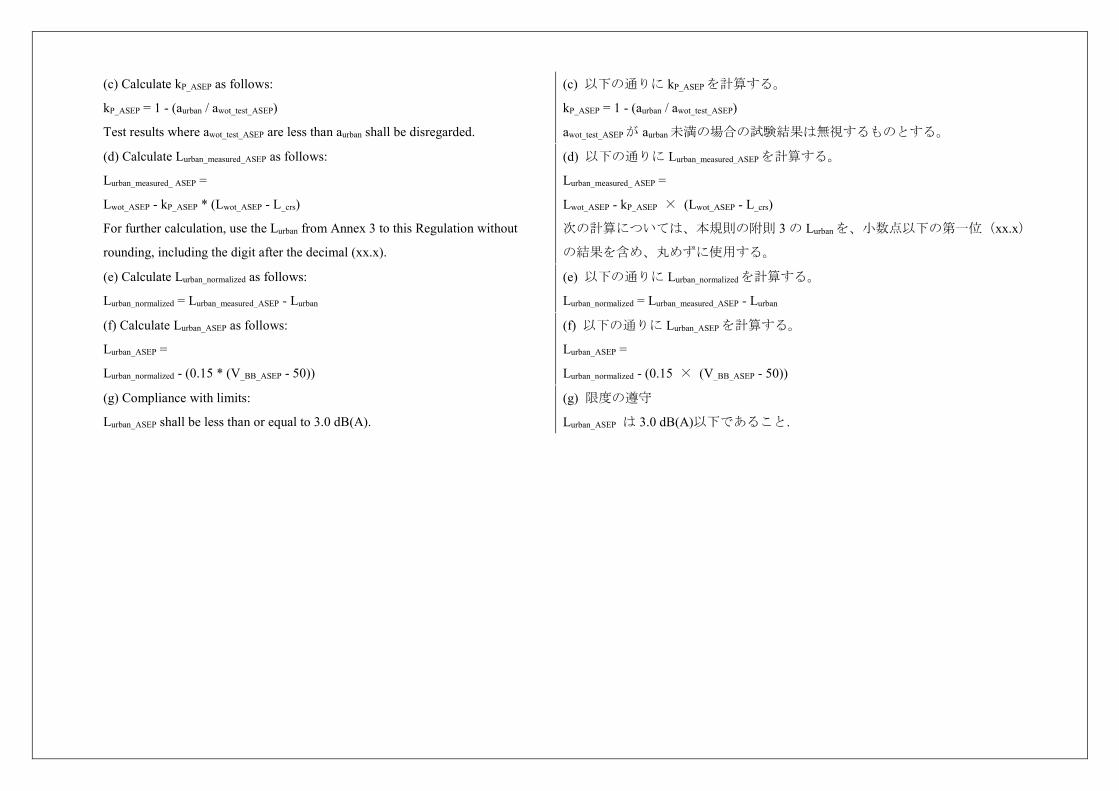
(c) Calculate kP_ASEP as follows:
kP_ASEP = 1 - (aurban / awot_test_ASEP)
Test results where awot_test_ASEP are less than aurban shall be disregarded.
(c) 以下の通りに kP_ASEP を計算する。
kP_ASEP = 1 - (aurban / awot_test_ASEP)
awot_test_ASEP が aurban 未満の場合の試験結果は無視するものとする。
(d) Calculate Lurban_measured_ASEP as follows:
Lurban_measured_ ASEP =
Lwot_ASEP - kP_ASEP * (Lwot_ASEP - L_crs)
For further calculation, use the Lurban from Annex 3 to this Regulation without
rounding, including the digit after the decimal (xx.x).
(d) 以下の通りに Lurban_measured_ASEP を計算する。
Lurban_measured_ ASEP =
Lwot_ASEP - kP_ASEP × (Lwot_ASEP - L_crs)
次の計算については、本規則の附則 3 の Lurban を、小数点以下の第一位(xx.x)
の結果を含め、丸めずに使用する。
(e) Calculate Lurban_normalized as follows:
Lurban_normalized = Lurban_measured_ASEP - Lurban
(e) 以下の通りに Lurban_normalized を計算する。
Lurban_normalized = Lurban_measured_ASEP - Lurban
(f) Calculate Lurban_ASEP as follows:
Lurban_ASEP =
Lurban_normalized - (0.15 * (V_BB_ASEP - 50))
(f) 以下の通りに Lurban_ASEP を計算する。
Lurban_ASEP =
Lurban_normalized - (0.15 × (V_BB_ASEP - 50))
(g) Compliance with limits:
Lurban_ASEP shall be less than or equal to 3.0 dB(A).
(g) 限度の遵守
Lurban_ASEP は 3.0 dB(A)以下であること.
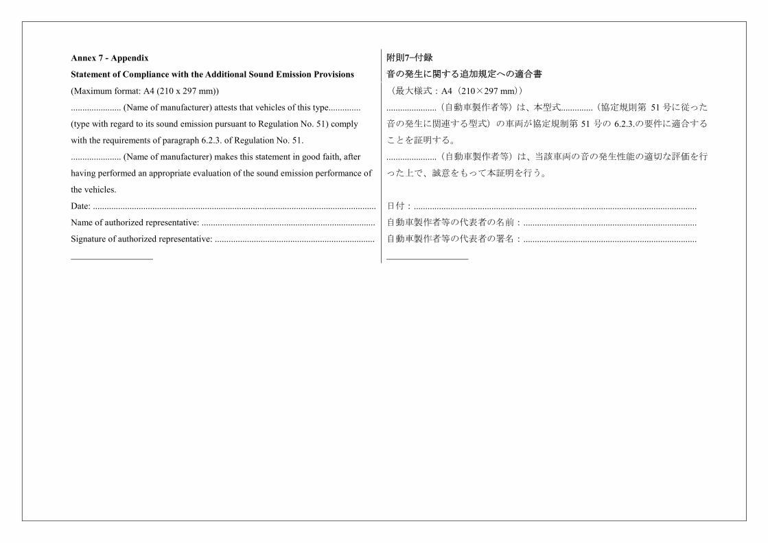
Annex 7 - Appendix
Statement of Compliance with the Additional Sound Emission Provisions
附則7−付録
音の発生に関する追加規定への適合書
(Maximum format: A4 (210 x 297 mm))
...................... (Name of manufacturer) attests that vehicles of this type..............
(type with regard to its sound emission pursuant to Regulation No. 51) comply
with the requirements of paragraph 6.2.3. of Regulation No. 51.
...................... (Name of manufacturer) makes this statement in good faith, after
having performed an appropriate evaluation of the sound emission performance of
the vehicles.
Date: ............................................................................................................................
Name of authorized representative: ............................................................................
Signature of authorized representative: ......................................................................
(最大様式:A4(210×297 mm))
......................(自動車製作者等)は、本型式..............(協定規則第 51 号に従った
音の発生に関連する型式)の車両が協定規制第 51 号の 6.2.3.の要件に適合する
ことを証明する。
......................(自動車製作者等)は、当該車両の音の発生性能の適切な評価を行
った上で、誠意をもって本証明を行う。
日付:............................................................................................................................
自動車製作者等の代表者の名前:............................................................................
自動車製作者等の代表者の署名:............................................................................


![Proposal for a new UN Regulation on uniform provisions ......I. Proposal “ UN Regulation No. [XXX]1 Proposal for a new UN Regulation on uniform provisions concerning the approval](https://img.pdfslide.net/doc/110x75/60dc68830e725752376262e0/proposal-for-a-new-un-regulation-on-uniform-provisions-i-proposal-aoe-un.jpg)


![DRAFT UN Regulation No. [X] Uniform provisions concerning](https://img.pdfslide.net/doc/110x75/626929d1b823ea2d9e2cb657/draft-un-regulation-no-x-uniform-provisions-concerning-.jpg)