Embed Size (px)
Citation preview
--~ ~ -'!'
~ 1
n
,i. è,
".
fr;~-
('
I :._-~ i~.:.,~I Masonellan~~i~~1 ."..",c," "~7':",
:-"~ ..
, ,'. .iti:~h . " \
Generai::,..":::,,;
These installation, operation, adjustment and mainte- local Masoneilan Representative or Spare Parts rJnance instructions, apply to the Masoneilan Models Department. When ordering parts, always include Model "-535HI 536H Reducing and Back Pressure Regulators and Serial Numbers shown on serial plate.and Models 535H-501 536H-50 Differential PressureRegulators. They include a parts reference list including After sales Departmentrecommended spara parts (see page 5). Masoneilan has a highly skilled After Sales Department
Refer to Instructions No 176420 E far connecting, available far star1-Up, maintenance and repair of ouradjustment and maintenance of the 10900 Series regulators and components parts. Contact the nearestActuators equipping the 500 Series regulators. Masoneilan Sales Office or Representative or, directly
Description-Operation hNos 535H/536H Regulators Nos 535H-50/536H-50 RegulatorsThe 535H direct operated regulators are designed to Masoneilan 535H-501 536H.50 Series Differentialregulate the discharge pressure of steam driven pumps Pressure Regulators ara designed far maintaining oneand to maintain a uniform reduced pressure on such pressure in excess of another (reference) pressure byindustriai equipment as gas distribution systems, fluids an adjustable amount.heat exchangers, reboilers, fractionning columns and on .. .. . .fuellines to gas-fired boilers, topping units and prehea- TYPICaI appllCatlOn~ Include regulatlng the del~very pres-terso AIso supplied far back-pressure service Is' the 536 sure of a steam-dnven pump at a predetermlned va!ueH Model. Bodies of regulators ara offered in single seat abo~e a refe~ence pressure; and f.or compressor bearlngtype seallng servlce, where the seallng pressure must be. maintained at a desired value above casing pressure.
Operatlon Operatlon .The adjustable spring cf actuator is set far the desired Th ad. stabl . f ct t is t f th d .Ired. e Ju e sprlng o a ua or se or e escontrolled pressure. In No 535H regulators thls sprlng d.ff t. 1 I N 535H 50 I t th.sI Gran la pressure. n o - regu a ors Iholds the regulator open; In No 536H regulators the . h Id th I t .. N 536H 50 I - .spring holds the regulator closed. An Increase in control- spnng o ~ e regu a or open, In o : regu ~led pressure above the set point causes No 535H regu- to:rs the ~pnng holds the reg.ulator closed. An Increase Inlators to cIose or No 536H r ulators to o n. differentlal above the set polnt causes No 535H.50 regu-
eg pe lators to close or No 536H-50 regulators' to open.Variations In the controlled pressure thus cause the .. . .necessary regulator movement to resto re the controlled Variatlons In the differenti al pressure thus cause the
U t t . t necessary regulator movement to restare the controlledpress re o se poln. .pressure to set polnt.
InstallationBefore Installing, blow out line thoroughly to remove ali diaphragm chamber down so that the diaphragm will beforeign matter which might foul thé regulator. protected by a water seal. " installed otherwise, an ade- )'~_;é :;
quale water seal or seals must be provided. fi:f1:~~'Placa the regula.tor vorticaJJy in. a horizontal run of pipo 1j';.~~~~~so that the rontrolled fluid will fk>w through the body in A three valve by-pass around the regulators permits fC!;~{#;~'the dlrection Indicated by the arrow on the body or the removing the regulator tram the li ne without shutting off ""'::~~.':words -IN & our marked on the connections. On the flow. "éj)f!ii,';:;~steam servk:e, the regulat.or soould be installed with the ,.',~(~'-,
., ..
, --
J~C'.~-~" --c-c---~-~ ~
,~
~ ...
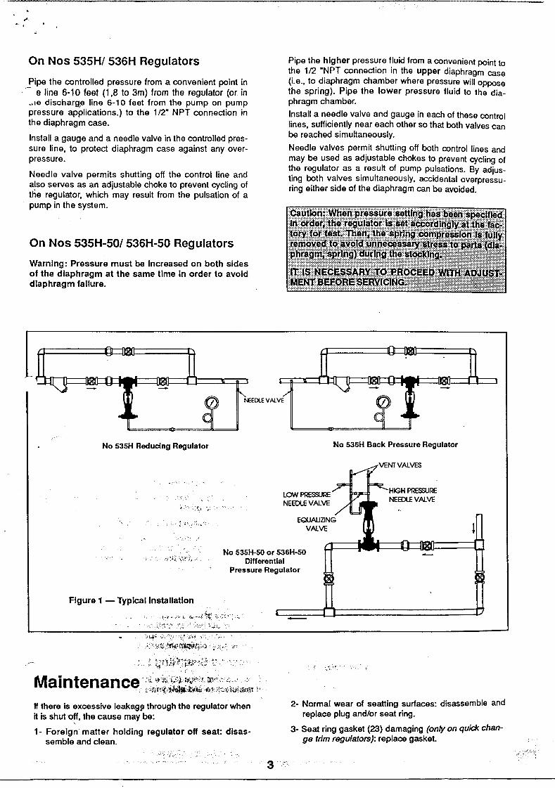
On Nos 535H/ 536H Regulators Pipe the hlgher pressure fluid from a convenient point tothe 1/2 wNPT connection in the upper diaphragm case
Pipe the controlled pressure from a convenient point in (i.e.. to diaphragm chamber where pressure will oppose~ e line 6-10 teet (1,8 ta 3m) trom the regulator (or in the spring). Pipe the lower pressure fluid to the dia-
..Ie discharg,e line 6-10 feet tram the pump on pump phragm chamber.pressure applications.) to the 1/2w NPT connection in Install a needle valve and gauge in each of these contraithe diaphragm case. lines, sufficiently near each other so that both valves canInstall a gauge and a needle valve in the controlled pres- be reached simuftaneously.sure li ne, to protect diaphragm case against any over- Needle valves permit shutting off both controllines andpressure. may be used as adjustable chokes to prevent cycling of
" , the regulator as a resuft of pump pulsations. By adjus-Needle valve permlts shuttmg off the contrai Iine and ting both valves simultaneously accl'
dent II d ' bl h k l ' f ' a overpressu-
a,so serves as an a Justa e c o e to prevent cyc Ing o ring either side of the diaphragm can be 'd dthe regulator, which may result tram the pulsation of a avo I e .
- --NEE[x'E V AL VE
No 535H Reduclng Regulator No 536H Back Pressure Regulator
lOW ~~NEEDlE V Al VE
EQUAUZJNG
VAlVE
No 535H-SO or 536H-SO -Dlfferentlal
Pressure Regulator
Figure 1 - Typlcallnstallatlon
~.j",.:,.;.o;",I,~;,;;::"" -
'~~:;:"'-,:.;!r;i:...,:~~ 'o..,c"""no:c~~' ,,,:""'c :!i,:"'Oy;""'c"1!;:~~"""""""~ .
M a I n te n a n ce i':Jr\,(,j:I.~it.~,,~;,;4?~'\iJ,t,;,.-r:ì\!è
If there is excessive leakag~ throughthe regulatorwhen 2- Normal wear of seatting ~urfaces: disassemble andit is shutQff, the cause may be: replace plug and/or seat rmg.1- Foreig~ matter holding regulator off seat: disas- 3- Seat ~ing gasket (23) damaging (on/y on quid< chan-
semble and clean. g8 tnm regulators): replace gasket.
3

--~-
,;
Body SIA disassembly . Remove plug (3) and plug stem (4) tram the bonnet (6).
: ~:d "(ì
Nos 535H and 535H 50 Regulators service damage. After determining the maintenancerequired, praceed to the appropriata section ot this ins-
Threaded Trlm (Figure 2) truction book.
. Disconned the controlline(s) at the diaphragm case. Nos 536H and 536H 50 Regulators Io Remove body stud nuts (15).. . Qulck-Change Trlm (Figure 4)
o Fasten the aduator to a holstlng gear and, very slowly,pull out aduator, bonnet (6), plug (3) and plug stem . Disconnect the contraI line(s) at the diaphragm casetram the body. and conned a temporary supply air line.Note: "a new body gasket (16) is not available, care o Apply on the diaphragm sufficient pressure to open the .must be taken to preserve the old gasket for re-use. plug about 1 mm.SpiraI wound flexitallic gaskets are standard in the535H d 535H 50 d . nd n. . ded o Loosen stem locknuts (13), turn them down plug steman - eslgn a IS recommen .th t k t J tal"ed h ti. th la, and Iod< them together. With wrench applled aver Iock-
a a new gas e Utt InS , eac me e regu ,oris disassembled. nuts, !urn plug stem out ot actuator sterno
o Loosen stem Iod<nuts (13), turn them down plug stem . Shut off air pressure. and disconnect air lines at theand Iock them together. With wrench applied aver Iock- actuator. Unscrew drlve nut (7) and remove actuatornuts, turn plug stem out ot actuator sterno tram the bonnet (6).
J. Remove drive nut (7) and detach actuator yoke tram . Remove body stud nuts (15) and remove together bon-the bonnet (6) net (6) cage (22), seat ring (2) plug (3) and stem (4). as one unito Remove the seat ring gasket (23) tram the. Loosen stem locknuts (13) and remove them tram the body.plug sterno
° . Note: If new gaskets (16 & 23) 'are not available, care. Remove p~lng tlange stud nuts (10), packlng tlange musi be taken to preserve the old gaskets for re-use.
(9) and pad<lng tollower (8) tram the plug sterno SpiraI wound flexitallic gaskets are standard in the ~. Remove plug (3) and plug stem (4) tram the bonnet (6). 536H and 536H-50 design and it is recommendedCautlon: Care musi be taken lo avoid damage to the tha~ a ~ew gaskets are installed each rime the regula-plug and plug guide. lor IS dlsassembled.
. Remove old packing (11) and packing spacer (12) tram . Loosen stem k>cknuts (13) and remove them tram thethe bonnet (6). plug stem (4).. Bonnet (6), plug (3), bushing (17) and seat ring (2) may . Remove pa~ing flange stud nuts (10), pad<ing flangenow be inspected far wear and service damage. Atter (9) and packlng tollower (8).deterrnining the maintenance required, proceed to the . Remove plug (3), plug stem (4), cage (22) and seatappropriate sedion ot these instructions. ring (2) tram the bonnet (6).
Qulck-Change Trlm (Figure 3) Caul/on: Care must be taken to avoid damage to the. Disconned ~e controlline(s) at the diaphragm case. plug and plug guide.. Unscrew drive nut (7) tram the bonnet (6). . Remove old packing (11) and paking spacer (12). -. Loosen stem Iod<nuts (13), tum them down plug stem . Ali components may now be inspected far wear and
and Iock them together. With wrench applied aver Iock- service damage. After determlning the maintenancenuts, tum plug stem out ot actuator sterno required, proceed to the apprapriate section ot this ins- .
truction book.. Remove actuator tram the bonnet.
. Loosen stem \ocknuts (13) and remove them tram theplug sterno Remove body stud nuts (15). Repair .
. Remove bonnet (6), plug stem (4) and plug (3) as one Th t th O d o . t . t . t ru it e purpose o IS se IOn IS o asSIS maln enance pe -n . sonnel by suggesting methods ot component mainte-. Since the cage (22), seat ring (2) and seat ring gasket nance which is largely dependent on the tools and
(23) afe held in piace by.the bonnet, they may now be machine shop equipment available.removed.Note: If new gaskets (16 & 23) Me noi avallable, care Threaded Seat Ring Removal (Figure 2) ~musi be taken lo preserve the old gaskets for re-use. Threaded seat rings (2) afe installed tightly at the pointSpIraI wotJnd flexitallic gaskets Me standard In the of manufacture and atter years ot service, they afe otten535H and 535H-50 deslgn and it Is recommended difficult to remove. To facilitate removal, seat rlngthat a new gsskets Me /nsta//ed eacl! lime the rsgula- wrenches can be tabricated to engage the seat ring lugsf tor is disassembled. . and adapted to a shod< wrench. If th.e ring Js exceptio- I
~ . Remave packing tlange stud nuts (10), pad<ing flange nally re~lsta~t to removal, the appllcation ot heat or(9) and pad<ing tollower (8). penetratlng 011 should be helptul.
~7~ ~;""'"""""',;I ..~ ,'c,, 'è 4 .
I.~~= _._~
L"C .:, .
134
217
101 2
91
6 8 3
14
215
16 5 2
. 17
Figure 33
Qulck Change Trlm2 Model 535H or 535H-50
Regulator1 (Detall>
Figure 2 134
Threaded TrlmModel 535H or 535H-50 7
Regulator 1 10
91
6
1
1
3
Figure 4
Qulck Change TrlmModel 536H or 536H-SO
Regulator 1
'*l$:'
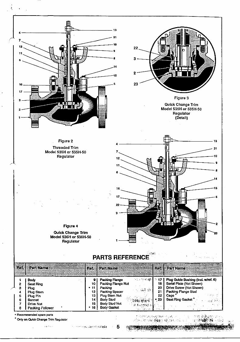
PARTS REFERENCE"'-'
1 Body 9 Packing Flange Plug Guide Bushing (Incl. w/ref.. 6)2 Seat Ring 10 Packing Flange Nut Seria! Plate (Not Shown)3 Plug . 11 Packing Drive Sa'ew (Not Shown)4 Plug Stem 12 Packing Spaoor Packing Range Stud5 Plug Pin 13 Plug Stem Nut Cage.6 Bonnet 14 8ody Stud Seat Ring Gasket .7 Drive Nut 15 8ody Stud Nut8 Paoong Follower - . 16 Body Ga&ket
. Rerommended spare parta. 0nIy OrI Q.lid< Change Trim Regulator
,,' 5
.
~
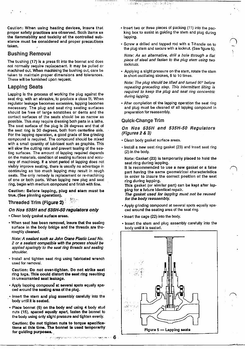
Cautlon: When uslng heatlng devlces, Insure that o Insert two or three pieces of packing (11) into the pac-pro per safety practlces ara observed. Such Items as king box to assist in guiding the stem and plug duringthe flammabl/lty and toxlclty of the controlled sub- lapping.stance must ba consldered and proper precautlons S d ' Il d d t d d 'ìth T h di r,taken o crew a rl e an appe ro w a - an e on to "'.. , the plug stem and secure with a /ocknut. (See figure 5). .
Bushing Remaval Note: A5 an alternative, drill a hole through a tlat I
The bushing (17) is a press fit into the bonnet and does pi9Ce ot 5teel and fasten to the plug stem u5ing twonot normally raquire replacement. It may be pulled or locknuts.machined out. When machlning the bushing out, care be o Applying a slight pressure on the stem, rotate the stemtaken to maintain proper dimensions and tolerances. in short oscillating strokes, 8 to 10 times,These will be fumlshed upon request.
Note: The plug 5hould be lifted and tumed 90° betoreLapping Seats repeating pr9Ceding step. This intermittent lifting is
. . . , required to keep the plug and seat ring concentricLappl~g IS t,he process.of worklng the plug ag~lnst the during lapping. .seat nng, wìth an abrasIVe, to produce a close filo Whenregulator leakage becomes excessive, lapping becomes o After completion of the lapping operation the seat ringnecessary, The plug and seat ring seating surfaces and plug must be cleaned of alliapping compound inshould be free of large scratches or dents and the preparation for reassembly.contact surfaces of the seats should be as narrow aspossible. This may require dressing both parts in a lathe. aulck-Change TrlmThe seat ~urf~ce of the plug is 28 degrees an? that.cf O Nos 535H and 535H-50 Regulat rthe seat nng IS 30 degrees, both tram centerllne axlS. n o SFor the lapping operation, a good grade of fine grinding (Flgures 2& 3)
compound is required. The compound should be mixed o Clean body gasket surface areas.with a small quantity of lubricant such as graphite. This '"will slow the cutting rate and prevent tearing of the sea- o Inst,a" a new seat rmg gasket (23) and Insert seat rlngting surfaces. The amount of lapping required depends (2) In the body.
on the materials, condition of seating surfaces and accu- Note: Gasket (23) Is temporarl/y placed to hold ther~<:y of. machining. ~ a 'short ~eriod of lapping does n?t seat rlng durlng lapplng.vlslbly Improve seating, there IS usually no advantage In It Is recommended to use a new gasket or a false ()continuing as too much lapping may result in rough part havlng the same geometrlcal characterlstlcsseats. The only remedy is replacement or re-machining In order to 1nsure the correct posltlon of the seatof one or both parts. When lapping new plug and seat rlng durlng lapplng.ring, begin with medium compound and finish with fine. Thls gasket (or slmllar part) can be kept after lap-
Cautlon: Before lapplng, plug anci stem must be plng for a future Identlcal repalr.true. (See plnnlng operation). The gasket used for lapplng must not be reused
for the body reassembly.Threaded Trlm (Figure 2) . .. . o Apply grlndlng compound at several spots equally spa-On Nos 535H and 535H-50 regulators only ced around the seating area of the seat fingo
o Clean body gasket surface ar~as. o Insert the cage (22) into the body.
. When seat has been removed, Insure that the sealing o Insert the stem and plug assembly carefully into the
surface in the body bridge and the threads ,are tho- body unti! it is seated.roughly cleaned.
Note: A sea/ant such as John Crane Plasti<: Lead No. i::~;;::
2 or a sealant compatib/e with the process should be 1ili:applied sparingly to the seat ring threads and sealing :~:: .shoulder. :.,:-:.
o Install and tighten seat ring using fabricated wrenchused far remava!.
Cautlon: Do not over-tlghten. Do not strlke seatrlng lugs. Thls could dlstort the seat rlng resultlngIn unwarranted seat leakage.
o Apply lapping compounà at several spots equally spa-ced around the seating area of the plug.
.' Insert the stem and plug assembly carefully into the ~body unti! it is seated.. Piace bonnet (6) on the body and uslng 4 body stud '
nuts (15), spaced equally apart, fasten the bonnet tothe body using only slight pressure and tighten evenly.
Cautlon: Do not tlghten nuts to torque speclflca-tlons at thls tI me. The bonnet la used temporarl/y A 5 La I tfar guldlng purpoaea. , gure - pp ng sea s
'." 6. ~-
. ~,.,-~~.
~
.. .
. Piace bonnet (6) on the body. . Insert two ~r ~hree.P!eces of packing into the packingC ti . 1 th t th t I (2) (22) box to asslst m guldlng the stem and plug during lap-
- au on. nsure a e sea r ng , cage, in( and bonnat (6) are properly allgned. p g.
. , . Screw a drilled and tapped !Od with a T -handle on to the. Uslng 4 OOdy stud nuts (15), spaced equally apart, fas- pI st and ith 1 J,- ut.(S ti )" ug em securew a~1 ee ~ure5ten the bonnet to the body usmg only sllght pressure .
and tighten evenly. Note: As an alternative, dri// a ho/e through a f/atCa ti Do t ti ht t t t Ifl piece of stee/ and fasten to the p/ug stem using twou on : no 9 en nu s o orque spec ca- bcknutstlons, at thls tlrne. The bonnet Is used ten:lporarlly .far guldlng purposes. . While to exert a lightly pulling on the stem, rotate it inI rt tw th ' f cki , t th ki short oscillating strokes 8 to 10 times,. nse o or ree pleces o pa ng m o e pac ngbox to assist in guiding the stem and plug during lap- Note: The p/ug should be pu//ed out and turned 90°ping. before repeating preceding step. This intermittent pu/-Scr d '1'-..1and t,,~ rod ith T' " andle to th /ing is required to keep the pIug and seat ring concen-. ewa n ~ ,., w a "Il on e tr' d . lap'plug stem and secure with a bd<nut. (See f~ure 5). IC unng plng.
. , . Atter completing the lapping operation, the seat ring. N.ote: As an alternative, dnl/ a ho/e throug~ a f/at and plug must be cleaned of ali lapping compound inplec8 of stee/ and fastento the pIug siero uslng two preparation far reassembly,Iocknuts.
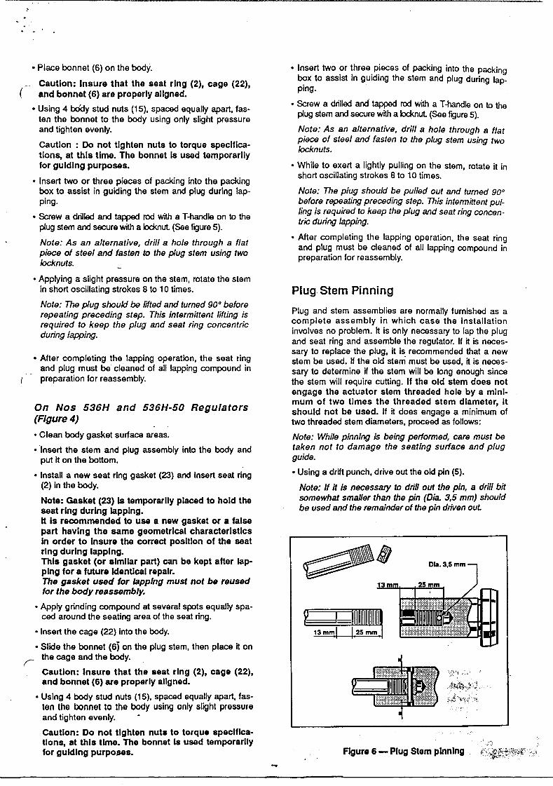
. Apptying a slight pressure on the stern, rotate the stemin short oscillating strokes 8 to 10 times. Plug Stem Pinning
Note: The pIug should be /ifted and turned 90° before "
repeating preceding step. This intermittent lifting is Plug and stem assem~lles a:e normalty fu~lshed a~ arequired to keep the p/ug and seat ring concentric complete assembly In whlch case the Installatlonduring /apping involves no problem. It is only necessary to lap the plug. and seat ring and assemble the regulator, If it is neces-
, . , , sary to replace the plug, it is recommended that a new. Atter completlng the lappmg operatlOn, the seat rmg stem be used. If the old stem must be used it is neces-and plu~ musi be cleaned of ali lapping compound in sary to determina jf the stem will ha long e~ough since
I preparatlon far reassembty. the stem will require cutting. If the old stem does noIengage the actuator stem threaded hole by a mlnl-mum of two tlmes the threaded stem dlameter, It
On Nos 536H and 536H-50 Regulators should noI be used. If it does engage a minimum of(Figure 4) two threaded stem diameters, proceed as follows:. Clean body gasket surface areas. Note: While pinning is being performed, care musi be
. Insert the stem and plug assembly into the body and ta~en noi to damage the seating surface and p/ugput it on the bottom. guide.. Install a new seat ring gasket (23) and Insert seat ring . Using a drift punch, drive out the old pin (5).
(2) in the body. Note: Il it is necessary to drifl out the pin, a drill bitNote: Gasket (23) Is temporarlly placed to hold the somewhat smal/er than the pin (Dia. 3,5 rom) shou/dseat rlng durlng lapplng. be ussd and the remainder of the pin driven outIt Is recommanded to use a new gasket or a false. part havlng the same geometrlcal characterlstlcs
In order to Insure the correct posltlon of the seatrlng durlng lapplng. ~;;;~~~ ~~ liliJThls gasket (or slmllar part) can be kept after lap- :::;;--- ~\\\~ flI!I Dia, 3,5 mmplng far a future Identlcal repalr. ~The gasket used for /apping musI noI be reusedfor Ihe body reassembly.
. Appty grinding com~und at several spots equally spa-
g~3!!ced around the seating area of the seat fingo = I 1III. Insert the cage (22) into the body. 13 mm 25 mm
. Slide the bonnet (6) on the plug stem, then piace it on
r the cage and the body.
Cautlon: Insure that the seat rlng (2), cage (22),and bonnet (6) ara properly allgned.
. Using 4 body stud nuts (15), spaced equally apart, fas-ten the oonnet to the body using only slight pressureand tighten eventy. -
Cautlon: Do not tlghten nuta to torque speclflca-tlons, at thls tlme. The bonnet Is used temporarllyfar guldlng purpo~s. Figure 6 - Plug Stem plnnlng
...

~ ~---~ ,
-- ,
. Unscrew the plug from the sterno (Counterclockwise.) Addlng Packlngs
. Cut off the stem directly above the pin hole (Figure 6). To add a ring of packing, depressurize the regulator,
. Re-thread the stem the originai amount. back off packing flange nuts (10) ali the way, lift the pac- ~ nking flange and follower and insert one ring of packing. "-"'
Note: The apea of the plug siero marked 13 mm in TIghten nuts (10) finger tight plus one full turnofigure 6 se/Ves as a guide and musi be checked toinsure a close fit in the regulator plug. Body SIA Reassembly
. Screw the stem solldly into the plug.
. Piace the plug guide on a V-block and using a 3,5 mm After completion of the required maintenance the regula-size drill bit, drill the stem using the hole in the plug as tor should be re-assembled using the following proce- .a guide. dures:
. Remove any burrs from the plug guide by making a Note: If any of the following steps were completed .slight counterbore. during maintenance, proceed to the next step.
. Select the correct size pin, apply a small amount of On 535 H and 535H-50 Regulatorsgrease on it, and press into the hole.
Note: The pin musi be recessed approximate/y 1116" Threaded Trim (Figure 2)(1,5mm) belo w the plug guide surface. . Clean ali gasketed surfaces.
. After the plug has been pinned, it should be placed in . Apply a small amount of sealant to the seat ringa lathe to insure it is running "true". If it is not, strike threads and sealing shoulder and installothe plug with a soft faced mallet to straighten. N A l h J h C PI ' L d AI ore: sea ani suc as o n rane ast/C ea IYO.Note: The siero should be placed in a co//et with the 2 is recommended or a sealant compatible with theplug guide against it and the plug should be struck. processo
P k. B (F . 2 & 4) . Using seat ring wrench fabricated far removal, tighten ")ac Ing OX Igures seat ring only enough to insure a seal.
Packlng Replacement Cautlon: Do not overtighten. Do not strlke seatrlng lugs. Thls could dlstort the seat rlng resultlng
Packing box maintenance is one of the principle chores In unwarranted seat leakage.of routine se:vicing. 1ight~ess of the pac~ing. is m~intai- Note: Regulator should be lapped before final assem-ned by packlng compresslon. Compresslon IS achleved bl S "L' t- Th aded tr.m-by evenly tightening the packing flange nuts (10) against r. ee applng sea re I.
the packing flange (9). . Carefully install plug and stem assembly.
Care must be taken not to aver tighten as this could pre- . Install body gasket (16).v~nt .smooth operation of the regulator. If ali com.pre~- . Install bonnet (6) and screw body stud nuts (15).ston .IS used ,up and the regulator leaks, new packlng IS Bonnet must be positioned so the packing flangerequlred. studs afe at a right angle 70 the flow center fine.
Cautlon: Regulator must be lsolated an the pressure TIghten nuts (15). .vented before performlng packlng box malntenance. Cautlon: Refer to figure 7 far proper bolt torque
Proceed as follows : and tlghtenlng sequence speclflcatlons.. Loosen and remove packing flange nuts (10). . Insert four packing rings (11), then packing spacer (12) -. Raise pad<ing flange (2), and packing follower(15) up and two rings.
the regulator sterno . Install packing follower (8) and packin,9 flange (9).
Note: They may be taped in pIace to keep them out ofthe way before proceeding.
. Remove pad<ing (11).
. . REQUIRED TORQUE:. Install four packlng nng~(11), then spacer (12) and two
packing rings. Min.: 30 Ft. Lbs. Replace pad<ing follower (8) and packing flange (9). - - 4 daN.m r"'ì. Replace and tighten packing stud nuts (10). Max.: 37 Ft. Lbs .5 daN.mCautlon: Do not overtlghten.. Put regulator back in service and tighten packing only
as much as is necessary 10 stop leaking. I
Note: In an emergency, string packing may be used Figure 7 - Torque Requlrementas a temporary repair only. lt must be replaced with and Sequence far Nuts (15) "
the COffect packing as soon as posslble.
A-- -
- . .
..' . i" -
. Install packing flange stud nuts (1 O). . Insert four packing rings (11). then packing spacer (12)
and two rings.- Cautlon: Do noI overtlghten (See paragraph
:--MPacklng Box"). . Install packing follower (8) and packing flange (9).
. Proceed lo the be~w paragraph instructions far actua- . Install packing flange stud nuts (10).
tor to body assembly and plug stem adjustment.C t I D t ti ht (S hau on: o no aver g en ee paragrap
"Packlng Box").
Qulck-Change Trlm (Flgures 2 & 3) . Proceed to the below paragraph Instructions far adua-
tor to body assembly and plug stem adjustment.. Clean ali gasketed surfaces.
. Install seat ring gasket (23) and seat ring (2).
.Install cage (22). Actuator to Body Assembly and
, . Carefully install plug and stem assembly. Plug Stem Adjustment
Note: Regulator should be lapped before fina! assem-
. bfy. 5ee -Lapping seat-Quick-Change trim-.
'Install body gasket (16). On 535 H and 535H-50 Regulat~rs
. Install bonnet (6) and screw body stud nuts (15). . Hold actuator above body SIA. Before that actuator
BQnnet musi be positioned so the packing flange stem contact the plug stem, screw the two nuts (13) lo
studs are at a righi angle to the flow center llne. the threaded end of plug stem and piace the drive nut
lighten nuts (15). (7) on the actuator yoke.
Cautlon: Care musI be taken to assure that the . While holding the plug in -Open- position, slowly pull
cage, seat and bonnet are properly allgned In the down the actuator and screw the plug stem into the
body. Refer to figure 7 far proper bolt torque and actuator stem.
tlghtenlng sequence speclflcatlons. '
Note: Thls operatlon wlll be facliltated tumlng the
.Insert four packing rings (11), then packing spacer (12) plug stem by means of a wrench applled on the
and two rings. nuts (13) tlghtened one agalnst the other.
. Install packing follower (8) and packing flange (9). Carefully avold that seatlng surface of the plug
. Install packing flange stud nuts (10). contact the seat rlng durlng the plug screwlng.
C ti D t ti ht (S h - Pulling down motlon of the actuator and plug stem
..:uck~n:B o,,~o aver g en ee paragrap screwlng musi be slmultaneously performed:
a ng ox . carry on untll the lower parI of actuator yoke
. Proceed to the belowparagraph instructions far actua- contact the bonnet (6).
Ior to body assembly and plug stem adjustment. PI th d t . th d 'n ° Screw and. ace e a ua or In e corre pos IOn.
tighten the drive nut (7).
(Fi )
. Turn plug stem into actuator stem as far as it will goo
On 536 H and 536H-SO Regulators Ig. 4. Connect the controlled pressure line(s) to diaphragm
case.. . Clean body gasket surface areas.
. . Apply slightly more pressure to diaphragm actuator. Insert the stem and plug assembly Into the body and than spring is set foro
.. put it on the bottom.
. Turn plug stem out of aduator stem until plug is sea-. Install a new seat ring gasket (23) and insert seat ring ledo
(2) in the body.
. . Relieve diaphragm pressure and turn plug stem out of
Note: Regulato.r should be.lapped befor.e fina! assem- aduator stem one fuI! turn more.
bfy. 5ee -Lapplng seat-Qulck-Change t"m-.
I Il bod k (16) . Lod< stems with Iocknuts (13).. nsta y gas et .
. Placo back in service and tighten the packing flange
. Insert the cage (22) iAto the body. nuts (10) only as much as is necessary to stop any
. Slide the bonnet (6) on the plug stem, then piace it on leakage.
1.he cage and the body.
Cautlon: Insure that the seat rlng (2), cage (22),
and bonnet (6) are properly allgned. ,".'
. Screw body stud nuts (15). Bonnet musi be positioned On 536 H and 536H-50 Regulators
so the packing flange studs are al a righi angle lo the . Hold actuator above body SIA. Before that actuator
flow center Une. Tighten nuts (15). stem contact the plug stem, screw the two nuts (13) to
Cautlon: Refer to figure 7 for pro per bolt torque the threaded end of plug stem and piace the drive nut ~",
and tlghtenlng sequence speclflcatlons. (7). on the actuator yoke. .,..
c_-

.. .-. l''''"
. ~Iowly pull down the actuator and screw the plug stern . Connect a pressure line to upper diaphragrn caseInto the actuator sterno .
Note: Thls operatlon wlll be facllltated turnlng the . Apply sufficient pressure to upper diaphragrn case to ~plug stem by means of a wrench applled on the rnove plug off seat. ,nuts (13) tlghtened one agalnst the other. "-'-
Carefully avold that seatlng surface of the plug . Turn plug stern one full turn into actuator sterno
contact the seat rlng durlng the plug screwlng. . .-Pulling down motlon of the actuator and plug stem . Screw and tlghten nuts (13) agalnst the actuator sterno
screwlng musI be slmultaneously performed: Lock by rneans of a wrench applied on the nuts.carry on unIti the lower parI of actuator yokecontact the bonnet (6). . Connect the controlled pressure line(s) to diaphragrn. Piace the actuator in the correct position. Screw and case.
tighten the drive nut (7). . . .. . Piace back In servlce and tlghten the packing flan e. Scre~ the plug stern mto the actuator stern until the nuts (10) only as much as is necessary to stop a~y
plug IS seated. leakage. "
.
I~
.
.
Masoneilan ITALY I Masoneilan~~ii ~ é- f;;,
Headquarters Via Cassa no 77, 80020 Casavatore (Napoli) . Tel. 7892111 hWorks & Atter sale service Telex: 710084 - Facsimile: (081) 7382922 - Cable: Masonica - Casavatore ";
,iO,
Sales office C.so Garibaldi 113, 20121 Milano - Tel. (02) 29.005.650 - Telex: 314231 :North Italy Facsimile: (02) 29.005.660
Ooc. Ted\niq.. MN - Condé - DESK1OP PUBLISHING. . ~j:':r i Janu.y 1991
.;:';.:;: ,::\;~;-,:::",:,;!~,,"; " .,;."'~Ir,k' """,?~",.!~,~"""","",i[c"('!i."..l,~~~.. "'ti?'": ..;c",,':' "~,.."rc,."..,. "",;~~r",,;.. 'Cc.'
- -


![AQUAFORCE FUSION 2 - arena [アリーナ]限定カラー AQUAFORCE FUSION 2 FAR-9010W / FAR-9010WJ FAR-9011M / FAR-9011MJ FAR-9502W FAR-9503M FAR-9504W FAR-9505M FSA-O9631W 限定カラー](https://img.pdfslide.net/doc/110x75/5f335f0baab05c4ca61a0079/aquaforce-fusion-2-arena-fff-eff-aquaforce-fusion-2-far-9010w.jpg)