Embed Size (px)
Citation preview
Reinforced concrete column
Introduction to column
• Columns act as vertical supports to beams and slabs, and to transmit the loads to the foundations.
• Columns are primarily compression members, although they may also have to resist bending moment transmitted by beams.
• Columns may be classified as short or slender, braced or unbraced depending on various dimensional and structural factors.
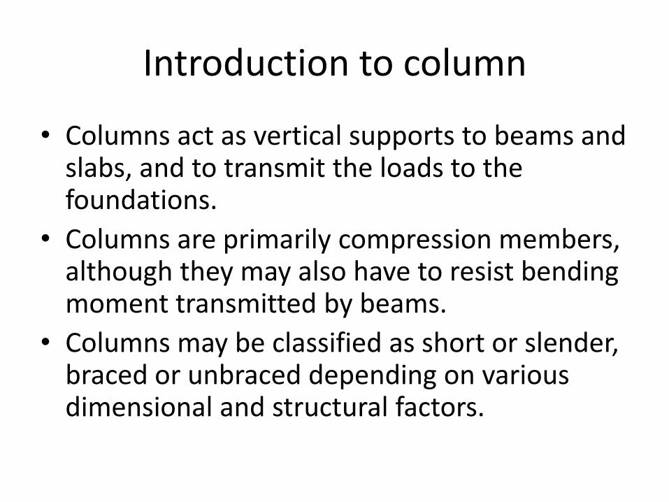
Column sections
• Common column cross sections are: (a) square, (b) circular and (c) rectangular section.
• The greatest dimension should not exceed four times its smaller dimension. (h≤4b).
• For h>4b, the member should be regarded as a wall for design purpose.
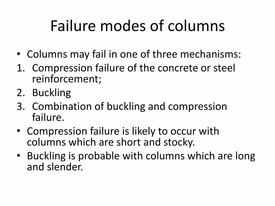
Failure modes of columns
• Columns may fail in one of three mechanisms: 1. Compression failure of the concrete or steel
reinforcement; 2. Buckling 3. Combination of buckling and compression
failure. • Compression failure is likely to occur with
columns which are short and stocky. • Buckling is probable with columns which are long
and slender.
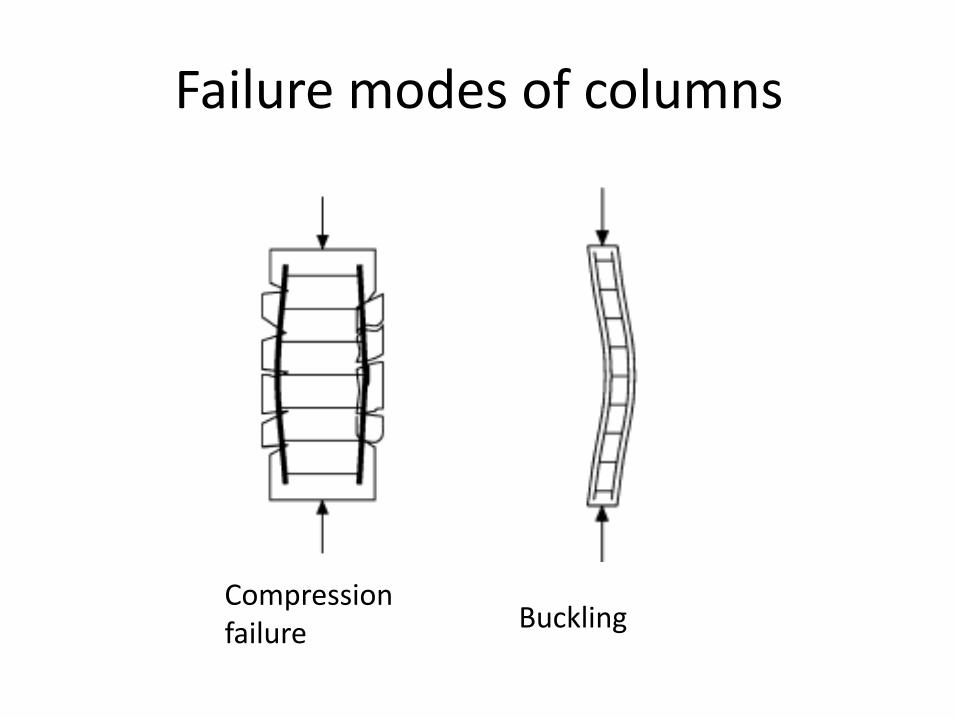
Failure modes of columns
Compression failure Buckling
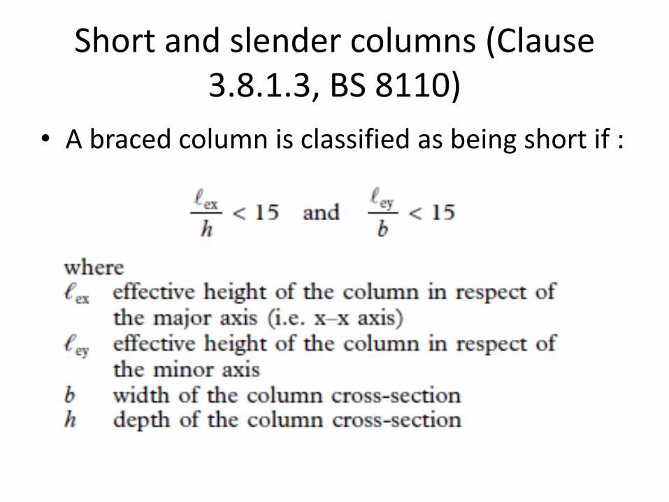
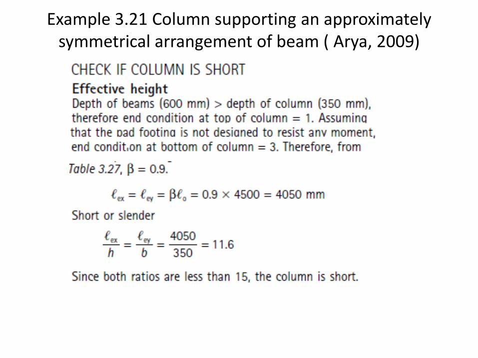
Short and slender columns (Clause 3.8.1.3, BS 8110)
• A braced column is classified as being short if :
Braced and unbraced columns (clause 3.8.1.5, BS 8110)
• A column may be considered braced in a given plane if lateral stability to the structure as a whole is provided by wall or bracing or buttressing designed to resist all lateral forces in that plane. It should otherwise be considered as unbraced.
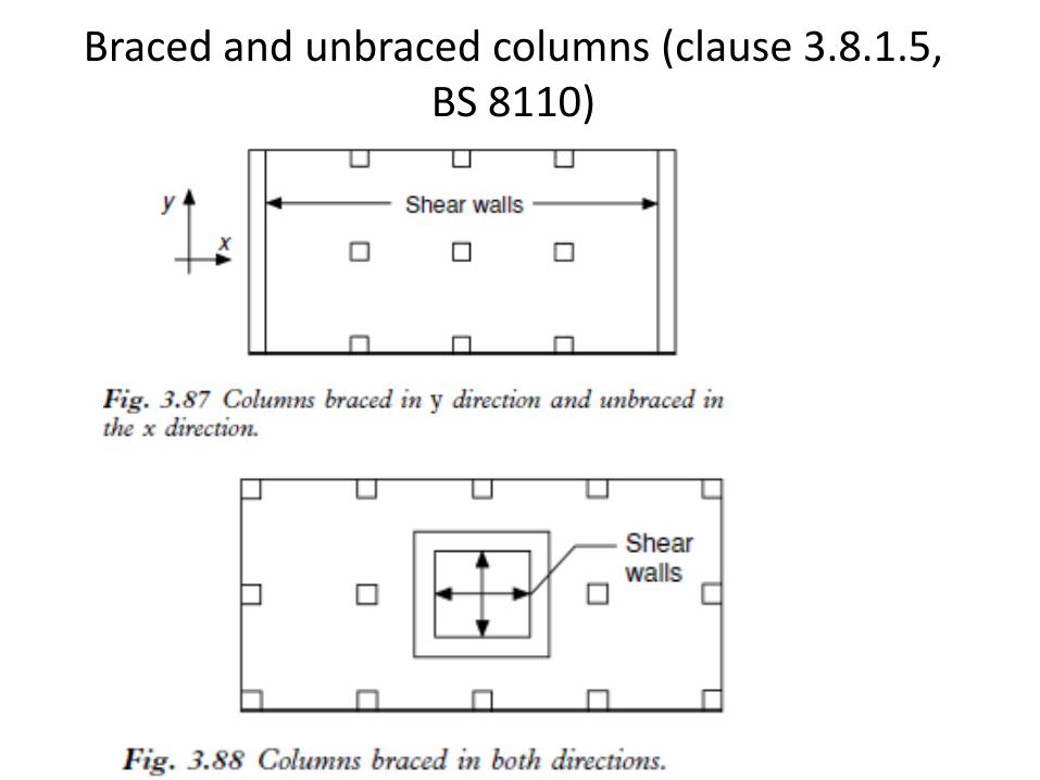
Braced and unbraced columns (clause 3.8.1.5, BS 8110)
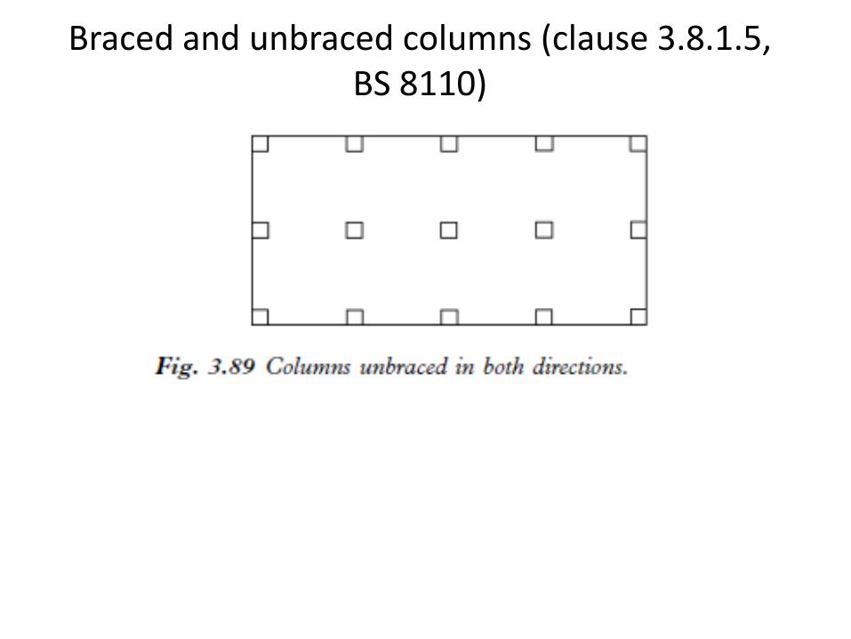
Braced and unbraced columns (clause 3.8.1.5, BS 8110)
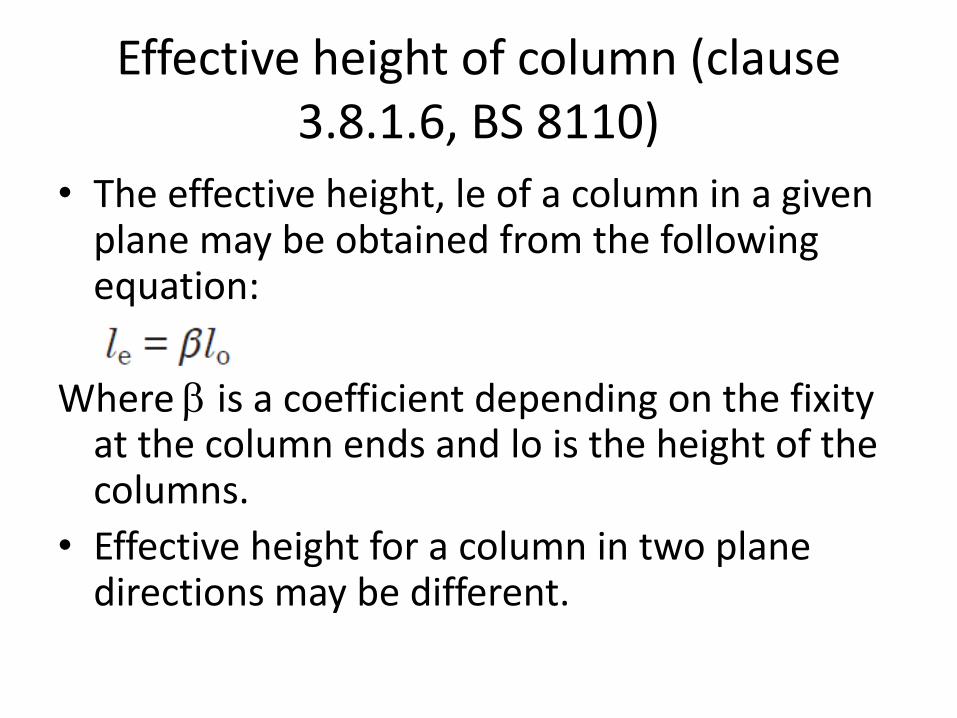
Effective height of column (clause 3.8.1.6, BS 8110)
• The effective height, le of a column in a given plane may be obtained from the following equation:
Where b is a coefficient depending on the fixity at the column ends and lo is the height of the columns.
• Effective height for a column in two plane directions may be different.
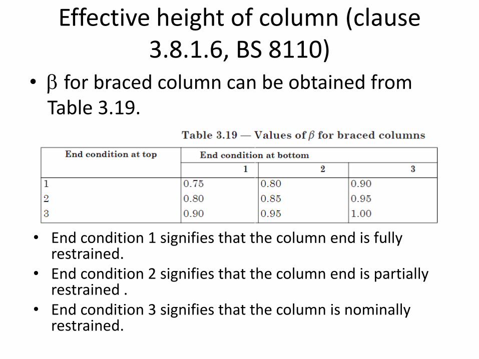
Effective height of column (clause 3.8.1.6, BS 8110)
• b for braced column can be obtained from Table 3.19.
• End condition 1 signifies that the column end is fully restrained.
• End condition 2 signifies that the column end is partially restrained .
• End condition 3 signifies that the column is nominally restrained.
End conditions (clause 3.8.1.6.2, BS 8110)
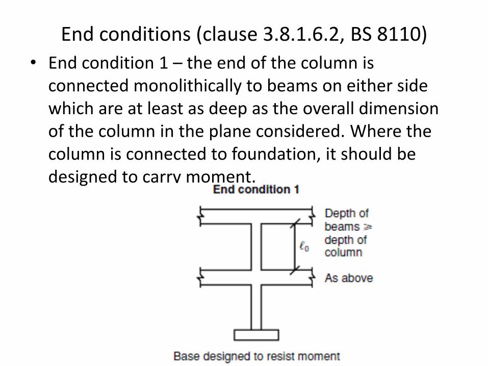
• End condition 1 – the end of the column is connected monolithically to beams on either side which are at least as deep as the overall dimension of the column in the plane considered. Where the column is connected to foundation, it should be designed to carry moment.
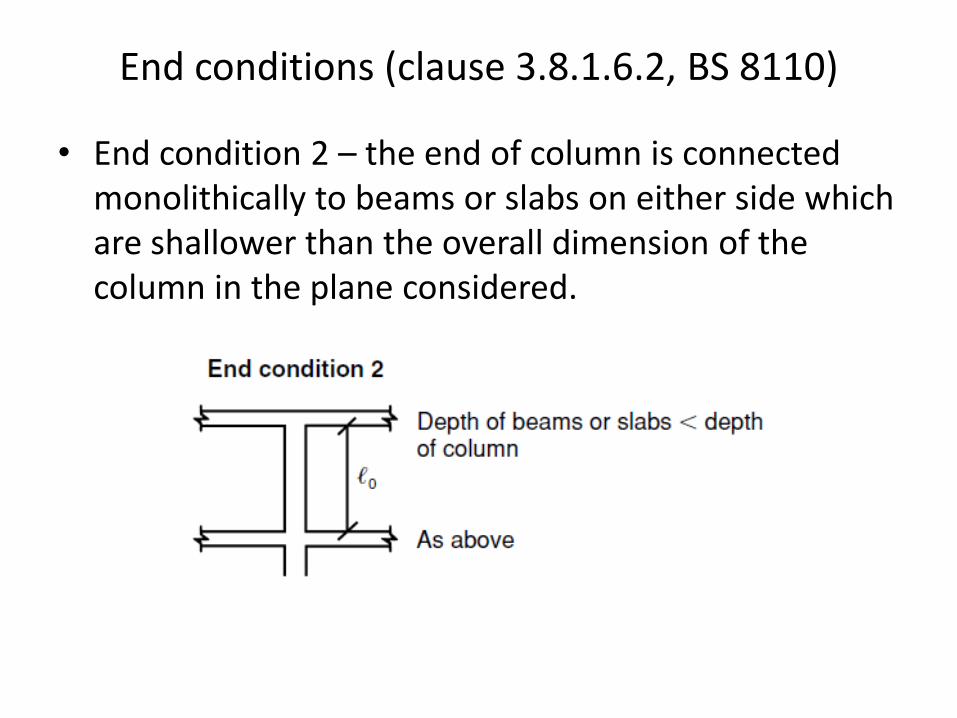
• End condition 2 – the end of column is connected monolithically to beams or slabs on either side which are shallower than the overall dimension of the column in the plane considered.
End conditions (clause 3.8.1.6.2, BS 8110)
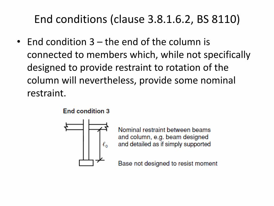
• End condition 3 – the end of the column is connected to members which, while not specifically designed to provide restraint to rotation of the column will nevertheless, provide some nominal restraint.
End conditions (clause 3.8.1.6.2, BS 8110)
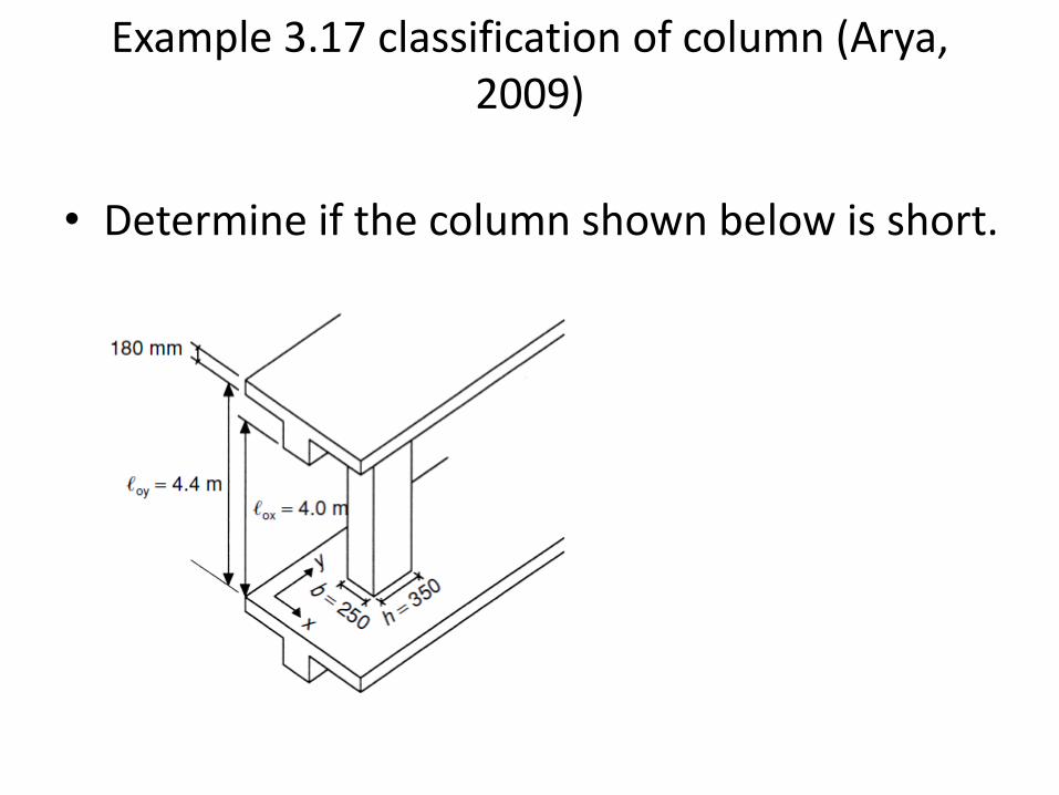
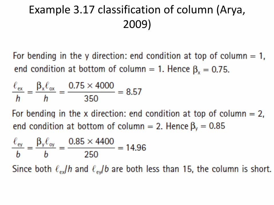
Example 3.17 classification of column (Arya, 2009)
• Determine if the column shown below is short.
Example 3.17 classification of column (Arya, 2009)
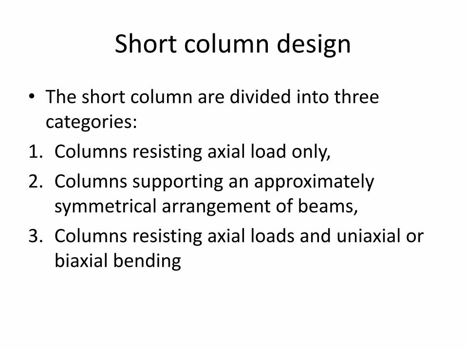
Short column design
• The short column are divided into three categories:
1. Columns resisting axial load only,
2. Columns supporting an approximately symmetrical arrangement of beams,
3. Columns resisting axial loads and uniaxial or biaxial bending
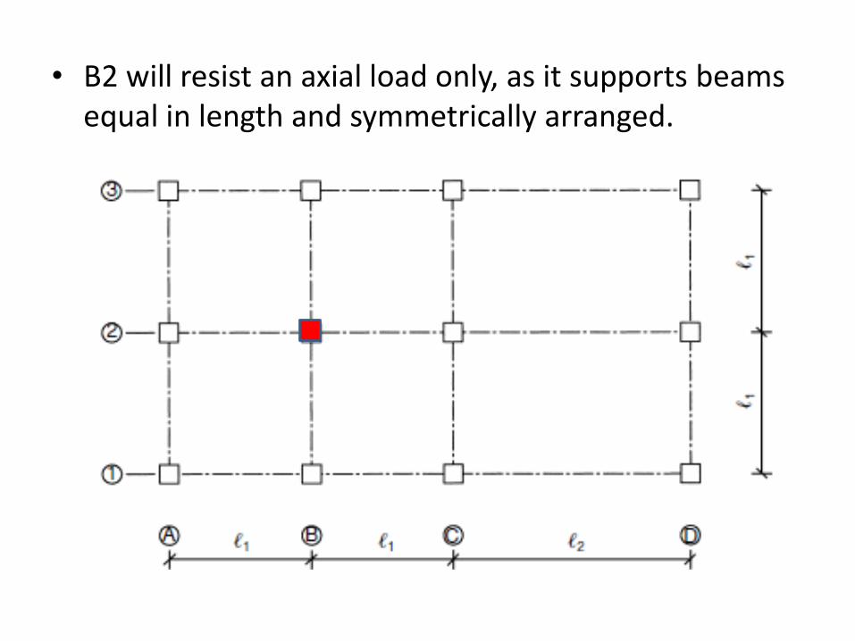
• B2 will resist an axial load only, as it supports beams equal in length and symmetrically arranged.
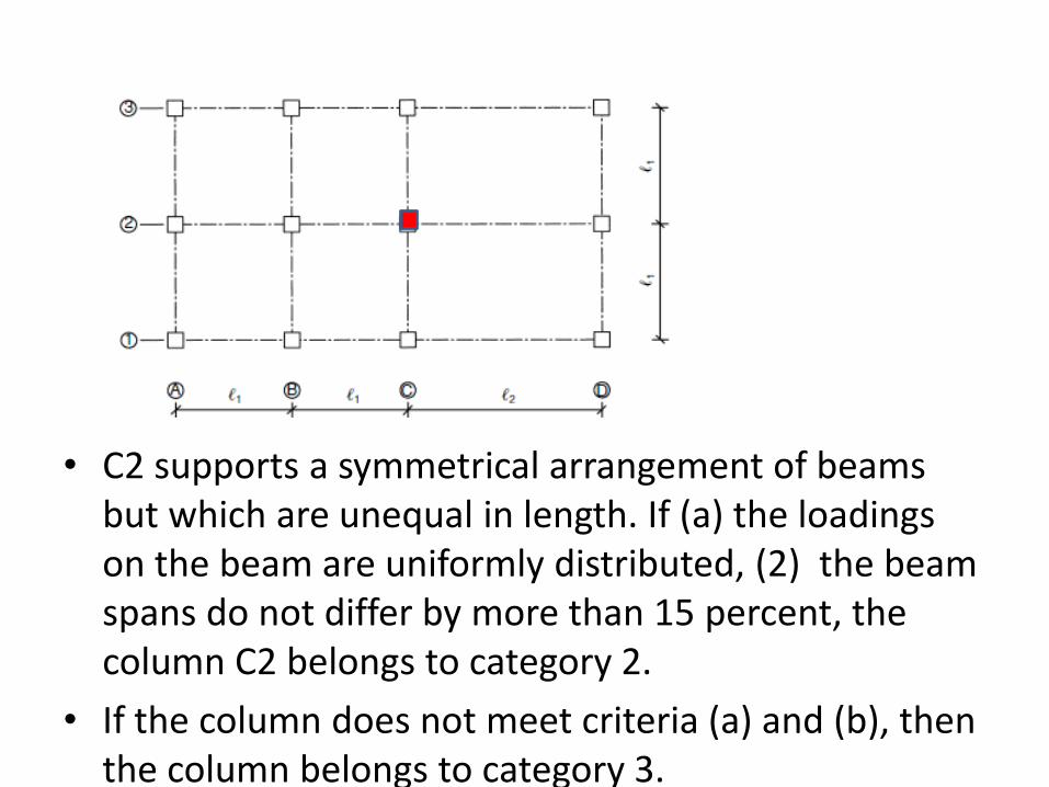
• C2 supports a symmetrical arrangement of beams but which are unequal in length. If (a) the loadings on the beam are uniformly distributed, (2) the beam spans do not differ by more than 15 percent, the column C2 belongs to category 2.
• If the column does not meet criteria (a) and (b), then the column belongs to category 3.
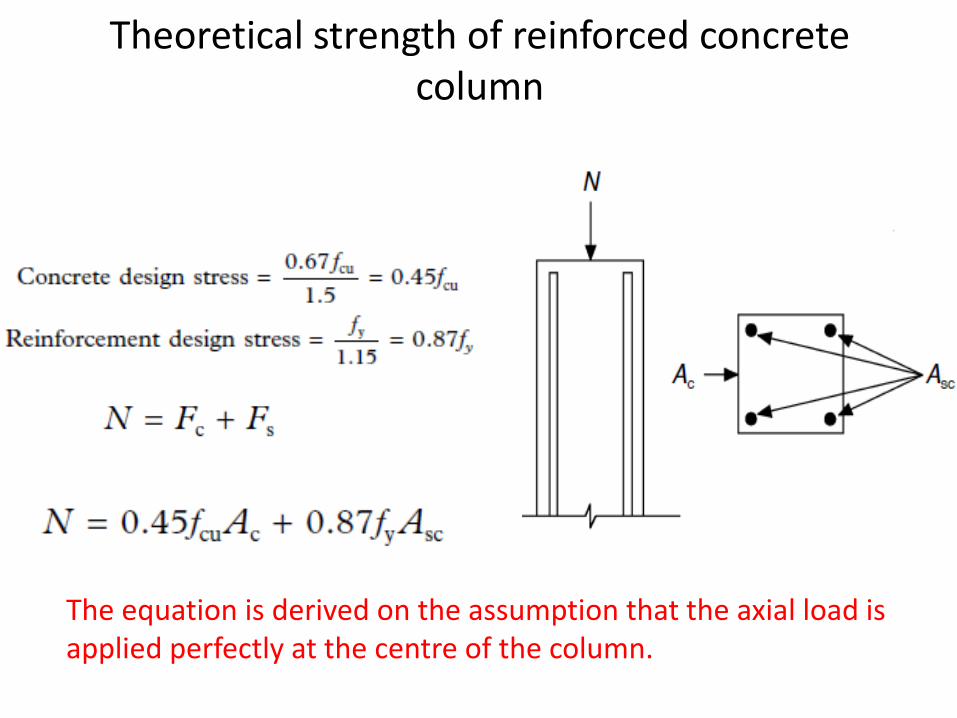
Theoretical strength of reinforced concrete column
The equation is derived on the assumption that the axial load is applied perfectly at the centre of the column.
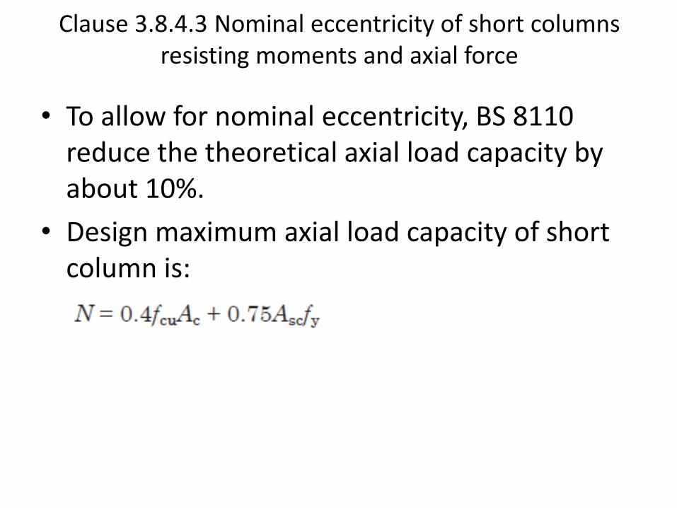
Clause 3.8.4.3 Nominal eccentricity of short columns resisting moments and axial force
• To allow for nominal eccentricity, BS 8110 reduce the theoretical axial load capacity by about 10%.
• Design maximum axial load capacity of short column is:
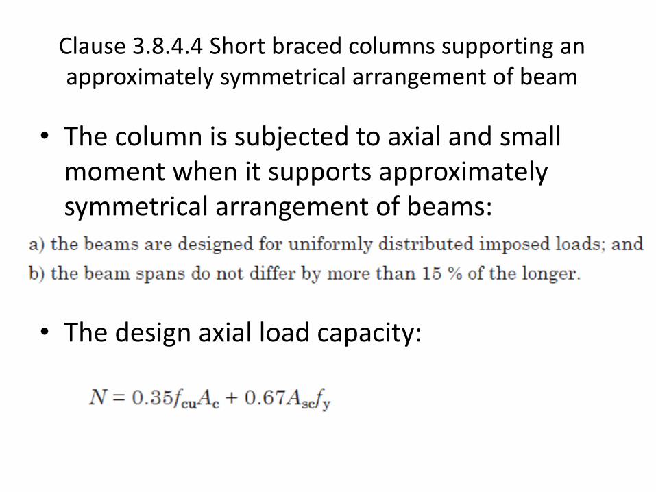
Clause 3.8.4.4 Short braced columns supporting an approximately symmetrical arrangement of beam
• The column is subjected to axial and small moment when it supports approximately symmetrical arrangement of beams:
•
• The design axial load capacity:
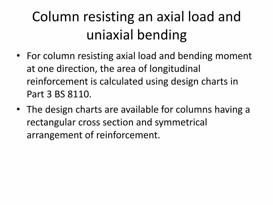
Column resisting an axial load and uniaxial bending
• For column resisting axial load and bending moment at one direction, the area of longitudinal reinforcement is calculated using design charts in Part 3 BS 8110.
• The design charts are available for columns having a rectangular cross section and symmetrical arrangement of reinforcement.
Column resisting an axial load and uniaxial bending
• Design charts are derived based on yield stress of 460 N/mm2 for reinforcement steel. They are applicable for reinforcement with yield stress of 500 N/mm2, but the area of reinforcement obtained will be approximately 10% greater than required.
• Design charts are available for concrete grades – 25, 30, 35, 40, 45 and 50.
• The d/h ratios are in the range of 0.75 to 0.95 in 0.05 increment.
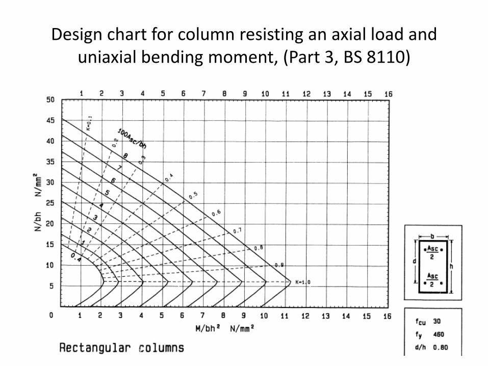
Design chart for column resisting an axial load and uniaxial bending moment, (Part 3, BS 8110)
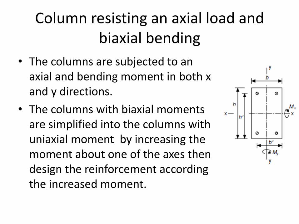
Column resisting an axial load and biaxial bending
• The columns are subjected to an axial and bending moment in both x and y directions.
• The columns with biaxial moments are simplified into the columns with uniaxial moment by increasing the moment about one of the axes then design the reinforcement according the increased moment.
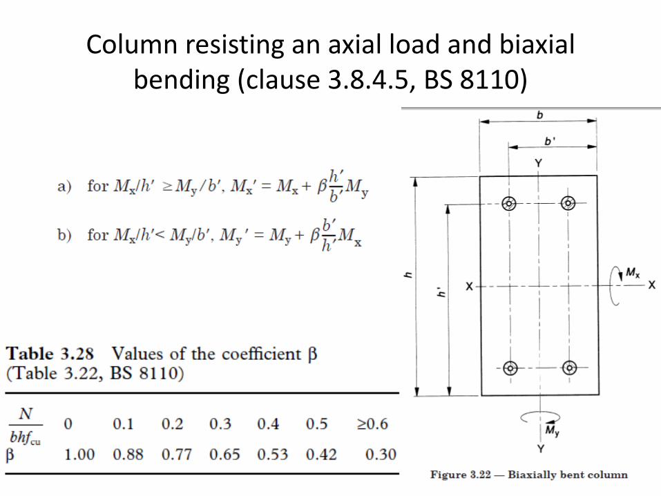
Column resisting an axial load and biaxial bending (clause 3.8.4.5, BS 8110)
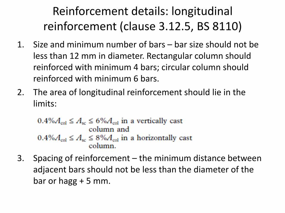
Reinforcement details: longitudinal reinforcement (clause 3.12.5, BS 8110)
1. Size and minimum number of bars – bar size should not be less than 12 mm in diameter. Rectangular column should reinforced with minimum 4 bars; circular column should reinforced with minimum 6 bars.
2. The area of longitudinal reinforcement should lie in the limits:
3. Spacing of reinforcement – the minimum distance between adjacent bars should not be less than the diameter of the bar or hagg + 5 mm.
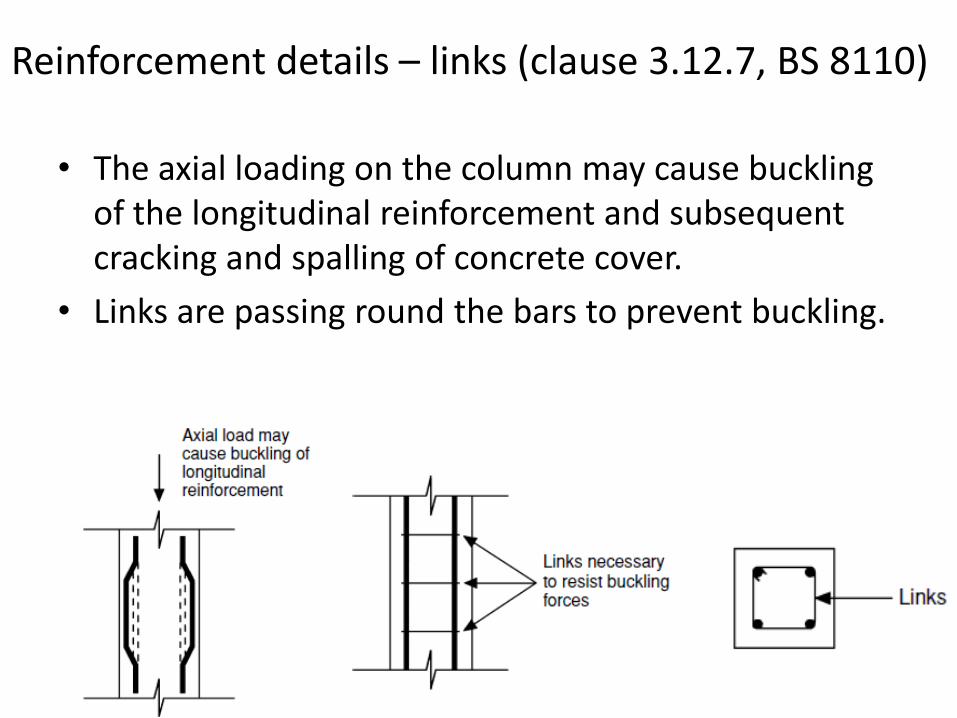
Reinforcement details – links (clause 3.12.7, BS 8110)
• The axial loading on the column may cause buckling of the longitudinal reinforcement and subsequent cracking and spalling of concrete cover.
• Links are passing round the bars to prevent buckling.
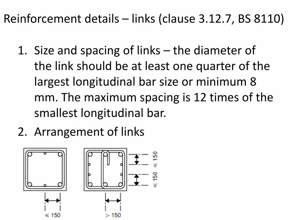
1. Size and spacing of links – the diameter of the link should be at least one quarter of the largest longitudinal bar size or minimum 8 mm. The maximum spacing is 12 times of the smallest longitudinal bar.
2. Arrangement of links
Reinforcement details – links (clause 3.12.7, BS 8110)
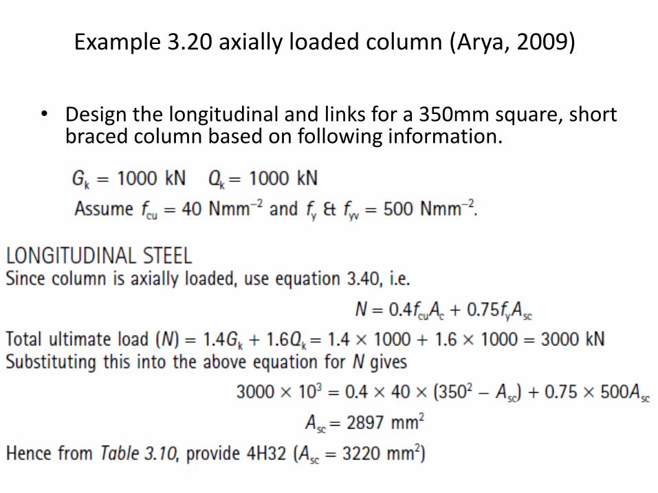
Example 3.20 axially loaded column (Arya, 2009)
• Design the longitudinal and links for a 350mm square, short braced column based on following information.
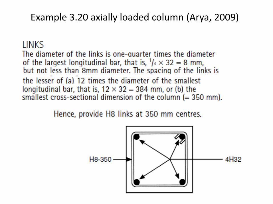
Example 3.20 axially loaded column (Arya, 2009)
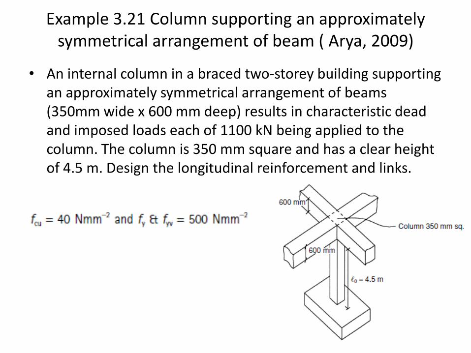
Example 3.21 Column supporting an approximately symmetrical arrangement of beam ( Arya, 2009)
• An internal column in a braced two-storey building supporting an approximately symmetrical arrangement of beams (350mm wide x 600 mm deep) results in characteristic dead and imposed loads each of 1100 kN being applied to the column. The column is 350 mm square and has a clear height of 4.5 m. Design the longitudinal reinforcement and links.
Example 3.21 Column supporting an approximately symmetrical arrangement of beam ( Arya, 2009)
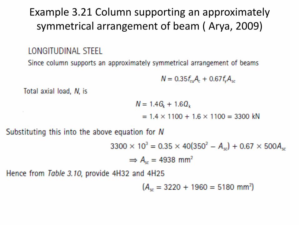
Example 3.21 Column supporting an approximately symmetrical arrangement of beam ( Arya, 2009)
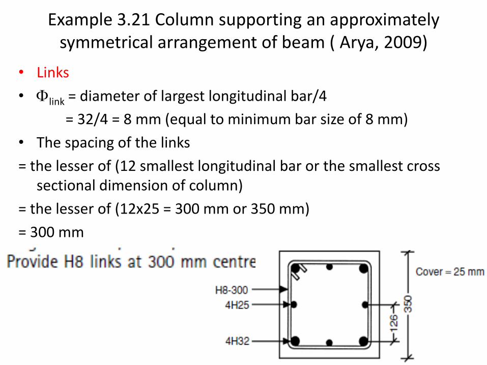
• Links
• Flink = diameter of largest longitudinal bar/4
= 32/4 = 8 mm (equal to minimum bar size of 8 mm)
• The spacing of the links
= the lesser of (12 smallest longitudinal bar or the smallest cross sectional dimension of column)
= the lesser of (12x25 = 300 mm or 350 mm)
= 300 mm
Example 3.21 Column supporting an approximately symmetrical arrangement of beam ( Arya, 2009)
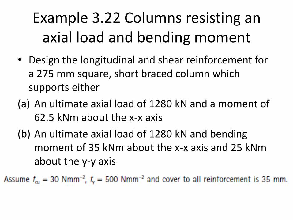
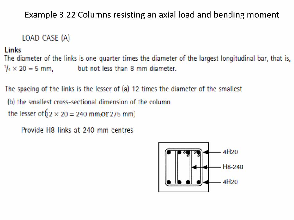
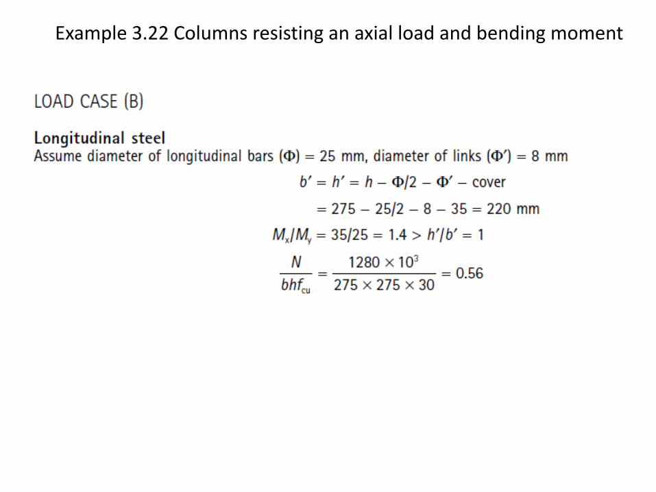
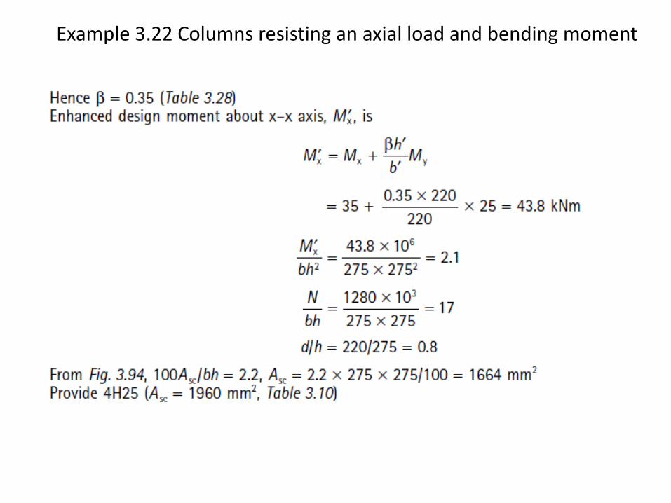
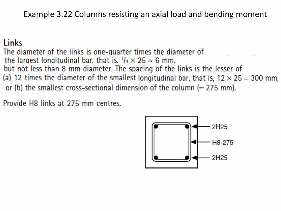
Example 3.22 Columns resisting an axial load and bending moment
• Design the longitudinal and shear reinforcement for a 275 mm square, short braced column which supports either
(a) An ultimate axial load of 1280 kN and a moment of 62.5 kNm about the x-x axis
(b) An ultimate axial load of 1280 kN and bending moment of 35 kNm about the x-x axis and 25 kNm about the y-y axis
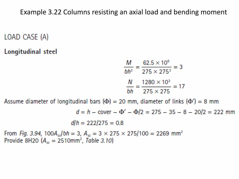
Example 3.22 Columns resisting an axial load and bending moment
Example 3.22 Columns resisting an axial load and bending moment
Example 3.22 Columns resisting an axial load and bending moment
Example 3.22 Columns resisting an axial load and bending moment
Example 3.22 Columns resisting an axial load and bending moment