Embed Size (px)
Citation preview
Relationship-Oriented Architecture: Relationship-Oriented Architecture: A New Paradigm in System A New Paradigm in System
EngineeringEngineering
Tobin Anthony, Ph.D.Tobin Anthony, Ph.D.
Christopher CostelloChristopher Costello
Shawnee Heritage Government SolutionsShawnee Heritage Government Solutions
July 10, 2007July 10, 2007
AgendaAgenda
IntroductionIntroduction The ProblemThe Problem Relationship-Oriented ArchitectureRelationship-Oriented Architecture Example Example Case StudiesCase Studies
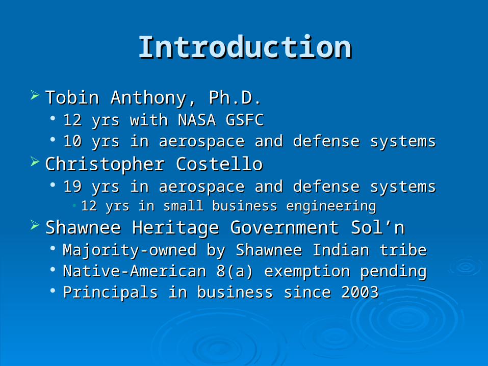
IntroductionIntroduction
Tobin Anthony, Ph.D.Tobin Anthony, Ph.D. 12 yrs with NASA GSFC12 yrs with NASA GSFC 10 yrs in aerospace and defense systems10 yrs in aerospace and defense systems
Christopher CostelloChristopher Costello 19 yrs in aerospace and defense systems19 yrs in aerospace and defense systems
• 12 yrs in small business engineering12 yrs in small business engineering
Shawnee Heritage Government Sol’nShawnee Heritage Government Sol’n Majority-owned by Shawnee Indian tribeMajority-owned by Shawnee Indian tribe Native-American 8(a) exemption pendingNative-American 8(a) exemption pending Principals in business since 2003Principals in business since 2003
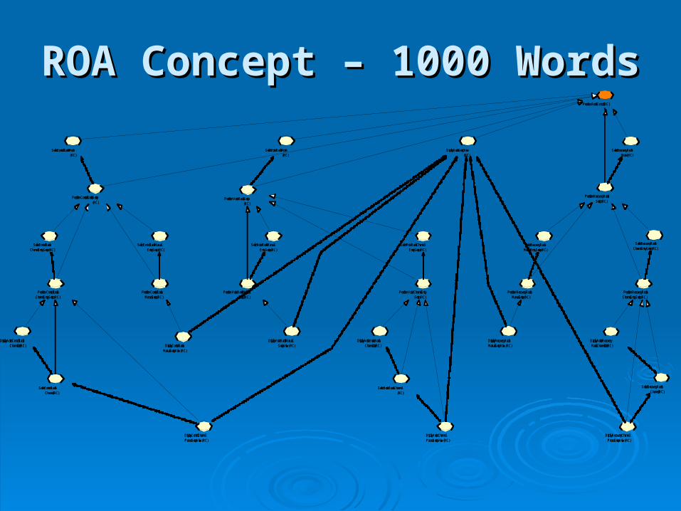
ROA ConceptROA Concept
Simple Is Better Than ComplexSimple Is Better Than Complex A Picture Is Worth 1000 Words A Picture Is Worth 1000 Words
Micromanagement
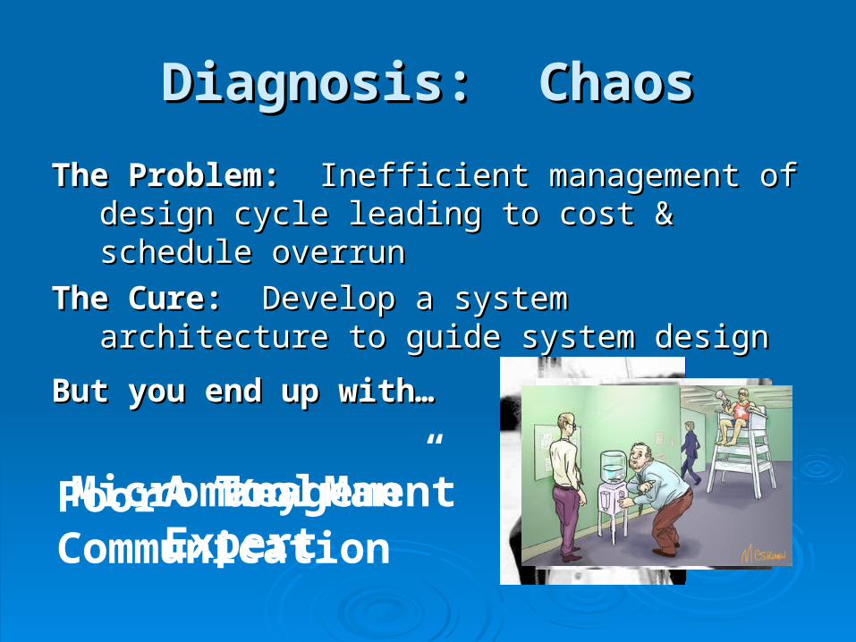
Diagnosis: ChaosDiagnosis: Chaos
The Problem:The Problem: Inefficient management of Inefficient management of design cycle leading to cost & schedule design cycle leading to cost & schedule overrunoverrun
The Cure: The Cure: Develop a system architecture to Develop a system architecture to guide system designguide system design
But you end up with…But you end up with…
A Tool ExpertA “Key Man”Poor Communication
SE 2
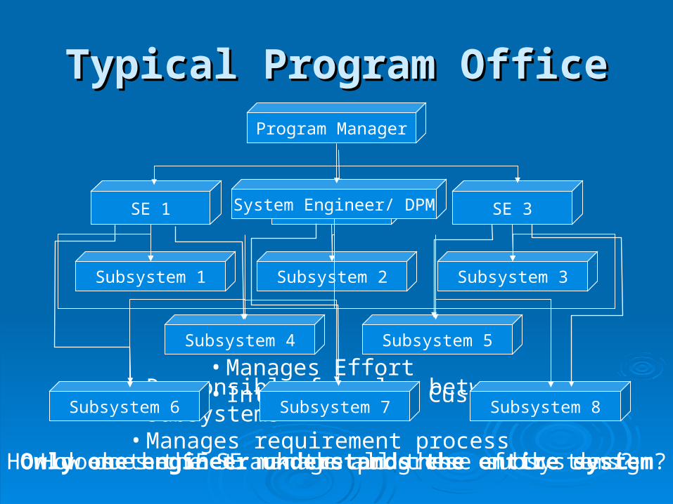
Typical Program OfficeTypical Program OfficeProgram Manager
System Engineer/ DPM
Subsystem 1 Subsystem 2 Subsystem 3
• Manages Effort• Interacts with Customer• Responsible for glue between subsystems
• Manages requirement process
Subsystem 4 Subsystem 5
Subsystem 6 Subsystem 7 Subsystem 8
How does the SE manage all these subsystems?How does the SE track the progress of the design?
SE 1 SE 3
Only one engineer understands the entire system
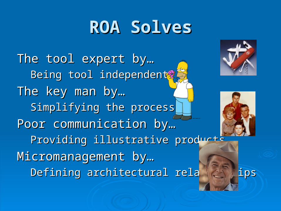
ROA SolvesROA Solves
The tool expert by…The tool expert by…Being tool independentBeing tool independent
The key man by…The key man by…Simplifying the processSimplifying the process
Poor communication by…Poor communication by…Providing illustrative productsProviding illustrative products
Micromanagement by…Micromanagement by…Defining architectural relationshipsDefining architectural relationships
What is ROA?What is ROA?
HistoryHistory Developed by authors for use on UAV ground Developed by authors for use on UAV ground
system programsystem program Honed by years of frustration seeing Honed by years of frustration seeing
programs “winging it” programs “winging it” ConceptConcept
Database, not tool-orientedDatabase, not tool-oriented Simple means of illustrating system by Simple means of illustrating system by
emphasizing relationships between elements emphasizing relationships between elements
ROA Concept - SimplicityROA Concept - Simplicity Rigorous, but not rigor mortisRigorous, but not rigor mortis
Define a core set of system productsDefine a core set of system products• Illustration of the system architectureIllustration of the system architecture
Minimal set to document and communicate the designMinimal set to document and communicate the design Engineer identifies systems elements and defines the Engineer identifies systems elements and defines the
relationship between themrelationship between them Examples of system elements are:Examples of system elements are:
RequirementsRequirements FunctionsFunctions Components (HW or SW)Components (HW or SW) Test proceduresTest procedures Development milestonesDevelopment milestones
Relationships Between Elements Determine How the System Is Used & Built to Meet Requirements
Perform Radio Control (RC)
Select Recovery Radio Mode (RC)
Select Voice Radio Mode (RC)
Perform Recovery Radio Setup (RC)
Perform Voice Radio Setup (RC)
Display Radio Setup View (RC)
Display Voice Radio Manual Setup View (RC)Display Control Radio
Manual Setup View (RC)
Select Control Radio Manual Entry Setup (RC)
Perform Control Radio Manual Setup (RC)
Perform Recovery Radio Manual Setup (RC)
Perform Voice Radio Manual Setup (RC)
Select Recovery Radio Manual Entry Setup (RC)
Select Voice Radio Manual Entry Setup (RC)
Display Recovery Radio Manual Setup View (RC)
Select Recovery Radio Channel Entry Setup (RC)
Perform Recovery Radio Channel Entry Setup (RC)
Display Active Recovery Radio Channel List (RC)
Select Recovery Radio Channel (RC)
Display Recovery Channel Preset Setup View (RC)
Perform Control Radio Channel Entry Setup (RC)
Display Active Control Radio Channel List (RC)
Select Control Radio Channel (RC)
Display Control Channel Preset Setup View (RC)
Display Active Voice Radio Channel List (RC)
Select Voice Radio Channel (RC)
Perform Voice Channel Entry Setup (RC)
Display Voice Channel Preset Setup View (RC)
Select Control Radio Channel Entry Setup (RC)
Select Voice Radio Channel Entry Setup (RC)
Select Control Radio Mode (RC)
Perform Control Radio Setup (RC)
ROA Concept – 1000 WordsROA Concept – 1000 Words
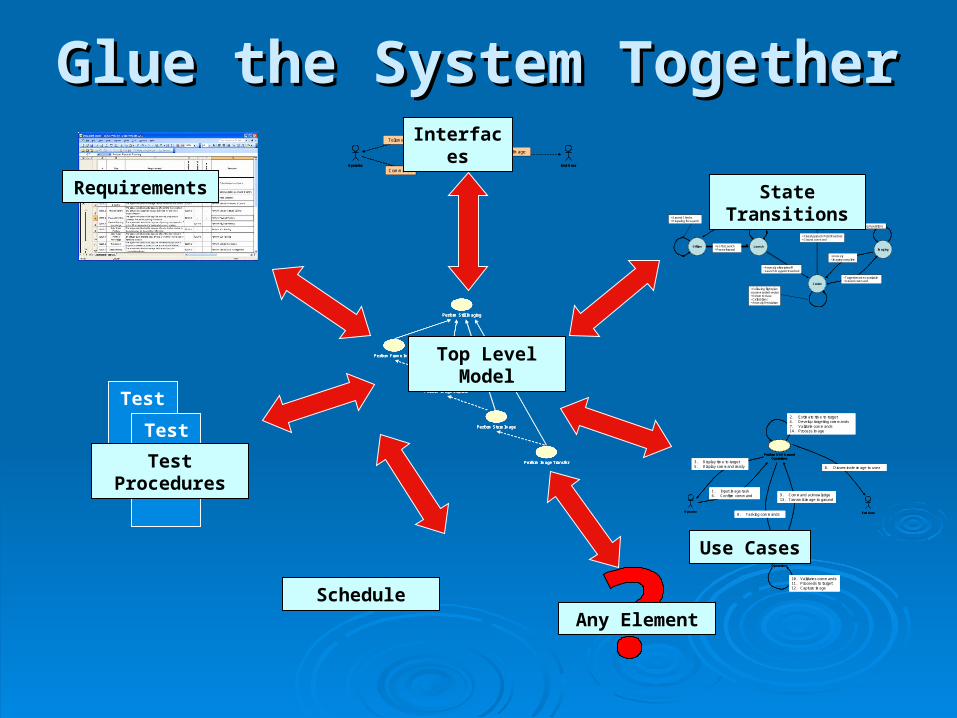
Glue the System TogetherGlue the System Together
Perform Still Imaging
Perform Image Transfer
Perform Store Image
Perform Frame Image
Perform Image Capture
Perform Still ImagingPerform Still Imaging
Perform Image TransferPerform Image Transfer
Perform Store ImagePerform Store Image
Perform Frame ImagePerform Frame Image
Perform Image CapturePerform Image Capture
Top Level Model
Requirements
Perform UAV ImagingOperator End User
Commands
Telemetry
Image
Perform UAV ImagingPerform UAV ImagingOperator Operator End User End User
Commands
Telemetry
Image
Interfaces
Offline Launch
Cruise
Imaging
Landing
• Go for Launch• Power forward
• Anomaly after takeoff• Launch Waypoint Reached
• Target becomes available• Ground command
• Anomaly• Imaging complete
• Final Approach Point Reached• Ground command
• Ground speed = 0
• Gear down• Decent• Brake on Runway
• Imaging Operations
• Following flight plan or commanded vector• Return to Base• Calibrations• Anomaly Resolution
• Ground Checks• Preparing for Launch
State Transitions
Perform Vehicle Operations
Perform UAV Ground Operations
Operator End User
1. Input image task6. Confirm command
2. Estimate time to target4. Develop targeting commands7. Validate commands14. Process image
3. Display time to target5. Display command ready
8. Tasking commands
10. Validates commands11. Proceeds to target12. Capture image
9. Command acknowledge13. Transmit image to ground
8. Disseminate image to user
Perform Vehicle Operations
Perform Vehicle Operations
Perform UAV Ground Operations
Perform UAV Ground Operations
Operator Operator End User End User
1. Input image task6. Confirm command
2. Estimate time to target4. Develop targeting commands7. Validate commands14. Process image
3. Display time to target5. Display command ready
8. Tasking commands
10. Validates commands11. Proceeds to target12. Capture image
9. Command acknowledge13. Transmit image to ground
8. Disseminate image to user
Use Cases
Test
Test
Test Procedures
ScheduleAny Element
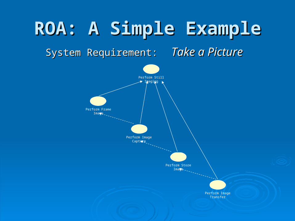
ROA: A Simple ExampleROA: A Simple ExampleSystem Requirement:System Requirement: Take a PictureTake a Picture
Perform Still Imaging
Perform Image Transfer
Perform Store Image
Perform Frame Image
Perform Image Capture
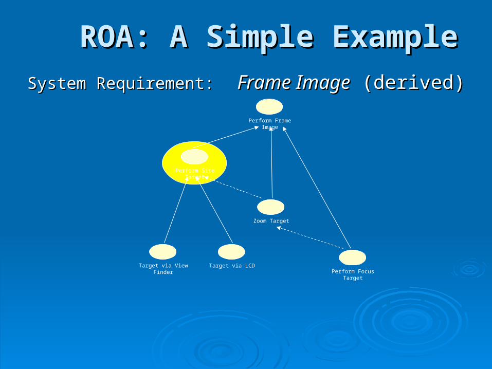
ROA: A Simple ExampleROA: A Simple Example
System Requirement:System Requirement: Frame ImageFrame Image (derived) (derived)
Perform Frame Image
Zoom Target
Perform Site Target
Perform Focus TargetTarget via View Finder Target via LCD
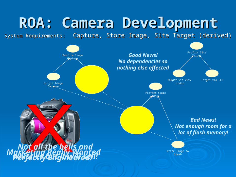
ROA: Camera DevelopmentROA: Camera DevelopmentSystem Requirements:System Requirements: Capture, Store Image, Site Target (derived) Capture, Store Image, Site Target (derived)
Perform Store Image
Perform Image Capture
Single Image Capture Multiple Image Capture
Retrieve Image from Focal Plane
Write Image to Flash
Perform Site Target
Target via View Finder Target via LCD
Perfectly Engineered!Marketing Really Wanted
Good News!No dependencies so nothing else effected
Bad News!Not enough room for a
lot of flash memory!
Not all the bells and whistles but it will sell!
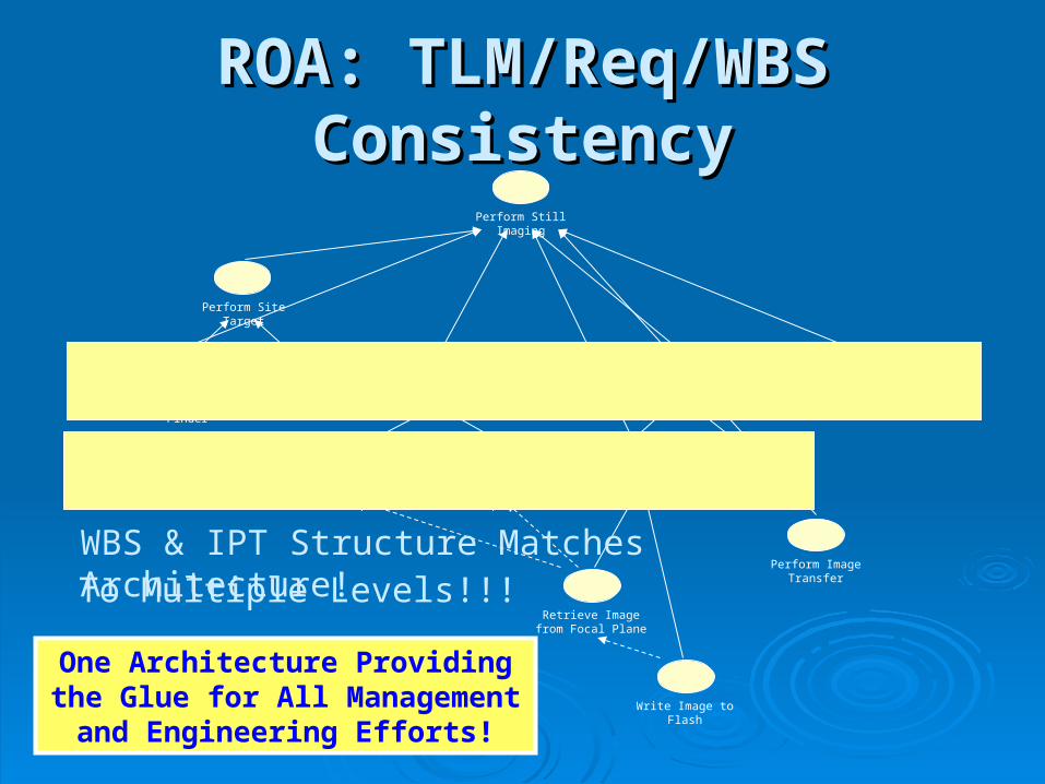
ROA: TLM/Req/WBS ROA: TLM/Req/WBS ConsistencyConsistency
Perform Store Image
Perform Image Capture
Single Image Capture Multiple Image Capture
Retrieve Image from Focal Plane
Write Image to Flash
Perform Site Target
Target via View Finder Target via LCD
Perform Still Imaging
Perform Image TransferWBS & IPT Structure Matches Architecture!To Multiple Levels!!!
One Architecture Providing the Glue for All Management and
Engineering Efforts!
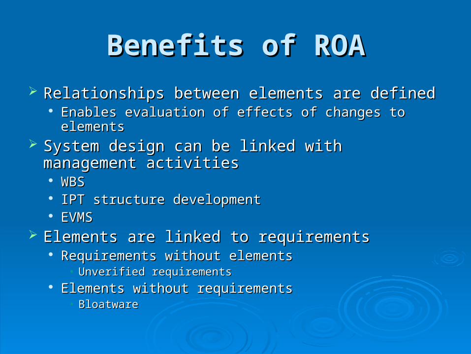
Benefits of ROABenefits of ROA
Relationships between elements are definedRelationships between elements are defined Enables evaluation of effects of changes to elementsEnables evaluation of effects of changes to elements
System design can be linked with management System design can be linked with management activitiesactivities WBSWBS IPT structure developmentIPT structure development EVMSEVMS
Elements are linked to requirementsElements are linked to requirements Requirements without elementsRequirements without elements
• Unverified requirementsUnverified requirements Elements without requirementsElements without requirements
• BloatwareBloatware
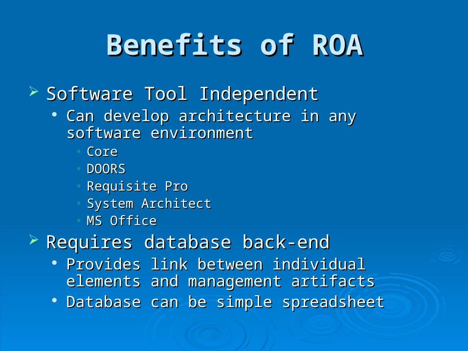
Benefits of ROABenefits of ROA
Software Tool IndependentSoftware Tool Independent Can develop architecture in any software environmentCan develop architecture in any software environment
• CoreCore• DOORSDOORS• Requisite ProRequisite Pro• System ArchitectSystem Architect• MS OfficeMS Office
Requires database back-endRequires database back-end Provides link between individual elements and Provides link between individual elements and
management artifactsmanagement artifacts Database can be simple spreadsheetDatabase can be simple spreadsheet
Case StudiesCase Studies
Bringing UAV Ground System to CDRBringing UAV Ground System to CDR Forensic Analysis of Safehold Mode Forensic Analysis of Safehold Mode
SoftwareSoftware
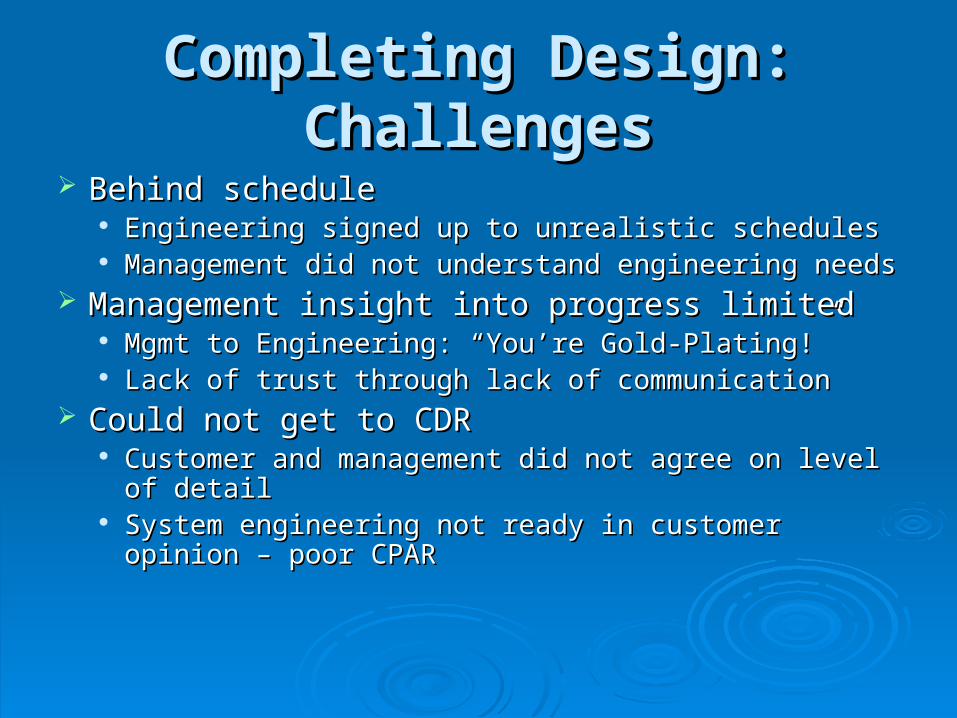
Completing Design: Completing Design: ChallengesChallenges
Behind scheduleBehind schedule Engineering signed up to unrealistic schedulesEngineering signed up to unrealistic schedules Management did not understand engineering needsManagement did not understand engineering needs
Management insight into progress limitedManagement insight into progress limited Mgmt to Engineering: “You’re Gold-Plating!”Mgmt to Engineering: “You’re Gold-Plating!” Lack of trust through lack of communicationLack of trust through lack of communication
Could not get to CDRCould not get to CDR Customer and management did not agree on level of Customer and management did not agree on level of
detaildetail System engineering not ready in customer opinion – System engineering not ready in customer opinion –
poor CPARpoor CPAR
SELECT AIRSPEED
PERFORM VECTOR FLIGHT MODE
PERFORM VEHICLE FLIGHT MODE
PERFORM MISSION PLANFLIGHT MODE
SELECT MISSION PLANFLIGHT MODE
SELECT VECTOR FLIGHT MODE
SELECT ALTITUDE SELECT COURSE SELECT CLIMB RATECOMMANDPLAN AIRSPEED
COMMANDPLAN ALTITUDE
COMMANDPLAN COURSE
COMMANDPLAN CLIMB RATE
COMMANDFLIGHT PARAMETERS
DISPLAY PLAN AIRSPEED
DISPLAY PLANALTITUDE
DISPLAY PLAN COURSE
DISPLAY PLANCLIMB RATE
DISPLAYAIRSPEED
DISPLAYALTITUDE
DISPLAY COURSE
DISPLAYCLIMB RATE
COMMANDFLIGHT MODE
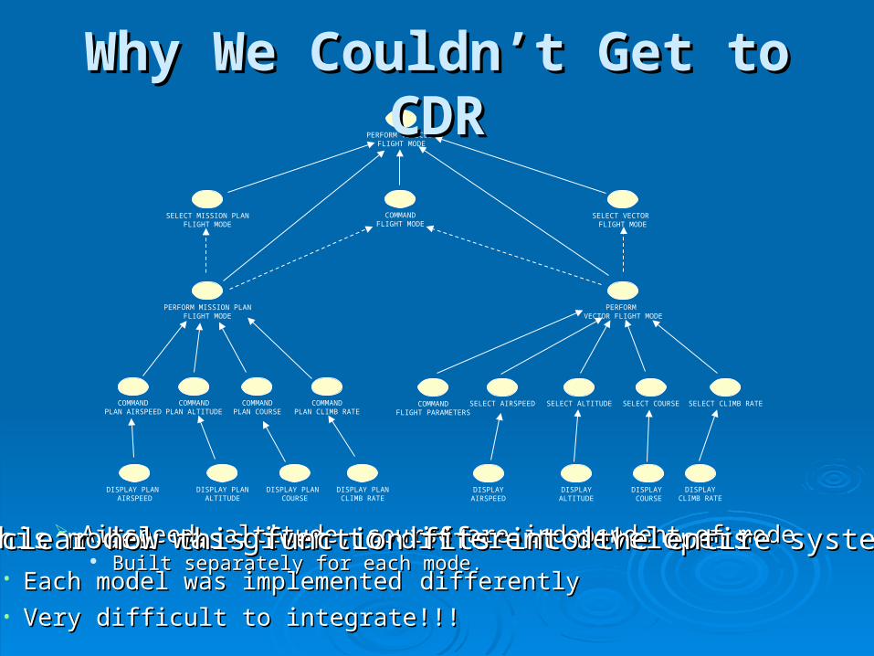
Why We Couldn’t Get to CDRWhy We Couldn’t Get to CDR
Airspeed, altitude, course are independent of modeAirspeed, altitude, course are independent of mode Built separately for each mode.Built separately for each mode.
This model was given to different developersThis model was given to different developers• Each model was implementedEach model was implemented differentlydifferently• Very difficult to integrate!!!Very difficult to integrate!!!
Not clear how this function fits into the entire systemNot clear how this function fits into the entire system
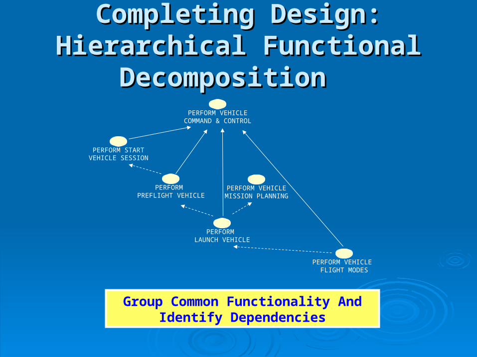
Completing Design: Hierarchical Completing Design: Hierarchical Functional Decomposition Functional Decomposition
PERFORM VEHICLECOMMAND & CONTROL
PERFORM PREFLIGHT VEHICLE
PERFORM LAUNCH VEHICLE
PERFORM VEHICLE FLIGHT MODES
PERFORM STARTVEHICLE SESSION
PERFORM VEHICLEMISSION PLANNING
Group Common Functionality And Identify Dependencies
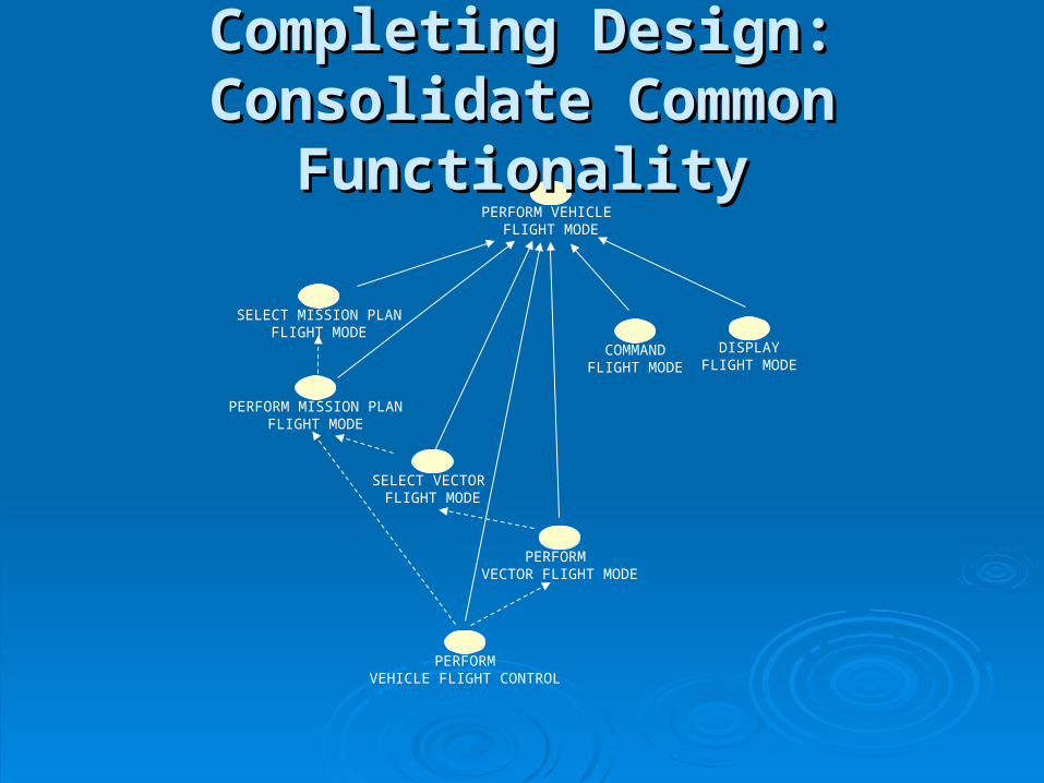
PERFORM VECTOR FLIGHT MODE
PERFORM VEHICLE FLIGHT MODE
PERFORM MISSION PLANFLIGHT MODE
SELECT MISSION PLANFLIGHT MODE
SELECT VECTOR FLIGHT MODE
PERFORMVEHICLE FLIGHT CONTROL
COMMANDFLIGHT MODE
DISPLAYFLIGHT MODE
Completing Design: Consolidate Completing Design: Consolidate Common FunctionalityCommon Functionality
SELECT AIRSPEED
PERFORM VEHICLE FLIGHT CONTROL
SELECT ALTITUDE SELECT COURSE SELECT CLIMB RATE
COMMANDFLIGHT PARAMETERS
DISPLAYFLIGHT PARAMETERS
DISPLAYAIRSPEED
DISPLAYALTITUDE
DISPLAY COURSE
DISPLAYCLIMB RATE
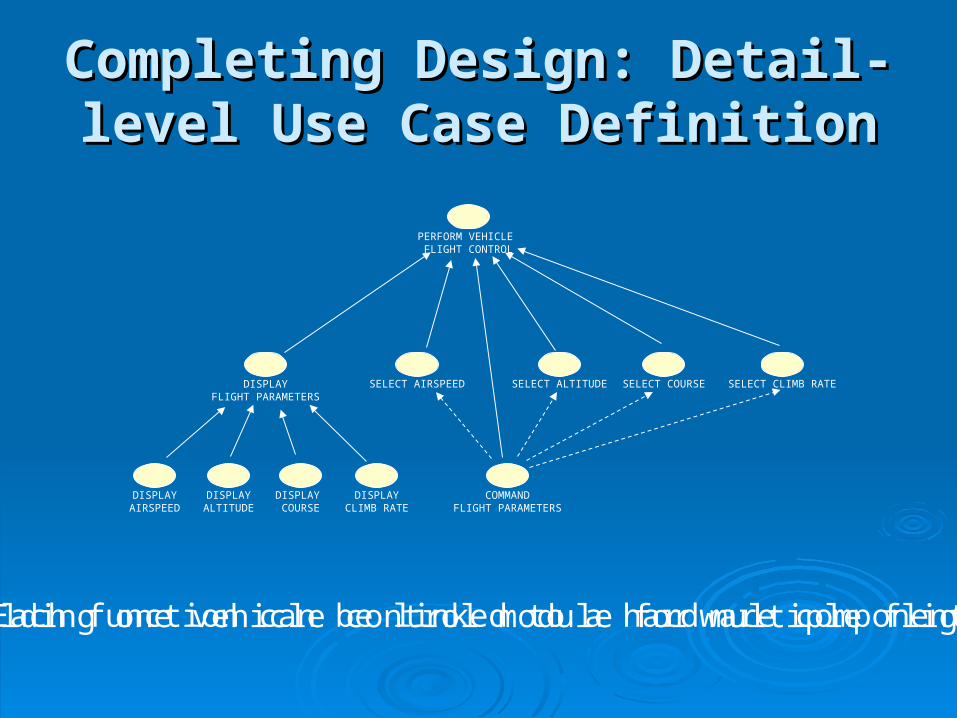
Completing Design: Detail-level Completing Design: Detail-level Use Case DefinitionUse Case Definition
Only building one vehicle control module for multiple flight modesEach function can be linked to a hardware component
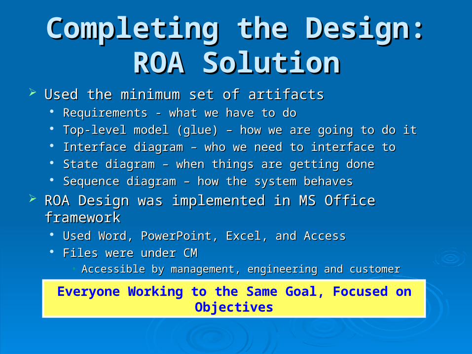
Completing the Design: ROA Completing the Design: ROA SolutionSolution
Used the minimum set of artifactsUsed the minimum set of artifacts Requirements - what we have to doRequirements - what we have to do Top-level model (glue) – how we are going to do itTop-level model (glue) – how we are going to do it Interface diagram – who we need to interface toInterface diagram – who we need to interface to State diagram – when things are getting doneState diagram – when things are getting done Sequence diagram – how the system behavesSequence diagram – how the system behaves
ROA Design was implemented in MS Office frameworkROA Design was implemented in MS Office framework Used Word, PowerPoint, Excel, and AccessUsed Word, PowerPoint, Excel, and Access Files were under CMFiles were under CM
• Accessible by management, engineering and customerAccessible by management, engineering and customer
Everyone Working to the Same Goal, Focused on Objectives
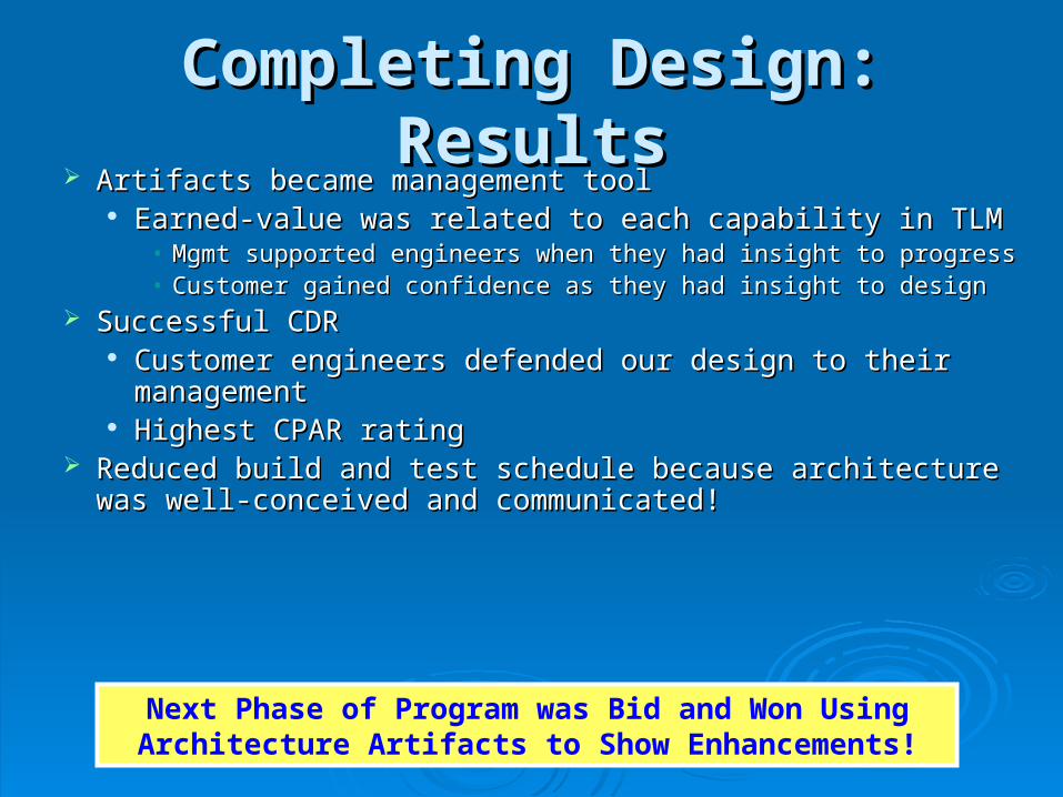
Next Phase of Program was Bid and Won Using Architecture Artifacts to Show Enhancements!
Completing Design: ResultsCompleting Design: Results Artifacts became management toolArtifacts became management tool
Earned-value was related to each capability in TLMEarned-value was related to each capability in TLM• Mgmt supported engineers when they had insight to progressMgmt supported engineers when they had insight to progress• Customer gained confidence as they had insight to designCustomer gained confidence as they had insight to design
Successful CDRSuccessful CDR Customer engineers defended our design to their Customer engineers defended our design to their
managementmanagement Highest CPAR ratingHighest CPAR rating
Reduced build and test schedule because architecture was Reduced build and test schedule because architecture was well-conceived and communicated!well-conceived and communicated!
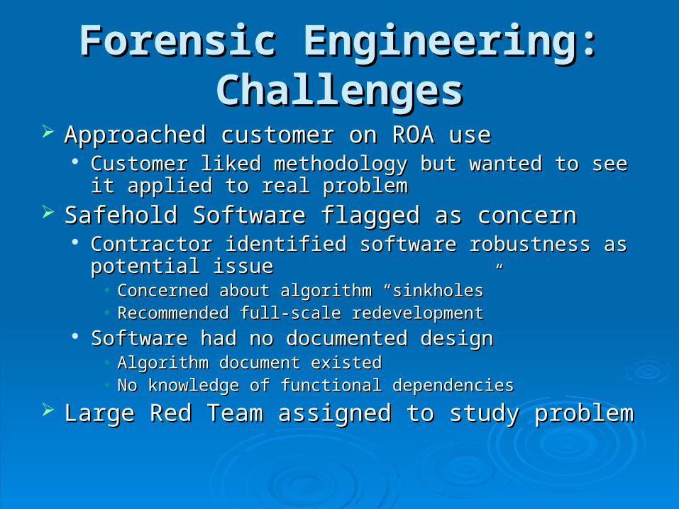
Forensic Engineering: Forensic Engineering: ChallengesChallenges
Approached customer on ROA useApproached customer on ROA use Customer liked methodology but wanted to see it Customer liked methodology but wanted to see it
applied to real problemapplied to real problem Safehold Software flagged as concernSafehold Software flagged as concern
Contractor identified software robustness as potential Contractor identified software robustness as potential issueissue
• Concerned about algorithm “sinkholes”Concerned about algorithm “sinkholes”• Recommended full-scale redevelopmentRecommended full-scale redevelopment
Software had no documented designSoftware had no documented design• Algorithm document existedAlgorithm document existed• No knowledge of functional dependenciesNo knowledge of functional dependencies
Large Red Team assigned to study problemLarge Red Team assigned to study problem
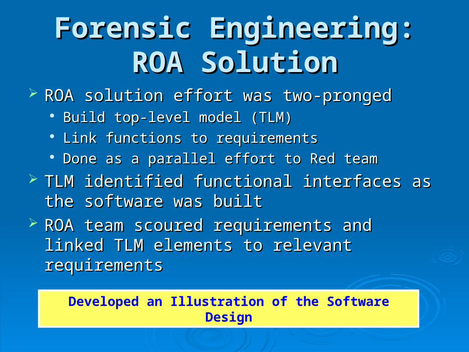
Forensic Engineering: ROA Forensic Engineering: ROA SolutionSolution
ROA solution effort was two-prongedROA solution effort was two-pronged Build top-level model (TLM)Build top-level model (TLM) Link functions to requirementsLink functions to requirements Done as a parallel effort to Red teamDone as a parallel effort to Red team
TLM identified functional interfaces as the TLM identified functional interfaces as the software was builtsoftware was built
ROA team scoured requirements and linked ROA team scoured requirements and linked TLM elements to relevant requirementsTLM elements to relevant requirements
Developed an Illustration of the Software Design
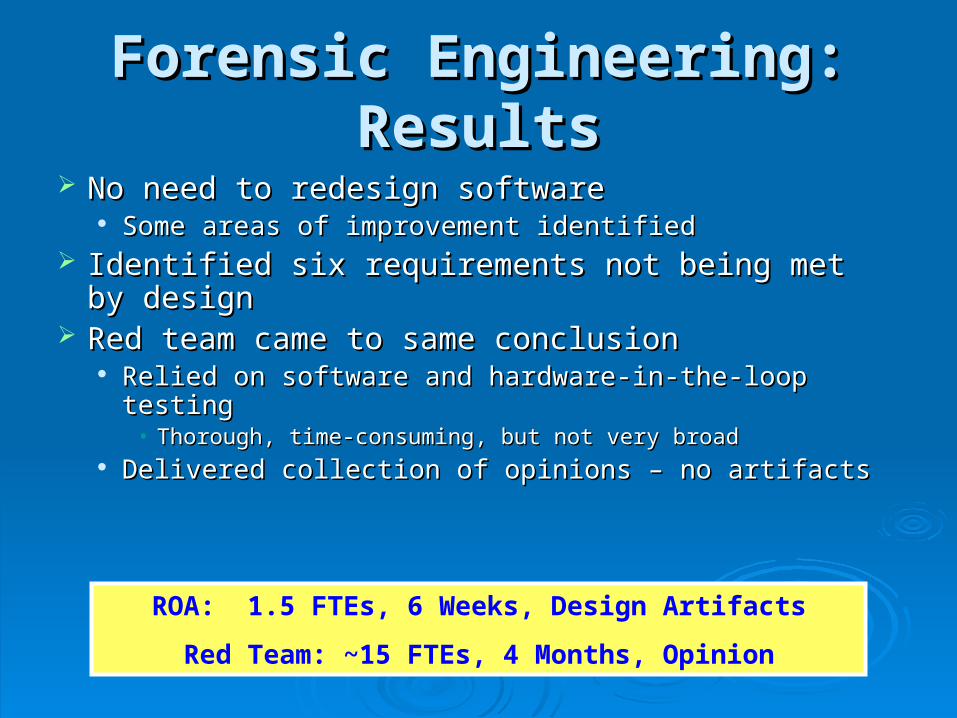
Forensic Engineering: Forensic Engineering: ResultsResults
No need to redesign softwareNo need to redesign software Some areas of improvement identifiedSome areas of improvement identified
Identified six requirements not being met by designIdentified six requirements not being met by design Red team came to same conclusionRed team came to same conclusion
Relied on software and hardware-in-the-loop testingRelied on software and hardware-in-the-loop testing• Thorough, time-consuming, but not very broadThorough, time-consuming, but not very broad
Delivered collection of opinions – no artifactsDelivered collection of opinions – no artifacts
ROA: 1.5 FTEs, 6 Weeks, Design Artifacts
Red Team: ~15 FTEs, 4 Months, Opinion
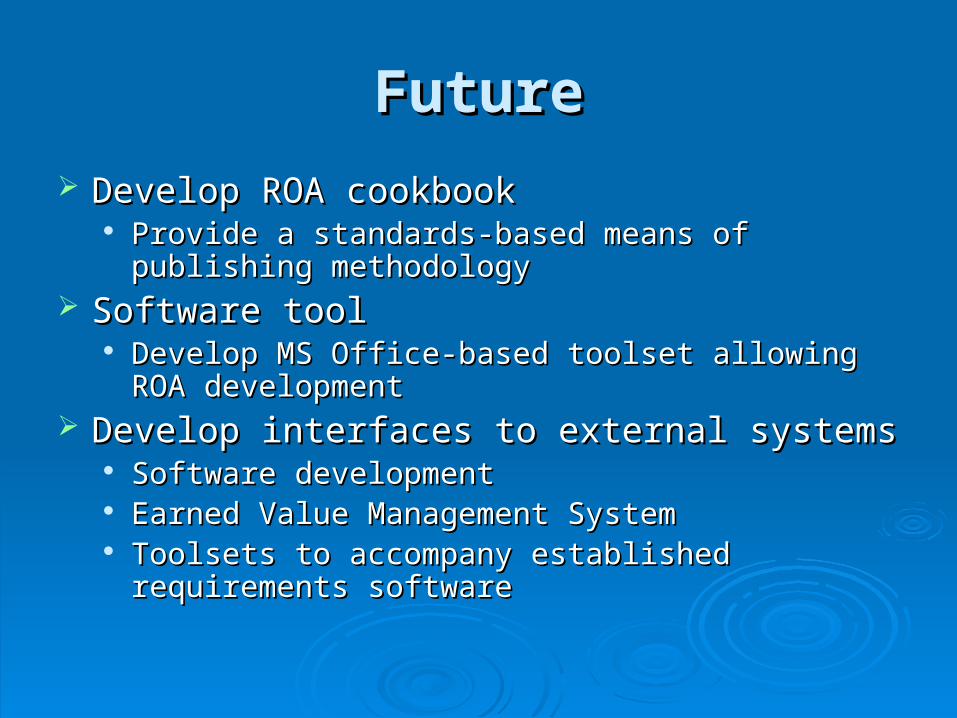
FutureFuture
Develop ROA cookbookDevelop ROA cookbook Provide a standards-based means of publishing Provide a standards-based means of publishing
methodologymethodology Software toolSoftware tool
Develop MS Office-based toolset allowing ROA Develop MS Office-based toolset allowing ROA developmentdevelopment
Develop interfaces to external systemsDevelop interfaces to external systems Software developmentSoftware development Earned Value Management SystemEarned Value Management System Toolsets to accompany established requirements Toolsets to accompany established requirements
softwaresoftware
SummarySummary
ROA enables the system engineer to ROA enables the system engineer to become the system designerbecome the system designer
ROA provides a means of documenting ROA provides a means of documenting system designsystem design
ROA models lead to good implementationROA models lead to good implementation