Embed Size (px)
Citation preview

[ 461 J
RELAXATION METHODS APPLIED TO ENGINEERING PROBLEMS
VIIB. THE ELASTIC STABILITY OF PLANE FRAMEWORKSAND OF FLAT PLATING
By D. G. C hristopherson, L. F ox, J . R. G reen , F. S. Shaw and R. V. Southw ell, F.R.S.
[Received 1 September 1941)
Methods propounded in Part VI of this series, for computing normal modes and the associated frequencies of vibration, are here developed and extended to investigate 6 critical loadings’, and the associated modes of distortion, for plane frameworks and for flat plating in circumstances of ‘neutral elastic stability’. The extension to plane frameworks is straightforward. For flat plating, on the other hand, it is difficult to conjecture even approximately the mode associated with the gravest critical loading, and to meet this difficulty a special technique has been developed. This has proved successful in a case which by orthodox methods seems quite intractable for the reason that the mode is not expressible in terms of known functions.
I ntroduction
3L Problems concerned with elastic stability have not so far received attention in this series, but the outlines of a relaxation treatment have been given elsewhere (Southwell 1940, Chap. xi*). Elastic strain energy, in the nature of the case, is an essentially positive quantity; but another contribution to the potential energy comes from the external forces of a system, and this can have either sign. Consequently the total potential energy measured from any datum configuration can either increase or decrease on account of displacement from that configuration. It will have a stationary value in the datum configuration if this is one of equilibrium; but the stationary value may be a maximum in relation to some particular type of displacement, and in that event we have an example o f ‘elastic instability’.
In most of the cases which are confronted in engineering, the total potential energy as thus measured may be expressed in the form
( 1 )
where 35 j and 35 2, depending respectively on the internal and external forces, are severally homogeneous quadratic functions of the displacements, and where defines the magnitude of the external load system. Both Vi and 352 are then stationary in the datum-configuration, which accordingly is one of equilibrium; but whereas Vi is essentially positive, Pand therefore P. 352 may have either sign, consequently the sign
* Some slight alterations have been made in the amplified account given here.[Issued 14 July 1942—Published 10 October 1945
on May 30, 2018http://rsta.royalsocietypublishing.org/Downloaded from
462 R. V. SOUTHW ELL AND OTHERS ON RELAXATION
of V will depend upon the magnitude and sign of The equilibrium will be stable only if Vis positive for all displacements: it will be neutral or unstable if for any set of displacements P .232, in (1), equals or is greater than Vi, so that V is negative.
In the limiting case of neutral elastic stability, when P has attained a particu lar6 critical' value there is one mode of distortion for which V as given by (1) is zero although Vi and 232 are non-zero. Clearly, when Phas its critical value this mode too is an equilibrium configuration (Southwell 1913, p. 191), consequently V is stationary so that
SV --FV 1--T .FV 2 - - 0 (2)
for all permitted variations of the displacements. We can combine (1) and (2) in the single statement that P as given by
P = %i/®2 (3)
has a value which is stationary in respect of all permitted variations of the displacements. This value is a 6critical value’. For a system characterized by degrees of freedom there are Nsuch values.
2. Now in vibration theory (cfi, for example, Southwell 1940, Chap. vn) the natural frequencies of vibration of a system, i.e. the Eigenwerte of = 27m, can be calculated from the condition that p2as given by
p 2 = 23/2; (4)
has a value which is stationary for all permitted variations of the displacements, 23 and T being essentially positive functions representative of the total potential and kinetic energies. Comparing (3) with (4), we see that when 232 is essentially positive (and this is usually the fact in cases of elastic instability*) the two classes of problem are exactly analogous. Accordingly any method devised for the solution of vibration problems can also be applied to the problems of this paper; and from a practical standpoint the latter are more simple, in that usually only the smallest critical value of is wanted, whereas in vibration problems it is often necessary to determine frequencies higher than the gravest.
In particular, ‘ Rayleigh’s principle ’ is immediately applicable to problems of elastic stability, also the relaxation technique which was based on that principle in Part VI of this series (Pellew & Southwell 1940). For brevity, knowledge of Part VI will be assumed here. Our purpose is to extend the same basic methods to systems of another kind.
3. Two classes of problems will be considered. The first relates to the elastic stability of plane frameworks, consequently is concerned with systems of restricted freedom. The second relates to the elastic stability of flat plating, i.e. of continuous systems.
Timoshenko (1936, §28) has given a number of references to investigations con-
* It is the fact in every problem treated in this paper.
on May 30, 2018http://rsta.royalsocietypublishing.org/Downloaded from

METHODS APPLIED TO ENGINEERING PROBLEMS 463
cerned with the elastic stability of frameworks assumed to buckle in their own planes;* but he exemplifies the problem of transverse buckling (i.e. os the plane of the framework)by one case only—the possible instability of the upper chord of a low-truss bridge (§ 24); and in this, to facilitate the calculations, he replaces the upper chord by a bar with hinged ends which is compressed by forces distributed along its length, and the elastic supports at intermediate (panel) points by an equivalent (continuous) elastic foundation, s Using standard formulae for frameworks (Southwell 1940, Chaps, in and tv), it is now possible to treat frameworks whether plane or three-dimensional,^ and having either pinned or rigid joints, without excessive labour and without simplifying assumptions. Here we consider, very briefly, a simplified example akin to Timoshenko’s but {in one case) involving rigid joints: namely, a 6 W arren’ truss generally representative of a bridge without overhead bracing, but unrepresentative in that (to shorten the computations) all of its members have been assumed to be similar. This will indicate the possibilities of a relaxation treatment.
4. Various examples of elastic instability in flat plating have been discussed by Timoshenko (1936, Chap. vn), mostly on the basis of Rayleigh’s principle (i.e. by energy methods). From a ‘relaxation’ standpoint these problems have novelty in that usually the smallest ‘critical loading’ is associated with a mode which is characterized by nodal lines; consequently it is not easy (as it is, for example, in the strut problem) to make even a fairly close starting assumption in regard to the form of the gravest mode, and difficulty may result from ‘regression’ (cf. Southwell 1940, §252 and footnote). This difficulty is faced in §§ 22-8, where it is surmounted in relation to a case of which the orthodox solution is known: without serious difficulty (though naturally at some cost in labour) the critical thrust is found with an error of only 0 25 %, and still closer results might be expected if the computations were taken further. In §§ 29-32 the methods thus tested are applied to a second example, very much more difficult from an orthodox standpoint. It is, in fact, hard to see how the mode (figure 12) could be represented in terms of known functions: for the relaxation method, on the other hand, this example (though it calls for greater labour) is as straightforward as the first.
In conformity with previous papers of this series, at the outset each example treated is expressed in ‘non-dimensional’ form. The distribution of the loading is specified, and our problem is to compute (approximately) the smallest critical value of a numerical parameter (A) by which the magnitude of the loading is related with the elastic restoring forces.
* All but the simplest of his illustrative frameworks have pinned joints.j This simplified treatment Timoshenko attributes to F. 8. Jasinsky (1902). H. Muller-Breslau and
A. Ostenfeld seem to have dispensed with the assumption of a continuous elastic foundation to replace the concentrated elastic supports.
X Of course, in three-dimensional frameworks all likelihood of instability has usually been eliminated by design ad hoc.
on May 30, 2018http://rsta.royalsocietypublishing.org/Downloaded from

464 R. V. SOUTHW ELL AND OTHERS ON RELAXATION
I . T h e elastic stability of plane frameworks
TO DISTORTION OUT OF THEIR PLANES
Statement of the problem
5. A good deal has been written regarding the tendency of a framework to collapse due to the buckling of one of its members in its own plane (cf. Timoshenko 1936, §28); but the alternative possibility that it may collapse as a whole, , seems to havereceived comparatively little attention. Relaxation methods permit a direct attack on problems of this kind, which we Jhere exemplify by a triangular (Warren) truss of nine bays, built up of members all exactly similar, either 6 pinned ’ or with rigid connexions.
This use of similar members in all parts is not, of course, economical of material; but a truss more representative of practice would present no difference of principle, and would entail a longer discussion. Here we are not concerned with practical aspects, but with the principles of a relaxation treatm ent; so any simplification is legitimate which does not imply restriction, and for a like reason we shall (in assumption) replace the actual stresses of the equilibrium configuration by those resulting from a live load applied (figure 1) to the two middle joints B of the bottom chord. These assumed stresses are recorded in figure 1; they entail
thrusts P, 2P, 3P, 4P in the top-chord members, where P J3 =
Wdenoting the total load on the truss.
Figure 1
(5)
The dead load (being distributed) will entail less widely varying thrust in the top chord; but we shall not be far wide of the mark in assuming that the thrusts are given by (5) by the time that instability supervenes, since the live load will then be predominant if a resonable design factor has been employed. We therefore take the problem to be that of finding, for the load distribution given in figure 1, that value of P for which the elastic equilibrium becomes unstable.
6. Still further to concentrate on essentials, we neglect the slight distortion of the truss (out of its plane) which in practice will result from flexure of the deck system, even when both trusses of the bridge are equally loaded. That is to say, we investigate the elastic
on May 30, 2018http://rsta.royalsocietypublishing.org/Downloaded from

METHODS APPLIED TO ENGINEERING PROBLEMS 465
stability of a side truss on the understanding that the deck system constrains the bottom-chord members to remain in the original vertical plane, and the web members to remain tangential to this plane at their bottom ends, while imposing no constraint on movement of the bottom-chord joints in this plane.
On this understanding, the diagonal members act as cantilevers built in at their lower ends and tending to hold the top-chord members in line. Strictly speaking, their stiffness will depend upon the axial loads which they sustain, and will be greater at the ends .than at the centre of the span. Allowance can be made for this effect (cf., for example, Southwell 1940, §§ 34-9), but here for simplicity it will be neglected.
Similarly, curvature due to flexure of the top chord will affect the distances between the top-chord joints; but these again will be neglected for simplicity, and the approach of two adjacent joints will be taken as dependent solely on their transverse displacements.
7. Consider, for example, the approach of the joints numbered 4 and 5 in figure 1. Considerations of symmetry show that the central joint 5 will remain in the central transverse plane; so, due to transverse displacements and m/5, the member 4-5, retaining its original length L, will be rotated through an angle
and the consequent approach of joint 4 to joint 5 will be given (again, to sufficient approximation) by
Arguing in the same way, we can show that the approach of joint 3 to joint 5 will be given by
We can now deduce the effects of transverse deflexions upon the potential energy of the external loads. They will be accompanied by displacements occurring freely in the plane of the truss, such that the top-chord compressions remain sensibly invariant; and if (as assumed in § 5) these compressions have the values P, 2 P , 3 P ,4P , then the
The expression for 33 2
(to sufficient approximation), (i)
(ii)
(iii)and so on.
Figure 2. (All sloping members treated as clamped at their lower ends.)
on May 30, 2018http://rsta.royalsocietypublishing.org/Downloaded from

466 R. V. SOUTHW ELL AND OTHERS ON RELAXATION
effects of the primary stresses recorded in figure 1 may be represented by external forces of magnitude P ,ac ting as indicated in figure 2. These forces will do work in acting through th e 6 approaches' 8# 83, etc., so reducing the potential energy of the external forces: for example, the force which acts at joint 3 will do work of amount
I PF - ^ = 2 l {{wa- ws)2+ {w$ - w*)2},by (iii), (iv)
and the other forces may be treated similarly. There are (figure 2) eight of these external forces P, acting at the joints 1, 2, 3, 4, 6, 7, 8, 9: allowing for all, we have in the notation of (1), § 1, from (iv) and other equations of similar type,
- P<$ 2 = \ 1 [ K — ^ 2)2+ 2 ( w2- w3)2+ 3 (w3 - w4)2+ 4 (w4 w5)2+ 4 (u>5 - w6)2+ 3 ( — wj)2 + — 2 -f ( — 2] . (6)
The expression for 5B1(I) Pin-jointed top chord
8. A very simple illustration of §§ 1-2 is provided by that case of our problem in which the top-chord members are ‘pinned’ both to one another and to the supporting web members. In it resistance to transverse displacement of a top-chord joint comes from the web members alone, and it has (on the simplifying assumption of § 6) the same value for every joint.We may say that a transverse deflexion wis resisted by a transverse force kw;and then the increase of strain energy which results from displacements wl3 ..., is given by
FVi — \k{w \-f M>|+...
A
Figure 3
(7)
9. Means for evaluating kis provided by the standard formulae of ‘ grid frameworks ’ (Southwell 1940, Chap. in), viz.
For the fixed end:B _lF — ppF Cl2 — 2
~ L :Cm2 — 2
~ L :
~ ~ a B _ _ C + 2 B ,-pzp— zpF— 6 £2 M) qzF— zqF — 6 /, qpp —pqF --— lm j(8)
For the end which is moved:
- 1 2 BL3
PZM — ZPmBI 2
— Cl2+ 4tBm2PPm ~ ,
_ Cm2 + 4P/2 QQm jr 5
QzM = zqM= 6 -p /, qpM — pqM — ^(9)
on May 30, 2018http://rsta.royalsocietypublishing.org/Downloaded from

METHODS APPLIED TO ENGINEERING PROBLEMS 467
C and B denote respectively the torsional and the relevant flexural rigidity of a component member (here assumed to have uniform cross-section). I and m are direction cosines of the line drawn from the moved end to the fixed end
The joint A ,in figure 3, undergoes displacements p, q which (on our present assumption that the top-chord members are attached to by 6 pinned ’ joints) must entail a force Z and moments Land M on the ‘constraints’, given by
Z = —kw, L — = 0 . (10)
Hence, according to the formulae (8) and (9), we have
■kw Z = — 2 4 ^ L6 2 61 1 3L2 P + 0,
L
0 = M = 0 + 0 - 2
and from these equations we deduce that
C
(SC+4:B\(— T T +
and
0, ^3 + Lp—
B_U 1 + C/12BJ
B
( 11)
= 6^3, nearly, when is small.
(2) Truss having rigid joints in top chord
10. When all of the joints are rigid, formulation of Vi is somewhat more difficult, but can still be effected with the use of (8) and (9), § 9. Using these to find the effects upon the ‘ forces on constraints’ of rotations p2,q2 and displacements of the joint 2in figure 1, we have
Due to unit displacement w2:Zi -- 12Æ/Z,3, Z2 = -48B /Z 3, Z3 = 12
L\ = 0, L2 = — 6 J3B/L2, o'
4
Ml = — QB/L2,
otation p2:
M2 = 0, M3 = GB/L2,
Z\ — 0, Z2 = —QjSB/L2, Z3 = 0,
•4II4
L2 =-(5C + 12B )/2Z , z 3 = c m
M = 0, 11 a> o'IIas
V ol. 239. A 57
on May 30, 2018http://rsta.royalsocietypublishing.org/Downloaded from

468 R. V. SOUTHW ELL AND OTHERS ON RELAXATION
Due to unit rotation *
Zi = 6Z/Z2, Z2 — o, Z3 = — 6Z/Z2,
Jh< 1 o Z2 — o, II
M = - 2 Z/Z, M2 = -(3C + 20Z )/2Z , Af3 = -2 Z /Z .
Joints 1 and 9 call for special treatment. We have
Due to unit displacement wx:
Z x —— 36Z/Z3,
L x
Mx = 6 Z/Z2,
Due to unit displacementpx:
Z x = — 6
L x == —3(C+4J5)/2L,
M = o,
Due to unit displacement :
Z x = 6Z/Z2,
L x — 0,
Mx = —3(C4-4Z)/2Z,
Joint (9) may be treated similarly.
Z2 = 12 Z/Z3,
^2 = 0,M2 = 6Z/Z2,
Z 2 — 0,
l 2 = c m
M2 — 0,
Z2 = - 6 Z / Z 2,
L 2 — 0,
M2 = -2 B /L .
11. Using these results, since all Z’s and As’s must vanish as in (10) when account is taken of the top-chord members as well as of the web members, we can formulate nine equations starting with
/ 3 C\ C 16*/3 wl Jr \^ - \--- j^L p l — -gLp2 = 0,
6N/3M>2 + |6 + --g jz /> 2—-g Z ^ + ^ g ) = 0,
........ , etc.,
( 12)
and nine equations starting with
wi ( l ~^47?) = O)
^ i — u)3—^L(ql -{-q3)— 3 ' 4Z Lq2
, etc.
0,(13)
on May 30, 2018http://rsta.royalsocietypublishing.org/Downloaded from

METHODS APPLIED TO ENGINEERING PROBLEMS 469
We can solve these to obtain expressions for every and in terms of the and then,using the material of § 10 again, we can formulate expressions in w2, ..., for the forces opposed to transverse displacement, i.e. for ..., Hence 931 canbe calculated for the truss with rigid joints.
Consequences of symmetry
12. Whether the joints be pinned or free, the symmetry of the truss and of the load system permits us to separate the modes of distortion into two classes, the first symmetrical and the second 6 skew-symmetrical ’ with respect to the central point 5. In the first class
W\ ~ w9’~ ^8, WZ ~ — Wg, 'j
Pi ~ p9> Pi ~ Pe’5s! "b 9 = (72~f~78 ~ = ^4"b 6
and in the second class
(14 A)
w1 + w9 — w2 + Wq = = = w5 ----- 0,
Pl+p9p2 + p8 = P$ + Pl = = 0,-r
*7l ” 0.9) 7 2~ 8> 3 == 3 4 = ^6'
It will be convenient to make the separation into classes at this stage.
(14B)
Solution for the truss with pinned joints in top chord
13. Thus the expression (6), which gives $ 2 in relation to a truss of which the top- chord members are pinned, reduces to
p- P . $ 2 = -£ [ (Wi - w2)2 + 20 2 - W3)2 + 3 (w3- w4)2 + 4 - 2] (6A)
in relation to modes of the first class, for which (14 A) are satisfied. In relation to the second class, for which (14B) are satisfied, it reduces to
„ PP. ~ ^ [(^1 m>2)2 + 2(m/2— w3f — 2 + 4 ^ j . (6B)
Similarly, the expression (7) for reduces to
Vi = P [2 {w\ + w| + zy§ + w\) + w§] (7A)
in relation to the first class, and to
Vi = k{w\ -\-w\-\-wl (7B)
in relation to the second, kbeing given in both instances by (11) of § 9.57-2
on May 30, 2018http://rsta.royalsocietypublishing.org/Downloaded from

470 R. V. SOUTHW ELL AND OTHERS ON RELAXATION
14. Substituting in (1) of § 1, we can deduce for any assumed mode (by Rayleigh’s principle) an estimate of the critical value of From (2), replacing by(dSBJdWf., d%2/dwk) xw k, and giving kthe values 1, 2, etc. in turn, we can deduceequations which define the modes of distortion.
For symmetrical modes of distortion the critical thrust P is given by
= ( P/kL)[2(ro,-to2)2+4(ro2- to 3)2 + 6(to3- to 4)2+8(to4- to 5)2], (ISA)
and w l3 ..., w5 are related by the equations*
2wl ----- {P/kL) x (2wl - 2 w 2), ----- x (14w4- 6 m;3- 8 h;5),'
2w2 ----- {PjkL) x (6w2 — 2wl — 4:W3),w5 ---- (P/kL) x —8
2w3 — (P/kL) x (10w3 — 4tw2—6w4),(16A)
For antisymmetrical modes of distortion the critical thrust is given by
wj + wl + wj + wl---- (P/kL) [(ivl - w 2)2-\-2(w2- w 3)2 + 3(w3 — w4)2 + 4:wl], (15B)
and wXi ..., w4 are related by
wi — (R/^L) x (wl — w2),w3 — (P/kL) x 3i04),lI f 16B)
W2 ----- (P/kL) x (Zw2- w l - 2 w 3),w4 ---- X (7w4-3wz). J V
From a practical standpoint (cf. § 2) interest centres, for either class, in the lowest admissible value of P/kL and the mode with which it is associated. Which of the two ‘ lowest values ’ of P/kL, as thus defined, will be the lower can hardly be predicted, but when found it will be the quantity which is required.
Results for the truss with pinned joints in top chord
15. Tables 1 and 2 record results obtained by D. G. G. and L. F. for the pin-jointed truss, viz. solutions of (16A) and (16B). The modes numbered (1), (4) and (6) were obtained both by orthodox and by ‘relaxation’ methods. All can be easily verified.
Figures 4 and 5 exhibit these modes of distortion. They are striking, in that the mode associated with the smallest critical thrust has the most numerous inflexions. According to (11) the parameter
P __P L 2 I[a 3 \kL 6 B /V 1+C/12BJ' (17)
Pand Ware related by (5), § 5.
* Numerical multipliers have been left uncancelled, to illustrate the reciprocal relations between coefficients.
on May 30, 2018http://rsta.royalsocietypublishing.org/Downloaded from

METHODS APPLIED TO ENGINEERING PROBLEMS 471
T able 1. Symmetrical modes of to p-boom distortionmode
num ber P/kL wx — w2 — IV Q w3 = w1 w4 = iv6 Mz(1) 0-073004 1 -12-698 67-436 -187-07 262-66(2) 0-15193 1 - 5-5821 9-4968 - 1-2864 - 7-2570(3) 0-3458! 1 - 1-8918 — 0-60235 0-83797 1-3124,(4) 1-2068 1 0-1714 -03139 - 0-5507 - 0-6142(5) oo 1 1 1 1 1
T able 2. Skew-symmetrical modes of to p-boom distortion (iy5 = 0)mode
num ber P/kL vox = — = - tog w3= —w7 w4 = — w6(6) 0-10644 1 -8395 26-343 -32-996(7) 0-22043 1 -3-5366 2-2172 2-7002(8) 0-57280 1 -0-7468 -09677 - 0-5525(9) 3-1007 1 0-6774g 0-4069g 0-18289
o
Figure 4. Symmetrical modes (pinned joints in top chord).
Mode No. 1. P/kL = 0-0130 Mode No. 4. P M ---1-2068Mode No. 2. P M --0-1519 Mode No. 5. ooMode No. 3. P M ---0-3458
on May 30, 2018http://rsta.royalsocietypublishing.org/Downloaded from

472 R. V. SOUTHW ELL AND OTHERS ON RELAXATION
Figure 5. Anti-symmetrical modes (pinned joints in top chord).
Mode No. 6. P/kL =0-1064 Mode No. 8. P/AT = 0-5728 Mode No. 7. P/AT = 0-2204 Mode No. 9. P/AT = 3-1007
Solution for the truss with rigid joints in top chord
16. The formulation of 931 for this case was left unfinished in § 11. In symbols the expressions resulting from (12) and (13) are lengthy, and it will be better to give its numerical value, at this stage, to the ratio C/B. This value of course depends upon the cross-sectional shape of the component members. For circular cross-sections (whether solid or hollow)
B/C — E l J si J — 1 + tr — 1-3 approximately, for steel. (18)
We have given this value to P/C* in the work which follows.
17. The symmetrical and the anti-symmetrical modes can again be separated. For the first (in which (14 A) are satisfied) equations (12) become
= —7-154j&1Z,+0-7692j&2Z,,
6V3ty2 = -7-923/>2T + 0-7692(/>1+/>3) L,
673 m/3 = -7 -923A$Z + 0-7692(A> + p4) L,I (12A)6 73 w4= - 7-923/>4T + 0-7692(/>3+/>5) Z,
673 w5 = —7-923/>5T + 0-7692 x2p4L,
on May 30, 2018http://rsta.royalsocietypublishing.org/Downloaded from

METHODS APPLIED TO ENGINEERING PROBLEMS 473
and equations (13) become7T54gr1Z,+ 2q2L = 6(wl — w2),'
% 3 + ? l ) + n *1 5 4
2(q2 + q4) + l l ‘l54: £3 L = ~6(to2 —to4),
2<?3Z + 11T54 = 6(to3 —to5)./From (12 A) we deduce that
- p xL = 1 *46813 wx + 0-14390 w2 + 0-0141 lw 3 + 0-00140 to4 + 0-00014
—p2L--- 0-14390 toi + 1-33837 to2 + 0-13120to3 + 0-01298to4 + 0-00126to5,
—pzL = 0-01411 tox + 0-13120 to2+ 1-33725 to3 + 0-13232 to4 + 0-01285 to5, >
—p4L--- 0-00140 to! + 0-01298 to2 + 0-13232 to3+ 1-34996 to4 + 0-13106 to5,
—p5L = 0-00028 to! + 0-00252 to2 + 0-02569 to3 + 0-26212 to4+ 1-33711 to5,
(ISA)
(19A)
and from (13 A) thatqxL = 0-72050 wl - 0-85416 to2 + 0-15861 to3 - 0-03040 to4 + 0-00545 to5,'
q2L = 0-42277 toi + 0-05533to2 —0-56735 to3 + 0-10874 to4 —0-01949 to5,
qzL = — 0-07829 to: + 0-54559 to2 + 0-00550 to3 - 0-57604 to4- 0-10324 to5, >
q4L -- 0-01404 tox-0-09783 to2 + 0-53694 to3 + 0-10329 to4- 0-55644 to5,
q5L — 0. ;
(20A)
T able 3. Symmetrical modes of top-boom distortionmode
number PL2/B W l — w2 = w8 W% — Wj w4 = w6(!) 3-173 1 -1-8489 -11-0740 -3-9646 32-1543(2) 4-602 1 -7-6373 -14-1414 15-6751 10-2733(3 ) 7-666 1 3-6422 - 1-4569 -1-9479 -2-4743(4) 13-178 1 -0-0466 - 0-2906 -0-4347 -0-4656(5 ) co 1 1 1 1 1
Consequently we have, using the material of § 10 again, and writing (for example) — dSBJdw! for Z xas explained in § 11,
dw\ ~ dtog ~~ &[5m;i ~ 2to2+ J S p lL — (^1 + 2)
/991 f)91 (\RJw2 = lh»i = 1 5 [ - 2wl + 8to2 - 2to3 + JSp 2{q^-qx)
= ItoJ = 1A [-2 to 2 + 8to3-2 to 4 + N/3^3Z - (q4- q 2) L], >
^ ^ ~ 2^ 3 + 8^ 4 - 2to5+ V3/>4 L - ( r5 - L],
= - j j ( - 4:W4 + 8w5-{-j3p5L + 2q4L)
(2!)
on May 30, 2018http://rsta.royalsocietypublishing.org/Downloaded from
474 R. V. SOUTHW ELL AND OTHERS ON RELAXATION
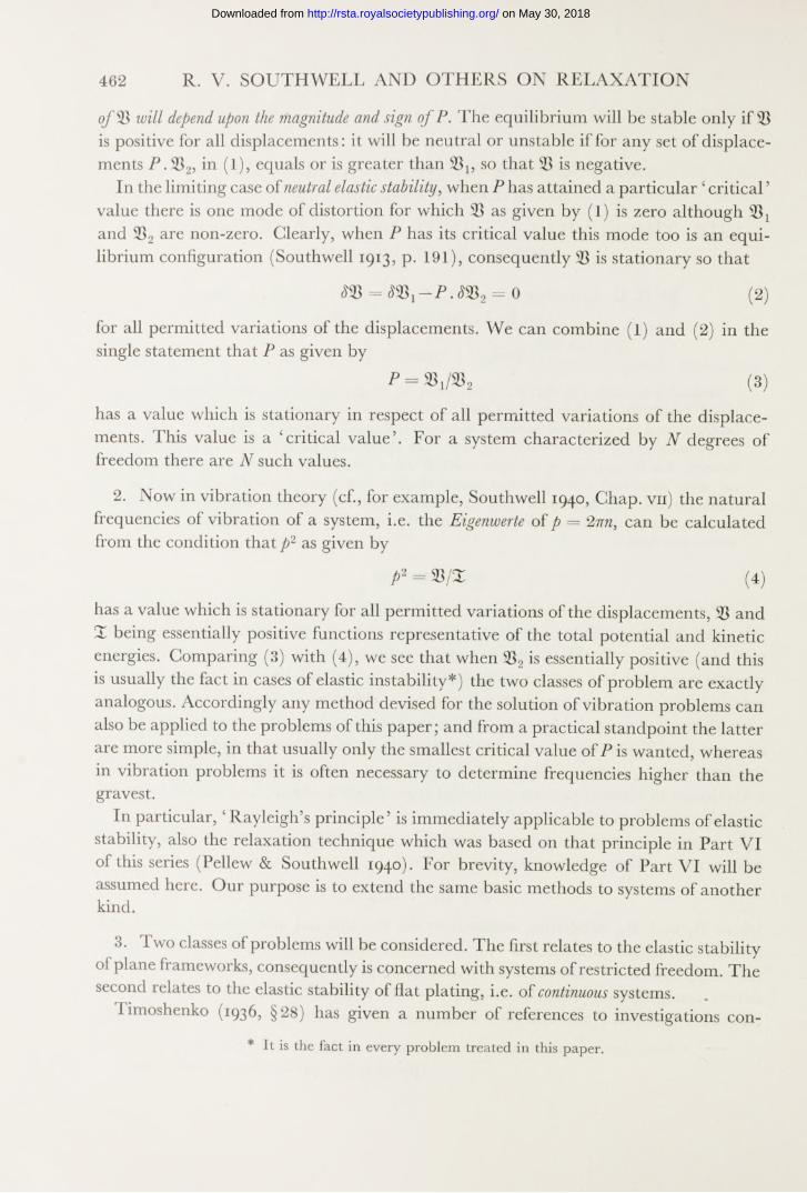
Hence we deduce the expression
V, W , .dwl
ffl{ ]9dWgJ ’ by a known property of quadratic forms,
1 7?= - [27-7662M/f + 51-3870.M/1 + 54-9556 + 61-0304
+ 27-4272 «>§ - 34-8100 10 j w2 + 9-2232 -1-9372 m/4
+ 0-3308 49-7788 w2w3+12-5536 w2rt,4- 2-3996 w2w5
- 53-3692 m/3w4 +12-3528 w3w5- 50-9688 w4w5\,
pt L- 2-626 ps L= -41
» -1-045 frL - 06J9 fyL
”3794 ftL ~ 5-546 f t l
*/5l4$ -4 455
//
//
//
\ \\
1 X\\
r V ____
pL- -0-193 ftL* 11-717 p,L» If 692 pL - -!J- 463
V __________\\\
p L - -1-969 p L - -4-799pf L‘ 1-746 p,L- -3847----- 7*" ' 7s I 7#*- .w
k \ X
-J-457 frL* - 0-725 CfrL”
--------- ^
//
/
-0-037 faLm0 444 p4L*0-686 pyL0547 (fri* 0-097 fyL* 0 077 fyL
I \ _ /
- 0743 «0
_____________^
pL • p,L • p,L - p4L - -1-628f L " f t 1 - 1*!- * fcL- m O
Figure 6. Symmetrical modes (rigid joints in top chord).Mode No. 1. PL2 jB = 3-113Mode No. 4. 13-178Mode No. 2. PL2\B =4-602 Mode No. 5. ooMode No. 3. PL2jB = 7-666
(22 A)
on May 30, 2018http://rsta.royalsocietypublishing.org/Downloaded from

METHODS APPLIED TO ENGINEERING PROBLEMS 475
from which, and from V? as given in (6 A) of § 13, an operations table can be deduced in the usual way.* Then the critical loadings and associated modes can be determined by the standard methods of Part VI (Pellew & Southwell 1940; cf. also Southwell 1940, Chaps, vii and vm), with results which are recorded in table 3 and exhibited in figure 6.
18. For antisymmetrical modes (in which the relations (14B) are satisfied) equations (12) become
6s/3w l = ~ f7-154tp1L + 0-7692p2L,
6 J 3w2H - 7 9 2 3 p2L + 0-7692 L,
Qj3 w3 = - 7-923A jZ, + 0-7692 (p2+ p 4) L,
6^/3 w4 = - 7-923 p4L+ 0-7692/?3L ,
(12B)
and equations (13) becomefl-154tqlL + 2q2L —
% 1 + t i + 11-154 ^ = 6(tt-i-wz),
2 (<?2 + <74) +11*154 q$L w4),
2(23 + 25) + 11-154 24- 6r z,4^4“4“ 11*154 — 12w4. - (13B)
J
From (12B) we deduce that—p xL = 1-46813 4-0-14389 w24- 0-01410 w3 + 0-00137
—p2L = 0-14389 1-33836 w2 + 0-13117 w3 + 0-01273 w4,>
—psL = 0-01410 4 -0-13117 m/2 4-1-33700 w3 4-0-12980 w4,
—p4L = 0-00137 0-01273 w2+0-12980 1-32427and from (13B) that
qxL = 0-72049 wx -0 -85409 m/2 + 0-15823 - 0-02837
q2L =0-42281 m;! + 0-05509 w2-0 -56600 h/3 4-0-10149
q3L -- -0 -07851 w i4-0-54683 w2- 0-00165 u-3- 0-53763 w4, >
q4L = 0-01505 ^ -0 -1 0 4 7 9 ^ 2 4-0-57520 m/3-0-10313m;4,
q5L — — 0-00540 wx + 0-03757 - 0-20628 «;3 + 1 -11283 rt?4.
(19B)
(20B)
Equations (21) hold without change except that now in place of (22 A) we have
W idwx
W ,dwQ, etc., and W i
o;
231 —IB_2 L 3 [27-7660 w\ 4- 51-3716 w\ 4- 54-5166 w\4- 48-6700 w\
— 34-8056 wxw2 4- 9-2004 wx w3 — 1 -8116 wx w— 49-6156 w2w34-H-6923 w2w4—48-4848 w3w5], (22 B)
* The work leading to this and the other operations table (§ 18) was done by D. G. C. and L. F. working independently. The symmetrical modes were computed by L. F. and the antisymmetrical modes by D. G. G.
Vol. 239. A 58
on May 30, 2018http://rsta.royalsocietypublishing.org/Downloaded from

476 R. V. SOUTHW ELL AND OTHERS ON RELAXATION
and 932 is given by (0B) of § 13. Consequently we can deduce operations tables, and complete the solution, as before. The results are recorded in table 4 and exhibited in figure 7.
T able 4. A ntisymmetrical modes of to p-boom distortion
modenumber PL2\B wx = — w9 W2 = - W a = — W~] w4 = — w6
(6) 3-3774 1 2-4985 -1-6850 -14-728(7) 5-6322 1 0-2583 -3-4537 - 1-0729(8) 9-7879 1 -1-9674 -0-9518 - 0-5119(9) 24-371 1 0-6231 0-3689 0-1632
P4l - a-en ft 7 .p i - -1184 pi- -3070p i * 3823 * \
« - 1-262 - 0-0/9 ^ % L
X
« 3-209 '
J L
-15*354-
\
PL - 4-777 A/ - 0-M i
pL• -1-455 p L - -0 023j _ ^ Z - pL
\ / \ /\ /, x _ v
i b -0-016 at L• 2-283 ->« t " ' ^ N j4 l * -1-668 t y l --0 -4 2 7
/v ----------------------------------------------------- 1, / -----------
________ * * f i
/^ Z - 2-259 ftZ - 0-6/6
f l L - -1-210 A Z -7-549 p4 L - 0-622 f tL; , z - 2 0 34 ^ ,z --0-730 jsl
/ ^
/
- 0-0-44Z
pL~ -1563 pt L* -1026* ,£ • 0 242 - 0-265
" X J= - 0 6/0 /># Z« -0*275
^3i = O-W 0 /45 0 /2 4
Figure 7. Antisymmetrical modes (rigid joints in top chord).
Mode No. 6. PL2/B =3-3774 Mode No. 8. 9-7879Mode No. 7. PL2/B=5-6322 Mode No. 9. 24-371
19. In figures 6 and 7 the slopes at the top-chord joints have been made correct by a use of the expressions (20 A) and (20B) for the ^’s. Appended to each joint is the appropriate value of p (the component of rotation about the undistorted top chord), as deduced from (19 A) and (19B).
According to (17), when B/Chas the value 13,
ty in tables 1 and 2 kLI PL2 7 B nearly. (23)
on May 30, 2018http://rsta.royalsocietypublishing.org/Downloaded from

METHODS APPLIED TO ENGINEERING PROBLEMS 477
Consequently the value 3173 , of PL2jBin table 3, compares with
7 x 0-073004 = 0-511 PL2j(approximately) (24)
from table 1, for the corresponding mode. Rigid joints have put up the first critical loading approximately sixfold.
II. T he elastic stability of flat platingSUBJECTED TO FORCES IN ITS PLANE
Statement of the problem20. Here, in the notation of Southwell, 1936, Chap. xm, a specified load system
entails, at any point in the plate, two principal thrusts Pl9 P2 of which Px has a direction inclined at 6 to the axis of x .When plane the plate is in equilibrium, but the equilibrium may be unstable in the sense that any accidental deflexion transverse to the plane of the plate, will entail collapse; for while wentails an increase in the elastic strain energy, measured by*
2„,. 32,,,. / 2 #. \ 2t~1, (25)(d2w d2w / d2w \ 2V
\dx2 d\dxdy) jit also entails a reduction of the potential energy of the external forces, measured by
I , jdxdy,P .V . 2 S - ^ .~
where (26)
*
Px, the thrust in the ^-direction, — P1 cos2 sin2 6,
P 9 the thrust in the y-direction, ----- Pl sin2 6 -\-P2 cos2 6,
S, the shear due to the stress X y, ■*# — f P2) sin
We can express all three of Px,Py9 S as multiples of some datum thrust (for example, the edge thrust at some particular point of the boundary). Our problem then is to determine, in the manner of §§ 1-2, the smallest6critical’ value of P and the mode with which this is associated.
21. Using known formulae in the theory of thin plates, we can replace (25) by
i n /I . . dH\331 = 1D j w. V4wto|N+i r h i i : -GWin which N, G, H are the line intensities of the shear force, bending couple and twisting couple which act at the edge, j Therefore on the assumption that the boundary constraints do not permit transfer of energy to or from the edge, we have
Vi — . V4w , simply,
* Cf., for example, Southwell 1936, § 234. f Cf., for example, Southwell 1936, §§ 255-6.
58-2
on May 30, 2018http://rsta.royalsocietypublishing.org/Downloaded from

478 R. V. SOUTHW ELL AND OTHERS ON RELAXATION
and it is easy to deduce the 6 non-dimensional ’ equation
in which A = PL2 ID,
P'X,P ',S ' = S)/P,
x', y ’ = (*, (28)
and V'2 stands for d2 d2
so that all quantities are numerical. (wcan also be treated as numerical, since its absolute magnitude is immaterial.)
Our problem now requires that A as given by (27) shall have a value stationary in respect of all permitted variations of the displacement This will be a ‘ critical value’, and in practice we are concerned to find the lowest critical value which is appropriate to the specified distribution of Px,Py, S.
22. The problem can be treated by the methods developed in Part VI of this series, but a new difficulty is presented in that usually the smallest critical load will be associated with a mode characterized by nodal lines.* In consequence it is by no means easy (as it was in Part VI) to guess with even fair approximation the form of this wanted m ode: the form, for example, of the surface of deflexion corresponding with uniform lateral pressure is likely to approximate more nearly to one of the higher modes, and in that event can lead to the required result only by ‘ regression ’ (Duncan & Lindsay 1939,
Regression in fact becomes an advantageous circumstance on which we would like to count; but we know that it does not necessarily occur,—an assumption sufficiently close to one of the higher modes may ‘ tune u p ' to that mode as we apply the standard relaxation procedure. A like difficulty is to be anticipated in a relaxation treatment of elastically supported struts: to meet it a technique is now suggested which dispenses, in its early stages, with ‘liquidation’ performed with the aid of an exact relaxation pattern, such as was employed in Part V IIA of this series.
23. The technique consists in a systematic ‘blending’ of two type solutions, of which satisfies the imposed boundary conditions, so as to make A as small as possible. One of these type solutions is a starting assumption say), the other {wB) is derived from it by a standardized procedure.
§5-1).
‘ Optimal synthesis'
Examples will be found in Timoshenko 1936, Chap. vn.
on May 30, 2018http://rsta.royalsocietypublishing.org/Downloaded from

METHODS APPLIED TO ENGINEERING PROBLEMS 479
First, with a use of ‘ Rayleigh’s principle’ we deduce a value of A (\A, say) by substituting wAfor w in (27); then we calculate values of the ‘ residual forces' at nodal points of a chosen net, substituting for this purpose the appropriate finite-difference approximations to dwjdx', etc., in the formula
— F = V'%+A dx' \ * dx'J ^ dy' \ y dy'Jd ( y d w \
dx'\J _ (o r dy' [ dx'J (29)
with A , wAsubstituted for A, w.Secondly, we make a rough estimate (either by guessing, or by a use of the standard
‘biharmonic relaxation pattern5) of wBas determined by
V'4m/b = F , (30)
making exact allowance for the boundary conditions. Clearly, wB will differ widely from in that it comes from transverse forces having opposite senses in different parts of the plate: therefore the combination of wAand which is represented by
w = wA + <xwB(a variable) (31)
will in general alter widely as a is increased from 0 to oo.Now on substituting from (31) for w in (27) we obtain an expression for A of the form
, a + 2 b a + c a 2 Num. , >A = d + 2 fa+ g 'a* = (say)’ (32)
and this can be used to find values of a for which A is stationary. The condition is
0 = i(D en.)2g-12
= (b d —fa) + (cd—ga) a + (cf—bg) a2,
—a quadratic in a of which the roots cq, a2 are real provided that
(cd — ga)2^ 4(b d —fa) (cf—bg),
(33)
and in that event can be solved without difficulty. When it is satisfied, then accordingto (32)
. _ a + b a _ b + ca ~ d + fa — f + g a 5
(34)
as is easily verified. Giving to a the values cq, a2 in turn, we can calculate the stationary values of A; and then, i f the lower of these lies below both of a /d and c/g, we can substitute the corresponding value of ocin (31) to obtain a closer approximation to the wanted
High accuracy is not necessary in the solution of (33), but the consequent A and should be computed from (34) and (31) to several figures, since they now become starting assumptions to replace A and wA in a repetition of the whole cycle of operations which has been described. Starting from a mode without nodal lines, and continuing the
on May 30, 2018http://rsta.royalsocietypublishing.org/Downloaded from

480 R. V. SOUTHW ELL AND OTHERS ON RELAXATION
process until no appreciable change of mode results, we shall be directed to a form for the gravest mode which has at all events the correct number of nodal lines; and when the smallness of a indicates that approximates to the gravest value of A, we may revert to methods used previously.
24. The values of a, b, c, d, f, g, in (32)-(34), are given by
d
f
j j wA • V '4m d x 'd y ',
j j wA • V'4ws dx'dy' — J jwB. V 4wA dx'dy',
wB. V 4wb dx'dy',
dwA dwB p , dwAdwB Q,(dwA dwB ! dwB dwAYdx' h dy' dy' * [fix'dy' 11 dx'dy')
M w ) ' f l ^ '
(35)
They must be computed on the basis of finite-difference approximations to the operators which they involve.
In relation to a, b, c we have the approximation
a4( V 4w)o ^ 2 (wx) + 2 2 ( w j- 8 2 + (36)4 4 4
which is the basis of the ‘biharmonic liquidation pattern’ used in Part V IIA (Fox &Southwell 1941) § 14. 2 (wi)) 2 (wa)}2 (wi) stand for the sum of the ^-values at the
4 4 4four symmetrical points typified by I, a, 1, respectively, in figure 8. Hence we have the corresponding approximation
j j w V 4w dx'dy'~ st2 2 |> . V'%] ^ 2 [ ^ { 2 K ) + 2 2 8 2 («h) + 20m;0|J ,
when the summation 2 extends to every nodal point in the plate, typified by 0 innfigure 8. This yields the expression
a2.a = 20U(wl) — 16Z(w0wl)+4:Z:(w0wa) + 2Z:(w0wI),(37)
when wis identified with wA. In (37)
wow\ typifies a product for two ends of the same ‘link’ (figure 8), w o w a typifies a product for two ‘diagonally adjacent’ points,w0Wx typifies a product for two nodes separated by two adjacent and collinear ‘links’.
on May 30, 2018http://rsta.royalsocietypublishing.org/Downloaded from

METHODS APPLIED TO ENGINEERING PROBLEMS 481
To obtain the corresponding approximation to c we have only to identify in (37), with wB; and for b we have
a2,b = 20T(io0 w0) — 827(m;0 W! + w0 ttq) + 2Z(w0wa+ w0 wa) + U(w0wz + w0 , (38)
in which wand w are to be identifie:d with
<
Lb (
wA and
>n
,2 J
wB.
a )—
,i QiH 3 )° (
—<c ( ,4 d
<
Figure 8
25. For f the expression (35) may be replaced by
__ b („,dwE7\ * d x ') ..d y '\ * dx'\ dy'M I i ( s w ]]dx'dy‘
d tup , U UJ
y ' dy'2b «,v- ■ dx'dt/',
dx' dy1(39)
simply, because (since P', P ', S" are self-equilibrating in the plane of the plate)
dx'dy' ' dy' dx'
A similar simplification for d is obtained when wB is replaced by in (39), and for g when wA is replaced by wB.
The integrations may be replaced by summations as in § 24, and for the differentials we may substitute the finite-difference approximations
^^jdx'2) + 2 w)q,
(d^w \1 p ) o^ 2+W4- 2 %
4ct2, d2w dx' dy’
> (cf. figure 8) (40)
^Uia-w ,,+ w c-u>d,
on May 30, 2018http://rsta.royalsocietypublishing.org/Downloaded from

482 R. V. SOUTHW ELL AND OTHERS ON RELAXATION
which were used in Part V IIA (Fox & Southwell 1945) §16. For the calculation of residuals we have only to substitute the finite-difference approximations (36) and (40) in
[ d^w- F = V '% + A ( P ; .^ + P ' d2w 0 , \
'dy '2 ° (41)*
—which a like argument shows to be equivalent to (29),—then deduce ‘relaxation patterns’ in the manner of Parts I I I and VILA.
Example 1. Rectangular plate sustaining thrust on one pair of edges
26. To test these methods we applied them, first, to an example known to be soluble. A rectangular plate (figure 9) sustains thrust uniformly distributed along its shorter sides, which are clamped, while its longer sides are simply supported and are not subjected to edge traction. Timoshenko (1936, § 68 and table 38) gives values computed by Schleicher (1931) of a quantity kwhich can be identified with X[tt2 in our notation (L in (28) being identified with b in figure 9). For I f --- 3 the tabulated value of is 4 41, i.e. X = 43 5, and the mode is characterized by two nodal lines.
l=Sb
simply supported
clamped clamped
simply supported
Figure 9. Example 1.
Proceeding in accordance with §23, on a net of fairly coarse mesh (<r — 4), westarted with an assumed mode having no nodal lines in the interior of the , and deduceda corresponding value of A by a use of Rayleigh’s principle; then, for this value (A2 in table 5) we computed residual forces correctly to three significant figures, and ‘relaxed’ to liquidate them roughly with the use of the standard ‘ biharmonic pattern’. The displacements added in this relaxation process were adopted as a second type solution {wB, §23), and by ‘optimal synthesis’ an improved mode and an improved value of A (A2 in table 5) were deduced. Two repetitions of this cycle of operations led to the values denoted by A3, A4 in table 5, and showed the fundamental mode to be almost certainly characterized by two nodal lines. Thereafter ‘ point relaxation ’ was employed for further liquidation of the residual forces, with frequent use of Rayleigh’s principle for estimation of A, and with ‘ relaxation patterns’ appropriate to the value of A reached in each particular stage. Towards the finish (i.e. as A approached a stationary value) this point relaxation became very effective, as is shown by the imposition of limits
40 341<A<40 8832
on May 30, 2018http://rsta.royalsocietypublishing.org/Downloaded from

and 40-520 <A < 40-8768in the last two stages.
METHODS APPLIED TO ENGINEERING PROBLEMS 483
T a b l e 5
stage A ( = Timoshenko’sinitial assumption Aj — 84-50after 1st synthesis A2 = 46-24after 2nd synthesis Aj = 42-42after 3rd synthesis A4 = 41-2safter point relaxation A5 = 40-8g
27. All of the foregoing section relates to work done (by J . R. G. and F. S. S.) on a coarse net having (when allowance is made for the double symmetry of the problem) 12 points at which 6 residuals ’ had to be liquidated. The solution for this net was made the starting assumption for a second net in which the mesh size was halved (i.e. with 48 ‘balance points’), intermediate values being derived by graphical interpolation. Relatively little adjustment was called for, so point relaxation could be employed from the first. The modal contours (figure 10) were altered hardly at all.
Figure 10. Fine line contours derived from coarse net (a —-/4 ) ; bold line contours derived from fine net 8).
On the other hand, A as computed from finite-difference approximations in the manner of § 25 was found to alter sensibly (from 40-88 to 44-0624) at the first advance to the finer net, and subsequent point relaxation indicated that its stationary value for this finer net (computed as before) was very little less than 42-82. Thus the computed mode appeared to be more trustworthy than the computed A, which in one advance had risen from 40-88 to 42-82, and thus seemed to be approaching Schleicher’s value 43-5 (§ 26) from below. These conclusions are in contrast with the usual result of applying Rayleigh’s principle, in which a close estimate of the gravest A, but an ,corresponds with even a rough approximation to the mode. It seemed certain that they must be due to errors inherent in the finite-difference formulae, and further computations were made to test this conjecture.
V ol. 239. A 59
on May 30, 2018http://rsta.royalsocietypublishing.org/Downloaded from

484 R. V. SOUTHW ELL AND OTHERS ON RELAXATION
28. Bickley has given (1941, 1939) formulae for approximate differentiation and integration of functions tabulated for equal intervals of the argument. The former were employed (by F. S. S.) to obtain closer approximations, at every nodal point, of d2w/dx2 and d2w/dy2, and thence of the integrands in (27);* then, the latter were employed to effect the double integration. Computations were made in this manner for both sizes of net, 6 four-strip' formulae being employed in both instances for the differentiations, and ‘four-strip’ and ‘six-strip’ formulae, respectively, for integration on the coarser and on the finer net.
The results (table 6) are highly satisfactory. The finer net still yields a higher value for A than the coarser, thus confirming the conjectured explanation; but this value agrees within one part in 400, both with the coarse-net value and with Schleicher’s. I t thus appears that critical loadings can be calculated with amply sufficient accuracy, and without proceeding to very fine nets, from Bickley’s formulae applied on the basis of Rayleigh’s principle. The mode too can be closely estimated, and the supplementary calculations are not necessary when (as will usually be the fact) an estimate of A can be tolerated which is too low by some 6 %.
Example 2. Rectangular strip sustaining bending moments accompanied by shear
29. Our second example (figure 11) relates to a stress system of considerably greater complexity, generally representative of the stresses induced by bending moment combined with shear force in the web of a deep plate girder. I t is shown (e.g. in Southwell 1936, §§413-6) that the biharmonic stress function
wX =2faf3[x2(y3- ¥ y 2)-T o y 2{2y3-5 d y 2 + 4:d2y - d 3)]
entails the stress system
wx , = rn p [3*2( 2 y - ‘0 - 4 y 3+ 6 * 2- W 2y + ^ 3],
2 hd3^ ^
which, when the axes are as shown in figure 11, satisfies edge ► conditions as under:
(42)
X y = 0, when x = 0 , in the range 0
X y =Yy — 0, when y = 0, in the range 0
Xy * 0, Yy ,= ~ 2 h >w^en y = the range 0
I
* The first term (w.V'4iv)can be replaced by (V'2u>)2. Cf. (25)
on May 30, 2018http://rsta.royalsocietypublishing.org/Downloaded from

METHODS APPLIED TO ENGINEERING PROBLEMS 485
T able 6. C ritical loading for rectangular plate under edge thrust
coarse net fine net Schleicher
A by A byfinite-difference finite-difference
formulae uncorrected formulae corrected40-88 43-3042-82 43-42
Timoshenko’s k(= A/tt2) from
corrected formulae4-394-404-41
In the notation of § 20 we have
h . r * S * - 7 „ Z ,),therefore in the notation of § 21 we may write
o U z,),i.e- ^ = — [3.*,2(2 / — 1) — 4y'3+ 6y '2—
p ; = - j, ' W - 3 ) ; 5' = 6 x y ( i - ?-), .
(43)
if Z and P, in (28), are now identified with d and w.
30. Contours in figure 11 (computed by F. S. S.) exhibit the relative intensities, in different parts of the plate, of the negative (i.e. compressive) principal stress. They
uniformly distributed load w
Figure i f . Load-system in example 2.(Contours show the principal stress (compressive) as a multiple of wj2h)
suggest that transverse deflexion, or ‘waving’, since it is promoted by compressive but resisted by tensile stresses in the plane of the plate, will occur first, and will have its maximum amplitude, near the bottom right-hand corner. Relatively to this region the other parts of the plate will be elastically stable, so will act in the capacity of constraints. In the left-hand part of the plate, and in the (tensioned) top half, the waving will have small amplitude.
Thus the main features of the required solution can be anticipated. But because our purpose was to examine whether the method of * optimal synthesis' can be trusted to yield the gravest mode, no attempt was made to save labour, in a first approach, by
59-2
on May 30, 2018http://rsta.royalsocietypublishing.org/Downloaded from

486 R. V. SOUTHWELL AND OTHERS ON RELAXATION
‘intelligent guessing’. Instead, we made at starting an assumption known to be very wide of the mark, and took for wA(§ 23) a deflexion one-signed throughout,—namely,
(1 — cos 27 iy') |l — cos(with origin as in figure 11).
The mesh size (a)of the first net was made 1/4. So coarse a net cannot be expected to reveal the finer detail of the wanted mode, but this served its purpose in bringing A to a nearly stationary value, as is shown by the following sequence of results at different stages: Afrom initial assumption, 66-24; after 1st, 2nd ,..., 11th synthesis, 44-736, 18-336, 9-952, 8-272, 6-224, 4-912, 4-560, 4-464, 4-352, 4*3456, 4-2944; after 12th synthesis followed by some point relaxation, 4-288. Widely different type solutions were obtained in the earlier stages by the standard procedure of § 23.
31. Since A was evidently approaching a stationary value, complete liquidation of residuals on this coarse net was not thought to be worth while: instead, results were transferred to a net of finer mesh (a = 1/8), with the consequence that (cf. §27) A as computed in the manner of §23 rose at once from 4-288 to 7-904. As was expected (cf. §30), the deflexions near the bottom right-hand corner of the rectangle — 5, y' = 1) were found to be very large in comparison with those in other regions, and in consequence ‘optimal synthesis’ could be employed again—this time with type solutions relating to comparatively small areas.
Our subsequent work on this example is to be regarded rather as an extreme test of technique than as directed at any practical objective. When the destabilizing stresses are as localized as they are shown to be by figure 11, A is determined mainly by their intensities in a restricted region, outside of which the elastic (stabilizing) stresses predominate so that waving is due to diffusion of effects initiated elsewhere. I f (as in practice) we had been concerned only to determine the critical loading, most of our work done on the finer net would have been unnecessary, as having negligible effect on A. Only because it was desired to define the mode with close accuracy, time was spent in point liquidation involving a large number of different ‘ relaxation patterns’.
32. Example 2 was investigated by L. F., with assistance by J . R. G. in the concluding stages of relaxation on the finer net. The highly satisfactory results of the more exact solutions described in § 28 suggested the desirability of like calculations in this more intricate case, and accordingly, after point liquidation had been carried as far as was deemed practicable, the necessary computations were put in hand. But reasons became apparent for believing that high accuracy must not be expected of Bickley’s differentiation formulae when the deflexion is as oscillatory, and the datum points as widely separated, as they are in figure 12. This difficulty is receiving attention: meanwhile we do not attempt to correct for finite mesh size the value of A which we have obtained from our customary approximations (§ 25) applied to the accepted mode of distortion. That value (5-949) we believe to be correct within about 1 %.
on May 30, 2018http://rsta.royalsocietypublishing.org/Downloaded from

METHODS APPLIED TO ENGINEERING PROBLEMS 487
Figure 12 exhibits the accepted mode by means of contours, and shows that the anticipations of § 30 have been realized. Here, in the nature of the case, less accuracy can be claimed, but less is needed. The plotted contours extend to less than half of the total area of the plate: this is because in other parts the waving is so small (cf. § 30) that the total displacements lie within the margin of error of our computations; but for that very reason they are unimportant, as having negligible influence on A.
Figure 12. Values and contours of w.Absolute magnitude of distortion is indeterminate.
Regarded simply as an exercise in computational technique, this is considered to be the most exacting test of relaxation methods that has yet been made.
R eferences
Bickley, W. G. 1939 Math. Gaz. 23, 352-9.Bickley, W. G. 1941 Math. Gaz. 25, 19-27.Duncan, W. J . & Lindsay, D. D. 1939 Rep. Memor. Aero. Res. Comm., Lond., No. 1888.Fox, L. & Southwell, R. V. 1945 (Part V II A) Phil. Trans. A, 239, 419-60.Pellew, A. & Southwell, R. V. 1940 Proc. Roy. Soc. A, 175, 262-90.Schleicher, F. 1931 Mitt.ForschAnst. Gutehoffn. Konzerns, 1. (Cited by Timoshenko, 1936, § 68.) Southwell, R. V. 1913 Phil.Trans. A, 213, 187-244.Southwell, R. V. 1936 Introduction to the theory o f elasticity. Oxford Univ. Press.Southwell, R. V. 1940 Relaxation methods in engineering science. Oxford Univ. Press. Timoshenko, 8. P. 1936 Theory o f elastic stability. McGraw-Hill Publishing Co.
on May 30, 2018http://rsta.royalsocietypublishing.org/Downloaded from