Embed Size (px)
Citation preview
1
Relaxed Laser Control of Uncooled MIMO DWDM Systems for Low Power Consumption Datacommunication Links
J.B. von Lindeiner*, J.D. Ingham, R.V. Penty, I.H. White
*University of Cambridge, Department of Engineering, Electrical Engineering Division 9 J. J. Thomson Avenue, Cambridge, CB3 0FA, United Kingdom
Tel: +44 1223 748354, Fax: +44 1223 748342, e-mail: [email protected] Abstract
A simulation based assessment is made of the benefits of using advanced modulation formats including Pulse
Amplitude Modulation (PAM) and Carrierless Amplitude/Phase Modulation (CAP) to ease laser control requirements
of a recently proposed novel uncooled Multiple-input and Multiple-output (MIMO) Wavelength-Division
Multiplexing (WDM) system. At a per channel bit rate of 25 Gb/s, the spectral efficiency improvements inherent to
these schemes provide additional optical system power margin over NRZ modulation (0.4 dB for PAM-4 and 4.4 dB
for CAP-16) for a link distance of 20 km. This allows the minimum channel spacing between channels to be reduced
from 0.4 nm (NRZ) to 0.3 nm for PAM-4 and to 0.14 nm for CAP-16, this in turn allowing for a more stable operating
region to be realised. Compared with a traditional 16 x 25 Gb/s DWDM system, a power consumption saving of 30%
can be realised using NRZ while PAM-4 and CAP-16 offer 29% and 27% savings respectively.
1 Introduction
Despite the ratification of both 40 Gb/s and 100 Gb/s IEEE 802.3ba standards [1] in June 2010, the latest IEEE
bandwidth assessment report [2] indicates that the ongoing exponential growth in the bandwidth demanded by today’s
end users will require the development of new standards to enable this growth. Operators in the short-haul,
metropolitan and access industry face increasing challenges in delivering higher bit rates and reducing power
consumption as the size of their networks grow. It is predicted that by 2020, carbon emission from data centers alone
will exceed that of the airline industry [3] making it a major concern for governments and industry partners alike.
Currently, the majority of data centers employ links that transmit a single channel over either single-mode fiber (SMF)
or multi-mode fiber (MMF). Limited by the maximum data rate at which a single channel can be transmitted over a
link cost-effectively, operators are reverting adding parallel links to their system to meet demand. Such a link
aggregation method has many drawbacks in terms of scalability and management [2] and therefore may not be
sustainable as the number of links required grows.

2
Currently, the 100 Gigabit Ethernet (GbE) standard defines physical layer port types (100GBASE-LR4 and
100GBASE-ER4) that use Coarse Wavelength-Division Multiplexing (CWDM) as the link aggregation method by
multiplexing a series of lower rate signals at either 10 Gb/s or 25 Gb/s in order to efficiently increase the capacity of
communication networks. In order to maintain a competitive $/bit transported, next generation standards are likely to
be based on an architecture with < 100 Gb/s per lane architecture [4, 5]. Despite allowing for the introduction of new
modulation formats to improve spectral efficiency and transmission distance, future Ethernet standards are
increasingly likely to require Dense Wavelength-Division Multiplexing (DWDM) [6] , using a substantial number of
closely spaced channels. WDM systems have the advantage that several lower bit rate channels can be multiplexed
over the same fiber, improving resilience to fiber transmission degradation and ensuring good scalability. DWDM
systems however require precise wavelength stability owing to the closer channel spacing used in order to
accommodate the increased channel numbers compared with CWDM. As a result, components have to be designed
with extremely tight wavelength tolerances, typically within ± 0.1 nm [7], resulting in higher system infrastructure
and maintenance cost.
Precise wavelength control in WDM systems is typically achieved through the use of a Peltier Thermo-Electric Cooler
(TEC) integrated within the module package to cool lasers and prevent temperature dependent wavelength drift. Such
a cooling system combined with the associated supervisory/control can consume as much as between 2 W and 4 W
per channel [7, 8]. By removing the TEC and compensating for wavelength drift through signal processing, a
significant power reduction and improved power usage effectiveness (PUE) can be achieved.
We previously reported on [9] a 100 Gb/s uncooled MIMO WDM system capable of transmitting 8 channels of 12.5
Gb/s NRZ modulation over 25 km of SMF using 50% more photodiodes than transmit channels. This system allows
for the omission of the TEC at the transmitter by using a cyclic arrayed waveguide grating (AWG) with a flat top pass
band and overlapping channel structure with slow filter roll-offs. The overlapping channel structure is introduced to
allow channels that drift to longer wavelengths with rising temperature to be detected as they transition from one
AWG pass band to another with reduced insertion loss. In contrast with a traditional DWDM system, the sharp roll-
offs of the AWG would result in signal failure even after a slight temperature rise. A continuing issue of the MIMO
DWDM system however is that if channels drift with different rates such that several exist in one AWG channel and
indeed begin to have overlapping spectra, severe crosstalk that can’t be cancelled will result in signal failure. In this
3
paper therefore, we describe how the use of spectrally efficient modulation formats can be used to reduce the likelihood
of overlapping spectra and hence improve system operation.
2 System Operating Principles
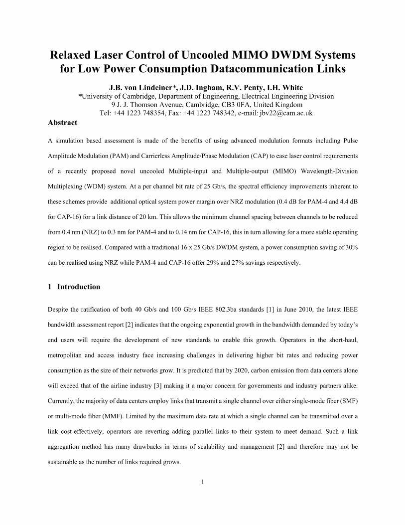
With reference to Fig. 1, which shows an example 4 channel MIMO DWDM system, the principle of the system is
that significant crosstalk between spectral channels is allowed by the large bandwidth of the AWG, but is
accommodated by using signal processing of the six receiver output signals to decode and reconstruct the original
channel signals. To avoid points of singularity, the system uses more receivers than transmitters.
The use of a cyclic AWG allows channels to be detected as they drift outside the overall free spectral range, so that as
in this case, if the channel λ moves beyond the sixth detection channel centered at 300 GHz, it wraps around and is
detected by the first detection channel centered at -200 GHz. Thisallows for multiple frequency bands to be covered
as channels drift. Cyclic channels are shown as dashed lines. Signal processing of detected signals using a minimum
mean square error (MMSE) crosstalk cancellation algorithm shown in Fig. 2, similar to that currently employed in
wireless MIMO systems is used for signal recovery.
Fig. 1 Proposed cyclic AWG profile with overlapping channel spectra
-300 -200 -100 0 100 200 300-60
-50
-40
-30
-20
-10
0
Wavelength Offset from Centre Frequency (GHz)
Po
we
r (d
Bm
)
λ2 λ3 λ4λ1

4
Fig. 2 Schematic diagram of a 4 x 6 uncooled MIMO WDM system
This early MIMO DWDM system allowed for robust operation as channels drifted under the influence of temperature
by reduction of the increased crosstalk from adjacent channels using signal processing at the receiver. Different forms
of signal processing were considered for different scenarios. For example, if the transmitter lasers were integrated on
the same substrate, channels generally drift at a similar rate and so will have relatively constant wavelength spacings
allowing for relatively simple processing to be employed to decode the channels. This scenario cannot however be
assumed, particularly not in the case of discrete laser sources. Here, lasers are often physically separated such that
they experience different environmental temperature variations. This can potentially lead to the situation where two
or more channels drift to coincide with each other and their spectra begins to overlap. For this scenario, signal
processing cannot separate the channels and instead, DC bias tuning is used to vary the emission wavelength of one
or more of the lasers. This forces channel wavelengths apart, reducing crosstalk to an acceptable level and thus making
channel decoding possible. An important criterion for the system design therefore is the minimum wavelength
separation that must be achieved to ensure that decoding can occur. This requirement dependent on the information
bandwidth of the signal as well as if advanced channel filtering such as square-root raised cosine filtering is used.
In this paper, for the first time, simulations are used to determine the improvements that advanced modulation schemes
such PAM-4 and CAP-16 are expected to bring to this system in terms of an improved power budget and more
importantly tuning range, owing to the improved spectral efficiencies of these modulation formats.
The rest of the paper is organized as follows. In Section 3, we review the signal processing principles of the proposed
uncooled MIMO WDM system. Section 4 describes the advantages that CAP offers in terms of link power budget

5
compared with PAM-4 and NRZ. It then describes the potential power consumption savings that may be gained using
the MIMO DWDM approach compared with traditional DWDM Section 5 examines the results of a simulation based
study used to determine how using CAP-16 affects the performance of the system in terms of the minimum allowable
channel separation. Section 6 offers a conclusion to the work.
3 MIMO WDM Signal Processing
The signal processing used for the uncooled MIMO WDM system is similar to that currently employed in wireless
MIMO systems. For an n-channel system that is detected by an m-channel receiver, by treating the AWG output
channels as a linear combination of inputs, the system transfer matrix can be written as:
(1)
where is the m-dimensional receive vector, H is the m by n channel transfer matrix, is the n-dimensional transmit
vector and is the noise vector. In order to recover the originally transmitted symbols, a zero-forcing approach may
be employed. This aims to find a matrix, W, such that WH In, i.e. an n by n identity matrix. A solution to this
equation is known as the Moore-Penrose pseudo inverse [10]:
(2)
For the example 4 channel system of Fig. 2, 6 photodiode outputs may be first captured by an Analogue to Digital
converter (ADC) before being passed to a Field Programmable Gate Array (FPGA) which applies tap weights to the
photodiode outputs. The FPGA is designed to adaptively adjust tap coefficients using a least mean squares algorithm
to find an estimate of W. Once a convergence requirement has been met, tap coefficients are updated allowing crosstalk
to be cancelled as shown in Fig. 2. In practice, because the AWG is designed to have slow roll offs, as lasers drift,
the average powers of the signals from each AWG output vary slowly on environmental change timescales so that
weights only need to be updated on a ~10 ms timescale. Hence, simple electronic tap circuits can be used for decoding
with similar complexity to that found in electronic equalizers currently employed in 10 GbE [11]. The least squares
estimate results in additional penalties comprising both residual crosstalk that isn’t cancelled due to inaccuracies in
the convergence process as well as noise enhancement as shown in Eq. 3.
(3)
6
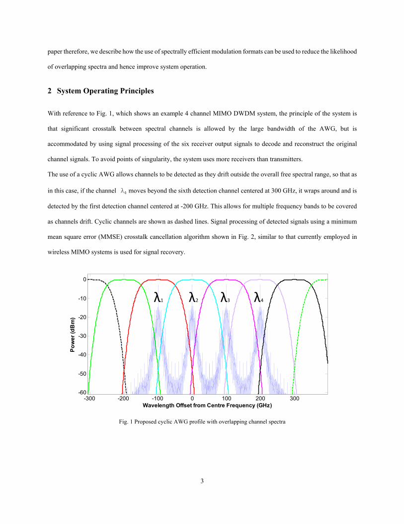
The power penalty associated from this term may be estimated [12] from Eq. 4 as:
10 log
(4)
Fig. 3 shows eye diagrams before and after crosstalk cancellation for a 25 Gb/s NRZ signal assuming a channel spacing
of just 0.5 nm and an AWG bandwidth of 100 GHz. Before crosstalk cancellation, crosstalk is observed, this resulting
in the emergence of a multi-level signal. After crosstalk cancellation, an open eye is observed.
(a) (b)
Fig. 3 Eye diagrams (a) before and (b) after crosstalk cancellation for a 25 Gb/s NRZ signal
4 Carrierless Amplitude and Phase Modulation
CAP is a modulation scheme that is used extensively in Asymmetric Digital Subscriber Line (ADSL) technology. It
is similar to Quadrature Amplitude Modulation (QAM) in that two orthogonal signals are transmitted simultaneously.
The difference between CAP and QAM is that in CAP, the orthogonal signals are generated by manipulation of filter
tap coefficients to generate orthogonal pulse shapes which can then transmit signals with high spectral efficiency [13].
Powerful resilience to dispersion as well as ease of implementation through use of transversal filters as opposed to
high speed mixers makes it an ideal candidate for optical datacommunications. [14, 15]
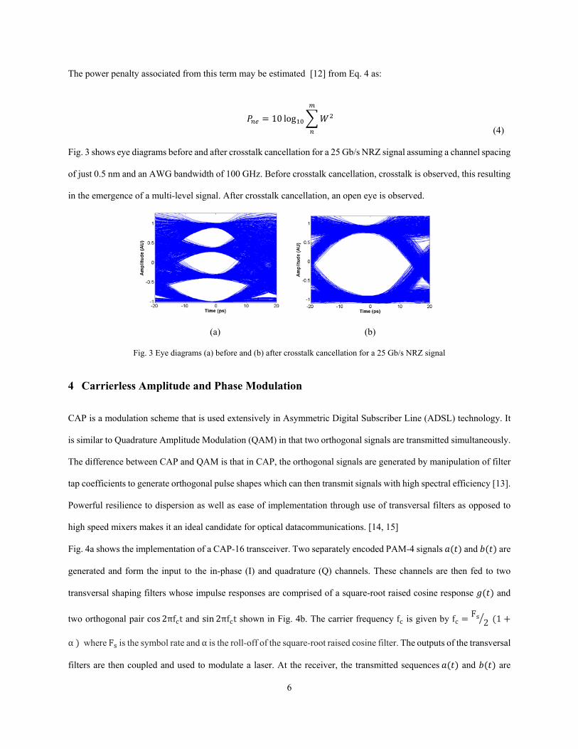
Fig. 4a shows the implementation of a CAP-16 transceiver. Two separately encoded PAM-4 signals and are
generated and form the input to the in-phase (I) and quadrature (Q) channels. These channels are then fed to two
transversal shaping filters whose impulse responses are comprised of a square-root raised cosine response and
two orthogonal pair cos 2πf t and sin 2πf t shown in Fig. 4b. The carrier frequency f is given by f F2 1
α where F is the symbol rate and α is the roll-off of the square-root raised cosine filter. The outputs of the transversal
filters are then coupled and used to modulate a laser. At the receiver, the transmitted sequences and are
7
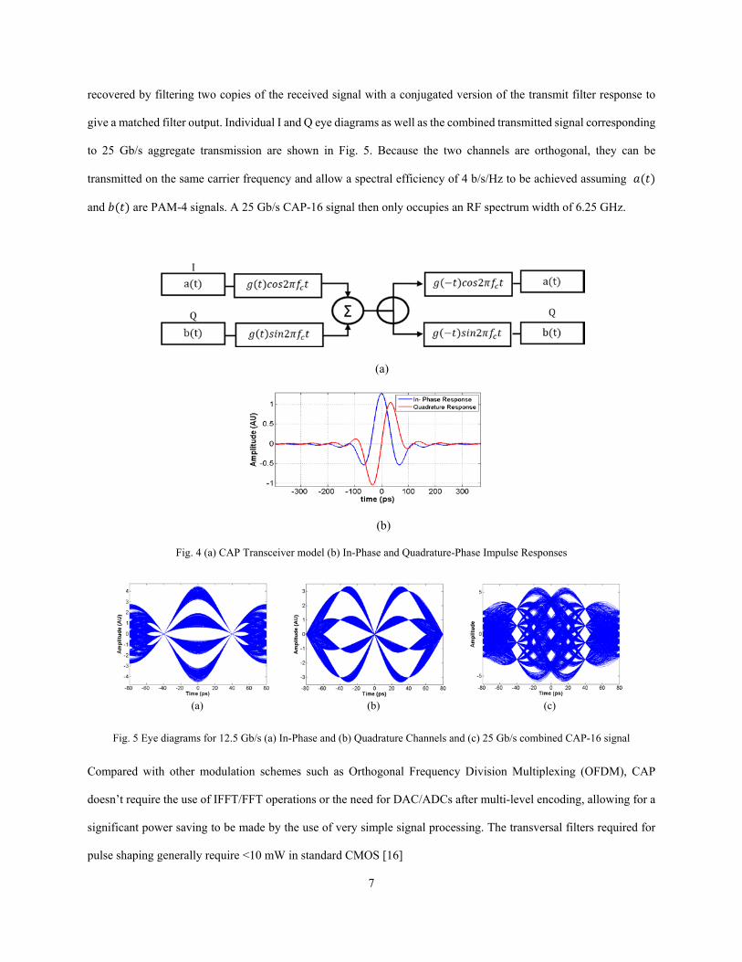
recovered by filtering two copies of the received signal with a conjugated version of the transmit filter response to
give a matched filter output. Individual I and Q eye diagrams as well as the combined transmitted signal corresponding
to 25 Gb/s aggregate transmission are shown in Fig. 5. Because the two channels are orthogonal, they can be
transmitted on the same carrier frequency and allow a spectral efficiency of 4 b/s/Hz to be achieved assuming
and are PAM-4 signals. A 25 Gb/s CAP-16 signal then only occupies an RF spectrum width of 6.25 GHz.
(a)
(b)
Fig. 4 (a) CAP Transceiver model (b) In-Phase and Quadrature-Phase Impulse Responses
(a) (b) (c)
Fig. 5 Eye diagrams for 12.5 Gb/s (a) In-Phase and (b) Quadrature Channels and (c) 25 Gb/s combined CAP-16 signal
Compared with other modulation schemes such as Orthogonal Frequency Division Multiplexing (OFDM), CAP
doesn’t require the use of IFFT/FFT operations or the need for DAC/ADCs after multi-level encoding, allowing for a
significant power saving to be made by the use of very simple signal processing. The transversal filters required for
pulse shaping generally require <10 mW in standard CMOS [16]
8
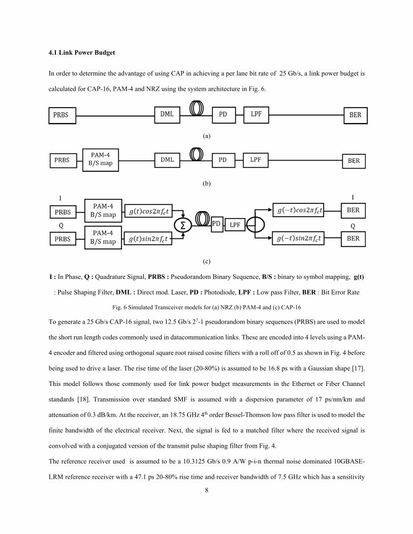
4.1 Link Power Budget
In order to determine the advantage of using CAP in achieving a per lane bit rate of 25 Gb/s, a link power budget is
calculated for CAP-16, PAM-4 and NRZ using the system architecture in Fig. 6.
(a)
(b)
(c)
I : In Phase, Q : Quadrature Signal, PRBS : Pseudorandom Binary Sequence, B/S : binary to symbol mapping, g(t)
: Pulse Shaping Filter, DML : Direct mod. Laser, PD : Photodiode, LPF : Low pass Filter, BER : Bit Error Rate
Fig. 6 Simulated Transceiver models for (a) NRZ (b) PAM-4 and (c) CAP-16
To generate a 25 Gb/s CAP-16 signal, two 12.5 Gb/s 27-1 pseudorandom binary sequences (PRBS) are used to model
the short run length codes commonly used in datacommunication links. These are encoded into 4 levels using a PAM-
4 encoder and filtered using orthogonal square root raised cosine filters with a roll off of 0.5 as shown in Fig. 4 before
being used to drive a laser. The rise time of the laser (20-80%) is assumed to be 16.8 ps with a Gaussian shape [17].
This model follows those commonly used for link power budget measurements in the Ethernet or Fiber Channel
standards [18]. Transmission over standard SMF is assumed with a dispersion parameter of 17 ps/nm/km and
attenuation of 0.3 dB/km. At the receiver, an 18.75 GHz 4th order Bessel-Thomson low pass filter is used to model the
finite bandwidth of the electrical receiver. Next, the signal is fed to a matched filter where the received signal is
convolved with a conjugated version of the transmit pulse shaping filter from Fig. 4.
The reference receiver used is assumed to be a 10.3125 Gb/s 0.9 A/W p-i-n thermal noise dominated 10GBASE-
LRM reference receiver with a 47.1 ps 20-80% rise time and receiver bandwidth of 7.5 GHz which has a sensitivity
9
of -18 dBm at a bit error ratio (BER) of 10-12 [14, 15, 19]. Therefore, assuming a launch power of 0 dBm, a total power
budget of 18 dB can be assumed. The transmitter lasers are assumed to be single mode and so relative intensity noise
(RIN) is neglected for the reference receiver as its contribution is assumed to be negligible [15]. Finally, by varying
the power of the signal after the receiver, the BER at various received powers can be estimated. This is achieved from
measurement of the Q-function which for NRZ is:
12 2
(3)
Where is the thermal noise power at the received power and and represent the 1 and 0 levels for NRZ. The
difference in received power between the 10GBASE-LRM reference receiver and that of the received signal required
to achieve a BER of 10-12 is used to determine the power penalty. For PAM-4, which has 4 level signals as opposed
to just two for NRZ, the signal can be decomposed into 3 different eye openings. Here, the BER for each eye opening
is calculated and the worst BER used to determine a penalty. The same procedure is used for CAP-16, where now
both I and Q channels are first decoded and BERs calculated for both. Here again, the worst-case BER is then used to
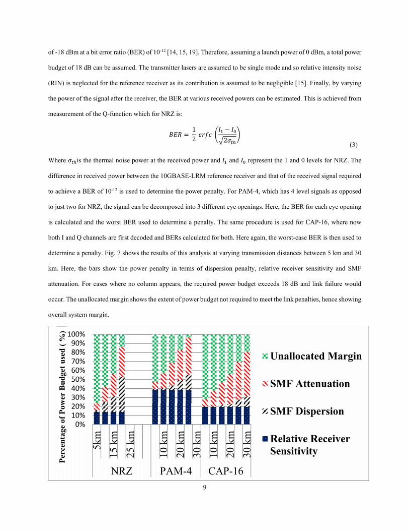
determine a penalty. Fig. 7 shows the results of this analysis at varying transmission distances between 5 km and 30
km. Here, the bars show the power penalty in terms of dispersion penalty, relative receiver sensitivity and SMF
attenuation. For cases where no column appears, the required power budget exceeds 18 dB and link failure would
occur. The unallocated margin shows the extent of power budget not required to meet the link penalties, hence showing
overall system margin.
0%10%20%30%40%50%60%70%80%90%100%
5km
15 k
m
25 k
m
10 k
m
20 k
m
30 k
m
10 k
m
20 k
m
30 k
m
NRZ PAM-4 CAP-16
Unallocated Margin
SMF Attenuation
SMF Dispersion
Relative ReceiverSensitivity
Per
cen
tage
of
Pow
er B
ud
get
use
d (
%)
10
Fig. 7 Single Channel link power budget comparison between 25 Gb/s NRZ, PAM-4 and CAP-16 over SMF of varying length
From the results of Fig.7, some clear conclusions can be drawn as to which modulation format is most appropriate for
certain link distances. Below 10 km with a large unallocated margin, NRZ has the best margin owing to its low relative
receiver sensitivity. The disparity between NRZ and the other schemes arises because it does not suffer from the multi-
level penalties that PAM-4 and CAP-16 suffer from, this being the direct consequence of the slow rise time of the
laser resulting in eye closure. PAM-4 suffers significantly from this compared with CAP-16 because it requires a
switching speed between levels that is twice as fast as CAP-16. Above 10 km, SMF dispersion becomes a significant
limiting factor for NRZ and so PAM-4 and CAP-16 are preferred. This is because the dispersion penalty is dependent
on both the bandwidth of the signal as well as the length of the link. PAM-4 occupies half the bandwidth of NRZ
while CAP-16 occupies only a quarter. This resilience to dispersion makes these schemes very attractive for longer
distance datacommunication applications. Though various algorithms do exist to reduce this penalty [20], these come
at the expense of increased power consumption and receiver complexity
The link power budget does not take into account other penalties such as connector/splitter losses that can be found in
real systems. These can account for roughly 3 dB of penalty which would make NRZ and PAM-4 have insufficient
margin at a link distances in excess of 20 km. Therefore, for systems requiring link distances in excess of 20 km, CAP-
16 is likely to be the only modulation format that can be used in practice.
5 Uncooled MIMO WDM System Aspects
5.1 Minimum Channel Spacing
To demonstrate the advantage of using CAP in allowing MIMO WDM channels to drift more closely together
compared with NRZ and PAM-4, a simulation based study is performed in order to determine the minimum allowable
channel spacing between channels for CAP-16, PAM-4 and NRZ at a per channel bit rate of 25 Gb/s.
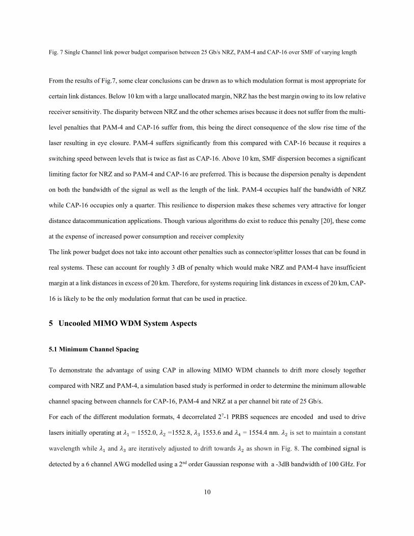
For each of the different modulation formats, 4 decorrelated 27-1 PRBS sequences are encoded and used to drive
lasers initially operating at = 1552.0, =1552.8, 1553.6 and = 1554.4 nm. is set to maintain a constant
wavelength while and are iteratively adjusted to drift towards as shown in Fig. 8. The combined signal is
detected by a 6 channel AWG modelled using a 2nd order Gaussian response with a -3dB bandwidth of 100 GHz. For
11
each of the 4 transmit channels, the 6 outputs of the AWG are fed to 4 crosstalk cancellation units which adaptively
determine the tap weights as outlined in Section 2.
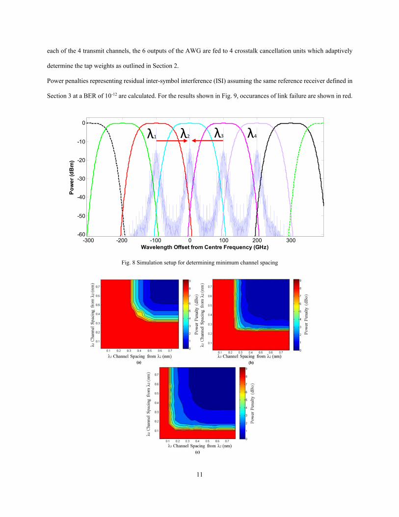
Power penalties representing residual inter-symbol interference (ISI) assuming the same reference receiver defined in
Section 3 at a BER of 10-12 are calculated. For the results shown in Fig. 9, occurances of link failure are shown in red.
Fig. 8 Simulation setup for determining minimum channel spacing
-300 -200 -100 0 100 200 300-60
-50
-40
-30
-20
-10
0
Wavelength Offset from Centre Frequency (GHz)
Po
we
r (d
Bm
)
λ2 λ3 λ4λ1
12
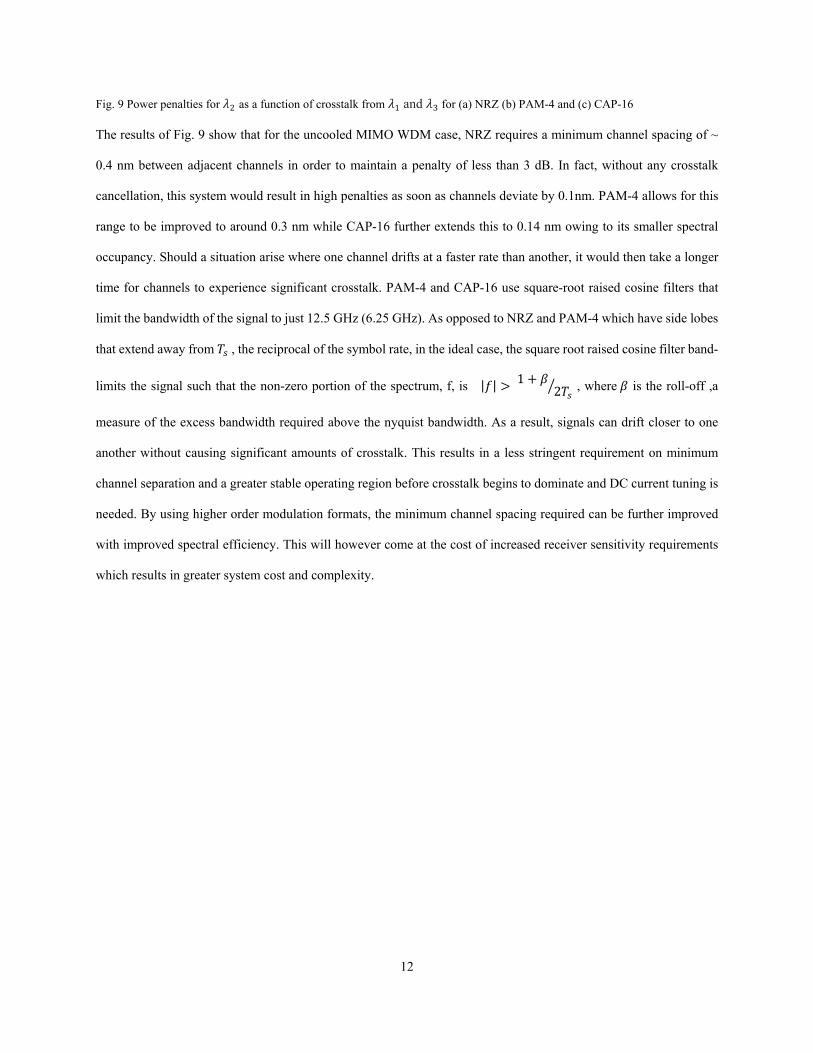
Fig. 9 Power penalties for as a function of crosstalk from and for (a) NRZ (b) PAM-4 and (c) CAP-16
The results of Fig. 9 show that for the uncooled MIMO WDM case, NRZ requires a minimum channel spacing of ~
0.4 nm between adjacent channels in order to maintain a penalty of less than 3 dB. In fact, without any crosstalk
cancellation, this system would result in high penalties as soon as channels deviate by 0.1nm. PAM-4 allows for this
range to be improved to around 0.3 nm while CAP-16 further extends this to 0.14 nm owing to its smaller spectral
occupancy. Should a situation arise where one channel drifts at a faster rate than another, it would then take a longer
time for channels to experience significant crosstalk. PAM-4 and CAP-16 use square-root raised cosine filters that
limit the bandwidth of the signal to just 12.5 GHz (6.25 GHz). As opposed to NRZ and PAM-4 which have side lobes
that extend away from , the reciprocal of the symbol rate, in the ideal case, the square root raised cosine filter band-
limits the signal such that the non-zero portion of the spectrum, f, is | | 1 2 , where is the roll-off ,a
measure of the excess bandwidth required above the nyquist bandwidth. As a result, signals can drift closer to one
another without causing significant amounts of crosstalk. This results in a less stringent requirement on minimum
channel separation and a greater stable operating region before crosstalk begins to dominate and DC current tuning is
needed. By using higher order modulation formats, the minimum channel spacing required can be further improved
with improved spectral efficiency. This will however come at the cost of increased receiver sensitivity requirements
which results in greater system cost and complexity.
13
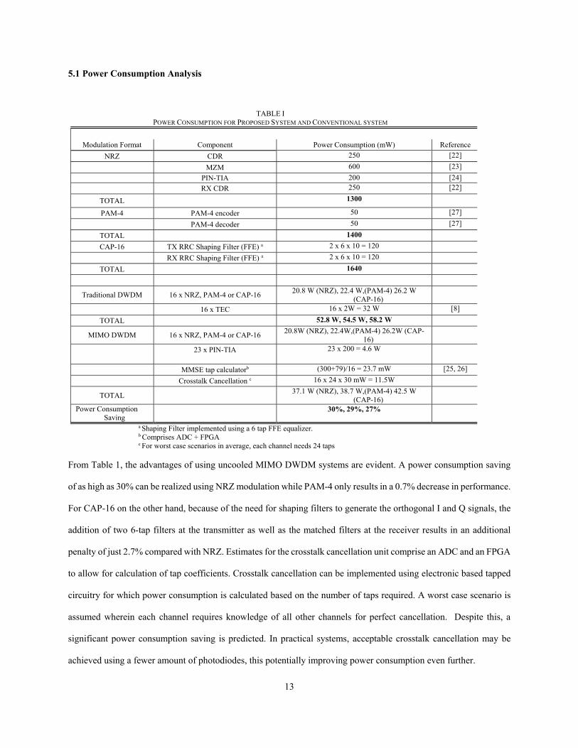
5.1 Power Consumption Analysis
From Table 1, the advantages of using uncooled MIMO DWDM systems are evident. A power consumption saving
of as high as 30% can be realized using NRZ modulation while PAM-4 only results in a 0.7% decrease in performance.
For CAP-16 on the other hand, because of the need for shaping filters to generate the orthogonal I and Q signals, the
addition of two 6-tap filters at the transmitter as well as the matched filters at the receiver results in an additional
penalty of just 2.7% compared with NRZ. Estimates for the crosstalk cancellation unit comprise an ADC and an FPGA
to allow for calculation of tap coefficients. Crosstalk cancellation can be implemented using electronic based tapped
circuitry for which power consumption is calculated based on the number of taps required. A worst case scenario is
assumed wherein each channel requires knowledge of all other channels for perfect cancellation. Despite this, a
significant power consumption saving is predicted. In practical systems, acceptable crosstalk cancellation may be
achieved using a fewer amount of photodiodes, this potentially improving power consumption even further.
TABLE I POWER CONSUMPTION FOR PROPOSED SYSTEM AND CONVENTIONAL SYSTEM
Modulation Format Component Power Consumption (mW) Reference
NRZ CDR 250 [22]
MZM 600 [23]
PIN-TIA 200 [24] RX CDR 250 [22]
TOTAL 1300
PAM-4 PAM-4 encoder 50 [27]
PAM-4 decoder 50 [27]
TOTAL 1400
CAP-16 TX RRC Shaping Filter (FFE) a 2 x 6 x 10 = 120
RX RRC Shaping Filter (FFE) a 2 x 6 x 10 = 120
TOTAL 1640
Traditional DWDM 16 x NRZ, PAM-4 or CAP-16 20.8 W (NRZ), 22.4 W,(PAM-4) 26.2 W
(CAP-16)
16 x TEC 16 x 2W = 32 W [8]
TOTAL 52.8 W, 54.5 W, 58.2 W
MIMO DWDM 16 x NRZ, PAM-4 or CAP-16 20.8W (NRZ), 22.4W,(PAM-4) 26.2W (CAP-
16)
23 x PIN-TIA
23 x 200 = 4.6 W
MMSE tap calculatorb (300+79)/16 = 23.7 mW [25, 26]
Crosstalk Cancellation c 16 x 24 x 30 mW = 11.5W
TOTAL 37.1 W (NRZ), 38.7 W,(PAM-4) 42.5 W
(CAP-16)
Power Consumption Saving
30%, 29%, 27%
a Shaping Filter implemented using a 6 tap FFE equalizer. b Comprises ADC + FPGA c For worst case scenarios in average, each channel needs 24 taps
14
6 Conclusion
We have reviewed a new uncooled MIMO WDM system that can be implemented using standard components for low
cost datacommunication links. The system can operate uncooled without use of a TEC and uses a modified AWG
profile with an overlapping channel structure to allow channels to be detected as they drift under temperature. Using
an MMSE crosstalk cancellation unit, channels can still be detected at very close channel spacings. CAP-16 has been
identified as being an excellent candidate for such a system owing to its ease of implementation and improved spectral
efficiency compared with NRZ and PAM-4. A reduction in symbol rate and the resulting improved resilience to
dispersion, allows for an improved minimum required channel spacing, with 25 Gb/s CAP-16 requiring a minimum
channel spacing of just 0.14 nm compared to PAM-4 (0.3 nm) and NRZ (0.4 nm). In addition, owing to the reduced
symbol rate of these schemes, laser drive currents can be reduced, allowing enhanced headroom for wavelength tuning
to be realized. In terms of power consumption, an improvement of 30% can be realized using NRZ modulation with
PAM-4 and CAP-16 offering a 29% and 27% improvement respectively.
7 Acknowledgments
The authors would like to acknowledge the support of the UK Engineering and Physical Research Council.
[1] IEEE 802.3ba, "40 Gb/s and 100 Gb/s Ethernet," 2010.
[2] D. J Law, W. W. Diab, A. Healey, S. B. Carlson, V. Maguire,, "IEEE 802.3 Industry Connections Ethernet Bandwidth Assessment," 19 July 2012. [Online]. Available: http://www.ieee802.org/3/ad_hoc/bwa/BWA_Report.pdf.
[3] G. Boccaletti, M. Löffler, and J. M. Oppenheim, "How IT can cut carbon emissions," McKinsey Quarterly, 2008.
[4] J. Lee, N. Kaneda, T. Pfau, A. Konczykowska, F. Jorge, J. Dupuy and Y. Chen, "Serial 103.125-Gb/s Transmission over 1 km SSMF for Low-Cost, Short-Reach Optical Interconnects," in OFC, San Francisco, 2014.
[5] J D. Ingham, R. V. Penty, I. H. White, and D. G. Cunningham, "100 Gb/s PAM4-CAP2 Real-Time Modulation of a Single Optical Source for Next-Generation Datacommunication Links," in Optical Fiber Communication Conference (OFC), San Francisco, 2014.
[6] C.A. Brackett, "Dense wavelength division multiplexing networks:Principles and applications," IEEE J. Select. Areas Commun., vol. 8, p. 948, 1990.
[7] D. Minoli, Enterprise Architecture A to Z - Frameworks, Business Process Modeling, SOA and Infrastructure Technology, Boca Raton: Auerbach, 2008.
[8] J. J. Lee, H. S. Kang, and J. S. Koh, "Predication of TEC Power Consumption for Cooled Laser Diode Module," in LEOS, 2004.
[9] J. D. Ingham, S. H. Lee, R. V. Penty, I. H. White and D. G. Cunningham, "100 Gb/s uncooled WDM system using conventional WDM components and advanced receiver signal processing," in ECOC, Amsterdam, 2012.

15
[10] R.A. Horn and C.R. Johnson, Matrix Analysis, Cambridge: Cambridge Univ. Press, 1985.
[11] Xia, C. Ajgaonkar, M.; Rosenkranz, W, "On the Performance of the Electrical Equalization Technique in MMF Links for 10-Gigabit Ethernet," Journal of Lightwave Technology, vol. 23, no. 6, pp. 2001-2011, 2005.
[12] S. H. Lee, D. G. Cunningham, R.V. Penty, I. H. White, "Uncooled MIMO WDM system using advanced receiver signal processing techniques," in SPIE Photonic West , San Francisco, 2012.
[13] J.J. Werner, "Tutorial on Carrierless AM/PM - Part III," in ANSI X3T9.5 TPlPMD working group, 1993.
[14] J. D. Ingham, R. V. Penty, and I. H. White, "40 Gb/s carrierless amplitude and phase modulation for low-cost optical data communication links," in OFC/NFOEC, Los Angeles, 2011,.
[15] J.L. Wei, D.G. Cunningham, R.V. Penty, I.H.White, "Study of 100 Gigabit Ethernet Using Carrierless Amplitude/Phase Modulation and Optical OFDM," Journal of Lightwave Technology, vol. 31, no. 9, pp. 1367-1373, 2013.
[16] C. L. Schow et al., "Transmitter Pre-Distortion for Simultaneous Improvements in Bit-Rate, Sensitivity, Jitter, and Power Efficiency in 20 Gb/s CMOS-driven VCSEL Links," in OFC/NFOEC, Los Angeles, 2011.
[17] G. D. Brown, "Bandwidth and Rise Time Calculations for Digital Multimode Fibre-Optic Data Links," Journal of Lightwave Technology, vol. 10, no. 5, pp. 672-678, 1992.
[18] "Fibre Channel—Methodologies for Signal Quality Specification (FCMSQS)," International Committee for Information Technology Standards, 2011.
[19] I. H. White, J. D. Ingham, and R. V. Penty, "Systems aspects of optical technologies for use in data communications," in OFC/NFOEC, Los Angeles, 2011.
[20] H. S. Carrer, D. E. Crivelli and M. R. Hueda, "Maximum likelihood sequence estimation receivers for DWDM lightwave systems," in Proc. IEEE Globecom, 2004.
[21] J. D’Ambrosia, "100 Gigabit Ethernet and Beyond," IEEE Commun. Mag, vol. 48, no. 3, pp. S6-S13, 2010.
[22] J. King et. al, "MMF links, EQ and FEC," in IEEE 802.3 Plenary Meeting, Atlanta, 2011.
[23] S. Bhoja et. al, "Study of PAM modulation for 100GE over a single laser," in IEEE 802.3 Interim Meeting, 2012.
[24] R.S Tucker, "Green Optical Communicatios - Part I: Energy Limitations in Transport," IEEE J. Sel. Topics Quantum Electron.,, vol. 17, no. 2, pp. 245-260, 2011.
[25] E. Z. Tabasy et. al, "A 6b 10 GS/s TI-SAR ADC with embedded 2-tap FFE/1-tap DFE in 65 nm CMOS," in VLSI Circuits (VLSIC), Kyoto, 2013.
[26] Xilinx Inc., "Power Efficiency for Xilinx 7 series," [Online]. Available: http://www.xilinx.com/products/technology/power/index.htm.
[27] J. Lee et. al, "Design and Comparison of Three 20-Gb/s Backplane Transceivers for Duobinary, PAM4, and NRZ Data," IEEE Journal of Solid-State Circuits, vol. 43, no. 9, pp. 2120 - 2133, 2008.