Embed Size (px)
Citation preview
Relays
Relays are great tools for turning on and off entire circuits, either with a small control switch, or with a microcontroller like the Arduino. To understand how relays are useful and how to control them, First, we need to understand that there are many types of switches.
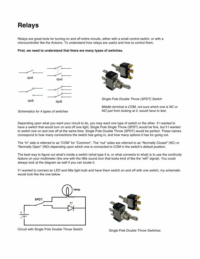
Schematics for 4 types of switches
Single Pole Double Throw (SPDT) Switch Middle terminal is COM, not sure which one is NC or NO just from looking at it, would have to test.
Depending upon what you want your circuit to do, you may want one type of switch or the other. If I wanted to have a switch that would turn on and off one light, Single Pole Single Throw (SPST) would be fine, but if I wanted to switch one on and one off at the same time. Single Pole Double Throw (SPDT) would be perfect. These names correspond to how many connections the switch has going in, and how many options it has for going out. The “in” side is referred to as “COM” for “Common”. The “out” sides are referred to as “Normally Closed” (NC) or “Normally Open” (NO) depending upon which one is connected to COM in the switch’s default position. The best way to figure out what’s inside a switch (what type it is, or what connects to what) is to use the continuity feature on your multimeter (the one with the little sound icon that looks kind of like the “wifi” signal). You could always look at the diagram as well if you can locate it. If I wanted to connect an LED and little light bulb and have them switch on and off with one switch, my schematic would look like the one below.
Circuit with Single Pole Double Throw Switch
Single Pole Double Throw Switches
Relays A relay is a combination of coil and at least one switch. The switch moves when the coil has power running through it. This allows you to control the switch without making any physical contact with it. When the coil is powered up, it creates a magnetic field around it that pulls the switch from one position to another with its magnetism. When the power is removed from the coil, the field dissipates and the switch springs back to its original position.
Same diagram as Page 1, except now we have coils
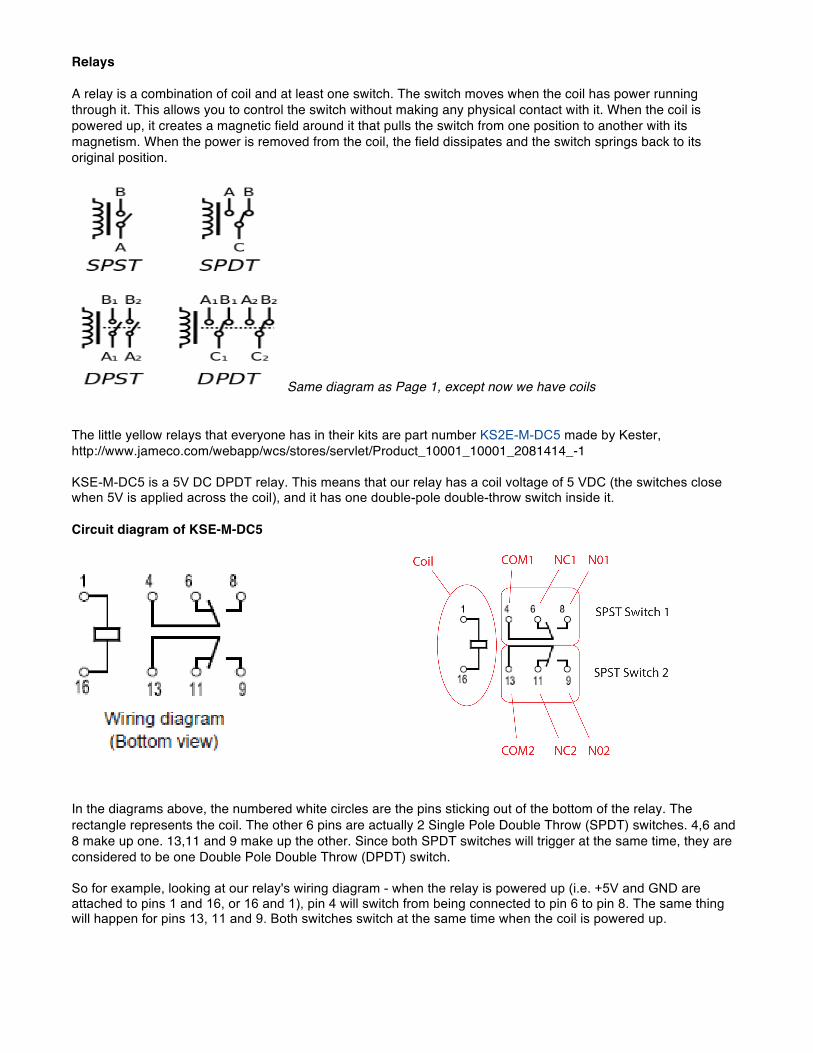
The little yellow relays that everyone has in their kits are part number KS2E-M-DC5 made by Kester, http://www.jameco.com/webapp/wcs/stores/servlet/Product_10001_10001_2081414_-1 KSE-M-DC5 is a 5V DC DPDT relay. This means that our relay has a coil voltage of 5 VDC (the switches close when 5V is applied across the coil), and it has one double-pole double-throw switch inside it.
Circuit diagram of KSE-M-DC5
In the diagrams above, the numbered white circles are the pins sticking out of the bottom of the relay. The rectangle represents the coil. The other 6 pins are actually 2 Single Pole Double Throw (SPDT) switches. 4,6 and 8 make up one. 13,11 and 9 make up the other. Since both SPDT switches will trigger at the same time, they are considered to be one Double Pole Double Throw (DPDT) switch. So for example, looking at our relay's wiring diagram - when the relay is powered up (i.e. +5V and GND are attached to pins 1 and 16, or 16 and 1), pin 4 will switch from being connected to pin 6 to pin 8. The same thing will happen for pins 13, 11 and 9. Both switches switch at the same time when the coil is powered up.
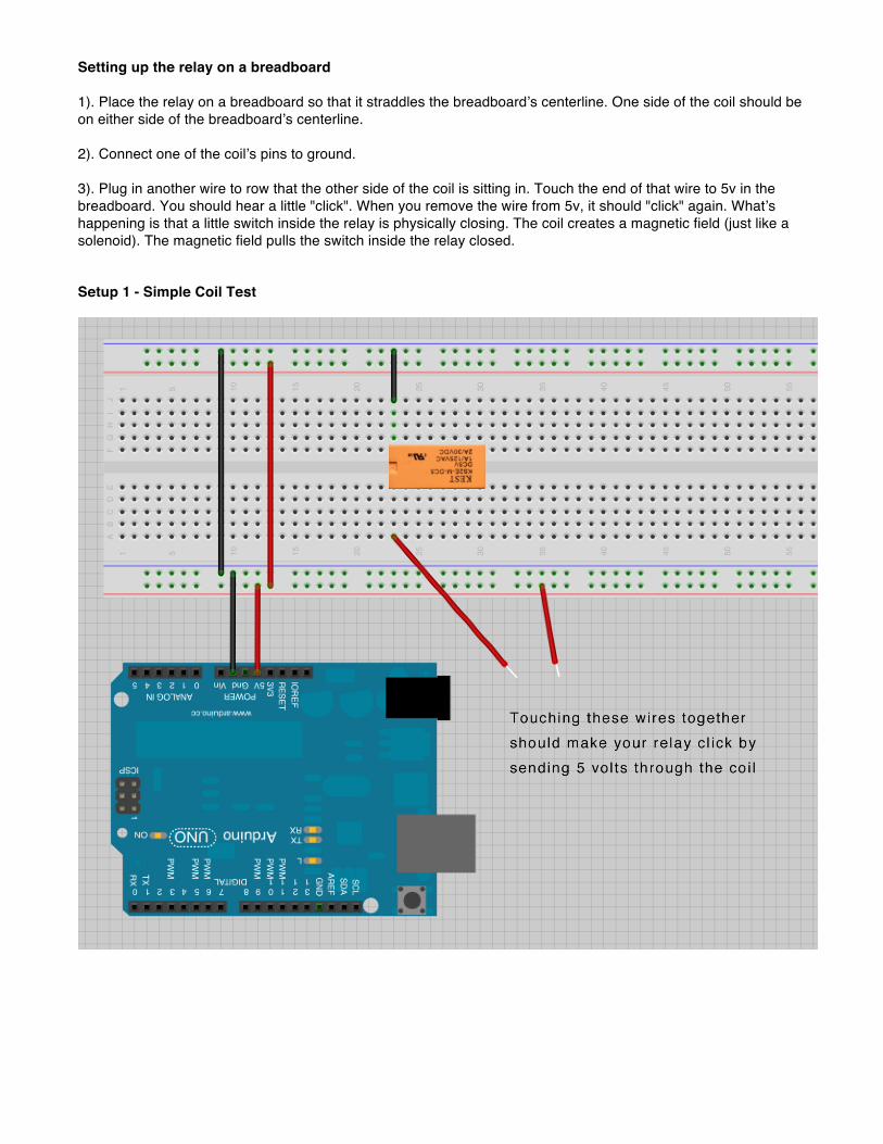
Setting up the relay on a breadboard 1). Place the relay on a breadboard so that it straddles the breadboard’s centerline. One side of the coil should be on either side of the breadboard’s centerline.
2). Connect one of the coil’s pins to ground. 3). Plug in another wire to row that the other side of the coil is sitting in. Touch the end of that wire to 5v in the breadboard. You should hear a little "click". When you remove the wire from 5v, it should "click" again. What’s happening is that a little switch inside the relay is physically closing. The coil creates a magnetic field (just like a solenoid). The magnetic field pulls the switch inside the relay closed. Setup 1 - Simple Coil Test
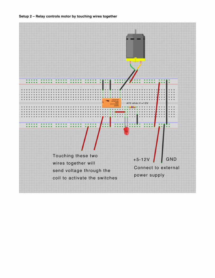
Setup 2 – Relay controls motor by touching wires together
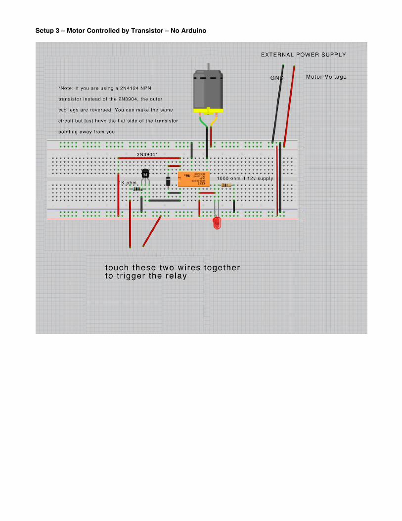
Setup 3 – Motor Controlled by Transistor – No Arduino
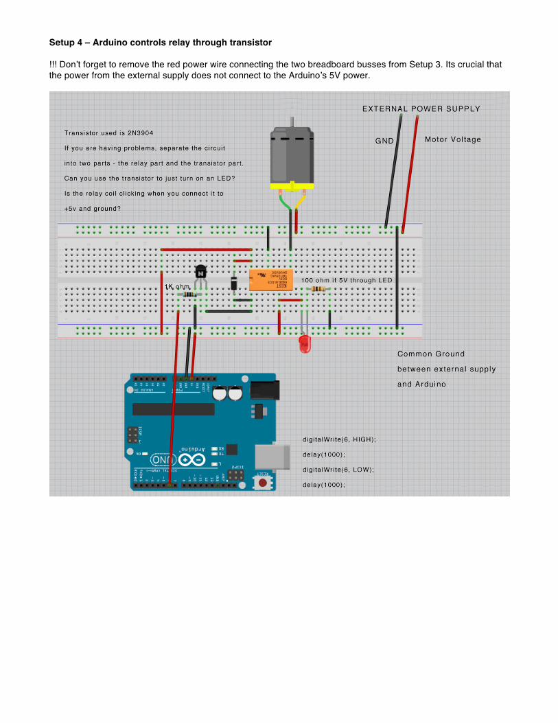
Setup 4 – Arduino controls relay through transistor !!! Don’t forget to remove the red power wire connecting the two breadboard busses from Setup 3. Its crucial that the power from the external supply does not connect to the Arduino’s 5V power.