Embed Size (px)
Citation preview
Copyright © 2014 Juniper Networks, Inc. Copyright © 2014 Juniper Networks, Inc.
RELIABILITY AND NFV
BRIAN LEVY CTO SP SECTOR EMEA
THE ETSI NFV FOUNDATION ARCHITECTURE
Juniper is an active supporter of the ETSI Network Functions Virtualisation Initiative. We recently hosted the forums plenary meeting in our campus in Sunnyvale with over 350 attendees from 155 companies attending. Juniper is providing regular technical contributions to the forum and working with the industry to develop the architectural framework for the future The next slides cover the foundation architecture being defined by the forum and the key stages of the virtualised network functions lifecycle
ETSI NFV REFERENCE ARCHITECTURE OVERVIEW
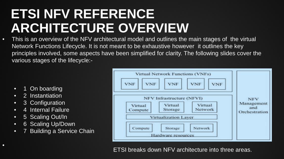
• This is an overview of the NFV architectural model and outlines the main stages of the virtual Network Functions Lifecycle. It is not meant to be exhaustive however it outlines the key principles involved, some aspects have been simplified for clarity. The following slides cover the various stages of the lifecycle:-
• 1 On boarding • 2 Instantiation • 3 Configuration • 4 Internal Failure • 5 Scaling Out/In • 6 Scaling Up/Down • 7 Building a Service Chain
•
ETSI breaks down NFV architecture into three areas.
1. ON BOARDING
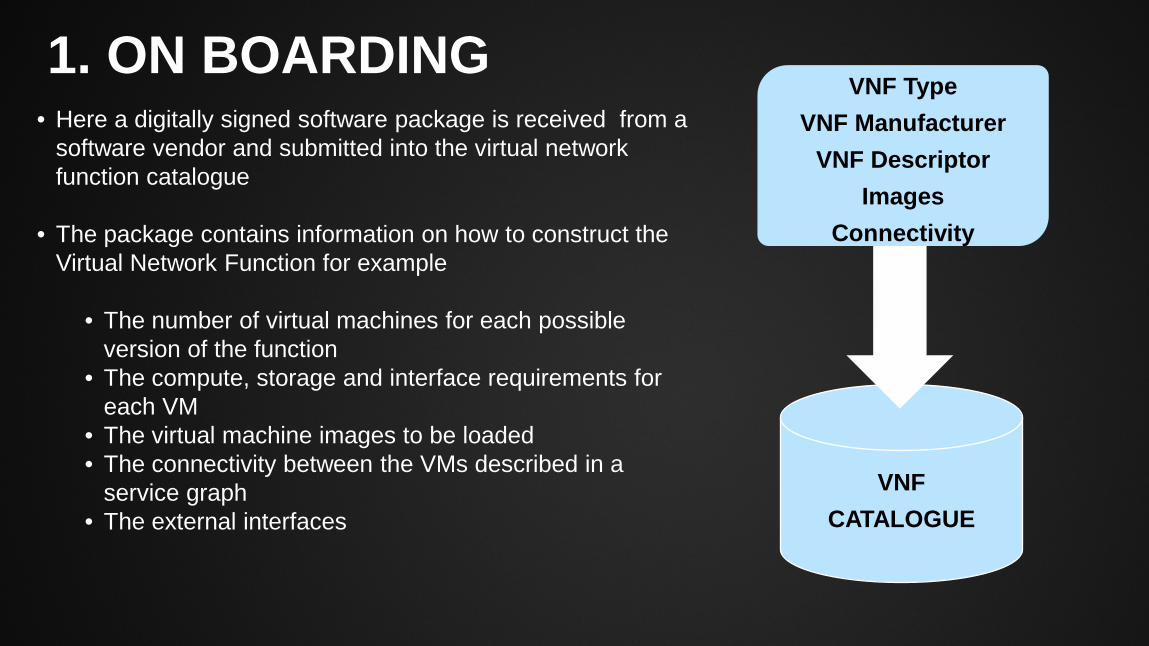
• Here a digitally signed software package is received from a software vendor and submitted into the virtual network function catalogue
• The package contains information on how to construct the Virtual Network Function for example
• The number of virtual machines for each possible version of the function
• The compute, storage and interface requirements for each VM
• The virtual machine images to be loaded • The connectivity between the VMs described in a
service graph • The external interfaces
VNF CATALOGUE
VNF Type VNF Manufacturer
VNF Descriptor Images
Connectivity
2. INSTANTIATION
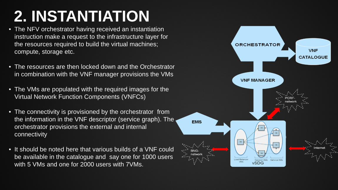
• The NFV orchestrator having received an instantiation instruction make a request to the infrastructure layer for the resources required to build the virtual machines; compute, storage etc.
• The resources are then locked down and the Orchestrator in combination with the VNF manager provisions the VMs
• The VMs are populated with the required images for the Virtual Network Function Components (VNFCs)
• The connectivity is provisioned by the orchestrator from the information in the VNF descriptor (service graph). The orchestrator provisions the external and internal connectivity
• It should be noted here that various builds of a VNF could be available in the catalogue and say one for 1000 users with 5 VMs and one for 2000 users with 7VMs.
3. CONFIGURATION
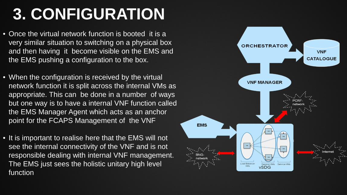
• Once the virtual network function is booted it is a very similar situation to switching on a physical box and then having it become visible on the EMS and the EMS pushing a configuration to the box.
• When the configuration is received by the virtual network function it is split across the internal VMs as appropriate. This can be done in a number of ways but one way is to have a internal VNF function called the EMS Manager Agent which acts as an anchor point for the FCAPS Management of the VNF
• It is important to realise here that the EMS will not see the internal connectivity of the VNF and is not responsible dealing with internal VNF management. The EMS just sees the holistic unitary high level function
4. INTERNAL FAILURE
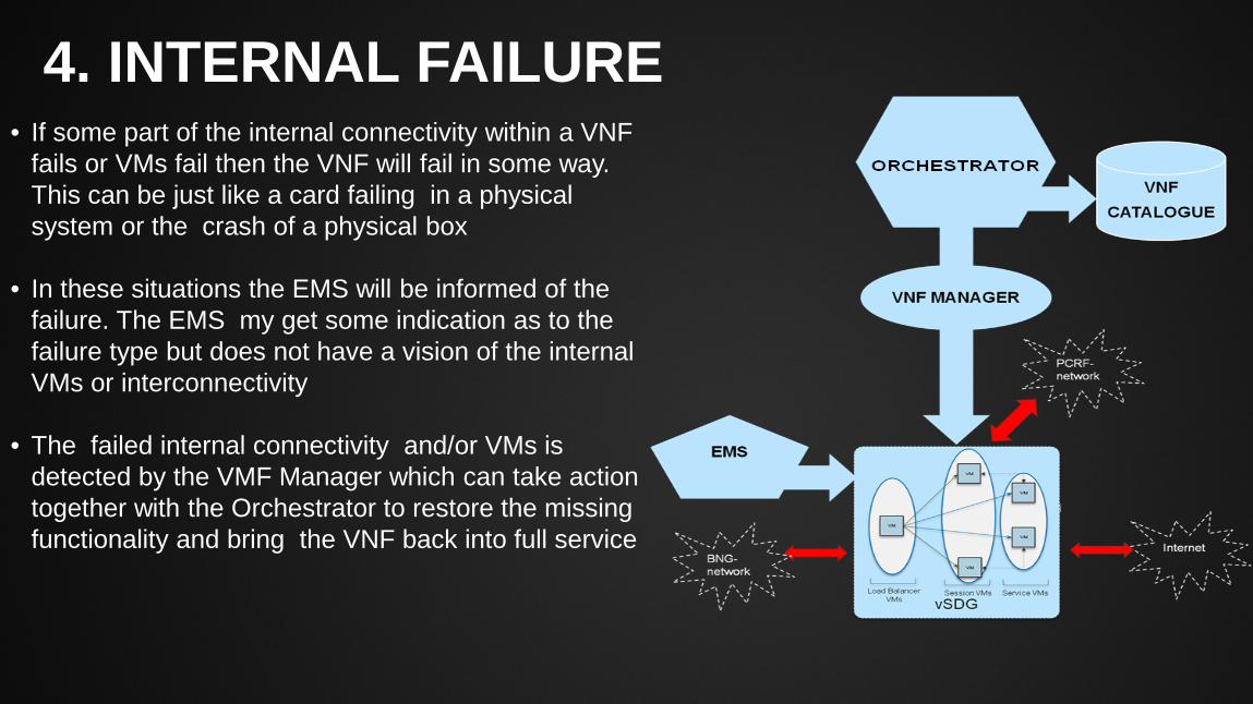
• If some part of the internal connectivity within a VNF fails or VMs fail then the VNF will fail in some way. This can be just like a card failing in a physical system or the crash of a physical box
• In these situations the EMS will be informed of the failure. The EMS my get some indication as to the failure type but does not have a vision of the internal VMs or interconnectivity
• The failed internal connectivity and/or VMs is detected by the VMF Manager which can take action together with the Orchestrator to restore the missing functionality and bring the VNF back into full service
5. SCALE OUT/IN
SGW chassis
vSDG
VM
VM
VM
VM
VM
Load Balancer VMs Session VMs Service VMs
Internet
PCRF- network
BNG- network
VM VM
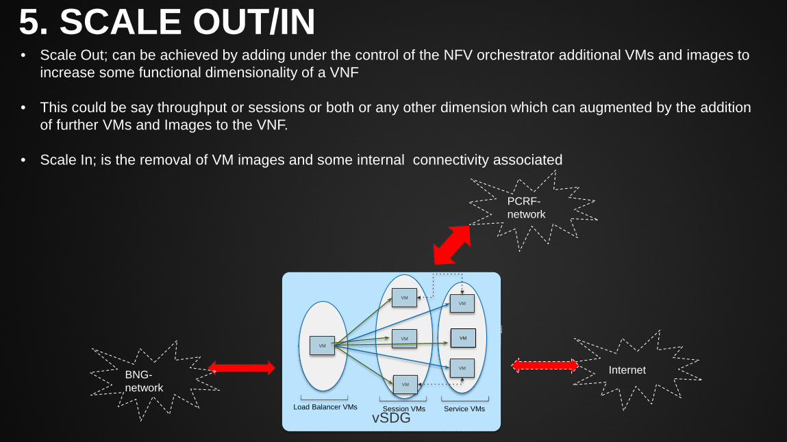
• Scale Out; can be achieved by adding under the control of the NFV orchestrator additional VMs and images to increase some functional dimensionality of a VNF
• This could be say throughput or sessions or both or any other dimension which can augmented by the addition
of further VMs and Images to the VNF.
• Scale In; is the removal of VM images and some internal connectivity associated
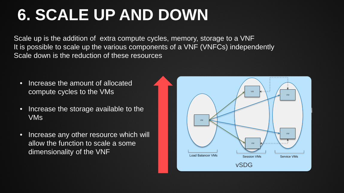
6. SCALE UP AND DOWN
Scale up is the addition of extra compute cycles, memory, storage to a VNF It is possible to scale up the various components of a VNF (VNFCs) independently Scale down is the reduction of these resources
SGW chassis
vSDG
VM
VM
VM
VM
VM
Load Balancer VMs Session VMs Service VMs
• Increase the amount of allocated compute cycles to the VMs
• Increase the storage available to the VMs
• Increase any other resource which will allow the function to scale a some dimensionality of the VNF
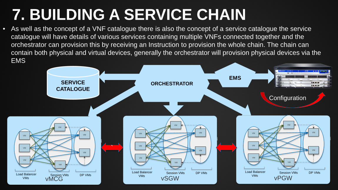
7. BUILDING A SERVICE CHAIN
• As well as the concept of a VNF catalogue there is also the concept of a service catalogue the service catalogue will have details of various services containing multiple VNFs connected together and the orchestrator can provision this by receiving an Instruction to provision the whole chain. The chain can contain both physical and virtual devices, generally the orchestrator will provision physical devices via the EMS
SERVICE CATALOGUE
ORCHESTRATOR
SGW chassis
vMCG
VM
VM
VM
VM
VM
VM
VM
Load Balancer VMs
Session VMs DP VMs
SGW chassis
vSGW
VM
VM
VM
VM
VM
VM
VM
Load Balancer VMs
Session VMs DP VMs
SGW chassis
vPGW
VM
VM
VM
VM
VM
VM
VM
Load Balancer VMs
Session VMs DP VMs
`
EMS
Configuration
NFV SPLITS THE MANAGEMENT PLANE In the NFV architecture we are splitting the management plane, the VNF manager being responsible for the FCAPS of the internal VNF operations and its external FCAPS being managed by the EMS. This has the following advantages:-
1. Minimal changes are required to the existing EMS which will see virtual functions much the same as physical functions
2. The VNF manager is responsible for the internal management of a virtual function and plays a key role in internal fault management and self healing processes
3. The VNF manger must be highly resilient if it fails then further internal failures cannot be repaired and functions like scale out/in cannot operate
4. The cadence of the VNF manager to VNF relationship is not defined in the ETSI standard it can be 1:1 with a function if required and can be provided by the VNF vendor
It should be noted though that the NFV architecture allows for self healing capabilities that go well beyond what is available with physical functions today
OVERALL SYSTEM RELIABILITY
In traditional networks of today we build in resiliency often by diversity. Diversity of path, diversity of equipment. We want to ensure that the failure of the total network (system) is minimised. With NFV we have a consistent platform architecture which hosts the various network functions. Faults within the platform architecture could span many even all functions and the chances of a catastrophic failure could be higher than with a traditional physical network infrastructure There are things that we can do make the platform architecture highly resilient however it is a more closely coupled system with greater statistical coherence so the basic probability of a total platform failure – during say an upgrade or fault condition could be much higher than in a traditional physical network. This can be minimised but a deal of thought is needed to address
VNF RUN TIME ISSUES When we deploy a new VNF we use the VNF descriptor as the “recipe” telling us what Virtual Machines to deploy , what images to load etc. Associated with this recipe is a run time descriptor which informers the orchestrator as to the geographic rules for deployment examples of which could be:- 1. All Virtual Network Function Components (VNFCs) may be on the same processor 2. No Virtual network Function Components (VNFCs) may be on the same processor 3. Any processor cluster is allowed 4. Same processor cluster only 5. Same node 6. Anywhere
Obvious the issues here are not just about reliability but also about performance, some types of VNFC connections (serial port and shared memory) require same processor geography When constructing the software within a VNF it is open to the vendor to decide on how re-sync will take place in the case of the partial failure of a function
RESILIENCY AT DIFFERENT LEVELS OF ABSTRACTION
As well as building residency into a VNF function we can build resiliency into service chains (service chains being groups of VNFs joined together to support a service We can build a service chain with parallel branches say with a load balancer between them. In this case if a total function fails in one branch, the parallel branch can take over Load balancers can be used within network functions, between network functions or even in the infrastructure level. The dynamic nature of NFV offers new possibilities for protection such as the ability to create a new service chain on demand maybe over a difference physical infrasture and to off-load to this. We are truly in a new world and are now longer bound by a fixed a siloed infrastructure Dynamic Scale-Out of functions can be used to mitigate unplanned failures
INFRASTRUCTURE RESILIENCY The NFV platform of course runs on a physical infrastructure of servers storage and hypervisors virtual functions can dynamically move across this infrastructure which can be diverse Root cause analysis of failures in the virtual layer of the architecture can be difficult to correlate to the physical layer and there is a danger that new functions could be mapped constantly to a failed piece of hardware and then remapped until they work. We need to be able to indentify hardware failures with correlation to the virtualised functions which run on them. Virtualised resiliency models at the software layer do not obviate the need for hardware reliability but can mask failures at the service level We have to consider infrastructure resiliency all the way from the physical right up to the hypervisor layer . A serious bug in the hypervisor layer could cause multiple failures of functions across the infrastructure for example
SUMMARY The ETSI NFV architecture represents a true paradigm shift in the way network functions are actualised It offers new residency capabilities and flexibility, however with that comes an infrastructure that is more tightly bound architecturally and we need to taking account for this as we design for reliability We need to build in appropriate reliance at all levels of abstraction from the physical to the virtual We have far more flexibility that ever before and need to be careful not to increase the operational complexity here Key will be automation it just simply will not be possible to manage such an infrastructure any other way I hope these slides have provided a flavour on both the opportunity and challenges we will face