Embed Size (px)
Citation preview

RELIABILITY, AVAILABILITY, MAINTAINABILITY,
AND COST (RAM-C) RATIONALE REPORT
OUTLINE GUIDANCE
Version 1.0
February 28, 2017
Office of the Deputy Assistant Secretary of Defense for Systems Engineering
Washington, D.C.
Distribution Statement A. Cleared by DOPSR, Case # 17-S-1312. Distribution is unlimited.
The following RAM-C Report outline was prepared by the Office of the Deputy Assistant Secretary of
Defense for Systems Engineering for use by Department of Defense acquisition programs. The outline
includes guidance and expectations regarding appropriate details to include in each section.
The program may use this document as a template or establish a RAM-C Report template that includes
the recommended content.
Please direct questions or comments to the Office of Primary Responsibility:
Deputy Assistant Secretary of Defense
Systems Engineering
3030 Defense Pentagon
3C167
Washington, DC. 20301-3030
E-mail: [email protected]
http://www.acq.osd.mil/se/
Distribution Statement A. Cleared by DOPSR, Case # 17-S-1312. Distribution is unlimited.
Program Name RAM-C Report.
UNCLASSIFIED / Distribution Statement if Applicable
1
Reliability, Availability, Maintainability, and Cost (RAM-C)
Rationale Report
Month dd, yyyy
Program Name – ACAT Level
RAM-C Rationale Report
Version ___
Attached To Program Name System Engineering Plan
Supporting Milestone _
and
[Appropriate Phase Name]
SEP Dated Month dd, yyyy, SEP Version Xx
******************************************************************
*******************
Program Name RAM-C Report.
UNCLASSIFIED / Distribution Statement if Applicable
2
SUBMITTED BY
__________________________
Name
Lead Systems Engineer
____________
Date
__________________________
Name
Product Support Manager
____________
Date
__________________________
Name
Business Financial Manager
____________
Date
__________________________
Name
Program Manager
____________
Date
CONCURRENCE
__________________________
Name
Program Executive Officer or
Equivalent
____________
Date
COMPONENT APPROVAL
__________________________
Name
Title, Office
____________
Date
Expectation: The RAM-C Rationale Report should be attached to the SEP and approved at an
appropriate level as determined by the program office.
Program Name RAM-C Report.
UNCLASSIFIED / Distribution Statement if Applicable
3
Contents
1. Executive Summary
1.1. Sustainment KPP Assessment
1.2. Summary
2. Introduction
2.1. Purpose
2.2. Changes
2.3. Preparers
3. Program Information
3.1. System Description
3.2. Sustainment Parameters
3.3. OMS/MP
3.4. Maintenance Concept and Planning Factors
4. Validation
4.1. Operational Availability (AO)
4.2. Materiel Availability (AM)
4.3. Reliability
4.4. O&S Cost
4.5. Summary
5. Feasibility
5.1. Composite System Model
5.2. R&M Feasibility
5.3. O&S Cost Feasibility
5.4. AO and AM Feasibility
5.5. Feasibility Summary
6. Trade Studies
7. Summary
Annex A – Acronyms
Annex B – Documentation, References, and Tools
Annex C – Composite Model Details
Program Name RAM-C Report.
UNCLASSIFIED / Distribution Statement if Applicable
4
Tables
Table 1.1-1 Sustainment KPPs
Table 2.2-1 RAM-C Update Record
Table 2.3-1 RAM-C Preparers and Organizations
Table 3.2-1 Sustainment Parameters
Table 3.3-1 Operational Mode Summary
Table 3.3-2 Summary of Environmental Data
Table 4.1-1 AO Validation
Table 4.2-1 AM Validation
Table 4.3-1 O&S Cost Validation
Table 5.2-1 R&M Feasibility
Table 5.3-1 O&S Cost Feasibility
Table 5.4-1 AO and AM Feasibility
Table B-1 Resource Documents
Table B-2 RAM-C Tools
Table C-1 Composite Model Details
Figures
Figure 6-1 Tradeoff Between Sustainment Parameters

Program Name RAM-C Report.
UNCLASSIFIED / Distribution Statement if Applicable
5
1. Executive Summary
Expectation: The information for the Executive Summary is obtained from the body of this document.
The purpose from Section 2.1 (Purpose) is entered here.
1.1 Sustainment KPP Assessment
Expectations: The list of Sustainment Key Performance Parameters (KPPs) and supporting Key
System Attributes (KSAs) and Additional Performance Attributes (APAs) and their values should be
extracted from Table 3.2-1 (Sustainment Parameters Table). The Composite Model Estimate of the
new system and Predecessor (Legacy) System values should be obtained from Section 5 (Feasibility).
Identify and discuss any thresholds that are not feasible e.g., the mission reliability estimate shown
in red.
Table 1.1-1 Sustainment KPPs (sample aviation parameters and values based on continuous usage)
Draft CDD, CDD or CPD Feasibility Results
Parameter Threshold
Composite
Model
Estimate
Predecessor
(Legacy)
System
KPP Materiel Availability 0.65 0.67 0.58
KPP Operational Availability 0.80 0.80 0.73
KSA Mission Reliability 46 40 18
KSA Logistics Reliability 3.5 4.2 2.5
APA Maintenance Burden 9.0 8.0 15
APA Corrective Maintenance 0.5 0.5 1.0
KSA O&S Cost $423.7M $471.4M $722.6M
1.2 Summary
Based on the detailed analysis conducted in the body of this document, summarize whether the Joint
Capabilities Integration and Development System (JCIDS) sustainment parameters are validated and
feasible. Identify any significant issues in the Operational Mode Summary/Mission Profile (OMS/MP),
failure definitions, or Maintenance Approaches. Identify any issues with specific sustainment parameters
and associated recommendations provided to the requirements developers or other stakeholders. For
updates to the RAM-C at the RFP Release Decision Point, MS B, and MS C summarize notable program
changes that influenced the outcomes of the RAM-C analysis. Provide the results of trade study to
illustrate the acceptable region for R&M parameters consistent with the AO and Operations and Support
(O&S) cost thresholds.
Program Name RAM-C Report.
UNCLASSIFIED / Distribution Statement if Applicable
6
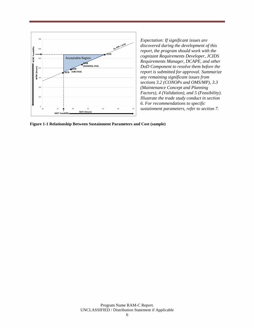
Expectation: If significant issues are
discovered during the development of this
report, the program should work with the
cognizant Requirements Developer, JCIDS
Requirements Manager, DCAPE, and other
DoD Component to resolve them before the
report is submitted for approval. Summarize
any remaining significant issues from
sections 3.2 (CONOPs and OMS/MP), 3.3
(Maintenance Concept and Planning
Factors), 4 (Validation), and 5 (Feasibility).
Illustrate the trade study conduct in section
6. For recommendations to specific
sustainment parameters, refer to section 7.
Figure 1-1 Relationship Between Sustainment Parameters and Cost (sample)
Program Name RAM-C Report.
UNCLASSIFIED / Distribution Statement if Applicable
7
2. Introduction
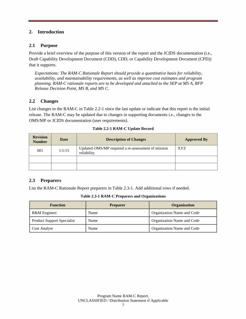
2.1 Purpose
Provide a brief overview of the purpose of this version of the report and the JCIDS documentation (i.e.,
Draft Capability Development Document (CDD), CDD, or Capability Development Document (CPD))
that it supports.
Expectations: The RAM-C Rationale Report should provide a quantitative basis for reliability,
availability, and maintainability requirements, as well as improve cost estimates and program
planning. RAM-C rationale reports are to be developed and attached to the SEP at MS A, RFP
Release Decision Point, MS B, and MS C.
2.2 Changes
List changes to the RAM-C in Table 2.2-1 since the last update or indicate that this report is the initial
release. The RAM-C may be updated due to changes in supporting documents i.e., changes to the
OMS/MP or JCIDS documentation (user requirements).
Table 2.2-1 RAM-C Update Record
Revision
Number Date Description of Changes Approved By
001 1/1/15 Updated OMS/MP required a re-assessment of mission
reliability
XYZ
2.3 Preparers
List the RAM-C Rationale Report preparers in Table 2.3-1. Add additional rows if needed.
Table 2.3-1 RAM-C Preparers and Organizations
Function Preparer Organization
R&M Engineer Name Organization Name and Code
Product Support Specialist Name Organization Name and Code
Cost Analyst Name Organization Name and Code

Program Name RAM-C Report.
UNCLASSIFIED / Distribution Statement if Applicable
8
3. Program Information
Expectation: Section 3 (Program Information) provides the data and information needed to develop
the rationale that program’s sustainment parameters are valid (Section 4) and feasible (Section 5). As
part of the process for developing the report, provide a list of acronyms in Annex A and a list of
references in Annex B.
3.1 System Description
Using the reference design concept from or that will be in the Acquisition Strategy, identify major
subsystems that are subject to R&M requirements. The system description should be user-oriented and
operational and should include all elements of the system, including Government-furnished and
contractor-furnished hardware (whether developmental or not), system software, operating and support
documentation, and the crew and maintainer personnel.
3.2 Sustainment Parameters
In Table 3.2-1, list the sustainment parameters as stated in the JCIDS documentation (Draft CDD, CDD,
or CPD). During the MSA Phase, the data gathering should begin as soon as preliminary inputs are
available from the (user) e.g., from working versions or informal review of the Draft CDD.
Include the source of the sustainment parameters. For example: The sustainment parameters, definitions,
and thresholds with units in Table 3.2-1 were obtained from the Program Name Draft CDD version xx,
dated Month dd, yyyy.
Table 3.2-1 Sustainment Parameters (sample aviation parameters and values based on continuous usage)
Parameter1 Definition (samples) JCIDS
Threshold Units
KPP Materiel
Availability
Measure of the percentage of the total inventory of
a system operationally capable, based on materiel
condition, of performing an assigned mission.
0.65
KPP Operational
Availability
Measure of the percentage of time that a system or
group of systems within a unit are operationally
capable of performing an assigned mission e.g.
uptime/(uptime + downtime).
0.80
KSA Mission
Reliability
46 Hours
KSA Logistics
Reliability
Total number of items removed from the aircraft
that cause a demand to be placed on the supply
system divided by the total number of flight hours.
3.5 Hours
APA Maintenance
Burden
9
APA Corrective
Maintenance2
2.0 Hours
KSA O&S Cost3
$423.7M 2013
Dollars
Program Name RAM-C Report.
UNCLASSIFIED / Distribution Statement if Applicable
9
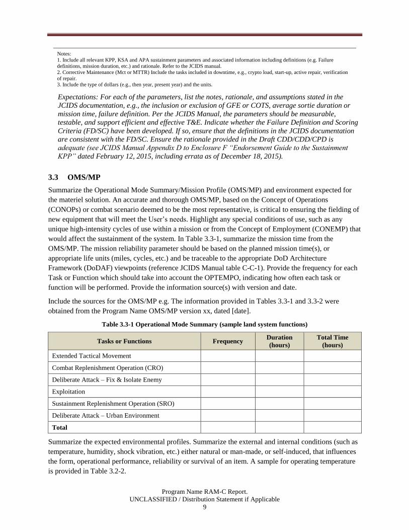
Notes:
1. Include all relevant KPP, KSA and APA sustainment parameters and associated information including definitions (e.g. Failure definitions, mission duration, etc.) and rationale. Refer to the JCIDS manual.
2. Corrective Maintenance (Mct or MTTR) Include the tasks included in downtime, e.g., crypto load, start-up, active repair, verification
of repair. 3. Include the type of dollars (e.g., then year, present year) and the units.
Expectations: For each of the parameters, list the notes, rationale, and assumptions stated in the
JCIDS documentation, e.g., the inclusion or exclusion of GFE or COTS, average sortie duration or
mission time, failure definition. Per the JCIDS Manual, the parameters should be measurable,
testable, and support efficient and effective T&E. Indicate whether the Failure Definition and Scoring
Criteria (FD/SC) have been developed. If so, ensure that the definitions in the JCIDS documentation
are consistent with the FD/SC. Ensure the rationale provided in the Draft CDD/CDD/CPD is
adequate (see JCIDS Manual Appendix D to Enclosure F “Endorsement Guide to the Sustainment
KPP” dated February 12, 2015, including errata as of December 18, 2015).
3.3 OMS/MP
Summarize the Operational Mode Summary/Mission Profile (OMS/MP) and environment expected for
the materiel solution. An accurate and thorough OMS/MP, based on the Concept of Operations
(CONOPs) or combat scenario deemed to be the most representative, is critical to ensuring the fielding of
new equipment that will meet the User’s needs. Highlight any special conditions of use, such as any
unique high-intensity cycles of use within a mission or from the Concept of Employment (CONEMP) that
would affect the sustainment of the system. In Table 3.3-1, summarize the mission time from the
OMS/MP. The mission reliability parameter should be based on the planned mission time(s), or
appropriate life units (miles, cycles, etc.) and be traceable to the appropriate DoD Architecture
Framework (DoDAF) viewpoints (reference JCIDS Manual table C-C-1). Provide the frequency for each
Task or Function which should take into account the OPTEMPO, indicating how often each task or
function will be performed. Provide the information source(s) with version and date.
Include the sources for the OMS/MP e.g. The information provided in Tables 3.3-1 and 3.3-2 were
obtained from the Program Name OMS/MP version xx, dated [date].
Table 3.3-1 Operational Mode Summary (sample land system functions)
Tasks or Functions Frequency Duration
(hours)
Total Time
(hours)
Extended Tactical Movement
Combat Replenishment Operation (CRO)
Deliberate Attack – Fix & Isolate Enemy
Exploitation
Sustainment Replenishment Operation (SRO)
Deliberate Attack – Urban Environment
Total
Summarize the expected environmental profiles. Summarize the external and internal conditions (such as
temperature, humidity, shock vibration, etc.) either natural or man-made, or self-induced, that influences
the form, operational performance, reliability or survival of an item. A sample for operating temperature
is provided in Table 3.2-2.

Program Name RAM-C Report.
UNCLASSIFIED / Distribution Statement if Applicable
10
Table 3.3-2 Summary of Environmental Data (sample land system environment)
Operating Temperature
Climate Operating Climate Temperature % Use
Basic -25°F to 110°F 85%
Hot Up to 130°F 10%
Cold Down to -50°F 3%
Severe Cold Down to -60°F 2%
Expectation: Programs should analyze how the OMS/MP and environmental factors will affect the
system in terms of loads and stresses it encounters and then note the factors from the OMS/MP and
environmental profile that will be used during the validation and feasibility assessment for the
sustainment parameters of the system. Typical factors include operating time, average sortie duration,
duty cycles, and expected environments. The information is used to determine if adjustments are
needed to account for differences in mission and/or operating environment conditions.
3.4 Maintenance Concept and Planning Factors
List the maintenance concept planning factors for the system and source of the values.
Expectations: The planning factors and their values used to determine Mean Down Time (MDT) and
other maintainability KSAs or APAs are needed to validate Ao and AM and should provide a realistic,
definitive, and uniform basis to determine downtime. The planning factors should support the
sustainment capabilities as viewed by the user, maintainer, supplier and transportation providers,
taking into account constraints (e.g., preventative maintenance, reset time, periodic depot
maintenance) and limitations (e.g., “core” requirements, statutory requirements).

Program Name RAM-C Report.
UNCLASSIFIED / Distribution Statement if Applicable
11
4. Validation
Expectations: This section will contain the detailed assessment of the sustainment parameters to
ensure they are valid. The parameters should be consistent with the CONOPS, CONEMP, OMS/MP,
environmental profiles, product support strategy, planned inventory, operating hours (mission
durations) and planned downtimes. In addition, the parameters should support each other, as shown
by calculation and/or M&S and be traceable to the appropriate JCIDS document.
4.1 Operational Availability (AO)
Expectation: Determining the value for Operational Availability requires a comprehensive analysis of
the system and its planned CONOPS, including the planned operating environment, operating tempo,
and reliability and maintenance concepts. The logistics reliability and maintainability KSAs/APAs
used in the AO calculations do not require independent validation. However, they are assessed for
feasibility in Section 5.2.
Provide the equation used to determine Ao. For complex Ao calculations, provide the inputs and outputs
from any simulation models that may have been used to determine Ao. Using the R&M values from
Table 3.2-1 along with other input parameters as needed, calculate the expected Ao.
Placeholder for Ao equation
In Table 4.1-1, provide the JCIDS Ao threshold value, input parameters, and calculated Ao value.
Table 4.1-1 AO Validation (sample aviation values)
JCIDS AO
Threshold
Calculated
AO
Input Parameters2
MFHBF1
Threshold
MDT
MTTR ALDT
0.8 0.8 8.4 0.9 1.2 Note:
1. Use appropriate service definitions for failures that influence AO. In most cases this value of MTBF will
not be the same as the logistics reliability value unless all events that place a demand on the supply system also affect AO.
2. List additional input parameters or assumptions needed for the Ao calculation.
Describe the rationale for the level of reliability stated in the draft CDD/CDD/CPD. Provide the
supporting rationale for the mean down time. Compare the calculated AO value to the threshold value and
verify if the calculated AO is equal to or greater than the JCIDS AO threshold.
4.2 Materiel Availability (AM)
Expectation: Materiel Availability covers the timeframe from placement into operational service
through the planned end of service life. Materiel Availability may be equivalent to Operational
Availability if the total number of a system or group of systems within a unit is the same as the total
inventory, e.g., one command and control center, one fixed land-based radar.
Provide the equation used to determine AM. For complex AM calculations, provide the inputs and outputs
from any simulation models that may have been used to determine AM.
Program Name RAM-C Report.
UNCLASSIFIED / Distribution Statement if Applicable
12
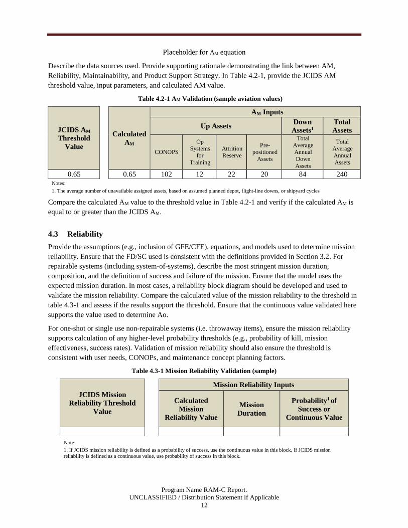
Placeholder for AM equation
Describe the data sources used. Provide supporting rationale demonstrating the link between AM,
Reliability, Maintainability, and Product Support Strategy. In Table 4.2-1, provide the JCIDS AM
threshold value, input parameters, and calculated AM value.
Table 4.2-1 AM Validation (sample aviation values)
JCIDS AM
Threshold
Value
Calculated
AM
AM Inputs
Up Assets Down
Assets1
Total
Assets
CONOPS
Op
Systems
for
Training
Attrition
Reserve
Pre-
positioned
Assets
Total
Average
Annual
Down
Assets
Total
Average
Annual
Assets
0.65 0.65 102 12 22 20 84 240
Notes:
1. The average number of unavailable assigned assets, based on assumed planned depot, flight-line downs, or shipyard cycles
Compare the calculated AM value to the threshold value in Table 4.2-1 and verify if the calculated AM is
equal to or greater than the JCIDS AM.
4.3 Reliability
Provide the assumptions (e.g., inclusion of GFE/CFE), equations, and models used to determine mission
reliability. Ensure that the FD/SC used is consistent with the definitions provided in Section 3.2. For
repairable systems (including system-of-systems), describe the most stringent mission duration,
composition, and the definition of success and failure of the mission. Ensure that the model uses the
expected mission duration. In most cases, a reliability block diagram should be developed and used to
validate the mission reliability. Compare the calculated value of the mission reliability to the threshold in
table 4.3-1 and assess if the results support the threshold. Ensure that the continuous value validated here
supports the value used to determine Ao.
For one-shot or single use non-repairable systems (i.e. throwaway items), ensure the mission reliability
supports calculation of any higher-level probability thresholds (e.g., probability of kill, mission
effectiveness, success rates). Validation of mission reliability should also ensure the threshold is
consistent with user needs, CONOPs, and maintenance concept planning factors.
Table 4.3-1 Mission Reliability Validation (sample)
JCIDS Mission
Reliability Threshold
Value
Mission Reliability Inputs
Calculated
Mission
Reliability Value
Mission
Duration
Probability1 of
Success or
Continuous Value
Note:
1. If JCIDS mission reliability is defined as a probability of success, use the continuous value in this block. If JCIDS mission reliability is defined as a continuous value, use probability of success in this block.
Program Name RAM-C Report.
UNCLASSIFIED / Distribution Statement if Applicable
13
4.4 Operations and Support (O&S) Cost
List the sustainment KPP-related input parameters (e.g., reliability, repair time per failure, quantity of
systems, operating hours) used in the Program Office baseline O&S cost estimate. Compare the input
parameters to the information provided in section 3.2.
If the input parameters are consistent, obtain the baseline O&S cost estimates. Compare the calculated
O&S cost value to threshold. If the calculated values are consistent, the O&S cost values are validated. If
they are not consistent, determine the cause of the inconsistency, e.g., discrepancies in input parameters.
4.5 Summary
Summarize the results of sections 4.1 – 4.4, noting any parameters where the threshold exceeds the
calculated value. If the calculated value (AO, AM, or O&S cost) does not support the threshold, determine
the appropriate input parameters that would be needed and coordinate the information with the
Requirements Developer (Manager) and/or user representative.
Program Name RAM-C Report.
UNCLASSIFIED / Distribution Statement if Applicable
14
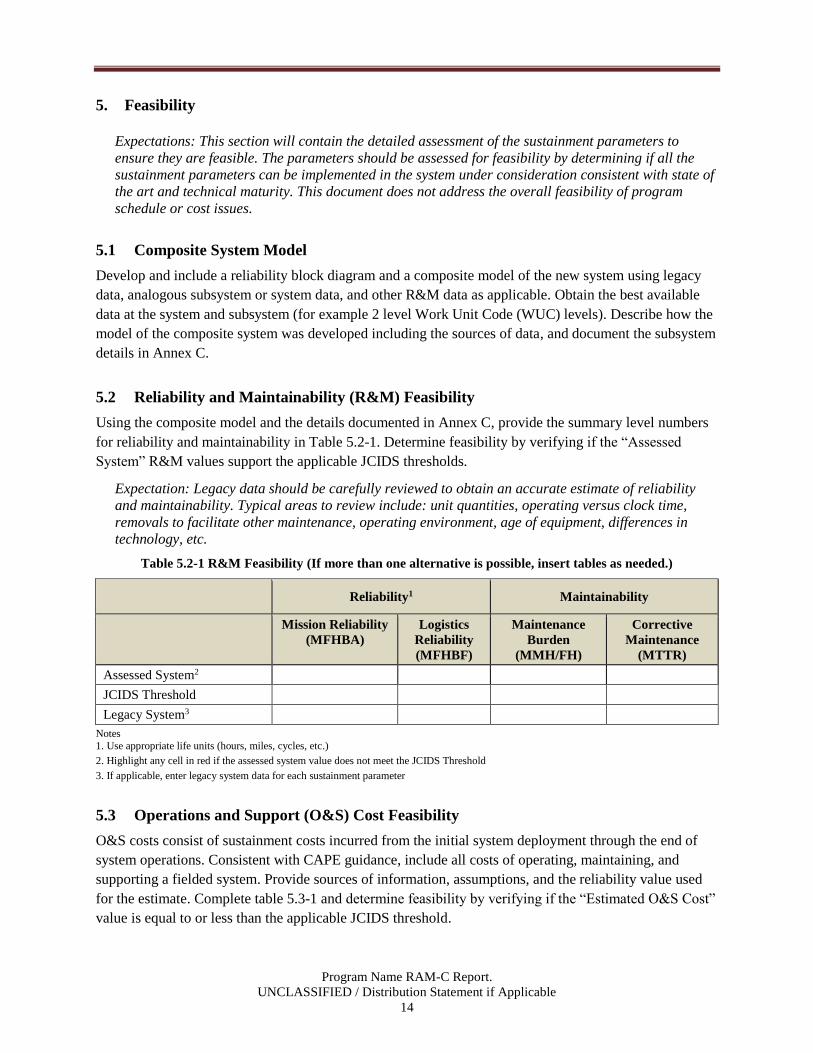
5. Feasibility
Expectations: This section will contain the detailed assessment of the sustainment parameters to
ensure they are feasible. The parameters should be assessed for feasibility by determining if all the
sustainment parameters can be implemented in the system under consideration consistent with state of
the art and technical maturity. This document does not address the overall feasibility of program
schedule or cost issues.
5.1 Composite System Model
Develop and include a reliability block diagram and a composite model of the new system using legacy
data, analogous subsystem or system data, and other R&M data as applicable. Obtain the best available
data at the system and subsystem (for example 2 level Work Unit Code (WUC) levels). Describe how the
model of the composite system was developed including the sources of data, and document the subsystem
details in Annex C.
5.2 Reliability and Maintainability (R&M) Feasibility
Using the composite model and the details documented in Annex C, provide the summary level numbers
for reliability and maintainability in Table 5.2-1. Determine feasibility by verifying if the “Assessed
System” R&M values support the applicable JCIDS thresholds.
Expectation: Legacy data should be carefully reviewed to obtain an accurate estimate of reliability
and maintainability. Typical areas to review include: unit quantities, operating versus clock time,
removals to facilitate other maintenance, operating environment, age of equipment, differences in
technology, etc.
Table 5.2-1 R&M Feasibility (If more than one alternative is possible, insert tables as needed.)
Reliability1 Maintainability
Mission Reliability
(MFHBA)
Logistics
Reliability
(MFHBF)
Maintenance
Burden
(MMH/FH)
Corrective
Maintenance
(MTTR)
Assessed System2
JCIDS Threshold
Legacy System3
Notes
1. Use appropriate life units (hours, miles, cycles, etc.)
2. Highlight any cell in red if the assessed system value does not meet the JCIDS Threshold
3. If applicable, enter legacy system data for each sustainment parameter
5.3 Operations and Support (O&S) Cost Feasibility
O&S costs consist of sustainment costs incurred from the initial system deployment through the end of
system operations. Consistent with CAPE guidance, include all costs of operating, maintaining, and
supporting a fielded system. Provide sources of information, assumptions, and the reliability value used
for the estimate. Complete table 5.3-1 and determine feasibility by verifying if the “Estimated O&S Cost”
value is equal to or less than the applicable JCIDS threshold.

Program Name RAM-C Report.
UNCLASSIFIED / Distribution Statement if Applicable
15
Expectation: O&S costs analysis should be based on the most recent version of the Cost Assessment
and Program Evaluation (CAPE) Operating and Support Cost Estimating Guide. If available for
comparison, the O&S Cost KSA data should be consistent with the capability solution’s life cycle cost
estimate (LCCE), Cost Analysis Requirements Data (CARD) and/or the CAPE independent cost
estimate (ICE).
Table 5.3-1 O&S Cost Feasibility (sample aviation values)
(If more than one alternative is possible, insert columns as needed.)
Cost Element
JCIDS O&S Cost1
Threshold Value
Alternative 1
Estimated2 O&S
Cost Value
Legacy O&S Cost
Value
1.0 Unit Level Manpower 139.4 155.5
2.0 Unit Operations 102.1 143.0
3.0 Maintenance 30.2 59.6
3.1 Consumable Materials and
Repair Parts 3.3 6.5
3.2 Depot Level Repairables 10.4 20.5
3.3 Intermediate Maintenance
(External to Unit-Level) 5.2 10.3
3.4 Depot Maintenance 8.2 16.2
3.5 Other Maintenance 3.0 6.2
4.0 Sustaining Support 98.1 107.7
5.0 Continuing System
Improvements 32.6 56.3
6.0 Indirect Support 38.9 50.8
Total3 423.7 (BY 2013$) 471.4 (BY 2013$) 632.6 (BY 2013$)
Notes
1. Highlight any cell in red if the assessed system value does not meet the JCIDS Threshold
2. Include the type of dollars and the units
5.4 Operational Availability (AO) and Materiel Availability (AM) Feasibility
Using the results of the R&M feasibility assessment in Section 5.2, along with other input parameters as
needed, calculate the feasibility estimate for AO. Using modeling and simulation, perform a feasibility
assessment for AM. For this assessment, data are only required at the system or system-of-systems level
instead of the subsystem level. Complete Table 5.4-1 and assess if AO and AM are feasible. Provide the
outputs of any simulation models used.
Expectation: The analysis should show that AM is feasible based on the expected downtime (scheduled
and unscheduled) for the primary system, primary training asset(s), and the planned calendar time
that any backup assets will be in periodic depot maintenance.
Table 5.4-1 AO and AM Feasibility (sample)
JCIDS Threshold Value
Estimated Value1 Legacy Value
AO
AM
Note
1. Highlight any cell in red if the estimate value does not meet the JCIDS Threshold
Program Name RAM-C Report.
UNCLASSIFIED / Distribution Statement if Applicable
16
5.5 Feasibility Summary
Summarize the results of the RAM-C feasibility assessment process. Identify any issues with specific
sustainment parameters. If the parameters (AO, AM, R, M, or O&S cost) are not feasible, conduct a trade
study (see Section 6) to determine potential parameters that can satisfy the AO and O&S cost thresholds.
Coordinate the information with the Requirements Developer (Manager) and/or user representative.
Expectation: Coordinate with the Requirements Developer and other affected stakeholders prior to
formal submittal of this report if analysis shows that some values are not feasible.

Program Name RAM-C Report.
UNCLASSIFIED / Distribution Statement if Applicable
17
6. Trade Studies
A RAM-C analysis includes a trade study that documents the sensitivity analysis that shows the range of
R&M parameters (e.g., MTBF and MDT) that will satisfy the AO threshold, using the constituent
elements and assumptions of the Ao equation provided in Section 4.1. Provide the results of the
sensitivity analysis (see Figure 6-1) illustrating the trade space for reliability and maintainability along
with the associated O&S costs. Note: costs shown in Figure 6-1 refer to the O&S costs for the associated
reliability values, not the O&S cost for all maintenance events.
Expectation: The RAM-C report will document the supporting rationale for the JCIDS sustainment
parameters. The focus of the trade studies in the RAM-C report will be the sensitivity analysis made
between the sustainment parameters (reliability, availability, maintainability, and O&S cost).
Figure 6-1 Relationship Between Sustainment Parameters and Cost (sample)
Program Name RAM-C Report.
UNCLASSIFIED / Distribution Statement if Applicable
18
7. Summary
Summarize the results of the RAM-C process. Identify any significant degraders to availability and
mission success and the top drivers O&S costs along with any actions in process to mitigate these.
Identify any issues with specific sustainment parameters and the recommendations and feedback that have
been provided to the requirements developers.
Expectation: At the completion of the RAM-C process, all the thresholds should have been validated
and aligned to support Ao, AM, O&S costs, and mission success requirements. The thresholds should
be feasible and consistent with the state of the art and technical maturity. The sustainment parameters
should be balanced to support Ao and O&S costs.

Program Name RAM-C Report.
UNCLASSIFIED / Distribution Statement if Applicable
19
Appendix A – Acronyms
Provide a list of the acronyms used in the report.
ACAT Acquisition Category
ALDT Administrative and Logistics Delay Time
AO Operational Availability
AoA Analysis of Alternatives
AM Materiel Availability
APA Additional Performance Attribute
BIT Built In Test
CAPE Cost Assessment and Program Evaluation
CDD Capability Development Document
CONEMP Concept of Employment
CONOPS Concept of Operations
CPD Capability Production Document
CRO Combat Replenishment Operation
FD/SC Failure Definition/Scoring Criteria
ICD Initial Capability Document
JCIDS Joint Capability Integration Development System
KPP Key Performance Parameter
KSA Key Supporting Attribute
LCSP Life Cycle Support Plan
MCT Mean Corrective Time
MDT Mean Down Time
MLDT Mean Logistics Delay Time
MS Milestone
MFHBF Mean Flight Hours Between Failure
MFHBOMF Mean Flight Hour Between Operational Mission Failure
MMH/FH Maintenance Man Hours per Flight Hour
MTBF Mean Time Between Failure
MTTR Mean Time To Repair
O&S Operating and Support
OMS/MP Operational Mode Summary/Mission Profile
OSD Office of the Secretary of Defense
R&M Reliability and Maintainability
RAM-C Reliability, Availability, Maintainability, and Cost
RFP Request For Proposal
SEP Systems Engineering Plan
SRO Sustainment Replenishment Operation
TAT Turn Around Time
TMRR Technology Maturation and Risk Reduction
WUC Work Unit Code
Program Name RAM-C Report.
UNCLASSIFIED / Distribution Statement if Applicable
20
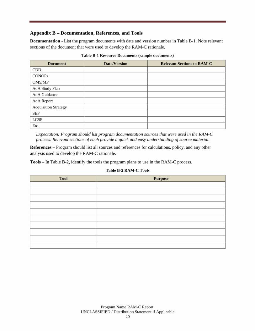
Appendix B – Documentation, References, and Tools
Documentation - List the program documents with date and version number in Table B-1. Note relevant
sections of the document that were used to develop the RAM-C rationale.
Table B-1 Resource Documents (sample documents)
Document Date/Version Relevant Sections to RAM-C
CDD
CONOPs
OMS/MP
AoA Study Plan
AoA Guidance
AoA Report
Acquisition Strategy
SEP
LCSP
Etc.
Expectation: Program should list program documentation sources that were used in the RAM-C
process. Relevant sections of each provide a quick and easy understanding of source material.
References – Program should list all sources and references for calculations, policy, and any other
analysis used to develop the RAM-C rationale.
Tools – In Table B-2, identify the tools the program plans to use in the RAM-C process.
Table B-2 RAM-C Tools
Tool Purpose
Program Name RAM-C Report.
UNCLASSIFIED / Distribution Statement if Applicable
21
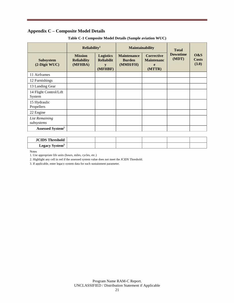
Appendix C – Composite Model Details
Table C-1 Composite Model Details (Sample aviation WUC)
Reliability1 Maintainability
Total
Downtime
(MDT)
O&S
Costs
(3.0) Subsystem
(2-Digit WUC)
Mission
Reliability
(MFHBA)
Logistics
Reliabilit
y
(MFHBF)
Maintenance
Burden
(MMH/FH)
Corrective
Maintenanc
e
(MTTR)
11 Airframes
12 Furnishings
13 Landing Gear
14 Flight Control/Lift
System
15 Hydraulic
Propellers
22 Engine
List Remaining
subsystems
Assessed System2
JCIDS Threshold
Legacy System3
Notes
1. Use appropriate life units (hours, miles, cycles, etc.)
2. Highlight any cell in red if the assessed system value does not meet the JCIDS Threshold.
3. If applicable, enter legacy system data for each sustainment parameter.