Embed Size (px)
Citation preview
Reliability-BasedMechanical Design, Volume 1Component underStatic Load
Xiaobin Le
Synthesis Lectures onMechanical Engineering
XIA
OB
IN LE
RE
LIAB
ILITY-B
ASE
D M
EC
HA
NIC
AL D
ESIG
N, VO
L. 1M
OR
GA
N &
CLA
YPOO
L
Synthesis Lectures onMechanical Engineering
Reliability-Based Mechanical Design, Volume 1Component under Static Load
Xiaobin Le, Wentworth Institute of Technology
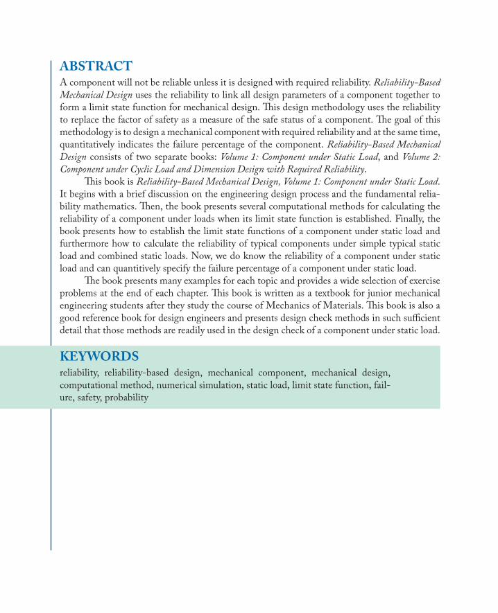
A component will not be reliable unless it is designed with required reliability. Reliability-Based Mechanical Design uses the reliability to link all design parameters of a component together to form a limit state function for mechanical design. This design methodology uses the reliability to replace the factor of safety as a measure of the safe status of a component. The goal of this methodology is to design a mechanical component with required reliability and at the same time, quantitatively indicates the failure percentage of the component. Reliability-Based Mechanical Design consists of two separate books: Volume 1: Component under Static Load, and Volume 2: Component under Cyclic Load and Dimension Design with Required Reliability. This book begins with a brief discussion on the engineering design process and the fundamental reliability mathematics. Then, the book presents several computational methods for calculating the reliability of a component under loads when its limit state function is established. Finally, the book presents how to establish the limit state functions of a component under static load and furthermore how to calculate the reliability of typical components under simple typical static load and combined static loads. Now, we do know the reliability of a component under static load and can quantitively specify the failure percentage of a component under static load. The book presents many examples for each topic and provides a wide selection of exercise problems at the end of each chapter. This book is written as a textbook for junior mechanical engineering students after they study the course of Mechanics of Materials. This book is also a good reference book for design engineers and presents design check methods in such sufficient detail that those methods are readily used in the design check of a component under static load.
ABOUT SYNTHESISThis volume is a printed version of a work that appears in the Synthesis Digital Library of Engineering and Computer Science. Synthesis lectures provide concise original presentations of important research and development topics, published quickly in digital and print formats. For more information, visit our website: http://store.morganclaypool.com
store.morganclaypool.com
Series ISSN: 2573-3168
Reliability-BasedMechanical DesignVolume 1Component under Static Load
Synthesis Lectures onMechanical Engineering
Synthesis Lectures on Mechanical Engineering series publishes 60–150 page publicationspertaining to this diverse discipline of mechanical engineering. The series presents Lectureswritten for an audience of researchers, industry engineers, undergraduate and graduatestudents.Additional Synthesis series will be developed covering key areas within mechanicalengineering.
Reliability-Based Mechanical Design, Volume 1: Component under Static LoadXiaobin Le2019
Solving Practical Engineering Mechanics Problems: Advanced KineticsSayavur I. Bakhtiyarov2019
Natural Corrosion InhibitorsShima Ghanavati Nasab, Mehdi Javaheran Yazd, Abolfazl Semnani, Homa Kahkesh, NavidRabiee, Mohammad Rabiee, Mojtaba Bagherzadeh2019
Fractional Calculus with its Applications in Engineering and TechnologyYi Yang and Haiyan Henry Zhang2019
Essential Engineering Thermodynamics: A Student’s GuideYumin Zhang2018
Engineering DynamicsCho W.S. To2018
Solving Practical Engineering Problems in Engineering Mechanics: DynamicsSayavur I. Bakhtiyarov2018
iiiSolving Practical Engineering Mechanics Problems: KinematicsSayavur I. Bakhtiyarov2018
C Programming and Numerical Analysis: An IntroductionSeiichi Nomura2018
Mathematical MagnetohydrodynamicsNikolas Xiros2018
Design Engineering JourneyRamana M. Pidaparti2018
Introduction to Kinematics and Dynamics of MachineryCho W. S. To2017
Microcontroller Education: Do it Yourself, Reinvent the Wheel, Code to LearnDimosthenis E. Bolanakis2017
Solving Practical Engineering Mechanics Problems: StaticsSayavur I. Bakhtiyarov2017
Unmanned Aircraft Design: A Review of FundamentalsMohammad Sadraey2017
Introduction to Refrigeration and Air Conditioning Systems: Theory and ApplicationsAllan Kirkpatrick2017
Resistance Spot Welding: Fundamentals and Applications for the Automotive IndustryMenachem Kimchi and David H. Phillips2017
MEMS Barometers Toward Vertical Position Detecton: Background Theory, SystemPrototyping, and Measurement AnalysisDimosthenis E. Bolanakis2017
Engineering Finite Element AnalysisRamana M. Pidaparti2017
Copyright © 2020 by Morgan & Claypool
All rights reserved. No part of this publication may be reproduced, stored in a retrieval system, or transmitted inany form or by anymeans—electronic, mechanical, photocopy, recording, or any other except for brief quotationsin printed reviews, without the prior permission of the publisher.
Reliability-Based Mechanical Design, Volume 1: Component under Static Load
Xiaobin Le
www.morganclaypool.com
ISBN: 9781681736594 paperbackISBN: 9781681736600 ebookISBN: 9781681736617 hardcover
DOI 10.2200/S00949ED1V01Y201908MEC020
A Publication in the Morgan & Claypool Publishers seriesSYNTHESIS LECTURES ONMECHANICAL ENGINEERING
Lecture #20Series ISSNPrint 2573-3168 Electronic 2573-3176
Reliability-BasedMechanical DesignVolume 1Component under Static Load
Xiaobin LeWentworth Institute of Technology
SYNTHESIS LECTURES ONMECHANICAL ENGINEERING #20
CM&
cLaypoolMorgan publishers&
ABSTRACTA component will not be reliable unless it is designed with required reliability. Reliability-BasedMechanical Design uses the reliability to link all design parameters of a component together toform a limit state function for mechanical design. This design methodology uses the reliabilityto replace the factor of safety as a measure of the safe status of a component. The goal of thismethodology is to design amechanical component with required reliability and at the same time,quantitatively indicates the failure percentage of the component. Reliability-Based MechanicalDesign consists of two separate books: Volume 1: Component under Static Load, and Volume 2:Component under Cyclic Load and Dimension Design with Required Reliability.
This book is Reliability-Based Mechanical Design, Volume 1: Component under Static Load.It begins with a brief discussion on the engineering design process and the fundamental relia-bility mathematics. Then, the book presents several computational methods for calculating thereliability of a component under loads when its limit state function is established. Finally, thebook presents how to establish the limit state functions of a component under static load andfurthermore how to calculate the reliability of typical components under simple typical staticload and combined static loads. Now, we do know the reliability of a component under staticload and can quantitively specify the failure percentage of a component under static load.
The book presents many examples for each topic and provides a wide selection of exerciseproblems at the end of each chapter. This book is written as a textbook for junior mechanicalengineering students after they study the course of Mechanics of Materials. This book is also agood reference book for design engineers and presents design check methods in such sufficientdetail that those methods are readily used in the design check of a component under static load.
KEYWORDSreliability, reliability-based design, mechanical component, mechanical design,computational method, numerical simulation, static load, limit state function, fail-ure, safety, probability

vii
To my lovely wife, Suyan Zou,and to my wonderful sons, Zelong and Linglong

ix
ContentsPreface . . . . . . . . . . . . . . . . . . . . . . . . . . . . . . . . . . . . . . . . . . . . . . . . . . . . . . . . . . xiii
1 Introduction to Reliability inMechanical Design . . . . . . . . . . . . . . . . . . . . . . . . . 11.1 Engineering Design Process . . . . . . . . . . . . . . . . . . . . . . . . . . . . . . . . . . . . . . . . 1
1.1.1 Phase One: Needs Assessment . . . . . . . . . . . . . . . . . . . . . . . . . . . . . . . . 21.1.2 Phase Two: Design Specifications . . . . . . . . . . . . . . . . . . . . . . . . . . . . . 31.1.3 Phase Three: Conceptual Design . . . . . . . . . . . . . . . . . . . . . . . . . . . . . . 31.1.4 Phase Four: Detailed Design . . . . . . . . . . . . . . . . . . . . . . . . . . . . . . . . . 41.1.5 Phase Five: Implementation . . . . . . . . . . . . . . . . . . . . . . . . . . . . . . . . . . 5
1.2 Failures in Engineering Design . . . . . . . . . . . . . . . . . . . . . . . . . . . . . . . . . . . . . . 61.3 Uncertainty in Engineering . . . . . . . . . . . . . . . . . . . . . . . . . . . . . . . . . . . . . . . . 91.4 Definition of Reliability . . . . . . . . . . . . . . . . . . . . . . . . . . . . . . . . . . . . . . . . . . . 101.5 Importance of Reliability . . . . . . . . . . . . . . . . . . . . . . . . . . . . . . . . . . . . . . . . . . 121.6 Reliability History . . . . . . . . . . . . . . . . . . . . . . . . . . . . . . . . . . . . . . . . . . . . . . . 131.7 Reliability vs. Factor of Safety . . . . . . . . . . . . . . . . . . . . . . . . . . . . . . . . . . . . . . 151.8 Summary . . . . . . . . . . . . . . . . . . . . . . . . . . . . . . . . . . . . . . . . . . . . . . . . . . . . . . 191.9 References . . . . . . . . . . . . . . . . . . . . . . . . . . . . . . . . . . . . . . . . . . . . . . . . . . . . . . 191.10 Exercises . . . . . . . . . . . . . . . . . . . . . . . . . . . . . . . . . . . . . . . . . . . . . . . . . . . . . . . 20
2 Fundamental ReliabilityMathematics . . . . . . . . . . . . . . . . . . . . . . . . . . . . . . . . . 232.1 Introduction . . . . . . . . . . . . . . . . . . . . . . . . . . . . . . . . . . . . . . . . . . . . . . . . . . . . 232.2 Experiment, Outcome, Sample Space, and Event . . . . . . . . . . . . . . . . . . . . . . 232.3 Set Theory . . . . . . . . . . . . . . . . . . . . . . . . . . . . . . . . . . . . . . . . . . . . . . . . . . . . . . 242.4 Definition of Probability . . . . . . . . . . . . . . . . . . . . . . . . . . . . . . . . . . . . . . . . . . 28
2.4.1 Relative Frequency . . . . . . . . . . . . . . . . . . . . . . . . . . . . . . . . . . . . . . . . 282.4.2 Axiomatic Definition . . . . . . . . . . . . . . . . . . . . . . . . . . . . . . . . . . . . . . 30
2.5 Some Basic Operations of Probability . . . . . . . . . . . . . . . . . . . . . . . . . . . . . . . . 322.5.1 Probability of Mutually Exclusive Events . . . . . . . . . . . . . . . . . . . . . . 322.5.2 Probability of an Event in a Finite Sample Space � . . . . . . . . . . . . . . 332.5.3 Probability of Union and Intersection of Two Events . . . . . . . . . . . . . 342.5.4 Probability of a Complementary Event . . . . . . . . . . . . . . . . . . . . . . . . 35
x2.5.5 Probability of Statistically Independent Events . . . . . . . . . . . . . . . . . 362.5.6 Conditional Probability . . . . . . . . . . . . . . . . . . . . . . . . . . . . . . . . . . . . 372.5.7 Total Probability Theorem . . . . . . . . . . . . . . . . . . . . . . . . . . . . . . . . . . 392.5.8 Bayes’ Rule . . . . . . . . . . . . . . . . . . . . . . . . . . . . . . . . . . . . . . . . . . . . . . 41
2.6 Random Variable . . . . . . . . . . . . . . . . . . . . . . . . . . . . . . . . . . . . . . . . . . . . . . . . 422.7 Mean, Standard Deviation, and Coefficient of Variance . . . . . . . . . . . . . . . . . 432.8 Histogram . . . . . . . . . . . . . . . . . . . . . . . . . . . . . . . . . . . . . . . . . . . . . . . . . . . . . . 46
2.8.1 Definition of a Histogram . . . . . . . . . . . . . . . . . . . . . . . . . . . . . . . . . . 462.8.2 Histogram by Excel and MATLAB . . . . . . . . . . . . . . . . . . . . . . . . . . . 49
2.9 Probability Functions . . . . . . . . . . . . . . . . . . . . . . . . . . . . . . . . . . . . . . . . . . . . . 512.9.1 Probability Functions of a Continuous Random Variable . . . . . . . . . . 512.9.2 Probability Functions of a Discrete Random Variable . . . . . . . . . . . . . 55
2.10 Mean of a Random Variable . . . . . . . . . . . . . . . . . . . . . . . . . . . . . . . . . . . . . . . 572.11 Standard Deviation and Coefficient of Variance . . . . . . . . . . . . . . . . . . . . . . . . 602.12 Some Typical Probability Distributions . . . . . . . . . . . . . . . . . . . . . . . . . . . . . . 63
2.12.1 Binomial Distribution . . . . . . . . . . . . . . . . . . . . . . . . . . . . . . . . . . . . . . 632.12.2 Poisson Distribution . . . . . . . . . . . . . . . . . . . . . . . . . . . . . . . . . . . . . . . 672.12.3 Uniform Distribution . . . . . . . . . . . . . . . . . . . . . . . . . . . . . . . . . . . . . . 692.12.4 Normal Distribution . . . . . . . . . . . . . . . . . . . . . . . . . . . . . . . . . . . . . . . 712.12.5 Log-Normal Distribution . . . . . . . . . . . . . . . . . . . . . . . . . . . . . . . . . . . 792.12.6 Weibull Distribution . . . . . . . . . . . . . . . . . . . . . . . . . . . . . . . . . . . . . . . 822.12.7 Exponential Distribution . . . . . . . . . . . . . . . . . . . . . . . . . . . . . . . . . . . 85
2.13 Goodness-of-Fit Test: �2 Test . . . . . . . . . . . . . . . . . . . . . . . . . . . . . . . . . . . . . . 872.13.1 Introduction . . . . . . . . . . . . . . . . . . . . . . . . . . . . . . . . . . . . . . . . . . . . . 872.13.2 The Chi-Square Test . . . . . . . . . . . . . . . . . . . . . . . . . . . . . . . . . . . . . . . 882.13.3 The Chi-Square (�2) Goodness-of-Fit Test by the Matlab Program . 94
2.14 References . . . . . . . . . . . . . . . . . . . . . . . . . . . . . . . . . . . . . . . . . . . . . . . . . . . . . . 972.15 Exercises . . . . . . . . . . . . . . . . . . . . . . . . . . . . . . . . . . . . . . . . . . . . . . . . . . . . . . . 98
3 ComputationalMethods for the Reliability of a Component . . . . . . . . . . . . . . 1113.1 Introduction . . . . . . . . . . . . . . . . . . . . . . . . . . . . . . . . . . . . . . . . . . . . . . . . . . . 1113.2 Limit State Function . . . . . . . . . . . . . . . . . . . . . . . . . . . . . . . . . . . . . . . . . . . . 1123.3 Reliability of a Component with Two Random Variables . . . . . . . . . . . . . . . 115
3.3.1 Interference Method . . . . . . . . . . . . . . . . . . . . . . . . . . . . . . . . . . . . . 1153.3.2 Computation of Reliability When Both are Normal Distributions . 1183.3.3 Computation of Reliability When Both are Log-normal
Distributions . . . . . . . . . . . . . . . . . . . . . . . . . . . . . . . . . . . . . . . . . . . . 120
xi3.3.4 Computation of Reliability When Both are Exponential
Distributions . . . . . . . . . . . . . . . . . . . . . . . . . . . . . . . . . . . . . . . . . . . . 1223.4 Reliability Index ˇ . . . . . . . . . . . . . . . . . . . . . . . . . . . . . . . . . . . . . . . . . . . . . . 1233.5 The First-Order Second-Moment (FOSM) Method . . . . . . . . . . . . . . . . . . . 126
3.5.1 The FOSM Method for a Linear Limit State Function . . . . . . . . . . 1273.5.2 The FOSM Method for a Nonlinear State Function . . . . . . . . . . . . . 128
3.6 The Hasofer–Lind (H-L) Method . . . . . . . . . . . . . . . . . . . . . . . . . . . . . . . . . 1333.7 The Rackwitz and Fiessler (R-F) method . . . . . . . . . . . . . . . . . . . . . . . . . . . . 1403.8 The Monte Carlo Method . . . . . . . . . . . . . . . . . . . . . . . . . . . . . . . . . . . . . . . . 1503.9 Summary . . . . . . . . . . . . . . . . . . . . . . . . . . . . . . . . . . . . . . . . . . . . . . . . . . . . . 1563.10 References . . . . . . . . . . . . . . . . . . . . . . . . . . . . . . . . . . . . . . . . . . . . . . . . . . . . . 1573.11 Exercises . . . . . . . . . . . . . . . . . . . . . . . . . . . . . . . . . . . . . . . . . . . . . . . . . . . . . . 157
4 Reliability of a Component under Static Load . . . . . . . . . . . . . . . . . . . . . . . . . 1614.1 Introduction . . . . . . . . . . . . . . . . . . . . . . . . . . . . . . . . . . . . . . . . . . . . . . . . . . . 1614.2 Geometric Dimension as a Random Variable . . . . . . . . . . . . . . . . . . . . . . . . . 1614.3 Static Loading as a Random Variable . . . . . . . . . . . . . . . . . . . . . . . . . . . . . . . 1644.4 Mechanical Properties of Materials as Random Variables . . . . . . . . . . . . . . . 1684.5 Estimation of Some Design Parameters . . . . . . . . . . . . . . . . . . . . . . . . . . . . . 1694.6 Reliability of a Rod under Axial Loading . . . . . . . . . . . . . . . . . . . . . . . . . . . . 178
4.6.1 Reliability of a Rod under Axial Loading for a Strength Issue . . . . . 1784.6.2 Reliability of a Rod under Axial Loading for a Deformation Issue . 186
4.7 Reliability of a Component under Direct Shearing . . . . . . . . . . . . . . . . . . . . 1934.8 Reliability of a Shaft under Torsion . . . . . . . . . . . . . . . . . . . . . . . . . . . . . . . . . 198
4.8.1 Reliability of a Shaft under Torsion for a Strength Issue . . . . . . . . . 1984.8.2 Reliability of a Shaft under Torsion for a Deformation Issue . . . . . . 203
4.9 Reliability of a Beam under Bending Moment . . . . . . . . . . . . . . . . . . . . . . . . 2054.9.1 Reliability of a Beam under Bending for a Strength Issue . . . . . . . . . 2054.9.2 Reliability of a Beam under Bending for a Deflection Issue . . . . . . . 212
4.10 Reliability of a Component under Combined Stresses . . . . . . . . . . . . . . . . . . 2154.10.1 Reliability of a Component of Ductile Material under Combined
Stresses . . . . . . . . . . . . . . . . . . . . . . . . . . . . . . . . . . . . . . . . . . . . . . . . 2154.10.2 Reliability of a Component of Brittle Material under Combined
Stresses . . . . . . . . . . . . . . . . . . . . . . . . . . . . . . . . . . . . . . . . . . . . . . . . 2224.11 Summary . . . . . . . . . . . . . . . . . . . . . . . . . . . . . . . . . . . . . . . . . . . . . . . . . . . . . 2284.12 References . . . . . . . . . . . . . . . . . . . . . . . . . . . . . . . . . . . . . . . . . . . . . . . . . . . . . 2324.13 Exercises . . . . . . . . . . . . . . . . . . . . . . . . . . . . . . . . . . . . . . . . . . . . . . . . . . . . . . 232
xii
A Samples ofMATLAB® Programs . . . . . . . . . . . . . . . . . . . . . . . . . . . . . . . . . . . . 241A.1 The H-L Method for Example 3.11 . . . . . . . . . . . . . . . . . . . . . . . . . . . . . . . . 241A.2 The R-F Method for Example 3.13 . . . . . . . . . . . . . . . . . . . . . . . . . . . . . . . . . 243A.3 The Monte Carlo Method for Example 3.14 . . . . . . . . . . . . . . . . . . . . . . . . . 245
Author’s Biography . . . . . . . . . . . . . . . . . . . . . . . . . . . . . . . . . . . . . . . . . . . . . . . . 247
xiii
PrefaceReliability-Based Mechanical Design consists of two separate books: Volume 1: Component underStatic Load, and Volume 2: Component under Cyclic Load and Dimension Design with RequiredReliability.
Volume 1 consists of four chapters and Appendix A. They are:
• Chapter 1: Introduction to Reliability in Mechanical Design;
• Chapter 2: Fundamental Reliability Mathematics;
• Chapter 3: Computational Methods for the Reliability of a Component;
• Chapter 4: Reliability of a Component under Static Load, and,
• Appendix A: Samples of MATLAB Programs.
Volume 2 consists of three chapters and two appendixes. They are:
• Chapter 1: Introduction and Cyclic Loading Spectrum;
• Chapter 2: Reliability of a Component under Cyclic Load;
• Chapter 3: The Dimension of a Component with Required Reliability;
• Appendix A: Three Computational Methods for the Reliability of a Component; and,
• Appendix B: Samples of MATLAB Programs.
The first book discusses fundamental concepts for implementing reliability in mechanicaldesign and the reliability of a component under static load. The second book presents moreadvanced topics, including the reliability of a component under cyclic load and the dimensiondesign with required reliability.
Why does a component fail even the factor of safety of a component is more than therequired factor of safety, for example, 2.5? If a component will fail, what is its possible percent-age of the failure? This book presents how to determine the reliability, and quantitively predictthe percentage of the failures of a component under static load. Therefore, we can provide thereliability and also indicate a possible percentage of failure of a component under static load.
This book is written as a textbook and is based on a series of lecture notes of an electivecourse for junior mechanical students. Every topic is discussed in sufficient detail and demon-strated by many examples so students or design engineers can readily use them in mechanical
xiv PREFACEdesign check. At the end of each chapter, there is a wide selection of exercises. This book canalso be used as a reference book for design engineers.
This book consists of four chapters and Appendix A. A concise summary of each chapterare as follows.
• Chapter 1: Introduction to Reliability in Mechanical DesignThis chapter serves as an introduction and will discuss the engineering design process,failures, and uncertainty in engineering design, reliability definition, and history.
• Chapter 2: Fundamental Reliability MathematicsThis chapter discusses the fundamental concepts and definitions of probabilistic theoryfor the preparation of their implementation for mechanical design. This chapter enablesa person without any knowledge of probability theory to use this book to conduct thereliability-based mechanical design.
• Chapter 3: Computational Methods of the Reliability of a ComponentThis chapter discusses several computational methods of the reliability of a componentwhen the limit state function of a component under load is established. Those methodsinclude the interference method, the First-Order Second-Moment (FOSM) method, theHasoder-Lind (H-L)method, the Rachwitz-Fiessler (R-F)method, and theMonte Carlomethod.
• Chapter 4: Reliability of a Component under Static LoadThis chapter presents typical limit state functions of a component under each typical staticload and combined load, and further demonstrate how to calculate the reliability of compo-nents under any type of static loads. Five typical component cases presented in this chapterinclude a bar under axial static load, a pin under direct shear static load, a shaft under statictorsion, a beam under static bending moment, and a component under combined staticloads.
• Appendix A: Samples of three MATLAB ProgramsAppendix A provides three MATLAB programs as references for calculating the reliabilityof a component under static load. These three samples of MATLAB programs include onefor the Hasoder-Lind (H-L) method, one for the Rachwitz-Fiessler (R-F) method, andone for the Monte Carlo method.
This book could not have been completed and published without lots of encouragementand help. First, I sincerely thank Mechanical Department Chairman and Professor MickaelJackson at the Wentworth Institute of Technology, whose encouragement motivated me to opentwo technical elective courses about the reliability in mechanical engineering. Second, I sincerelythank Professors Anthony William Duva and Richard L. Roberts for reviewing some of the
PREFACE xvmanuscripts. Third, I sincerely thank Morgan & Claypool Publishers and Executive Editor PaulPetralia for helping with this publication. Finally, I sincerely thank my lovely wife, Suyan Zou.Without her support, I could not have completed this book.
Xiaobin LeOctober 2019

1
C H A P T E R 1
Introduction to Reliability inMechanical Design
1.1 ENGINEERINGDESIGNPROCESSMechanical engineering is one of the oldest branches of science. Mechanical design is one ofthe primary purposes of mechanical engineering. It has created a lot of fantastic design projectswhich greatly benefit human society such as the steam engine, elevator, bridge crane, automobile,train, ship, and airplane. Unfortunately, some failures of mechanical design projects also causeddisasters to human society such as the Space Shuttle Challenger Disaster on January 28, 1986,which was mainly due to the failure in mechanical component design and resulted in the deathof all seven crew members including five NASA astronauts and two payload specialists. Becauseof the complexity of modern mechanical design, mechanical design theory has been constantlydeveloped and updated. This book contributes to mechanical design theory by presenting howto conduct reliability-based mechanical design.
The first key topic of mechanical design theory is the description of the engineering de-sign or engineering design process, which is a summary of past success and failure of designexperience. This section will briefly describe the definition of engineering design and conciselyexplain the engineering design process.
There are many definitions of engineering design. The Accreditation Board for Engineer-ing and Technology (ABET) definition of engineering design is: “Engineering design is the processof devising a system, component, or process to meet desired needs. It is a decision-making process (ofteniterative), in which the basic science and mathematics and engineering sciences are applied to convertresources optimally to meet a stated objective. Among the fundamental elements of the design process arethe establishment of objectives and criteria, synthesis, analysis, construction, testing, and evaluation.”This definition explains the four key aspects of the engineering design.
• Engineering design is a process.
• Engineering design utilizes many different skills with an iterative, decision-making, andsystematic approach.
• Engineering design will build an object, including a system, component, or process undersome constraints.
• The purpose of the engineering design is to meet the project’s required needs.
2 1. INTRODUCTIONTORELIABILITY INMECHANICALDESIGNThe most important aspect of engineering design is that engineering design is a process.
Why is it a process? Engineering design is a process not because it consists of several steps andmight take a long time to complete it, but mainly because the final approval of the design isnot by theoretical calculations or numerical simulations, but by the actual testing on the pro-totype. For example, when we do a complicated math problem, which might need a few hoursor a few days, we know the obtained solution is right or not after we finish it because we canplug them in the equations to check the solution. For an engineering design project, even theaccurate theoretical calculation and complicated numerical simulation results suggest that thedesign should be safe and could satisfy the design requirements, the design product cannot bereleased to mass-production and customers. Engineering design experience has approved thatdesign product without throughout testing on the prototypes might cause significant problemsfor customers and company.
According to the last few hundred years of engineering successful and unsuccessful experi-ence, lots of different theory about the design process have been proposed for guiding engineersto conduct the engineering design. The five-phase engineering design process proposed by Ger-ard Voland is one of these good theories. The five-phase engineering design process includes:(1) PhaseOne: Needs Assessment; (2) Phase Two:Design Specifications; (3) PhaseThree: Con-ceptual Designs; (4) Phase Four: Detailed Design; and (5) Phase Five: Implementation. Thedetailed information about the five-phase design theory can be found in the book Engineeringby Design, authored by Gerard Voland [1]. We will provide brief descriptions of the five-phaseengineering design process as follows [2].
1.1.1 PHASEONE: NEEDSASSESSMENTThe main task in Phase One is to check whether needs are real and feasible or not. The “needs”is a current problem or current unsatisfactory status. The needs can come from personal expe-rience, customers, or society. However, some claiming demands might not be a real need andmight fade quickly. Some needs might not be feasible for the project team because it might notbe technically feasible or financially viable. For example, many people wish that they could havea device which could directly import the knowledge of books into their brains. This device mightbe feasible in the future. However, it is certainly not technically feasible now. For another ex-ample, constructing a more advanced airplane is always a real need, but it will not be financiallyviable for a small company because it has limited human resources and funding.
The outcomes of Phase One are as follows. (1) The need is not a real need. No furtheraction is needed. (2) The need is a real need, but it is not technically nor financially feasiblefor the project team. The need might be stored for future use. No immediate action is needed.(3) The need is a real and feasible need for the project team. Only if the need assessment passesPhase One, will it proceed to Phase Two: Design Specifications. However, the design projector the project team is not still officially established or formed.
1.1. ENGINEERINGDESIGNPROCESS 3
1.1.2 PHASETWO:DESIGN SPECIFICATIONSThe main tasks in Phase Two are: (1) true understanding of the needs; (2) search existing relatedsolutions for the needs; and (3) determine design specifications for the needs. The needs in PhaseOne, which might come from the sale department, or customers, or society, are generally de-scribed by general language. These needs are required to be rephrased by engineering language.Before this, the first step is to have a true understanding of the needs, and then some primarycriteria are set up. Before we start to search existing solutions or possible solutions, we mustfully and truly understand the need, or the real meanings of the need, or the real requirementsfrom the customers. For example, if customers require us to design transportation for them. Ifwe provide the transportation which is driven by gasoline or diesel engine or electrical engine,we make a big mistake when the power source in that region for the customers is natural gas.The second step is to search existing or possible solutions for the need by using the primary cri-teria established in the first step. Do not reinvent the wheel. So, the design project for the needsshould use up-to-date techniques. After lots of background investigation has been done, andlots of related up-to-date technical information has been collected, the third step is to establishdesign specifications for the needs. There are several common or general design goals that areusually associated with design projects such as safety, environmental protection, public accep-tance, reliability, performance, durability, ease of operation, use of standard parts, minimumcost, minimum maintenance and ease of maintenance, and manufacturability. The design spec-ifications do not mean these common or general goals, which are certainly considered in detail.The design specifications properly established in the third step are: (1) any special statement forthe design project and (2) any numerical value related to the design project. Two examples ofdesign specification are: “The device must work properly in a very moist environment” and “thefactor of safety is 3.5.”
The outcomes of Phase Two are as follows. (1) The needs could be satisfied by an existingproduct, or profitable product could not be constructed due to the highly competing market.So, no further action is required. The design project will not be set up. (2) Proper design speci-fications have been established and will be satisfied by design. The design project will be set up,and the project team will be formally formed.
Only after the design specifications are established will the design project and project teambe formally assembled. Now the design project will move to Phase Three: Conceptual Design.
1.1.3 PHASETHREE: CONCEPTUALDESIGNThe main task in Phase Three is to develop a pool of all possible alternative solutions for thedesign project, and then to generate several best alternative solutions for the design project fromthe pool of all possible alternative solutions.
Modern design projects are typically complicated with several functions or subsystems.The following four steps can be used to conduct the conceptual design.
4 1. INTRODUCTIONTORELIABILITY INMECHANICALDESIGNStep 1: Decompose a design project into several subsystems or subunits according to theirfunctions. Any design project normally consists of several subsystems/subunits or severaldifferent functions. It is very complicated to generate solutions for a unit with severalfunctions. However, it will be relatively easy to generate solutions for a subunit with onlyone function. So, in this step, the design project will be decomposed into a lot of subsys-tems/subunits, which have only one key function or performance.
Step 2: Develop a lot of possible options for each subsystem/subunit. A subsystem/subunitwith single function or performance can be abstracted into a general catalog, which will bebacked up by the whole engineering technique and knowledge. Then, the project team cangenerate many solutions for each subsystem/subunit. In this step, full information researchshould be conducted. The good quality of these solutions will determine the quality of thefinal design solution because the final design solution of the design project will be formedfrom these solutions.
Step 3: Form a pool of alternatives for the design project. The combination of one optionfrom each subsystem/subunit will form one alternative for the design project. This combi-nation will typically be a large quantity of possible alternative designs for the project. Forexample, if there are six subsystems, and each subsystem has three solutions, the possiblealternatives for a design project will be equal to 36 D 729.
Step 4: Use personal experiences, judgment, or group discussion to choose several bestprospective alternatives for the design project. The project team does not have enoughtime and money to build and test each possible alternative. It is also not necessary. So,the project team will use personal experience, judgment, and group discussion to pick upseveral best alternatives for further investigations in the next stage.
The outcome of Phase Three: Conceptual Design offers several best alternatives for thedesign project, from which the final design solution will be selected.
1.1.4 PHASE FOUR:DETAILEDDESIGNThe main tasks in Phase Four are: (1) create a virtual product and run the virtual experimentson the virtual product; (2) choose the final design option for the design project; and (3) test andmodify the prototype and finalize the final design option for the design project.
In modern engineering society, lots of modern advanced tools are available for engineer-ing design. For example, computer-aided design (CAD) software can be used to build a virtualcomponent (VC), virtual assembly (VA), and virtual product (VP). A VC has the same dimen-sions, the same material, and the same behaviors of a real component. So, it looks like the realcomponent and behaves like the real component but is stored in a digital form. A VA is a digitalform of a real assembly. The VP is a digital form of a real product. Lots of engineering simula-tion software such as Solidworks Simulation and ANSYS, which are commercial finite element
1.1. ENGINEERINGDESIGNPROCESS 5analysis software, can be used to test the functions and stress/strain of a virtual component,or assembly, or product under different loading conditions. A lot of different computer-aidedmanufacturing (CAM) can be used to animate the manufacturing process of a VC to check thefeasibility of manufacturing.
The first task in Phase Four is to construct VCs, VAs, and VPs, and then use availablecomputer software to conduct the numerical simulation to check the performances and func-tions of different design options. Only some key components or key sub-assemblies might bemanufactured and experimented on the prototypes of components or sub-assemblies for check-ing the performance of functions. The contents of this book will be an engineering design theoryto determine the dimension of a component with required reliability, that is, VC.
The second main task is to determine the best design option after performance and func-tions of several design options under consideration have been evaluated through virtual tests,that is, numerical simulation on VCs, VAs, and VPs. Since design project has several designspecifications and functions, systematic evaluation methods such as Decision Matrix, which isfully explained in the book Engineering by Design [1], could be implemented to choose the bestoption.
The last main task is to build the prototype of the final design option and then thor-oughly test and modify it until all required design specifications, performance, and functions areproperly satisfied by the final design option.
The outcome of Phase Four is a tested and approved final design option, which is readyto be released for production.
1.1.5 PHASE FIVE: IMPLEMENTATIONThe last phase in the engineering design process is the implementation, which mainly meanstransforming a design into reality. The main task in Phase Five is to prepare a complete setof engineering documentation, such as drawing, part list, operation and maintenance manual,quality control procedures, manufacturing procedures, and manufacturing tool and fixture de-sign. The complete set of engineering documentation is the technical information by which thefinal design option can be manufactured or duplicated. The outcome of Phase Five is a completeset of engineering documentation.
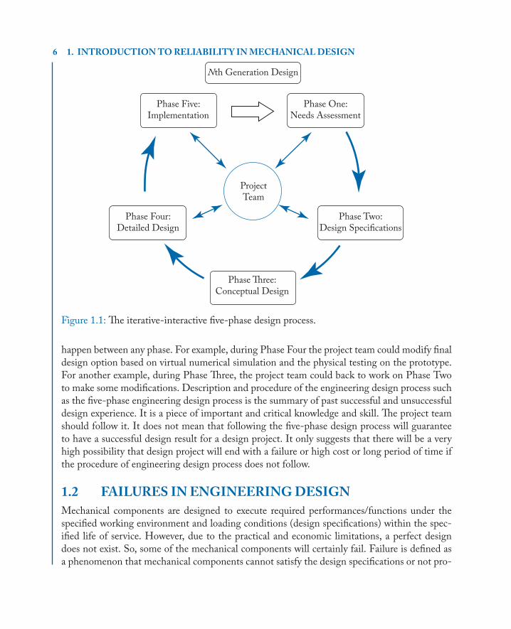
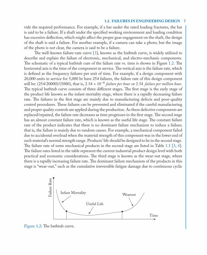
An iterative-interactive five-phase engineering design process shown in Figure 1.1 in-cludes six items. The center is the project team. The project team is the core of any engineeringdesign process. The iterative-interactive process and all other design activities are carried out byand through the project team. The other five elements are needs assessment (Phase One), de-sign specification (Phase Two), conceptual design (Phase Three), detailed design (Phase Four),and implementation (Phase Five). An engineering design project has its own life—it starts atPhase One: Needs Assessment and ends at Phase Five: Implementation. The flow chart of theengineering design process is naturally from Phase One, to Phase Two, to Phase Three, thento Phase Four, and finally to Phase Five. During this design process, interactive activities could
6 1. INTRODUCTIONTORELIABILITY INMECHANICALDESIGN
Nth Generation Design
ProjectTeam
Phase Five:Implementation
Phase Four:Detailed Design
Phase Two:Design Specifications
Phase "ree:Conceptual Design
Phase One:Needs Assessment
Figure 1.1: The iterative-interactive five-phase design process.
happen between any phase. For example, during Phase Four the project team could modify finaldesign option based on virtual numerical simulation and the physical testing on the prototype.For another example, during Phase Three, the project team could back to work on Phase Twoto make some modifications. Description and procedure of the engineering design process suchas the five-phase engineering design process is the summary of past successful and unsuccessfuldesign experience. It is a piece of important and critical knowledge and skill. The project teamshould follow it. It does not mean that following the five-phase design process will guaranteeto have a successful design result for a design project. It only suggests that there will be a veryhigh possibility that design project will end with a failure or high cost or long period of time ifthe procedure of engineering design process does not follow.
1.2 FAILURES INENGINEERINGDESIGNMechanical components are designed to execute required performances/functions under thespecified working environment and loading conditions (design specifications) within the spec-ified life of service. However, due to the practical and economic limitations, a perfect designdoes not exist. So, some of the mechanical components will certainly fail. Failure is defined asa phenomenon that mechanical components cannot satisfy the design specifications or not pro-
1.2. FAILURES INENGINEERINGDESIGN 7vide the required performance. For example, if a bar under the rated loading fractures, the baris said to be a failure. If a shaft under the specified working environment and loading conditionhas excessive deflection, which might affect the proper gear engagement on the shaft, the designof the shaft is said a failure. For another example, if a camera can take a photo, but the imageof the photo is not clear, the camera is said to be a failure.
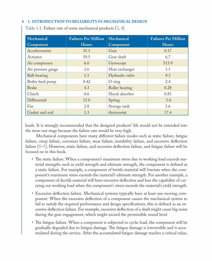
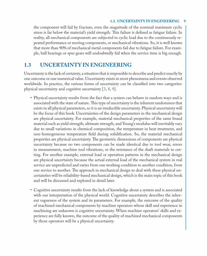
The well-known failure-rate curve [3], known as the bathtub curve, is widely utilized todescribe and explain the failure of electronic, mechanical, and electro-mechanic components.The schematic of a typical bathtub cure of the failure rate vs. time is shown in Figure 1.2. Thehorizontal axis is the time of the component in service. The vertical axis is the failure rate, whichis defined as the frequency failures per unit of time. For example, if a design component with20,000 units in service for 5,000 hr have 254 failures, the failure rate of this design componentwill be: (254/20000)/(5000), that is, 2:54 � 10�6 failure per hour or 2:54 failure per million hour.The typical bathtub curve consists of three different stages. The first stage is the early stage ofthe product life known as the infant mortality stage, where there is a rapidly decreasing failurerate. The failures in the first stage are mainly due to manufacturing defects and poor-qualitycontrol procedures. These failures can be prevented and eliminated if the careful manufacturingand proper quality controls are applied during the production. As these defective components arereplaced/repaired, the failure rate decreases as time progresses in the first stage. The second stagehas an almost constant failure rate, which is known as the useful life stage. The constant failurerate of the product indicates that there is no dominant failure mechanism to induce a failure;that is, the failure is mainly due to random causes. For example, a mechanical component faileddue to accidental overload when the material strength of this component was in the lower end ofsuchmaterial’s normal strength range. Products’ life should be designed to be in the second stage.The failure rate of some mechanical products in the second stage are listed in Table 1.1 [3, 4].The failure rates listed in the table represent the current industrial product design level with bothpractical and economic considerations. The third stage is known as the wear-out stage, wherethere is a rapidly increasing failure rate. The dominant failure mechanism of the products in thisstage is “wear-out,” such as the cumulative irreversible fatigue damage due to continuous cyclic
Infant Mortality Wearout
Time
Fai
lure
Rat
e
Useful Life
Figure 1.2: The bathtub curve.
8 1. INTRODUCTIONTORELIABILITY INMECHANICALDESIGN
Table 1.1: Failure rate of some mechanical products [3, 4]
Mechanical
Component
Failures Per Million
Hours
Mechanical
Component
Failures Per Million
Hours
Accelerometer 35.1 Gear 0.17
Actuator 50.5 Gear shaft 6.7
Air compressor 6.0 Gyroscope 513.9
Air pressure gauge 2.6 Heat exchanger 1.1
Ball-bearing 1.1 Hydraulic valve 9.3
Boiler feed pump 0.42 O-ring 2.4
Brake 4.3 Roller bearing 0.28
Clutch 0.6 Shock absorber 0.81
Diff erential 15.0 Spring 5.0
Fan 2.8 Storage tank 1.6
Gasket and seal 1.3 thermostat 17.4
loads. It is strongly recommended that the designed products’ life would not be extended intothe wear-out stage because the failure rate would be very high.
Mechanical components have many different failure modes such as static failure, fatiguefailure, creep failure, corrosion failure, wear failure, instability failure, and excessive deflectionfailure [5–7]. However, static failure, and excessive deflection failure, and fatigue failure will befocused on in this book.
• The static failure. When a component’s maximum stress due to working load exceeds ma-terial strengths such as yield strength and ultimate strength, the component is defined asa static failure. For example, a component of brittle material will fracture when the com-ponent’s maximum stress exceeds the material’s ultimate strength. For another example, acomponent of ductile material will have excessive deflection and lose the capability of car-rying out working load when the component’s stress exceeds the material’s yield strength.
• Excessive deflection failure. Mechanical systems typically have at least one moving com-ponent. When the excessive deflection of a component causes the mechanical system tofail to satisfy the required performance and design specifications, this is defined as an ex-cessive deflection failure. For example, excessive deflection of a shaft might cause big noiseduring the gear engagement, which might exceed the permissible sound level.
• The fatigue failure. When a component is subjected to cyclic load, the component will begradually degraded due to fatigue damage. The fatigue damage is irreversible and is accu-mulated during the service. After the accumulated fatigue damage reaches a critical value,
1.3. UNCERTAINTY INENGINEERING 9the component will fail by fracture, even the magnitude of the nominal maximum cyclicstress is far below the material’s yield strength. This failure is defined as fatigue failure. Inreality, all mechanical components are subjected to cyclic load due to the continuously re-peated performance or moving components, or mechanical vibrations. So, it is well knownthat more than 90% of mechanical metal components fail due to fatigue failure. For exam-ple, ball bearings or spur gears will undoubtedly fail when the service time is big enough.
1.3 UNCERTAINTY INENGINEERINGUncertainty is the lack of certainty, a situation that is impossible to describe and predict exactly byone outcome or one numerical value. Uncertainty exists in most phenomena and events observedworldwide. In practice, the various forms of uncertainty can be classified into two categories:physical uncertainty and cognitive uncertainty [3, 8, 9].
• Physical uncertainty results from the fact that a system can behave in random ways and isassociated with the state of nature.This type of uncertainty is the inherent randomness thatexists in all physical parameters, so it is an irreducible uncertainty. Physical uncertainty willbe the focus of this book. Uncertainties of the design parameters in the mechanical designare physical uncertainty. For example, material mechanical properties of the same brandmaterial such as yield strength, ultimate strength, and Young’s modulus will inevitably varydue to small variations in chemical composition, the temperature in heat treatment, andnon-homogeneous temperature field during solidification. So, the material mechanicalproperties are physical uncertainty. The geometric dimensions of components are physicaluncertainty because no two components can be made identical due to tool wear, errorsin measurement, machine tool vibrations, or the resistance of the shaft materials to cut-ting. For another example, external load or operation patterns in the mechanical designare physical uncertainty because the actual external load of the mechanical system in realservice are unpredicted and varies from one working condition to another condition, fromone service to another. The approach in mechanical design to deal with these physical un-certainties will be reliability-based mechanical design, which is the main topic of this bookand will be discussed and explored in detail later.
• Cognitive uncertainty results from the lack of knowledge about a system and is associatedwith our interpretation of the physical world. Cognitive uncertainty describes the inher-ent vagueness of the system and its parameters. For example, the outcome of the qualityof machined mechanical components by machine operators whose skill and experience inmachining are unknown is cognitive uncertainty. When machine operators’ skills and ex-perience are fully known, the outcome of the quality of machined mechanical componentsby those operators will be a physical uncertainty.
10 1. INTRODUCTIONTORELIABILITY INMECHANICALDESIGN
1.4 DEFINITIONOFRELIABILITYWhen uncertainties of main design variables are taken into consideration during mechanicaldesign, reliability will be a relative measure of the performance of a product. Although there is aconsensus that reliability is an important attribute of a product, there is no universally accepteddefinition of reliability. This book will use the following definition of reliability.
Reliability, denoted by R, is defined as the probability of a component, a device, or a systemperforming its intended functions without failure over a specified service life and under specifiedoperation environments and loading conditions.
Phase Two of the engineering design process, as discussed in Section 1.1, is to determineand specify the design specifications of the product. The design specifications include the in-tended functions, service life, operational environments, loading conditions, and the requiredreliability. There are lots of different possible failure, as discussed in Section 1.2. This book willonly focus on three typical mechanical components’ failures: static failure, excessive deflectionfailure, and fatigue failure. Therefore, the reliability of a component can be expressed by thefollowing equation:
R D P.S � Q/; (1.1)
where S is a component material strength index, which could be material strength such as yieldstrength, ultimate strength, fatigue strength, or allowable deflection. Q is a component loadingindex, which could be maximum stress, accumulated fatigue damage, or maximum deflection ofa component.
P.S � Q/ means the probability of the status that component can perform its intendedfunctions without failure. R is the reliability and is equal to this probability. The physical mean-ing of reliability is the percentage of components working properly out of the total of the samecomponents in service. For example, if 10,000 of the mechanical shafts with the designed relia-bility 0.99 for the service life of one year are in service, the reliability 0.99 of these shafts indicatethat 0:99 � 10000 D 9900 of these mechanical shafts are expected to work properly at the endof one-year service. One hundred of these mechanical shafts might fail at the end of one-yearservice.
Reliability is an important attribute of a component and a relative measure of the compo-nent status through the comparison of materials strength index with component loading indexwithin the service life. In other words, the reliability of a component is a function of materialsproperties, loading conditions, component geometric dimensions, and service life. Since relia-bility R is expressed by probability, reliability is not an attribute of a specific component, but anattribute of the batch of same designed components. For example, a company has designed andsold 10,000 unit of the designed component with a reliability 0.99. Supposed we purchased oneof the components. We cannot claim that the component has a reliability of 0.99 because thereliability 0.99 is the attribute of the batch of 10,000 units of the same designed components.
1.4. DEFINITIONOFRELIABILITY 11After the definition of reliability is defined, it is easy to define the probability of failure of acomponent.
Probability of failure, denoted by F , is defined as the probability of a component, a device, ora system failing to perform its intended functions over a specified service life and under specifiedoperation environments and loading conditions.
The probability of failure, F , can be expressed by the following equation:
F D P.S < Q/: (1.2)
The sum of the reliability and the probability of failure should be equal to 1, that is,
F C R D 1: (1.3)
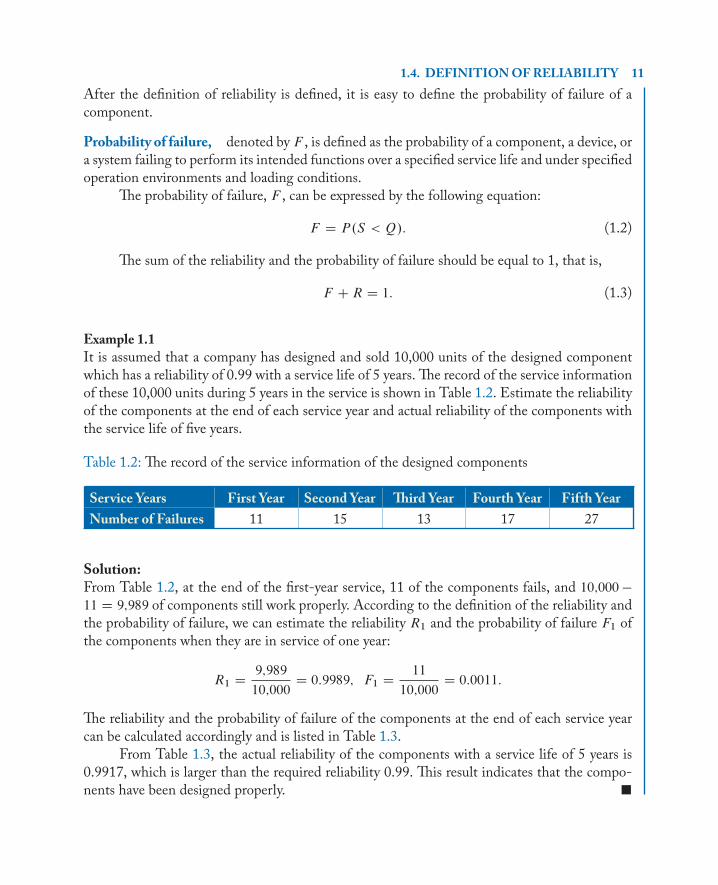
Example 1.1It is assumed that a company has designed and sold 10,000 units of the designed componentwhich has a reliability of 0.99 with a service life of 5 years. The record of the service informationof these 10,000 units during 5 years in the service is shown in Table 1.2. Estimate the reliabilityof the components at the end of each service year and actual reliability of the components withthe service life of five years.
Table 1.2: The record of the service information of the designed components
Service Years First Year Second Year ! ird Year Fourth Year Fifth Year
Number of Failures 11 15 13 17 27
Solution:From Table 1.2, at the end of the first-year service, 11 of the components fails, and 10;000 �
11 D 9;989 of components still work properly. According to the definition of the reliability andthe probability of failure, we can estimate the reliability R1 and the probability of failure F1 ofthe components when they are in service of one year:
R1 D9;989
10;000D 0:9989; F1 D
11
10;000D 0:0011:
The reliability and the probability of failure of the components at the end of each service yearcan be calculated accordingly and is listed in Table 1.3.
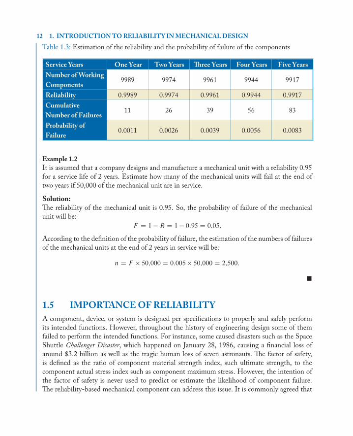
From Table 1.3, the actual reliability of the components with a service life of 5 years is0.9917, which is larger than the required reliability 0.99. This result indicates that the compo-nents have been designed properly. �
12 1. INTRODUCTIONTORELIABILITY INMECHANICALDESIGN
Table 1.3: Estimation of the reliability and the probability of failure of the components
Service Years One Year Two Years � ree Years Four Years Five Years
Number of Working
Components9989 9974 9961 9944 9917
Reliability 0.9989 0.9974 0.9961 0.9944 0.9917
Cumulative
Number of Failures 11 26 39 56 83
Probability of
Failure 0.0011 0.0026 0.0039 0.0056 0.0083
Example 1.2It is assumed that a company designs and manufacture a mechanical unit with a reliability 0.95for a service life of 2 years. Estimate how many of the mechanical units will fail at the end oftwo years if 50,000 of the mechanical unit are in service.
Solution:The reliability of the mechanical unit is 0.95. So, the probability of failure of the mechanicalunit will be:
F D 1 � R D 1 � 0:95 D 0:05:
According to the definition of the probability of failure, the estimation of the numbers of failuresof the mechanical units at the end of 2 years in service will be:
n D F � 50;000 D 0:005 � 50;000 D 2;500:
�
1.5 IMPORTANCEOFRELIABILITYA component, device, or system is designed per specifications to properly and safely performits intended functions. However, throughout the history of engineering design some of themfailed to perform the intended functions. For instance, some caused disasters such as the SpaceShuttle Challenger Disaster, which happened on January 28, 1986, causing a financial loss ofaround $3.2 billion as well as the tragic human loss of seven astronauts. The factor of safety,is defined as the ratio of component material strength index, such ultimate strength, to thecomponent actual stress index such as component maximum stress. However, the intention ofthe factor of safety is never used to predict or estimate the likelihood of component failure.The reliability-based mechanical component can address this issue. It is commonly agreed that
1.6. RELIABILITYHISTORY 13reliability in engineering design was initiated and established by the AGREE report [10] in1957. The method of reliability in engineering has become extremely important. The importanceof reliability in engineering design can be expressed and explained through the following fouraspects.
• Reliability in engineering design is a more scientific and advanced relative measure of thestatus of a component, device, or system. In reality, all design parameters such as ma-terial strength, working load, and component geometric dimensions have some inherentuncertainty. Per the definition of reliability, reliability considers all these uncertainties ofdesign parameters in engineering design and systematically links them together through aprobability theory to conduct engineering design.
• Reliability in engineering design is a more practical measure of the status of a component,device, or system because it admits that any designed component could fail no matter howwe design it. The reliability R is designed into the components per design specification, isan attribute of the component, and can be used to predict the percentage of failure of thedesigned component. The percentage of failure of the component will be equal to .1 � R/.
• Reliability is directly and tightly related to the reputation of a company and a product. Intoday’s competitive market, every device and system is expected to perform satisfactorilythroughout its expected life span. Usually, the value of reliability is proportional to theprice of the product. The higher reliability the product has, the higher the cost needed tomanufacture it. Product with higher reliability might affect company markets. However,the lower the reliability of the product indicates a higher percentage of failure. Althoughthe manufacturer gives a warranty to cover the failures of the product during its early stagesof life, too many failures during the warranty period not only cause inconvenience to thecustomer and high cost of repair to the manufacturer but also mean a loss of reputationand market share.
• Reliability in engineering design is a systematic tool for designing a complicated productor system with the required reliability. Generally, no device or system will perform reliablyunless it is designed specifically for reliability. The complicated system typically includesmany subsystems, and each subsystem can have thousands of components. Reliability inengineering design intends to design the reliability into each component or to predict thepercentage failure of each component. The proper arrangement or allocation of reliabilityinto each component can design each subsystem with the required reliability.
1.6 RELIABILITYHISTORYReliability in engineering design is an application of probability theory. Ancient mathematicianssuch as Italian mathematician Gerolamo Cardano in the 16th century, and French mathemati-cians Pierre de Fermat and Blaise Pascal in the 17th century, studied and researched probability
14 1. INTRODUCTIONTORELIABILITY INMECHANICALDESIGNtheory, which was mainly about gambling. However, the reliability in engineering emerged asa separate discipline in the 1950s due to the extensive research and study on military electronicequipment.
During World War II, Germans applied basic reliability concepts to improve the reliabil-ity of their V1 and V2 rockets [3]. The following are some unbelievable facts about electronicequipment during World War II [3].
• During 1941–1945, 60–75% of vacuum tubes in communication equipment failed.
• During 1941–1945, nearly 60% of the airborne equipment shipped to the Far East wasdamaged on arrival.
• During 1941–1945, nearly 50% of the spare parts and equipment in storage became un-serviceable before they were ever used.
• In 1947, nearly 70% of the electronic equipment possessed by the Navy was not operatingproperly.
Such extremely high percentages of electronic equipment failures, in reality, resulted ingreat attention and extensive research activities in the United States. In 1950, the Air Forceformed the ad hoc Group on Reliability of Electronic Equipment to study the situation andrecommend measures that could increase the reliability of equipment. In 1951, the Navy beganan extensive and lengthy study on vacuum tubes. In 1951, the Army started a similar investi-gation. Due to such an extensive study, in 1952, the Department of Defense established theAdvisory Group on Reliability of Electronic Equipment (AGREE) to coordinate the researchactivities of the Air Force, Navy, and Army. In June 1957, AGREE published its first report:“Reliability of Military Electronic Equipment” [10]. Two of their many conclusions and rec-ommendations in the AGREE report were: (1) reliability testing must be made an integral partin the development of a new system and (2) procuring agencies should accept the equipmentonly after getting the reliability demonstrated by a manufacturer. It is widely accepted that thisAGREE first report in 1957 is the foundation of the reliability in engineering design.
The extensive research on the reliability of electronic equipment in the 1950s formed thefirst set of reliability-related standards. Some examples of these military standards are listed inthe following.
• In 1952, the AGREE established a military standard MIL-STD-781 “Reliability Quali-fication and Production Approval Test,” which was revised as MIL-STD-781b in 1967.
• In 1955, the AGREE established military standards MIL-STD-441 “Reliability of Mil-itary Electronic Equipment.”
• In 1961, MIL-STD-756 for reporting prediction of weapons’ system reliability.
1.7. RELIABILITY VS. FACTOROF SAFETY 15• In 1965, the DOD (Department of Defense) military standard MIL-STD-785 “Reliabil-
ity Program for Systems and Equipment,” which was revised in 2008.
Reliability in mechanical engineering design is founded based on similar concepts andprinciples which were established through the extensive research on military electronic equip-ment. The following are several notable events for reliability in mechanical engineering design.
• In 1951, Weibull, W. of the Swedish Royal Institute of Technology published a statisticaldistribution for material strength [11]. This distribution is called Weibull distribution andhas played an important role in the development of reliability in mechanical engineering.
• In 1968, Professor Edward B. Haugen published the book Probability Approach to De-sign [12], which was directedly focused on mechanical design with reliability.
• In 1972, Professor A. D. S. Carter published a book Mechanical Reliability [13].
• In 1977, Dr. D. Kececioglu published a paper “Probabilistic design methods for reliabil-ity and their data and research requirements” to present the approach for dealing withreliability in fatigue failure [14].
Nowadays, reliability in engineering design has become an important concept and toolfor mechanical engineering design.
1.7 RELIABILITY VS. FACTOROF SAFETYThe differences between reliability and factor of safety will be very clear after Chapter 4 has beenread. Before that, we will use some simple examples to explain their differences.
In the traditional mechanical design approach, the factor of safety is typically defined asthe ratio of component’ strength to the maximum component stress induced by the operationalload. For example, if the failure mode of the component is a static failure, the factor of safety is:
n DS
Q> 1; (1.4)
where S is the average of the component’s strength index such as tensile yield strength or ul-timate tensile strength for static failure design. Q is the average of the component’s maximumstress, which can be determined by the component’s geometrical dimensions and operationalloading. n is the factor of safety, which links together component’s material strength, compo-nent geometrical dimensions, and operational loading for component design.
Reliability of a component is defined as the probability of a component, a device or asystem performing its intended functions without failure over a specified service life and underspecified operation environments and loading conditions. The mathematical equation for thereliability is shown in Equation (1.1) and is repeated here:
R D P.S � Q/; (1.1)
16 1. INTRODUCTIONTORELIABILITY INMECHANICALDESIGNwhere S is the component’s strength index such as tensile yield strength or ultimate tensilestrength for static failure design. Q is the component’s maximum stress, which can be deter-mined by the component’s geometrical dimensions and operational loading. R is reliability.
Both the reliability and the factor of safety serve the same purpose and are a measure forcreating the design equations. However, the key differences between them are:
• the factor of safety is a deterministic approach in which all design parameters are treatedas deterministic values. The factor of safety intends partially to consider the uncertainty ofthe design parameters; and
• the reliability is a probabilistic approach in which all design parameters are treated as ran-dom values. The uncertainties of the design parameters are assessed by reliability.
The following example can explain in detail the similarities and differences between thereliability and the factor of safety.
Example 1.3In the traditional design approach with a factor of safety, the design parameters for three designcases with different materials and different operation loading are treated as deterministic valuesand are listed in Table 1.4. When the uncertainties of the strengths and stresses of the threedesign cases are considered, the strengths and stresses of the components of the same designcases are treated as normal distribution random variables (note: the normal distribution willbe discussed in Section 2.12.4). The corresponding distribution parameters are also listed inTable 1.2:
1. conduct the design check, that is, calculate the factor of safety and the reliability of com-ponents; and
2. discuss the results.
Table 1.4: The design parameters of three design cases
Traditional Approach
with a Factor of Safety
! e Probabilistic Approach with a Reliability
Strength S
(normal distribution)
Stress Q
(normal distribution)
Case # Strength Stress Mean μSStandard
Deviation σSMean μQ
Standard
Deviation σQ
1 100 (ksi) 80 (ksi) 100 (ksi) 5 (ksi) 80 (ksi) 5 (ksi)
2 100 (ksi) 80 (ksi) 100 (ksi) 5 (ksi) 80 (ksi) 20 (ksi)
3 100 (ksi) 50 (ksi) 100 (ksi) 30 (ksi) 50 (ksi) 30 (ksi)
1.7. RELIABILITY VS. FACTOROF SAFETY 17Solution:
1. The factor of safety and the reliability.
The factor of safety of three design cases can be calculated per Equation (1.3) and arelisted in Table 1.5. The reliability can be calculated according to Equation (1.1), which willbe discussed in detail in Section 2.12.4. The random event .S � Q/ is the same randomevent .S � Q � 0/. Let us use Z to represent the new random variable S � Q, that is,Z D S � Q. Equation (1.1) can be rearranged as:
R D P .S � Q/ D P .S � Q � 0/ D P.Z � 0/:
Since both strength S and stress Q are normal distributions, the random variable Z willalso be a normal distribution. The mean �Z and standard deviation �Z of Z can be calcu-lated by the means and the standard deviations of S and Q. They are:
�Z D �S � �QI �Z D
q.�S /2
C��Q
�2:
After the mean and standard deviation of the normally distributed random variable Z aredetermined, the reliability can be directly calculated based on R D P.Z � 0/ and are listedin Table 1.5. (Note: The calculation procedure will be discussed in detail in Section 2.12.4.)
Table 1.5: The factor of safety and the reliability of three design cases
Case #
� e Factor of Safety Approach � e Reliability Approach
Strength Stress Factor of
Safety Mean μZ
Standard
Deviation σZReliability
1 100 (ksi) 80 (ksi) 1.25 20 (ksi) 7.1 (ksi) 0.9977
2 100 (ksi) 80 (ksi) 1.25 20 (ksi) 20.6 (ksi) 0.8340
3 100 (ksi) 50 (ksi) 2 50 (ksi) 42.4 (ksi) 0.8807
2. Discuss the results.
• Both the factor of safety and the reliability are the measure of the status of safetyof the components. However, the reliability R not only predicts the status of safetyof the component but also indicates failure probability F , which is equal to 1 � R.For example, from Table 1.5, the reliability of components in Case #1 is 0.9977, andthe failure probability of a component is 1 � 0:9977 D 0:0023 D 0:23%. The factor ofsafety cannot provide any information about the possible failure of a component.
18 1. INTRODUCTIONTORELIABILITY INMECHANICALDESIGN• From Table 1.5, both Cases #1 and #2 have the same factor of safety: 1.25. The same
value of the factor of safety implies that both Case #1 and Case #2 will have thesame measure of the status of safety. However, when the reliability approach is usedto check the status of safety of Case #1 and Case #2, the reliabilities of these twodesigns are quite different, as shown in Table 1.5. Case #1 has a reliability 0.9977,and Case #2 has a reliability 0.8340 only. The cause for this inconsistent result isdue to the uncertainty of design parameters. The traditional design approach withthe factor of safety cannot quantitively consider the effect of uncertainty. The designapproach with reliability does consider the effects of uncertainty.
• From Table 1.5, the factor of safety in the design Case #3 is 2 and is larger than thefactor of safety 1.25 of the designCase #1 from the table. According to themeaning offactor of safety, this indicates that the components from the design Case #3 should berelatively safer than the components from the designCase #1.However, the reliabilityof the components for the design Case #3 is much less than the reliability of thecomponent for the design Case #1 from Table 1.5. The cause for these contradictoryconclusions is mainly due to the uncertainty of design parameters. So, a higher factorof safety does not guarantee a much safer component. However, higher reliability willcertainly guarantee just that.
• From Table 1.4, the simple information about the design parameters, that is, deter-ministic values, are required when the design approach with a factor of safety is usedfor component design. However, when the design approach with reliability is usedfor component design, a large amount of information about design parameters areneeded because the type of distributions and corresponding distribution parametersare required. �
In summary, both the factor of safety and the reliability are the measure of the status ofsafety of a component. Both are successfully used for mechanical component design. The ad-vantages of the factor of safety are simple and do not require much information about designparameters. The disadvantages are: (1) it cannot be used to explain possible component failure;(2) the higher the factor of safety of components does not guarantee that it will be much safer;and (3) it cannot include the effects of uncertainty of the design parameters. The advantagesof reliability are: (1) it not only indicates the probability of safe components, but also indicatesthe probability of component failure; (2) the higher reliability of a component certainly guar-antees that it is much safer; and (3) the approach with reliability can fully consider the effectsof uncertainties of design parameters. The main disadvantage of the design approach with reli-ability is that much more information or a large amount of data about uncertainties of designparameters are required. Without reliable descriptions of uncertainties of design parameters, theimplementation of the design approach with reliability is meaningless.
1.8. SUMMARY 19
1.8 SUMMARYEngineering design is a process in which a design idea is checked for its feasibility, rephrased byengineering technical language, designed, and then manufactured into a product that will servethe society. The engineering design is a process not only because it takes a period of times to becompleted, but also because the prototype of design must be built and fully tested before it canbe released to the society. One description of the engineering design process is the five-phaseengineering design process—Phase One: Needs Assessment; Phase Two: Design Specifications;Phase Three: Conceptual Designs, Phase Four: Detailed Design; and Phase Five: Implementa-tion. The contents of this book are the key techniques required to design components in PhaseFour: Detailed Design.
Reliability R is defined as the probability of a component, a device or a system performingits intended functions without failure over a specified service life and under specified operationenvironments and loading conditions. The reliability-based mechanical design is the main topicof this book. It uses the reliability to replace the factor of safety to form a design governingequation for linking all design parameters together. One dilemma for the traditional designtheory with the factor of safety in mechanical component design is that it cannot provide anytool to assess the component failure, which is a reality in industries. The reliability-based me-chanical design is an advanced design theory and can provide a tool to solve this dilemma. Afew highlights about the reliability-based mechanical design are follows.
• All main design parameters such as materials strengths, component dimensions, externalloadings, and the loading-induced component stresses are treated as random variables forconsidering their uncertainties.
• The component is designed with required reliability. Its physical meaning is the percent-age of components working properly under specified operation environments and loadingconditions over a specified service life.
• Probability of failure F of the component will be .1 � R/ and indicates the percentageof components which cannot work properly under specified operation environments andloading conditions over a specified service life.
• The higher the reliability a component has, the safer it will be. However, the higher relia-bility of a component also implies a higher cost of the component.
1.9 REFERENCES[1] Voland, G., Engineering by Design, Pearson Prentice Hall, 2004. 2, 5
[2] Le, Xiaobin, Anthony, D., Roberts, R., and Moazed, A., Instructional methodologyfor capstone senior mechanical design, ASEE International Conference, Vancouver, BC,Canada, June 26–29, 2011. 2
20 1. INTRODUCTIONTORELIABILITY INMECHANICALDESIGN[3] Rao, S. S., Reliability Engineering, Pearson, 2015. 7, 8, 9, 14
[4] Reliability analysis center, non-electronic parts reliability data, NPRD-1, ReliabilityAnalysis Center, Rome Development Center, Griffiss Air Force Base, New York, 1978.7, 8
[5] Cater, A. D. S., Mechanical Reliability and Design, John Wiley & Sons, Inc., New York,1997. 8
[6] Modarres, M., Kaminskiy,M., and Krivtson, V.,Reliability Engineering andRisk Analysis:A Practical Guide, 2nd ed., CRC Press, 2010. DOI: 10.1201/9781420008944.
[7] Dasgupta, A. and Pecht, M., Materials failure mechanisms and damage models, IEEETransactions on Reliability, 40(5), 531–536, 1991. DOI: 10.1109/24.106769. 8
[8] Choi, S.-K., Grandhi, R. V., and Canfield, R. A., Reliability-based structural design.DOI: 10.1007/978-1-84628-445-8. 9
[9] Vinogradov, O., Introduction to Mechanical Reliability, a Designer’s Approach, HemispherePublishing Corporation, 1991. 9
[10] AGREE Report, Advisory Group on Reliability of Electronic Equipment (AGREE),Reliability ofMilitary Electronic Equipment,Office of theAssistant Secretary ofDefense(Research and Engineering), Department of Defense, Washington, DC, 1957. 13, 14
[11] Weibull, W., A statistical distribution function of wide applicability, Journal of ApplicationMechanics Transactions on ASME, 18(3): 293–297, 1951. 15
[12] Haugen, E. B., Probability Approach to Design, New York, Wiley, 1968. 15
[13] Carter, A. D. S., Mechanical Reliability, New York, Wiley, 1972. DOI: 10.1007/978-1-349-18478-1. 15
[14] Kececioglu, D., Probabilistic design methods for reliability and their data and researchrequirements, Failure Prevention and Reliability, ASME, pp. 285–305, 1977. 15
1.10 EXERCISES1.1. List at least two different definitions of engineering design and discuss their similarities
and differences.
1.2. Use your statement to explain what engineering design is.
1.3. What is the five-phase engineering design? What are the main tasks of each phase?
1.10. EXERCISES 211.4. Use one of your design projects to check whether you used all five phases. If not, why
or what happened?
1.5. Why is the engineering design a process?
1.6. List at least two possible needs for engineering design and then run the needs assess-ment.
1.7. Use one of your design examples to describe how you conduct a conceptual design.
1.8. List four examples of failures that you know.What are the types of failures?What causesfailures?
1.9. Describe and explain your understanding of a typical bathtub curve of the failure rate.
1.10. What is a static strength failure?
1.11. What is fatigue failure? Explain the differences between static failure and fatigue failure.
1.12. List one example of excessive deflection failure and provide some possible solutions todeal with the issue.
1.13. What is uncertainty in engineering? List and explain at least three examples of typicaldesign parameters.
1.14. What causes the uncertainty of the ultimate tensile strength of a material?
1.15. Explain the uncertainty related to geometrical dimensions of components.
1.16. Use one example to describe and explain uncertainty related to component failures.
1.17. What is the factor of safety? What is the physical meaning of the factor of safety? Canyou use the factor of safety to predict the component failure? Why?
1.18. List and explain the definition of reliability in engineering design.
1.19. What are the similarities and differences between the factor of safety and reliability?
1.20. What is the reliability-based mechanical design? What are the key differences betweenthe traditional mechanical design theory and reliability-based mechanical design?
1.21. Does a component with a higher factor of safety imply that the component will havehigher reliability? If not, can you explain it?
1.22. Describe and explain the importance of reliability in engineering design.
1.23. Briefly describe the reliability history. What do you learn from this history?
![Failure Modes, Effects and Diagnostic · PDF fileReliability Handbook, 4th Edition, 2017 LLC, Electrical Component Reliability Handbook, Fourth Edition, 2017 [N3] Mechanical Component](https://img.pdfslide.net/doc/110x75/5a78b8487f8b9ae6228bfe2f/failure-modes-effects-and-diagnostic-handbook-4th-edition-2017-llc-electrical.jpg)