Embed Size (px)
Citation preview
Reliability Demonstration Approach forAdvanced Stirling Radioisotope Generator
Chuong Ha 1
Lockheed Martin Space Systems, Sunnyvale, CA, 94089
Edward Zampino2
NASA Glenn Research Center, Cleveland, OH, 44135
Barry Penswick3
Sunpower, Athens, OH, 45701
and
Michael Spronz4
Sest Inc., Cleveland, OH, 44135
Developed for future space missions as a high-efficiency power system, the AdvancedStirling Radioisotope Generator (ASRG) has a design life requirement of 14 yr in spacefollowing a potential storage of 3 yr after fueling. In general, the demonstration of long-lifedynamic systems remains difficult in part due to the perception that the wearout of movingparts cannot be minimized , and associated failures are unpredictable. This paper shows acombination of systematic analytical methods, extensive experience gained from technologydevelopment, and well-planned tests can be used to ensure a high level reliability of ASRG.With this approach, all potential risks from each life phase of the system are evaluated andthe mitigation adequately addressed. This paper also provides a summary of important testresults obtained to date for ASRG and the planned effort for system-level extendedoperation.
Nomenclature
ac = Alternating CurrentACU = Advanced Controller UnitASC = Advanced Stirling ConvertorASRG = Advanced Stirling Radioisotope GeneratorCSAF = Cold Side Adapter Flangedc = Direct CurrentFEA = Finite Element AnalysisFMECA = Failure Modes, Effects, and Criticality AnalysisFTA = Fault Tree AnalysisGHA = Generator Housing AssemblyGPHS = General Purpose Heat SourcePRD = Pressure Relief DeviceSDM = System Dynamic ModelSRG = Stirling Radioisotope Generator TDC = Technology Demonstration Convertor
1 Reliability Engineer Sr. Staff, 1111 Lockheed Martin Dr., MS O7/LMS B/157, Sunnyvale, CA 94089.2Reliability Engineering Lead, Program and Project Assurance, 21000 Brookpark Rd., MS 5–4, Cleveland, OH44135.3Reliability Consultant, Sunpower Inc., 182 Mill St., Athens, OH 45701.4QA Engineer Sr., Sest Inc., 18151 Jefferson Park Road, Suite 101, Middleburg Heights, OH 44130.
American Institute of Aeronautics and Astronautics
https://ntrs.nasa.gov/search.jsp?R=20100040438 2018-07-09T14:19:48+00:00Z
I. Introduction
THE ASRG is being developed by the Department of Energy and NASA 1 as a highly efficient power system forpotential use in future space exploration missions, including deep space missions and surface applications. With
the engineering development phase complete in 2008, 2 the qualification design effort is well underway for flightreadiness. One of the key requirements of the ASRG is the capability to perform its functions for a 17-yr design lifewith a probability of success of at least 90%. The required design life consists of a 14 yr operation in spacefollowing a potential storage of 3 yr in controlled environments after fueling. While this design life is typical fordeep space mission systems as well as for commercial satellites, reliability demonstration for onboard continuouslyrunning mechanisms remains a key challenge. For example, attitude control subsystems of spacecraft such as gyrosand momentum wheels could reach between 3000 to 8000 rpm. In the case of the Advanced Stirling Convertor(ASC) units of the ASRG, the moving free-piston and displacer subsystem operates at about 102 Hz. Thus, for a 17-yr design life the total number of cycles is predicted to reach 55 billion (5.5 x 10 10). Clearly, a system testing at suchlong duration and high cycle levels is impractical. Instead, extensive knowledge accumulated throughout thedevelopment years has led to these key observations:
- ASRG reliability demonstration cannot be based exclusively on a single, classic life test but must rely on acombination of analytical models and alternative tests.
- Moving parts only represent one aspect of the complete ASRG functionality. Any potential life-limitingrisks from moving parts as well as other subsystems must be thoroughly understood and adequatelymitigated.
- Random and wearout failures are applicable to specific life phases of the design and must be tackleddifferently.
- Capability to simulate subsystem interface and performance in all expected operating conditions is essentialto ensure mission success.
- Well-planned qualification and accelerated testing at component or subsystem levels can also providevaluable data for reliability modeling and demonstration.
II. ASRG Design
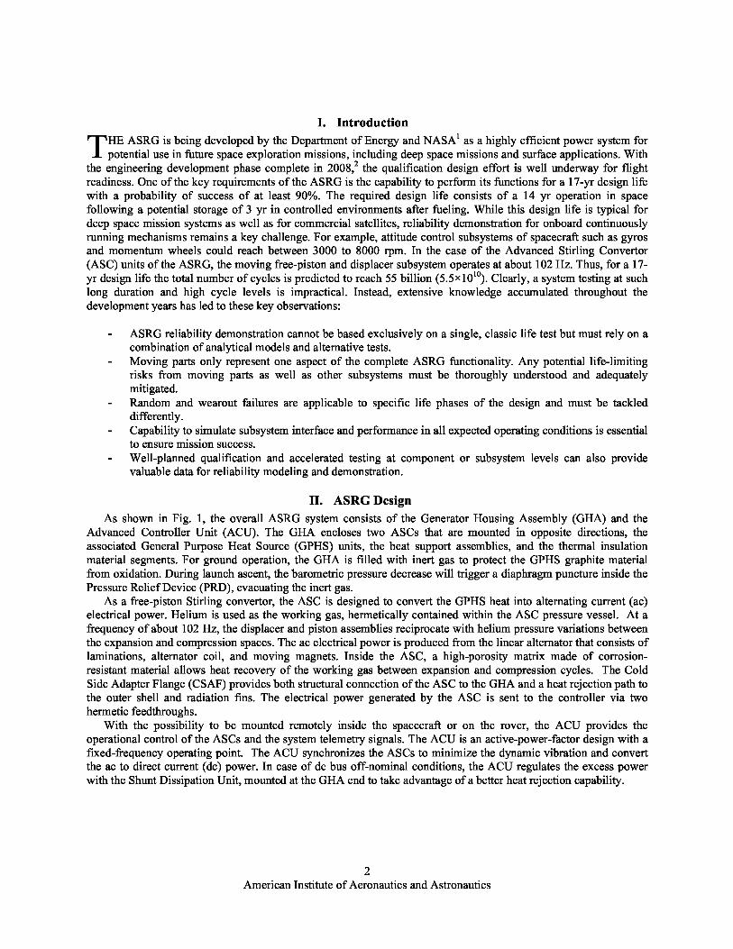
As shown in Fig. 1, the overall ASRG system consists of the Generator Housing Assembly (GHA) and theAdvanced Controller Unit (ACU) . The GHA encloses two ASCs that are mounted in opposite directions, theassociated General Purpose Heat Source (GPHS) units, the heat support assemblies, and the thermal insulationmaterial segments . For ground operation, the GHA is filled with inert gas to protect the GPHS graphite materialfrom oxidation . During launch ascent, the barometric pressure decrease will trigger a diaphragm puncture inside thePressure Relief Device (PRD), evacuating the inert gas.
As a free-piston Stirling convertor, the ASC is designed to convert the GPHS heat into alternating current (ac)electrical power. Helium is used as the working gas, hermetically contained within the ASC pressure vessel. At afrequency of about 102 Hz, the displacer and piston assemblies reciprocate with helium pressure variations betweenthe expansion and compression spaces. The ac electrical power is produced from the linear alternator that consists oflaminations, alternator coil, and moving magnets. Inside the ASC, a high-porosity matrix made of corrosion-resistant material allows heat recovery of the working gas between expansion and compression cycles. The ColdSide Adapter Flange (CSAF) provides both structural connection of the ASC to the GHA and a heat rejection path tothe outer shell and radiation fins. The electrical power generated by the ASC is sent to the controller via twohermetic feedthroughs.
With the possibility to be mounted remotely inside the spacecraft or on the rover, the ACU provides theoperational control of the ASCs and the system telemetry signals. The ACU is an active-power-factor design with afixed-frequency operating point. The ACU synchronizes the ASCs to minimize the dynamic vibration and convertthe ac to direct current (dc) power. In case of dc bus off-nominal conditions, the ACU regulates the excess powerwith the Shunt Dissipation Unit, mounted at the GHA end to take advantage of abetter heat rejection capability.
2American Institute of Aeronautics and Astronautics
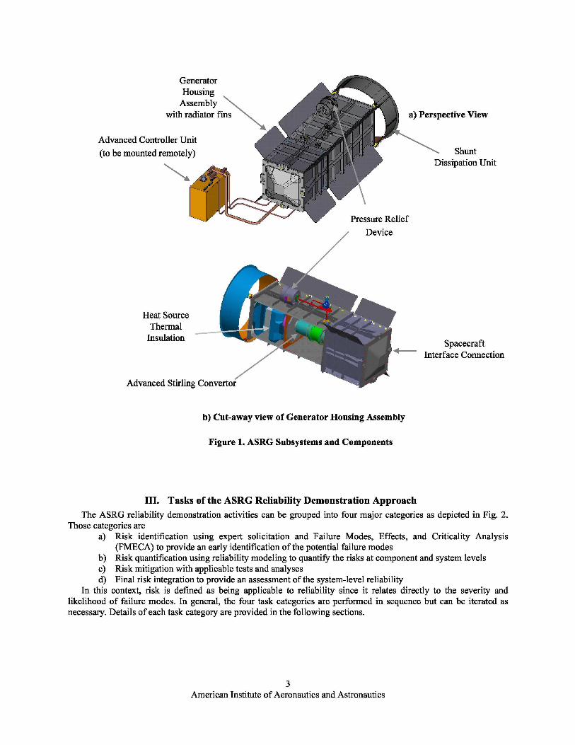
Figure 1. ASRG Subsystems and Components
III. Tasks of the ASRG Reliability Demonstration Approach
The ASRG reliability demonstration activities can be grouped into four major categories as depicted in Fig. 2.Those categories are
a) Risk identification using expert solicitation and Failure Modes, Effects , and Criticality Analysis(FMECA) to provide an early identification of the potential failure modes
b) Risk quantification using reliability modeling to quantify the risks at component and system levelsc) Risk mitigation with applicable tests and analysesd) Final risk integration to provide an assessment of the system -level reliability
In this context, risk is defined as being applicable to reliability since it relates directly to the severity andlikelihood of failure modes. In general, the four task categories are performed in sequence but can be iterated asnecessary. Details of each task category are provided in the following sections.
American Institute of Aeronautics and Astronautics
Figure 2. Tasks of the ASRG Reliability Demonstration
A. Risk IdentificationAt the beginning of the ASRG program , when design details were still evolving in many areas, the development
team decided that a risk identification process must be implemented and maintained regularly. In steps with thedesign activity progress, this effort would identify any life-limiting risks and keep track of mitigation actions. Therisk identification process has benefited significantly from inputs of experts at NASA Glenn Research Center,NASA Jet Propulsion Laboratory, Sunpower, and Lockheed Martin. Insights from the designers also formed avaluable understanding of the system characteristics. Using the FMECA technique, the potential failure modes ofeach component and associated impacts were systematically identified . The failure mode severity is ranked based onthree simple qualitative levels: 1) no impacts on power performance; 2) reduced or degraded power performance;and 3) imminent or catastrophic loss of power performance. In terms of likelihood ranking, the five-level systemfrom MIL–STD–1629A 3 was adopted to allow the necessary resolution. In this system, the highest value (5)represents a frequent occurrence while the lowest value (1) represents an unlikely one. The failure mode criticality isthen calculated as Severity times Likelihood. As output, the FMECA provides a criticality matrix that involves allcomponents in the system. Critical items considered as potential single point failures are clearly listed formonitoring and mitigating.
B. Risk Quantification With Reliability ModelsFollowing the risk identification process with FMECA, we generated the reliability models for both components
and the full system to quantify the risks. Usually, the component reliability models are not needed because thederivation of failure probability relies on analysis of existing test results and usage history. Most of the electronicparts have established standard methods and vendor database for their qualification analysis. However, when thedesign is new or only limited test data are available, some iteration is required. Several reliability component modelsmust have initially utilized similar equipment data and then gradually switched to actual data as qualification oraccelerated tests were completed. In other instances, the component reliability models were generated using FiniteElement Analysis (FEA) for stress -strength interference prediction . Most of these FEA models applied to structuralcomponents. When the design data was available, the component reliability models took into account the relevantuncertainties from design and operating condition parameters. As data from the qualification and accelerated testsbecame available, the stress-strength interference predictions were updated accordingly.
At the system level, we preferred the Fault Tree Analysis (FTA) model to integrate the results obtained from thecomponent analysis process described previously. In order to generate the fault tree logic, a review of eachsubsystem FMECA (ACU, ASC, and GHA) and the system spec requirements was necessary. Information from theFMECA provides input to build the basic failure events and the spec requirements to construct the fault logic. TheFTA model details were updated as needed providing the risk drivers and contributions from components andsubsystems at periodic reviews.
4American Institute of Aeronautics and Astronautics
C. Component and Subsystem Accelerated TestsMany of the ASRG components are qualified with accelerated testing. These tests not only validate the design
margins but also provide inputs to the reliability analyses. However, due to the fundamental operating characteristicsof the free piston—linear alternator configuration of the ASC—it is extremely difficult to carry out the classicalapproach of employing various accelerated testing at the full system. The primary cause of this limitation is therelatively narrow operating envelope of the Stirling engine from the viewpoint of operating speed (frequency),mechanical loads (pressure), electrical loads (alternator capabilities), and temperatures (heater head creep, magnetdegradation, etc.), leaving little if any parameters available for system accelerated testing.
To overcome this fact, the development team has employed risk mitigation effort for a wide range of componenttests to define their key durability and reliability characteristics under normal and extreme load conditions. Thefollowing table provides a set of such testing efforts.
Table 1. Component Accelerated Tests.
Component Type Purpose Results
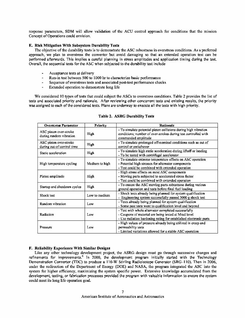
Verify creep rate at 1.4 timesInterim measured creep rate at half of
Heater head nominal peak internal pressurepredicted value
and 869 °C max. temperaturePermeability test of thin wall
Heater head specimens at 850 °C and 6% No leakage foundstrain
FastenersUse destruction torque to verify Each fastener type was tested with 30nut factor and joint load capacity samples—high strength results obtainedMagnet bonding material aging
No significant changes at 2 yr aging inOrganics
characterization with exposureterms of weight change and mechanical
up to 1.8 times nominalproperties
operating temperatureGamma irradiation tests of Large margins for operating conditions
Organics organics used in the ASC at 5, confirmed—ongoing tests10, and 15 MradDetermine maximum
The onset temperature of nonrecoverableLinear alternator temperature for onset
degradation determineddemagnetization
High margin results obtained with step-
Displacer spring Verify fatigue endurancestress tests—additional tests with constantstress method ongoing—spring materialto be tested at giga cycles level
Verify hermeticity withFive different model samples tested;
increasing temperature up to 4ceramic seal selected over glass;
Power feedthrough times nominal operatingadditional tests with elevated temperatureand axial loads also show very high
temperaturemargins
Verify long-term shrinkage of Interim data at 8000 hr collected—Insulation material samples at max. temperature shrinkage ranging from 2 to 10%
950 °C depending on insulation layer temperature
In Table 1, it is significant to note that- Most of the ASC fasteners are 2 mm in size; therefore , extremely small by conventional structural
standards and in a number of cases represent potential single point failures. This size characteristicrequired a master buy of fasteners along with extensive testing for both the fastener material as well asthe installation torque for all operating conditions. This latter effort required a careful test planning tosimulate mechanical joints of the convertor since a wide range of materials are employed.
- Linear alternator design limits are critical to defining the safe operating conditions for this criticalcomponent. A unique test rig, called a Hot Alternator Test Rig (Fig. 4), was employed in this process.The test rig allows the test ASC alternator to be driven at various amplitudes and power levels while
American Institute of Aeronautics and Astronautics
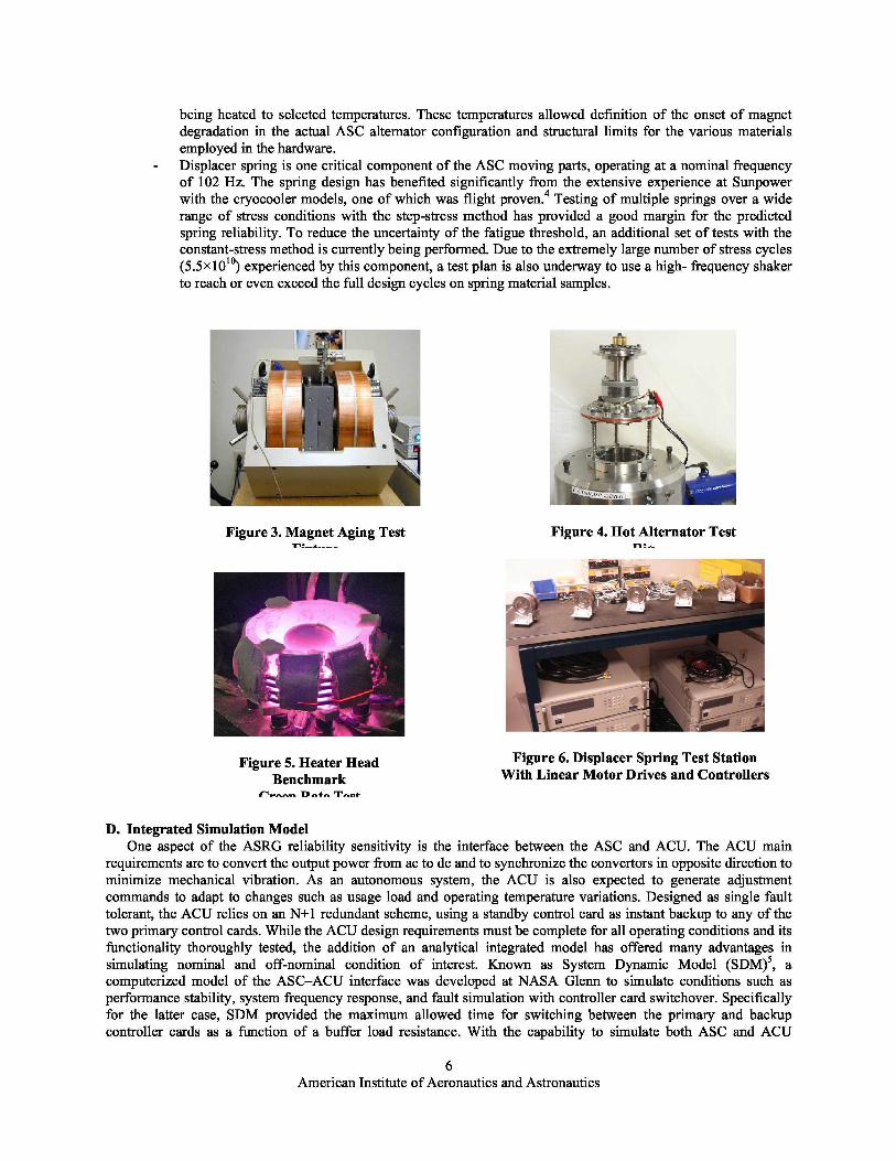
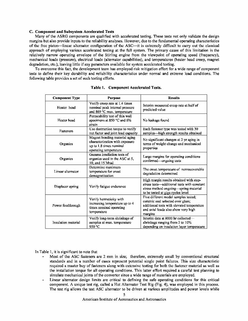
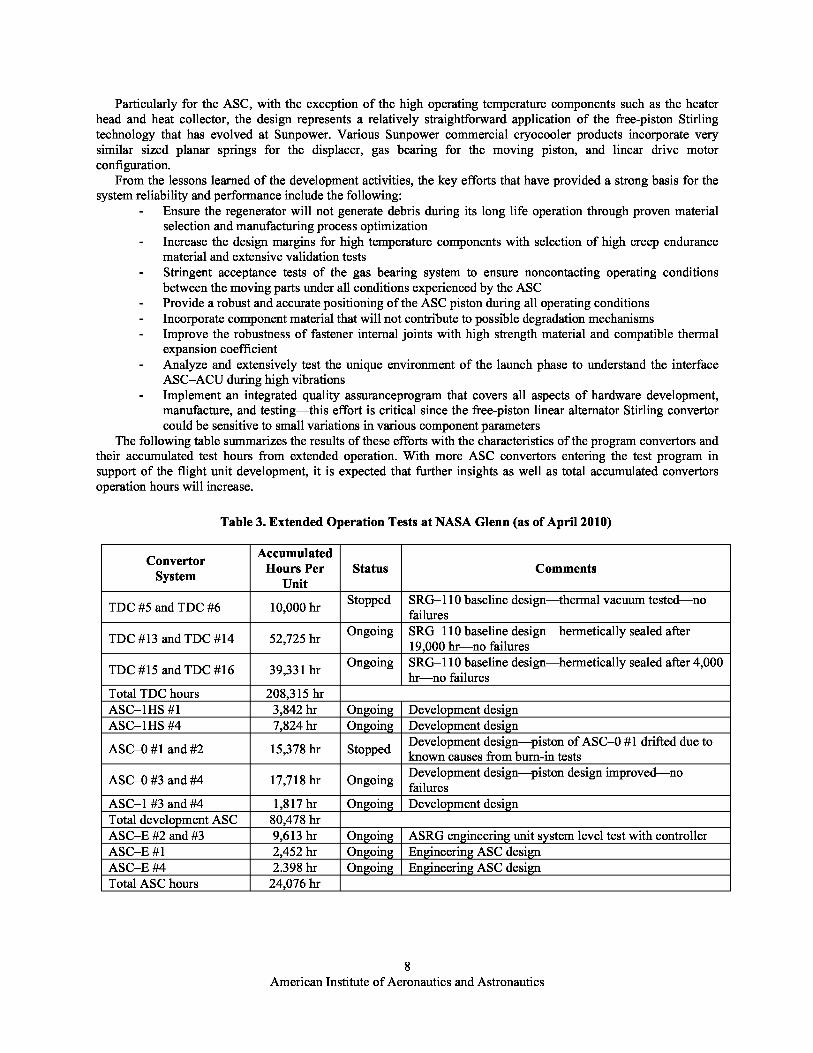
being heated to selected temperatures. These temperatures allowed definition of the onset of magnetdegradation in the actual ASC alternator configuration and structural limits for the various materialsemployed in the hardware.Displacer spring is one critical component of the ASC moving parts, operating at a nominal frequencyof 102 Hz. The spring design has benefited significantly from the extensive experience at Sunpowerwith the cryocooler models, one of which was flight proven. 4 Testing of multiple springs over a widerange of stress conditions with the step-stress method has provided a good margin for the predictedspring reliability. To reduce the uncertainty of the fatigue threshold, an additional set of tests with theconstant-stress method is currently being performed. Due to the extremely large number of stress cycles(5.5×10 10) experienced by this component, a test plan is also underway to use a high- frequency shakerto reach or even exceed the full design cycles on spring material samples.
Figure 3. Magnet Aging Test
Figure 4. Hot Alternator TestFi t re Ri
Figure 5. Heater Head Figure 6. Displacer Spring Test Station
Benchmark With Linear Motor Drives and Controllers
Creep Rate Test
D. Integrated Simulation ModelOne aspect of the ASRG reliability sensitivity is the interface between the ASC and ACU. The ACU main
requirements are to convert the output power from ac to dc and to synchronize the convertors in opposite direction tominimize mechanical vibration. As an autonomous system, the ACU is also expected to generate adjustmentcommands to adapt to changes such as usage load and operating temperature variations. Designed as single faulttolerant, the ACU relies on an N+1 redundant scheme, using a standby control card as instant backup to any of thetwo primary control cards. While the ACU design requirements must be complete for all operating conditions and itsfunctionality thoroughly tested, the addition of an analytical integrated model has offered many advantages insimulating nominal and off-nominal condition of interest. Known as System Dynamic Model (SDM) 5, acomputerized model of the ASC –ACU interface was developed at NASA Glenn to simulate conditions such asperformance stability, system frequency response, and fault simulation with controller card switchover. Specificallyfor the latter case, SDM provided the maximum allowed time for switching between the primary and backupcontroller cards as a function of a buffer load resistance. With the capability to simulate both ASC and ACU
6American Institute of Aeronautics and Astronautics
response parameters, SDM will allow validation of the ACU control approach for conditions that the missionConcept of Operations could envision.
E. Risk Mitigation With Subsystem Durability TestsThe objective of the durability tests is to demonstrate the ASC robustness in overstress conditions. As a preferred
approach, we plan to overstress the convertor but avoid damag ing so that an extended operation test can beperformed afterwards. This implies a careful planning in stress amplitudes and application timing during the test.Overall, the sequential tests for the ASC when subjected to the durability test include
- Acceptance tests at delivery- Run-in test between 500 to 1000 hr to characterize basic performance- Sequence of overstress tests and associated post-test performance checks- Extended operation to demonstrate long life
We considered 10 types of tests that could subject the ASCs to overstress conditions. Table 2 provides the list oftests and associated priority and rationale. After reviewing other concurrent tests and existing results, the prioritywas assigned to each of the considered tests. Plans are underway to execute all the tests with high priority.
Table 2. ASRG Durability Tests
Overstress Parameter Priority Rationale
ASC piston over-stroke- To simulate potential piston collisions during high vibration
during random vibration High conditions; number of over-strokes during test controlled withcommanded amplitude
ASC piston over-stroke High - To simulate prolonged off-nominal conditions such as out ofduring out-of-control time control or switchover
Static acceleration High- To simulate high static acceleration during liftoff or landing- To be tested with centrifugal accelerator- To simulate extreme temperature effects on ASC operation
High temperature cycling Medium to high - Potential high stresses for alternator components- Test could be combined with extended operation- High stress effects on most ASC components
Piston amplitude High - Moving parts subjected to accelerated stress factor- Test could be combined with extended operation
Startup and shutdown cycles High- To ensure the ASC moving parts robustness during variousground operation and tests before final fuel loading
Shock test Low to medium- Shock tests already being planned for system qualification- Engineering system successfully passed 3000 g shock test
Random vibration Low- Tests already being planned for system qualification- Some past tests went to qualification level and beyond- Test with whole alternator completed successfully
Radiation Low - Coupons of material are being tested at Mrad level- Use radiation hardening rating for established electronic parts- High values of pressure already being utilized in creep and
Pressure Low permeability tests- Limited variations allowed for a stable ASC operation
F. Reliability Experience With Similar DesignsLike any other technology development project, the ASRG design must go through successive changes and
refinements for improvements. 6 In 2000, the development program initially started with the TechnologyDemonstration Convertor (TDC) to produce a 110-W Stirling Radioisotope Generator (SRG–110). Then in 2006,under the redirection of the Department of Energy (DOE) and NASA, the program integrated the ASC into thesystem for higher efficiency, maximizing the system specific power. Extensive knowledge accumulated from thedevelopment, testing, or fabrication processes provided the program with valuable information to ensure the systemcould meet its long life operation goal.
7American Institute of Aeronautics and Astronautics
Particularly for the ASC, with the exception of the high operating temperature components such as the heaterhead and heat collector, the design represents a relatively straightforward application of the free-piston Stirlingtechnology that has evolved at Sunpower. Various Sunpower commercial cryocooler products incorporate verysimilar sized planar springs for the displacer, gas bearing for the moving piston, and linear drive moto rconfiguration.
From the lessons learned of the development activities, the key efforts that have provided a strong basis for thesystem reliability and performance include the following:
- Ensure the regenerator will not generate debris during its long life operation through proven materialselection and manufacturing process optimization
- Increase the design margins for high temperature components with selection of high creep endurancematerial and extensive validation tests
- Stringent acceptance tests of the gas bearing system to ensure noncontacting operating conditionsbetween the moving parts under all conditions experienced by the ASC
- Provide a robust and accurate positioning of the ASC piston during all operating conditions- Incorporate component material that will not contribute to possible degradation mechanisms- Improve the robustness of fastener internal joints with high strength material and compatible thermal
expansion coefficient- Analyze and extensively test the unique environment of the launch phase to understand the interface
ASCÐACU during high vibrations- Implement an integrated quality assuranceprogram that covers all aspects of hardware development,
manufacture, and testing—this effort is crit ical since the free-piston linear alternator Stirling convertorcould be sensitive to small variations in various component parameters
The following table summarizes the results of these efforts with the characteristics of the program convertors andtheir accumulated test hours from extended operation. With more ASC convertors entering the test program insupport of the flight unit development, it is expected that further insights as well as total accumulated convertorsoperation hours will increa se.
Table 3. Extended Operation Tests at NASA Glenn (as of April 2010)
Convertor Accumulated
System Hours Per Status CommentsUnit
TDC #5 and TDC #6 10,000 hrStopped SRGÐ110 baseline design—thermal vacuum tested—no
failures
TDC #13 and TDC #14 52,725 hrOngoing SRGÐ110 baseline design—hermetically sealed after
19,000 hr—no failures
TDC #15 and TDC #16 39,331 hrOngoing SRGÐ110 baseline design—hermetically sealed after 4,000
hr—no failuresTotal TDC hours 208,315 hrASCÐ1HS #1 3,842 hr Ongoing Development designASCÐ1HS #4 7,824 hr Ongoing Development design
ASCÐ0 #1 and #2 15,378 hr StoppedDevelopment design —piston of ASCÐ0 #1 drifted due toknown causes from burn-in tests
ASCÐ0 #3 and #4 17,718 hr OngoingDevelopment design —piston design improved—nofailures
ASCÐ1 #3 and #4 1,817 hr Ongoing Development designTotal development ASC 80,478 hrASCÐE #2 and #3 9,613 hr Ongoing ASRG engineering unitsystem level test with controllerASCÐE #1 2,452 hr Ongoing Engineering ASC designASCÐE #4 2.398 hr Ongoing Engineering ASC designTotal ASC hours 24,076 hr
American Institute of Aeronautics and Astronautics
G. Integrated System Extended OperationTraditionally, we use the extended operation (life test) to demonstrate the integrated design has eliminated
potential random failures and wearout risks. These failure modes are applicable to the mid- and late-life phases ofthe system, rather than the early -life phase because infant mortality failures can be mitigated by extensive burn-inand qualification tests. Unlike the durability tests previously described, the extended operation tests drive theintegrated system at nominal operating conditions for a target duration or as long as possible. It should beemphasized that life test , while very important, is not the only reliability measure of the system. Other componenttest data and analytical model results must be considered to arrive at a complete reliability prediction. As tocomplement other efforts, the focus of the extended operation is also on detecting failure modes and operationanomalies at the system level unforeseen by other analyses and tests.
For ASRG, the 17-yr design life and continuous high cycle level operation have made impractical a full life teston the same test unit. Sensitivity calculations using the Weibull model 7 to reach the reliability target solely through azero-failure life test plan, have led to sample size and test time that far exceed any program resources. Moreover,even a relaxation in confidence level (lower than 90%) gave little relief on test duration. Instead, we adopt thefollowing approach for life test:
- Since the design has no contacts on moving parts, the random failure modes are assessed as moredominant contributors than the wearout failure modes during the entire system life. Random failures areindependent of time and therefore the test duration target can be cumulative from a number of systemsunder test.
- Based on the recommendation of aerospace standardsfor movingmechanism, 8 the cumulative testduration goal is to achieve 1.5 times design life (or 25.5 yr). For a potential 2015 launch target, this goalis achievable with high confidence, using at least six systems (each with two ASCs), three of which willstart in early 2011, and the remaining in early 2012. The estimated total accumulated hours from theASCs of these six systems will reach 38 yr or larger than 2 times design life.
- Considering the insights gained from the existing life tests, the test duration from 4 to 5 yr would besufficient to uncover any life-limiting risks.
- To address the wearout and degradation concerns, we rely on the accelerated tests of components anddurability tests (described previously) . For moving parts particularly, even if the traditional life testapproach could be carried out, a very large amount of accrued test time might be requ ired due to the no-contact design characteristics. Instead, it is better to perform durability tests that simulate overstressconditions that might lead to the potential rubbing and subsequent debris generation. Certainly,workmanship and quality assurance control of the high dimension tolerances also help to ensure a longlife operation.
- For each system in the extended operation life test, we have recommended to use an integrated ASC–ACU configuration. Even interim versions of the ACU before flight could provide a betterunderstanding of the interface between the two subsystems. The objective of the ACU presence is notabout electronic parts life testing but to understand the interface and to characterize all operatingconditions.
H. Reliability Prediction With FTA System ModelThe final step of reliability demonstration is to integrate the risks and interpret the results. As a probabilistic
analysis, one could use either the Reliability Block Diagram or the FTA technique. In order to have a completeintegration of risks derived from test results and analyses described above, we generated a system FTA model topredict the reliability. With sufficient knowledge and relevant test data, the typical FTA is a straightforward andsystematic top-down method to provide both the overall system reliability and individual contributions at subsystemor component levels. The FTA model also provides the overall risk ranking and the list of cutsets or potentialcombination of failure events that lead to the top event. For specific mission phases and scenarios of interest, a seriesof conditional fau lt and event trees are necessary to determine the specific risks.
IV. Conclusion
The reliability demonstration approach for ASRG includes a series of steps that involve both analytical modelingand tests. The extensive knowledge accumulated throughout the development years allows not only a full systemcharacterization but also a practical approach to test the long life requirement. As key to mission success, the risksassociated with each life phase of the system must be understood and associated tests adequately planned. We alsobelieve that like any other design, inherit and usage reliability are covered by sound design and good workmanship.
9American Institute of Aeronautics and Astronautics
Acknowledgments
The work described in this paper was sponsored by the U.S. Department of Energy and the National Aeronauticsand Space Administration. The authors wish to acknowledge the contribution and technical collaboration made byother members of the ASRG Reliability Integrated Product Team.
References1 Chan, J., Wood, J. G., and Schreiber, J. G., “Development of Advanced Stirling Radioisotope Generator for Space
Exploration,” NASA/TMÑ2007-214806, 2007.2Chan, J., Hill, D., Hoye, T., and Leland, D., “Development for Advanced Stirling Radioisotope Generator for P lanetry
Surface and Deep Space Missions,” Proceedings of the 6th International Energy Conversion Engineering Conference, AIAAÐ2008–5790, Cleveland, OH, 2008.
3Military Standard, “Procedures for Performing a Failure Mode, Effects, and Criticality Analysis,” MILÐSTDÐ1629, Rev. A,1980.
4Wood, J. G., Wilson, K., Carroll, C., Matejczyk, D., Soender, E., and Penswick, L. B., “Advanced Stirling Convertor PhaseII Achievements and Planned Phase III Efforts,” 4th International Energy Conversion Engineering Conference, AIAA, 2006 Ð4108.
5Regan, T., “Free-Piston Stirling Convertor Controller Development at NASA Glenn Research Center,” NASA/CRÑ2004-213038, 2004.
6Wong, W. A., Wood, J. G., and Wilson, K., “Advanced Stirling Convertor (ASC)—From Technology Development toFuture Flight Product,” NASA/TMÑ2008-215282, 2008.
7Abernathy, R. B., “The New Weibull Handboook,” Fifth Edition, Abernathy , 2004.8AIAA Standard, “Moving Mechanical Assemblies for Space and Launch Vehicles,” AIAA S–114–2005.
10American Institute of Aeronautics and Astronautics