Embed Size (px)
Citation preview

Application Note
Reliable backup power: UPS testing with the Fluke
435 Power Quality Analyzer
No electricity provider in the world can guarantee an electrical supply that is free from voltage and frequency variations. The possibility of faults occurring in users’ installations or in the pub-lic distribution system remains undeniable and unpredictable.
Since information technology (IT) installations are particularly sensitive to power supply fluctua-tions and distortions, they typi-cally rely on an uninterruptible power supply (UPS) to compen-sate. Some installations even include a second UPS supplied by a separate feeder, and a standby generator that can be set to start automatically three minutes after detecting a power interruption.
If the risk from weather or other local occurrences is great enough, some facilities will manually switch over to backup generation, ahead of time.
Figure 1 illustrates a typical contingency supply system for critical installations.
To help your contingency sup-ply systems function as designed, perform the following tests during installation and then periodically (monthly or quarterly, depending on contractual agreements) after the system is commissioned.
Tests during installation phase are divided into two stages:1. Pre-installation – test before
connecting the critical loads.2. Combined – connect critical
loads and test while cutting standby generator in and out.
Figure 1. Classic diagram for a UPS-standby generator combination.
Pre-installation1. UPS functional and alarms
tests Purpose: Check the UPS
functionality, LED display, and alarm messages.
2. UPS specification test Purpose: Check and measure
UPS specifications Note: Two Fluke 435s are required
Procedure: Record voltage, current, real power, apparent power, power factor, voltage and current total harmonic dis-tortion (THD) at both the input and output.
2 Fluke Corporation UPS testing with the Fluke 435 Power Quality Analyzer
Vary the loads from 0 to 100 % in 25 % steps for balanced load testing. For unbalanced load testing, follow this load matrix:
Sequence Phase 1 Phase 2 Phase 31 100 % 100 % 0 %2 0 % 0 % 100 %3 100 % 50 % 100 %4 50 % 100 % 50 %
4. UPS step load and bypass loss transient tests
Purpose: Demonstrate the transient response of the UPS module.
Procedure: Measure UPS transient response for:
1) 0 % to 100 % to 0 % load steps
2) 0 % to 50 % to 0 % load steps
3) 50 % to 100 % to 50 % load steps
4) UPS running with loss of bypass mains
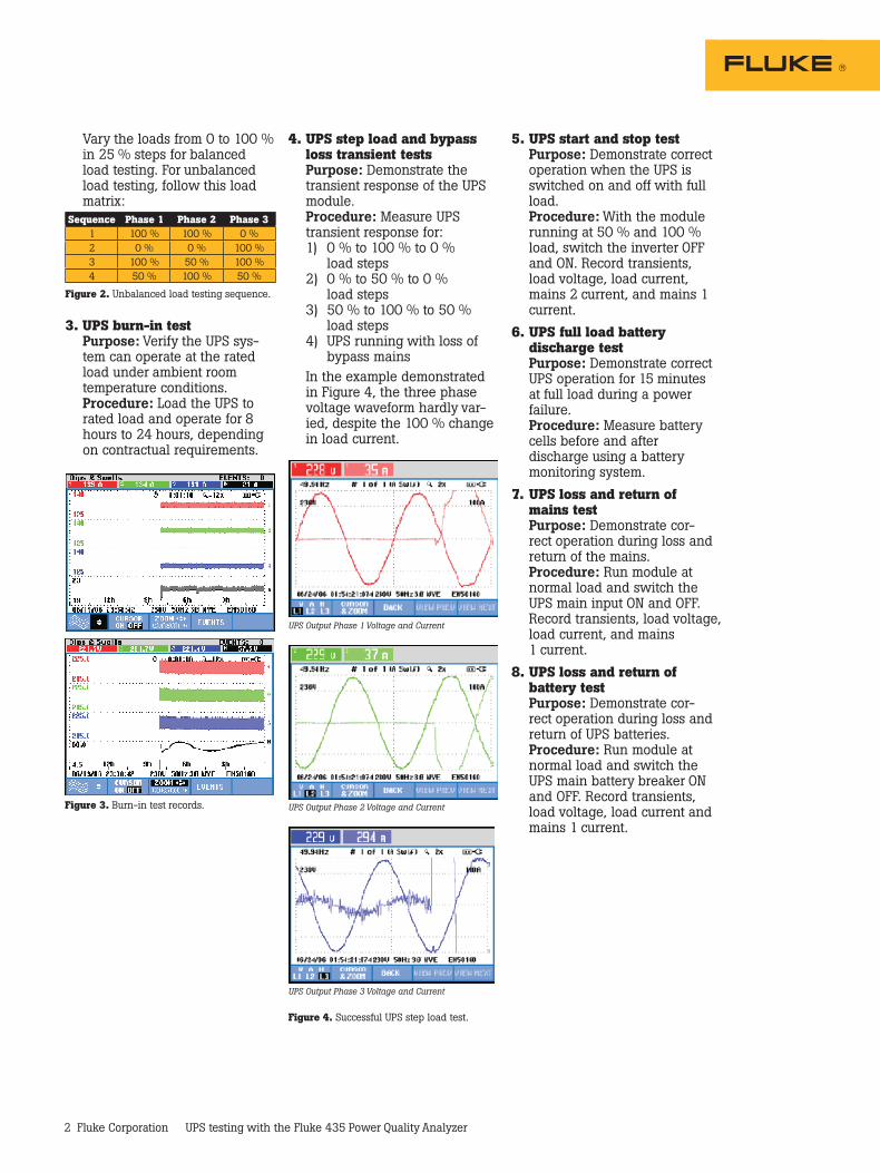
In the example demonstrated in Figure 4, the three phase voltage waveform hardly var-ied, despite the 100 % change in load current.
5. UPS start and stop test Purpose: Demonstrate correct
operation when the UPS is switched on and off with full load.
Procedure: With the module running at 50 % and 100 % load, switch the inverter OFF and ON. Record transients, load voltage, load current, mains 2 current, and mains 1 current.
6. UPS full load battery discharge test
Purpose: Demonstrate correct UPS operation for 15 minutes at full load during a power failure.
Procedure: Measure battery cells before and after discharge using a battery monitoring system.
7. UPS loss and return of mains test
Purpose: Demonstrate cor-rect operation during loss and return of the mains.
Procedure: Run module at normal load and switch the UPS main input ON and OFF.
Record transients, load voltage, load current, and mains 1 current.
8. UPS loss and return of battery test
Purpose: Demonstrate cor-rect operation during loss and return of UPS batteries.
Procedure: Run module at normal load and switch the UPS main battery breaker ON and OFF. Record transients, load voltage, load current and mains 1 current.
Figure 3. Burn-in test records.
UPS Output Phase 3 Voltage and Current
UPS Output Phase 2 Voltage and Current
UPS Output Phase 1 Voltage and Current
Figure 4. Successful UPS step load test.
3. UPS burn-in test Purpose: Verify the UPS sys-
tem can operate at the rated load under ambient room temperature conditions.
Procedure: Load the UPS to rated load and operate for 8 hours to 24 hours, depending on contractual requirements.
Figure 2. Unbalanced load testing sequence.

3 Fluke Corporation UPS testing with the Fluke 435 Power Quality Analyzer
FlukeCorporation PO Box 9090, Everett, WA USA 98206
FlukeEuropeB.V. PO Box 1186, 5602 BD Eindhoven, The Netherlands
Formoreinformationcall: In the U.S.A. (800) 443-5853 or Fax (425) 446-5116 In Europe/M-East/Africa +31 (0) 40 2675 200 or Fax +31 (0) 40 2675 222 In Canada (800)-36-FLUKE or Fax (905) 890-6866 From other countries +1 (425) 446-5500 or Fax +1 (425) 446-5116 Web access: http://www.fluke.com
©2007 Fluke Corporation. All rights reserved. Specifications subject to change without notice. Printed in U.S.A. 4/2007 3023525 A-EN-N Rev A
Pub-ID: 11603-eng
Fluke. Keeping your world up and running.®
9. UPS load transfer test Purpose: Demonstrate correct
operation during load transfer. Procedure: Run module at
normal load and switch UPS OFF and ON until the load is on static bypass. This procedure is reversed from static bypass to UPS.
Record load voltage, load cur-rent and bypass current.
10. UPS transfer to bypass and back test
Purpose: Demonstrate cor-rect operation with external bypass.
Procedure: Transfer the load to external bypass and back to UPS. Record load voltage and load current.
Combined testConnect the critical loads and standby generator and repeat the same tests at 0 % and 100 % load conditions. Monitor transfer between the mains supply, UPS, and standby generator to ensure that transients and waveform distortion stays within acceptable limits.
Maintenance testConduct periodic (monthly) main-tenance tests throughout the life of the contingency supply system. Follow the combined test proce-dure for everything except the standby generator—it only needs to be tested once a year.
UPS Output Blue Phase Voltage and Bypass Current
UPS Output Yellow Phase Voltage and Bypass Current
UPS Output Red Phase Voltage and Bypass Current
Figure 5. Step load test.
ConclusionMany tests are involved when commissioning and maintaining a contingency supply system. Many parameters (three phase voltage and current, power, power factor, harmonics and transients) must be logged simultaneously over 8 hours to 24 hours and document-ed in report format. Use a power quality analyzer with data log-ging and reporting capabilities, such as the Fluke 435 used by the project team (responsible for site assessment and installation) and the service team (post-sales maintenance) in this example.
Fluke sincerely appreciates all of the contributions made to this application note by the manage-ment and staff of MGE Asia Pte Ltd, a leading world manufacturer of UPS systems. These are the typical tests performed by MGE during installations, commission-ing and maintenance.