Embed Size (px)
Citation preview
Reliable Communication in Massive MIMOwith Low-Precision Converters
Christoph Studer
vip.ece.cornell.edu

Smartphone traffic evolution needs technology revolution
Source: Ericsson, June 2017
vip.ece.cornell.edu
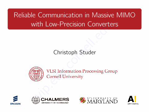
Fifth-generation (5G) may come to rescue
Source: Ericsson, June 2017
vip.ece.cornell.edu
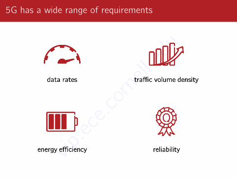
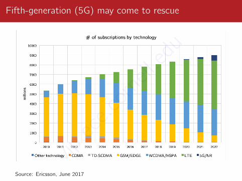
5G has a wide range of requirements
vip.ece.cornell.edu
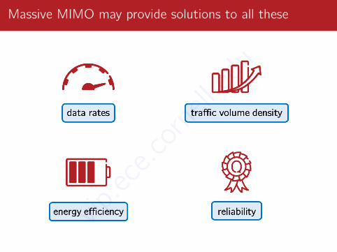
Massive MIMO may provide solutions to all these
vip.ece.cornell.edu
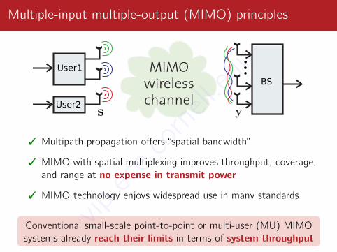
Multiple-input multiple-output (MIMO) principles
User1
User2
BS
3 Multipath propagation offers “spatial bandwidth”
3 MIMO with spatial multiplexing improves throughput, coverage,and range at no expense in transmit power
3 MIMO technology enjoys widespread use in many standards
Conventional small-scale point-to-point or multi-user (MU) MIMOsystems already reach their limits in terms of system throughput
vip.ece.cornell.edu
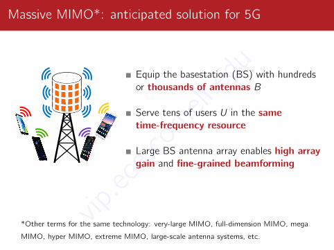
Massive MIMO*: anticipated solution for 5G
Equip the basestation (BS) with hundredsor thousands of antennas B
Serve tens of users U in the sametime-frequency resource
Large BS antenna array enables high arraygain and fine-grained beamforming
*Other terms for the same technology: very-large MIMO, full-dimension MIMO, mega
MIMO, hyper MIMO, extreme MIMO, large-scale antenna systems, etc.
vip.ece.cornell.edu
Promised gains of massive MIMO (in theory)
3 Improved spectral efficiency, coverage, and range
Ü 10× capacity increase over small-scale MIMO
Ü 100× increased radiated efficiency
3 Fading can be mitigated substantially → “channel hardening”
3 Significant cost and energy savings in analog RF circuitry
3 Robust to RF and hardware impairments
3 Simple baseband algorithms achieve optimal performancevip.ece.cornell.edu
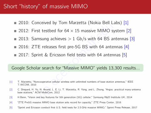
Short “history” of massive MIMO
2010: Conceived by Tom Marzetta (Nokia Bell Labs) [1]
2012: First testbed for 64× 15 massive MIMO system [2]
2013: Samsung achieves > 1 Gb/s with 64 BS antennas [3]
2016: ZTE releases first pre-5G BS with 64 antennas [4]
2017: Sprint & Ericsson field tests with 64 antennas [5]
Google Scholar search for “Massive MIMO” yields 13,300 results...
[1] T. Marzetta, “Noncooperative cellular wireless with unlimited numbers of base station antennas,” IEEET-WCOM, 2010
[2] C. Shepard, H. Yu, N. Anand, L. E. Li, T. Marzetta, R. Yang, and L. Zhong, “Argos: practical many-antennabase stations,” ACM MobiCom, 2012
[3] H.Benn, “Vision and key features for 5th generation (5G) cellular,” Samsung R&D Institute UK, 2014
[4] “ZTE Pre5G massive MIMO base station sets record for capacity,” ZTE Press Center, 2016
[5] “Sprint and Ericsson conduct first U.S. field tests for 2.5 GHz massive MIMO,” Sprint Press Release, 2017
vip.ece.cornell.edu

Practical challenges
vip.ece.cornell.edu
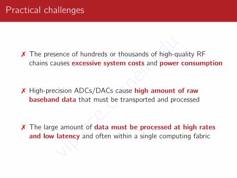
Practical challenges
7 The presence of hundreds or thousands of high-quality RFchains causes excessive system costs and power consumption
7 High-precision ADCs/DACs cause high amount of rawbaseband data that must be transported and processed
7 The large amount of data must be processed at high ratesand low latency and often within a single computing fabric
vip.ece.cornell.edu
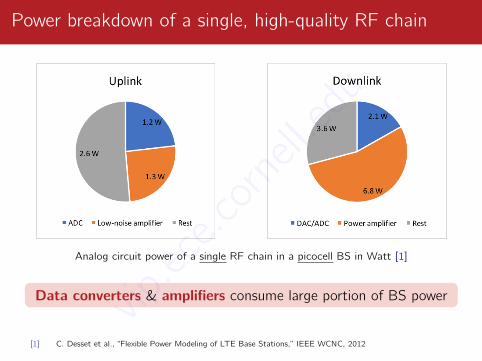
Power breakdown of a single, high-quality RF chain
Analog circuit power of a single RF chain in a picocell BS in Watt [1]
Data converters & amplifiers consume large portion of BS power
[1] C. Desset et al., “Flexible Power Modeling of LTE Base Stations,” IEEE WCNC, 2012
vip.ece.cornell.edu
We will show that massive MIMO enables reliablecommunication with low-precision data converters
vip.ece.cornell.edu
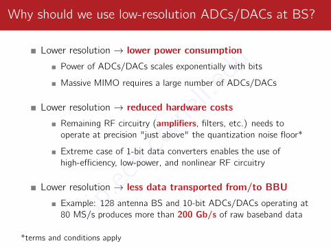
Why should we use low-resolution ADCs/DACs at BS?
Lower resolution → lower power consumptionPower of ADCs/DACs scales exponentially with bits
Massive MIMO requires a large number of ADCs/DACs
Lower resolution → reduced hardware costsRemaining RF circuitry (amplifiers, filters, etc.) needs tooperate at precision "just above" the quantization noise floor*
Extreme case of 1-bit data converters enables the use ofhigh-efficiency, low-power, and nonlinear RF circuitry
Lower resolution → less data transported from/to BBUExample: 128 antenna BS and 10-bit ADCs/DACs operating at80 MS/s produces more than 200 Gb/s of raw baseband data
*terms and conditions apply
vip.ece.cornell.edu
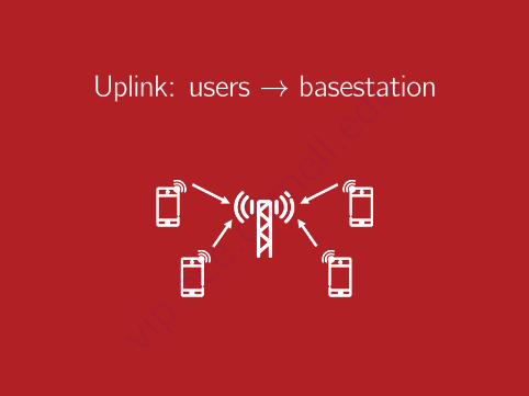
Uplink: users → basestation
vip.ece.cornell.edu
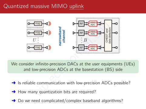
Quantized massive MIMO uplink
narr
ow
ban
d
ch
an
nel
. . .
RF
RF
RF
ADCADC
ADCADC
ADCADC
. . .
map.
map.
map.
CH
ES
T a
nd
data
dete
ctio
n
We consider infinite-precision DACs at the user equipments (UEs)and low-precision ADCs at the basestation (BS) side
Ü Is reliable communication with low-precision ADCs possible?
Ü How many quantization bits are required?
Ü Do we need complicated/complex baseband algorithms?vip.ece.cornell.edu
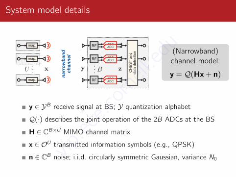
System model details
na
rro
wb
an
d
ch
an
ne
l. . .
RF
RF
RF
ADCADC
ADCADC
ADCADC
. . .
map.
map.
map.
CH
ES
T a
nd
da
ta d
ete
ctio
n (Narrowband)channel model:
y = Q(Hx+ n)
y ∈ YB receive signal at BS; Y quantization alphabet
Q(·) describes the joint operation of the 2B ADCs at the BS
H ∈ CB×U MIMO channel matrix
x ∈ OU transmitted information symbols (e.g., QPSK)
n ∈ CB noise; i.i.d. circularly symmetric Gaussian, variance N0vip.ece.cornell.edu
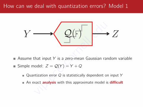
How can we deal with quantization errors? Model 1
Assume that input Y is a zero-mean Gaussian random variable
Simple model: Z = Q(Y ) = Y +Q
Quantization error Q is statistically dependent on input Y
An exact analysis with this approximate model is difficult
[1] A. Zymnis, S. Boyd, and E. Candès, “Compressed sensing with quantized measurements,” IEEE SP-L, 2010
[2] J. J. Bussgang, “Crosscorrelation functions of amplitude-distorted Gaussian signals,” MIT Research Laboratoryof Electronics, technical report, 1952
vip.ece.cornell.edu
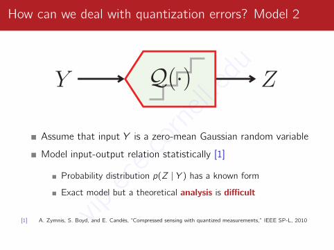
How can we deal with quantization errors? Model 2
Assume that input Y is a zero-mean Gaussian random variable
Model input-output relation statistically [1]
Probability distribution p(Z | Y ) has a known form
Exact model but a theoretical analysis is difficult
[1] A. Zymnis, S. Boyd, and E. Candès, “Compressed sensing with quantized measurements,” IEEE SP-L, 2010
[2] J. J. Bussgang, “Crosscorrelation functions of amplitude-distorted Gaussian signals,” MIT Research Laboratoryof Electronics, technical report, 1952
vip.ece.cornell.edu
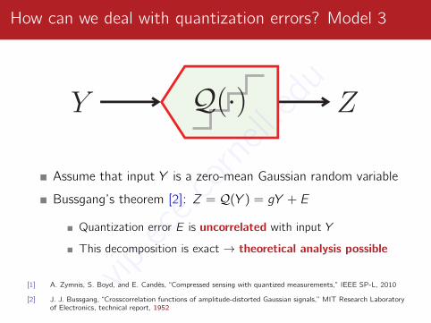
How can we deal with quantization errors? Model 3
Assume that input Y is a zero-mean Gaussian random variable
Bussgang’s theorem [2]: Z = Q(Y ) = gY + E
Quantization error E is uncorrelated with input Y
This decomposition is exact → theoretical analysis possible
[1] A. Zymnis, S. Boyd, and E. Candès, “Compressed sensing with quantized measurements,” IEEE SP-L, 2010
[2] J. J. Bussgang, “Crosscorrelation functions of amplitude-distorted Gaussian signals,” MIT Research Laboratoryof Electronics, technical report, 1952
vip.ece.cornell.edu
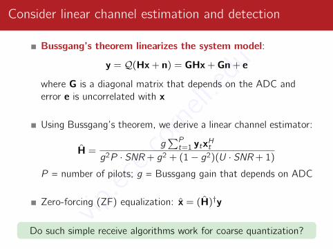
Consider linear channel estimation and detection
Bussgang’s theorem linearizes the system model:
y = Q(Hx+ n) = GHx+ Gn+ e
where G is a diagonal matrix that depends on the ADC anderror e is uncorrelated with x
Using Bussgang’s theorem, we derive a linear channel estimator:
H =g∑Pt=1 ytx
Ht
g2P · SNR + g2 + (1− g2)(U · SNR + 1)
P = number of pilots; g = Bussgang gain that depends on ADC
Zero-forcing (ZF) equalization: x = (H)†y
Do such simple receive algorithms work for coarse quantization?vip.ece.cornell.edu
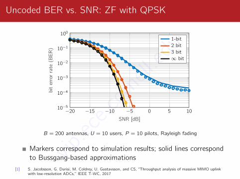
Uncoded BER vs. SNR: ZF with QPSK
−20 −15 −10 −5 0 5 1010−5
10−4
10−3
10−2
10−1
100
SNR [dB]
bit
erro
rra
te(B
ER
)
1-bit2 bit3 bit∞ bit
B = 200 antennas, U = 10 users, P = 10 pilots, Rayleigh fading
Markers correspond to simulation results; solid lines correspondto Bussgang-based approximations
[1] S. Jacobsson, G. Durisi, M. Coldrey, U. Gustavsson, and CS, “Throughput analysis of massive MIMO uplinkwith low-resolution ADCs,” IEEE T-WC, 2017
vip.ece.cornell.edu
Are these results still valid for realisticwideband massive MIMO-OFDM systems?
vip.ece.cornell.edu
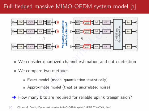
Full-fledged massive MIMO-OFDM system model [1]
FEC
freq
uen
cy-s
ele
cti
ve
wir
ele
ss c
han
nel
. . .
RF
RF
RF
. . .
S/P
S/P
S/P
. . .
DFT
DFT
DFT
. . .
CH
ES
T a
nd
data
dete
ctio
n
dec.
. . .
IDFT
IDFT
IDFT
. . .
P/S
P/S
P/S
. . .
RF
RF
RF
. . .
dec.
dec.
FEC
FEC
. . .
ADCADC
ADCADC
ADCADC
We consider quantized channel estimation and data detection
We compare two methods:
Exact model (model quantization statistically)
Approximate model (treat as unorrelated noise)
Ü How many bits are required for reliable uplink transmission?
[1] CS and G. Durisi, “Quantized massive MIMO-OFDM uplink,” IEEE T-WCOM, 2016
vip.ece.cornell.edu
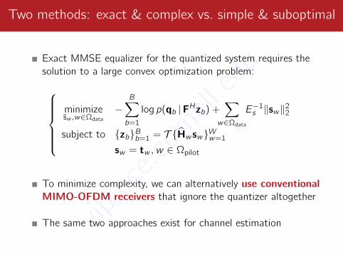
Two methods: exact & complex vs. simple & suboptimal
Exact MMSE equalizer for the quantized system requires thesolution to a large convex optimization problem:
minimizesw ,w∈Ωdata
−B∑b=1
log p(qb |FHzb) +∑
w∈Ωdata
E−1s ‖sw‖2
2
subject to zbBb=1 = T Hw swWw=1
sw = tw , w ∈ Ωpilot
To minimize complexity, we can alternatively use conventionalMIMO-OFDM receivers that ignore the quantizer altogether
The same two approaches exist for channel estimationvip.ece.cornell.edu
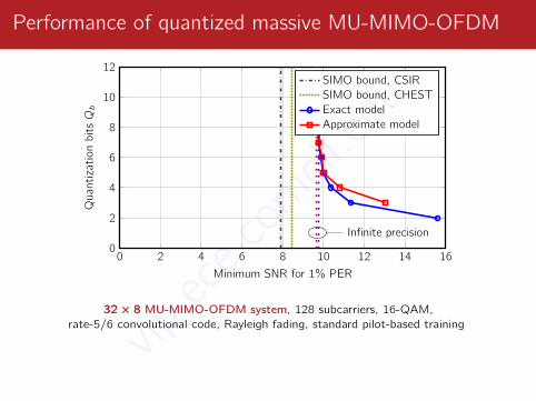
Performance of quantized massive MU-MIMO-OFDM
0 2 4 6 8 10 12 14 160
2
4
6
8
10
12
Infinite precision
Minimum SNR for 1% PER
QuantizationbitsQb
SIMO bound, CSIRSIMO bound, CHESTExact modelApproximate model
333222××× 888 MU-MIMO-OFDM system, 128 subcarriers, 16-QAM,rate-5/6 convolutional code, Rayleigh fading, standard pilot-based training
We can use traditional MIMO-OFDM receivers with 4-6 bit ADCs
vip.ece.cornell.edu
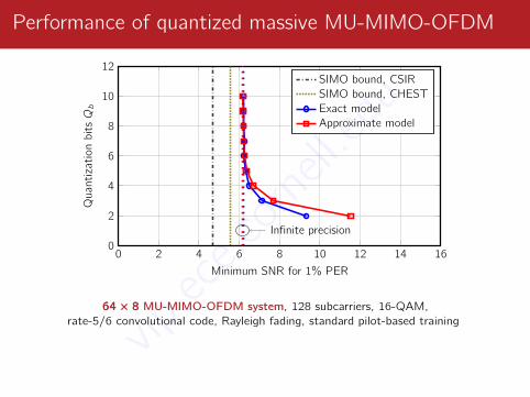
Performance of quantized massive MU-MIMO-OFDM
0 2 4 6 8 10 12 14 160
2
4
6
8
10
12
Infinite precision
Minimum SNR for 1% PER
QuantizationbitsQb
SIMO bound, CSIRSIMO bound, CHESTExact modelApproximate model
666444××× 888 MU-MIMO-OFDM system, 128 subcarriers, 16-QAM,rate-5/6 convolutional code, Rayleigh fading, standard pilot-based training
We can use traditional MIMO-OFDM receivers with 4-6 bit ADCs
vip.ece.cornell.edu
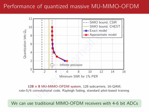
Performance of quantized massive MU-MIMO-OFDM
0 2 4 6 8 10 12 14 160
2
4
6
8
10
12
Infinite precision
Minimum SNR for 1% PER
QuantizationbitsQb
SIMO bound, CSIRSIMO bound, CHESTExact modelApproximate model
111222888××× 888 MU-MIMO-OFDM system, 128 subcarriers, 16-QAM,rate-5/6 convolutional code, Rayleigh fading, standard pilot-based training
We can use traditional MIMO-OFDM receivers with 4-6 bit ADCsvip.ece.cornell.edu
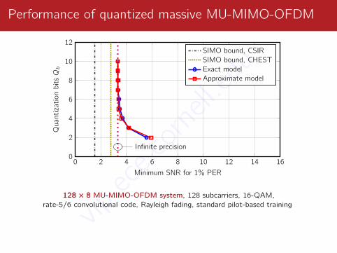
Performance of quantized massive MU-MIMO-OFDM
0 2 4 6 8 10 12 14 160
2
4
6
8
10
12
Infinite precision
Minimum SNR for 1% PER
QuantizationbitsQb
SIMO bound, CSIRSIMO bound, CHESTExact modelApproximate model
111222888××× 888 MU-MIMO-OFDM system, 128 subcarriers, 16-QAM,rate-5/6 convolutional code, Rayleigh fading, standard pilot-based training
We can use traditional MIMO-OFDM receivers with 4-6 bit ADCs
vip.ece.cornell.edu
Downlink: basestation → users
vip.ece.cornell.edu
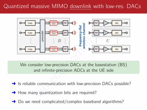
Quantized massive MIMO downlink with low-res. DACs
det.
freq
uen
cy-f
lat
wir
ele
ss c
han
nel
pre
cod
er
. .
.
DAC
. .
.
RFmap.
RF
RF
RF
RF
RF
DAC
DACDAC
DACDAC
. .
.
. .
.
. .
.
map.
map.
det.
det.
We consider low-precision DACs at the basestation (BS)and infinite-precision ADCs at the UE side
Ü Is reliable communication with low-precision DACs possible?
Ü How many quantization bits are required?
Ü Do we need complicated/complex baseband algorithms?vip.ece.cornell.edu
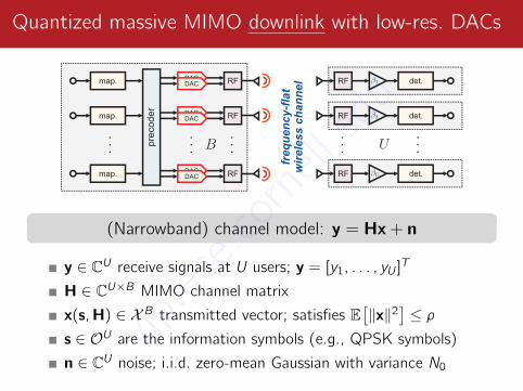
Quantized massive MIMO downlink with low-res. DACs
det.
freq
uen
cy-f
lat
wir
ele
ss c
han
nel
pre
cod
er
. .
.
DAC
. .
.
RFmap.
RF
RF
RF
RF
RF
DAC
DACDAC
DACDAC
. .
.
. .
.
. .
.
map.
map.
det.
det.
(Narrowband) channel model: y = Hx+ n
y ∈ CU receive signals at U users; y = [y1, . . . , yU ]T
H ∈ CU×B MIMO channel matrix
x(s,H) ∈ XB transmitted vector; satisfies E[‖x‖2
]≤ ρ
s ∈ OU are the information symbols (e.g., QPSK symbols)
n ∈ CU noise; i.i.d. zero-mean Gaussian with variance N0
vip.ece.cornell.edu
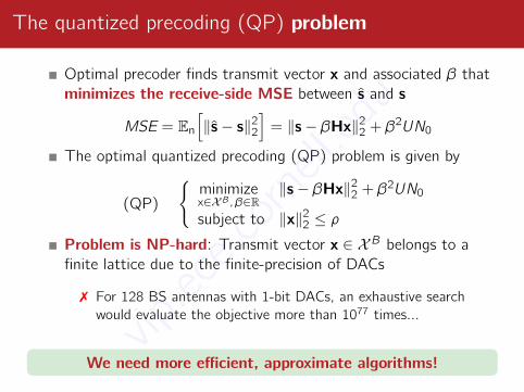
The quantized precoding (QP) problem
Optimal precoder finds transmit vector x and associated β thatminimizes the receive-side MSE between s and s
MSE = En
[‖s− s‖2
2
]= ‖s− βHx‖2
2 + β2UN0
The optimal quantized precoding (QP) problem is given by
(QP)
minimizex∈XB, β∈R
‖s− βHx‖22 + β2UN0
subject to ‖x‖22 ≤ ρ
Problem is NP-hard: Transmit vector x ∈ XB belongs to afinite lattice due to the finite-precision of DACs
7 For 128 BS antennas with 1-bit DACs, an exhaustive searchwould evaluate the objective more than 1077 times...
We need more efficient, approximate algorithms!vip.ece.cornell.edu
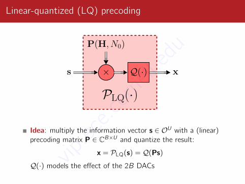
Linear-quantized (LQ) precoding
PLQ(·)×s
P(H, N0)
Q(·) x
Idea: multiply the information vector s ∈ OU with a (linear)precoding matrix P ∈ CB×U and quantize the result:
x = PLQ(s) = Q(Ps)
Q(·) models the effect of the 2B DACsvip.ece.cornell.edu
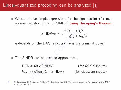
Linear-quantized precoding can be analyzed [1]
We can derive simple expressions for the signal-to-interference-noise-and-distortion ratio (SINDR) using Bussgang’s theorem:
SINDRZF ≈g2(B − U)/U
(1− g2) + N0/ρ
g depends on the DAC resolution; ρ is the transmit power
The SINDR can be used to approximate
BER ≈ Q(√SINDR) (for QPSK inputs)
Rsum ≈ U log2(1 + SINDR) (for Gaussian inputs)
[1] S. Jacobsson, G. Durisi, M. Coldrey, T. Goldstein, and CS, “Quantized precoding for massive MU-MIMO,"IEEE T-COM, 2017
vip.ece.cornell.edu
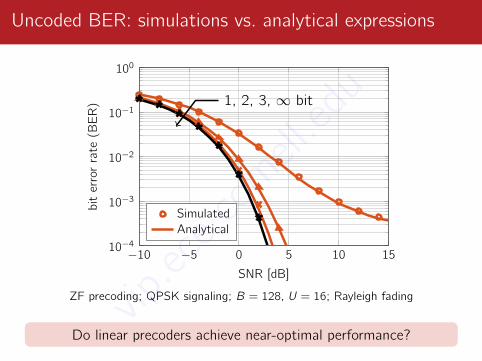
Uncoded BER: simulations vs. analytical expressions
−10 −5 0 5 10 1510−4
10−3
10−2
10−1
100
1, 2, 3, ∞ bit
SNR [dB]
bit
erro
rra
te(B
ER
)
SimulatedAnalytical
ZF precoding; QPSK signaling; B = 128, U = 16; Rayleigh fading
Do linear precoders achieve near-optimal performance?vip.ece.cornell.edu
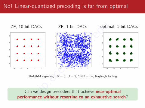
No! Linear-quantized precoding is far from optimal
ZF, 10-bit DACs
−4 −2 0 2 4
−4
−2
0
2
4
ZF, 1-bit DACs
−4 −2 0 2 4
−4
−2
0
2
4
optimal, 1-bit DACs
−4 −2 0 2 4
−4
−2
0
2
4
16-QAM signaling, B = 8, U = 2, SNR =∞; Rayleigh fading
Can we design precoders that achieve near-optimalperformance without resorting to an exhaustive search?vip
.ece.cornell.edu
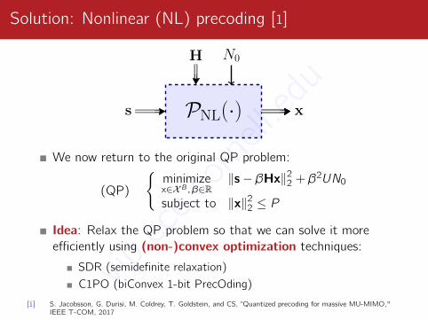
Solution: Nonlinear (NL) precoding [1]
PNL(·)s x
H N0
We now return to the original QP problem:
(QP)
minimizex∈XB, β∈R
‖s− βHx‖22 + β2UN0
subject to ‖x‖22 ≤ P
Idea: Relax the QP problem so that we can solve it moreefficiently using (non-)convex optimization techniques:
SDR (semidefinite relaxation)C1PO (biConvex 1-bit PrecOding)
[1] S. Jacobsson, G. Durisi, M. Coldrey, T. Goldstein, and CS, “Quantized precoding for massive MU-MIMO,"IEEE T-COM, 2017
vip.ece.cornell.edu
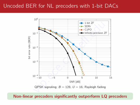
Uncoded BER for NL precoders with 1-bit DACs
−10 −5 0 5 10 1510−4
10−3
10−2
10−1
100
SNR [dB]
biterrorrate
(BER)
1-bit ZFSDRrC1POInfinite-precision ZF
QPSK signaling; B = 128, U = 16; Rayleigh fading
Non-linear precoders significantly outperform LQ precodersvip.ece.cornell.edu

“In theory, theory and practice are the same.In practice, they are not.” [A. Einstein]
vip.ece.cornell.edu
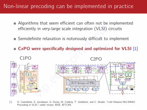
Non-linear precoding can be implemented in practice
Algorithms that seem efficient can often not be implementedefficiently in very-large scale integration (VLSI) circuits
Semidefinite relaxation is notoriously difficult to implement
CxPO were specifically designed and optimized for VLSI [1]
C1PO C2PO
[1] O. Castañeda, S. Jacobsson, G. Durisi, M. Coldrey, T. Goldstein, and C. Studer, “1-bit Massive MU-MIMOPrecoding in VLSI,” under review, IEEE JETCAS
vip.ece.cornell.edu
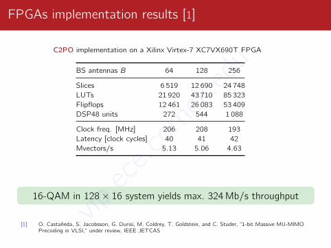
FPGAs implementation results [1]
C2PO implementation on a Xilinx Virtex-7 XC7VX690T FPGA
BS antennas B 64 128 256
Slices 6 519 12 690 24 748LUTs 21 920 43 710 85 323Flipflops 12 461 26 083 53 409DSP48 units 272 544 1 088
Clock freq. [MHz] 206 208 193Latency [clock cycles] 40 41 42Mvectors/s 5.13 5.06 4.63
16-QAM in 128× 16 system yields max. 324Mb/s throughput
[1] O. Castañeda, S. Jacobsson, G. Durisi, M. Coldrey, T. Goldstein, and C. Studer, “1-bit Massive MU-MIMOPrecoding in VLSI,” under review, IEEE JETCAS
vip.ece.cornell.edu
Are these results still valid forwideband massive MIMO-OFDM systems?
vip.ece.cornell.edu
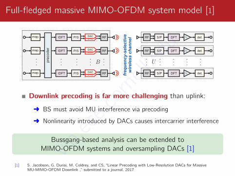
Full-fledged massive MIMO-OFDM system model [1]
det.
fre
qu
en
cy
-se
lec
tiv
ew
ire
les
s c
ha
nn
el
. .
.
RF
RF
RF
. .
.
. .
.
. .
.
DACP/S
P/S
P/S.
. .
IDFT
IDFT
IDFT
. .
.
pre
cod
er
map..
. .
DFT
DFT
DFT
. .
.
S/P
S/P
S/P
. .
.
RF
RF
RF
. .
.
map.
map.
det.
det.
DAC
DACDAC
DACDAC
Downlink precoding is far more challenging than uplink:
Ü BS must avoid MU interference via precoding
Ü Nonlinearity introduced by DACs causes intercarrier interference
Bussgang-based analysis can be extended toMIMO-OFDM systems and oversampling DACs [1]
[1] S. Jacobson, G. Durisi, M. Coldrey, and CS, “Linear Precoding with Low-Resolution DACs for MassiveMU-MIMO-OFDM Downlink ,” submitted to a journal, 2017
vip.ece.cornell.edu
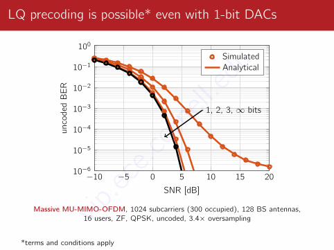
LQ precoding is possible* even with 1-bit DACs
−10 −5 0 5 10 15 2010−6
10−5
10−4
10−3
10−2
10−1
100
1, 2, 3, ∞ bits
SNR [dB]
unco
ded
BER
SimulatedAnalytical
Massive MU-MIMO-OFDM, 1024 subcarriers (300 occupied), 128 BS antennas,16 users, ZF, QPSK, uncoded, 3.4× oversampling
*terms and conditions apply
vip.ece.cornell.edu
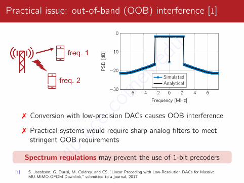
Practical issue: out-of-band (OOB) interference [1]
−6 −4 −2 0 2 4 6−30
−20
−10
0
Frequency [MHz]PSD
[dB
]
SimulatedAnalytical
7 Conversion with low-precision DACs causes OOB interference
7 Practical systems would require sharp analog filters to meetstringent OOB requirements
Spectrum regulations may prevent the use of 1-bit precoders
[1] S. Jacobson, G. Durisi, M. Coldrey, and CS, “Linear Precoding with Low-Resolution DACs for MassiveMU-MIMO-OFDM Downlink,” submitted to a journal, 2017
vip.ece.cornell.edu
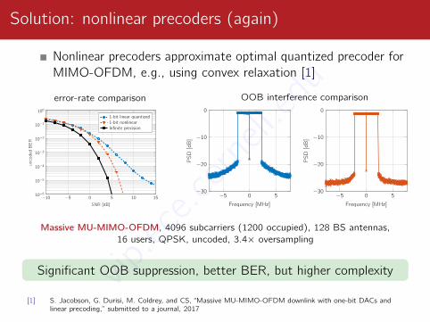
Solution: nonlinear precoders (again)
Nonlinear precoders approximate optimal quantized precoder forMIMO-OFDM, e.g., using convex relaxation [1]
error-rate comparison
−10 −5 0 5 10 1510−6
10−5
10−4
10−3
10−2
10−1
100
SNR [dB]
uncodedBER
1-bit linear quantized1-bit nonlinearInfinite precision
OOB interference comparison
−5 0 5−30
−20
−10
0
Frequency [MHz]
PSD
[dB
]−5 0 5
−30
−20
−10
0
Frequency [MHz]
PSD
[dB
]
Massive MU-MIMO-OFDM, 4096 subcarriers (1200 occupied), 128 BS antennas,16 users, QPSK, uncoded, 3.4× oversampling
Significant OOB suppression, better BER, but higher complexity
[1] S. Jacobson, G. Durisi, M. Coldrey, and CS, “Massive MU-MIMO-OFDM downlink with one-bit DACs andlinear precoding,” submitted to a journal, 2017
vip.ece.cornell.edu

Conclusions and open problems
vip.ece.cornell.edu
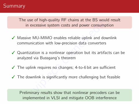
Summary
The use of high-quality RF chains at the BS would resultin excessive system costs and power consumption
3 Massive MU-MIMO enables reliable uplink and downlinkcommunication with low-precision data converters
3 Quantization is a nonlinear operation but its artifacts can beanalyzed via Bussgang’s theorem
3 The uplink requires no changes; 4-to-6 bit are sufficient
3 The downlink is significantly more challenging but feasible
Preliminary results show that nonlinear precoders can beimplemented in VLSI and mitigate OOB interference
vip.ece.cornell.edu
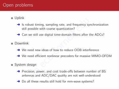
Open problems
Uplink
Ü Is robust timing, sampling rate, and frequency synchronizationstill possible with coarse quantization?
Ü Can we still use digital time-domain filters after the ADCs?
Downlink
Ü We need new ideas of how to reduce OOB interference
Ü We need efficient nonlinear precoders for massive MIMO-OFDM
System design
Ü Precision, power, and cost trade-offs between number of BSantennas and ADC/DAC quality are not well-understood
Ü Do all these results still hold for mm-wave systems?vip.ece.cornell.edu

Thanks to my collaborators!
More information → vip.ece.cornell.eduvip.ece.cornell.edu