Embed Size (px)
Citation preview
Reliance Industries, LLC
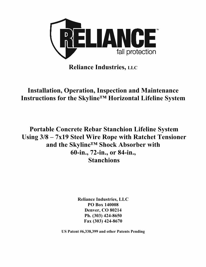
Installation, Operation, Inspection and Maintenance Instructions for the Skyline™ Horizontal Lifeline System
Portable Concrete Rebar Stanchion Lifeline System Using 3/8 – 7x19 Steel Wire Rope with Ratchet Tensioner
and the Skyline™ Shock Absorber with 60-in., 72-in., or 84-in.,
Stanchions
Reliance Industries, LLC PO Box 140008
Denver, CO 80214 Ph. (303) 424-8650 Fax (303) 424-8670
US Patent #6,338,399 and other Patents Pending
User Instructions 6370 Skyline Portable Concrete HLL System Reliance Industries, LLC
Reliance Industries, LLC Denver, CO 80214 Ph. (800) 488-5751 Fax (303) 424-8670
Rev: - Date: 05/01/03 Doc.: M-6370 Page 2 of 19
Important Instructions! These instructions must be kept on file and available for the users reference at all times. The users must read and full understand these instructions or have the instructions explained in detail before using this equipment. Failure to observe these instructions could result in serious injury or death. Prior to use, all workers must be trained in the proper use of all systems and equipment. A Training and Instruction review should be repeated at regular intervals. A rescue plan must be prepared; the workers must be trained in its use, and rescue equipment must be on hand prior to any use of this horizontal lifeline system. This system is to be used only with a Grade 40 or Grade 60 rebar of #6 through #11 sizes (3/4” – 1-1/2”). Rebar under #6 size WILL NOT be gripped adequately by the clamp. The clamps of the Rebar Stanchion tieback cables are NOT to be used with other grades of rebar. Any questions regarding these instructions should be directed to: Reliance Industries, LLC PO Box 140008 Denver, CO 80214 Ph. (303) 424-8650 Fax (303) 424-8670
User Instructions 6370 Skyline Portable Concrete HLL System Reliance Industries, LLC
Reliance Industries, LLC Denver, CO 80214 Ph. (800) 488-5751 Fax (303) 424-8670
Rev: - Date: 05/01/03 Doc.: M-6370 Page 3 of 19
Table of Contents IMPORTANT INSTRUCTIONS! ............................................................................................................................................... 2
SYSTEM DESCRIPTION............................................................................................................................................................ 5
ANCHORAGE POINTS............................................................................................................................................................... 6
HORIZONTAL LIFELINE SYSTEM COMPONENTS .......................................................................................................... 6
PERSONAL FALL ARREST EQUIPMENT USED WITH HORIZONTAL LIFELINES.................................................. 8
INSTALLATION LAYOUT CONSIDERATIONS................................................................................................................... 8
INSTALLATION .......................................................................................................................................................................... 8
EXAMPLE -COMPUTER GENERATED SYSTEM PARAMETER DOCUMENT....................................................................................... 9 CHART 1. STANCHION HEIGHT VS. TIE BACK SPACING ................................................................................................................ 9
INSTALLATION OF REBAR INTO COLUMN TOPS ......................................................................................................... 11
HLL INSTALLATION PROCEDURES .................................................................................................................................. 12
TRAINING................................................................................................................................................................................... 15
PLANNING FOR RESCUE ....................................................................................................................................................... 16
INSPECTION .............................................................................................................................................................................. 16
SERVICING ................................................................................................................................................................................ 16
WARNINGS AND LIMITATIONS .......................................................................................................................................... 17
INSPECTION LOG FOR HLL SYSTEMS.............................................................................................................................. 18
SKYLINE™ HORIZONTAL LIFELINE DIAGRAM ........................................................................................................... 19
User Instructions 6370 Skyline Portable Concrete HLL System Reliance Industries, LLC
Reliance Industries, LLC Denver, CO 80214 Ph. (800) 488-5751 Fax (303) 424-8670
Rev: - Date: 05/01/03 Doc.: M-6370 Page 4 of 19
Important OSHA Regulations Covering the Use of Horizontal Lifeline Systems OSHA 1910.66 Subpart M – 1926.502 (d)(8):
Horizontal Lifelines shall be designed, installed, and used under the supervision of a qualified person as part of a complete fall arrest system, which maintains a safety factor of at least two.
OSHA 1910.66 (b):
“Qualified Person” means one with a recognized degree or professional certificate and extensive knowledge and experience in the subject field who is capable of design, analysis, evaluation, and specifications in the subject work, project, or product.
OSHA 1910.66 (b): “Competent Person” means a person who is capable of identifying hazardous or dangerous conditions in the personal fall arrest system or any component thereof, as well as in their application and use with related equipment
OSHA 1910.66: Personal fall arrest systems shall be rigged such that an employee can neither free-fall more than 6-ft. nor contact any lower surface.
OSHA 1910.66 (n): The sag in the lifeline should be minimized to prevent the connecting piece of equipment (self-retracting lanyard or other appropriate personal fall arrest device) from sliding down the lifeline to a position which creates a swing hazard during a fall arrest.
OSHA Standards, Interpretations and Compliance Letters, 02/09/1995-Criteria for personal fall arrest systems:
The free-fall distance is limited to 6 feet. The deceleration distance must not exceed 42 inches; lifeline elongation is not included in deceleration distance; and the total fall distance is unregulated except that the employee cannot make contact with a lower level…The safety factor of two should be applied based on the anticipated maximum arrest force, not the fall energy.
User Instructions 6370 Skyline Portable Concrete HLL System Reliance Industries, LLC
Reliance Industries, LLC Denver, CO 80214 Ph. (800) 488-5751 Fax (303) 424-8670
Rev: - Date: 05/01/03 Doc.: M-6370 Page 5 of 19
System Description The Skyline™ Horizontal Lifeline System #6370 is designed for use as a portable horizontal lifeline system. It is constructed exclusively of 3/8 – 7x19 wire rope that is available in both carbon steel (IPS) and stainless steel. It is designed to enable the user to attach to end anchorages or erected tubular steel stanchions in work areas where no overhead anchor points exist. Its unique design allows the system to be set-up as a standard horizontal lifeline (a “straight run”) system, or, by adding a second tie back head at a 90-degree angle to the first. It can be arranged as an “L” or quad system. With a quad system it is possible to run a perimeter horizontal lifeline system around a square work area with a minimum amount of additionally required equipment. The system, in general, is designed for use by up to 4 persons at the same time, and can span distances up to 200 ft. However, span length and number of persons on the system determine input energy (and therefore, final line tension) and not all combinations of span lengths and number of workers are possible. The user must consult the manufacturer for exact system parameters for each installation, or in the event that the system is moved. System parameters are provided in the form of computer generated anticipated line tension and Minimum Required Clearance (MRC) data that is traceable to actual test results for each system installation. The computer generated designs are prepared from verifiable test data and include a 2 ft. safety factor for Minimum Required Clearance, and a 2 to 1 Safety Factor over the minimum cable breaking strength for maximum allowable line tension. This system design is predicated on the use of a full-body harness for the worker, double-action, single-locking snap hooks to attach to the lifeline, and a shock absorbing vertical lifeline or self-retracting lanyard (SRL) with 900 lb. maximum arrest force. Non-shock absorbing lanyards and retractables that do not have “slip-clutch” type internal 900 lb. MAF shock absorbers are NOT allowed for use as vertical lifelines on this system. Any attachment to the horizontal lifeline must transfer fall arrest forces to the body through the dorsal d-ring of the full body harness only. Harness side and chest d-rings are not allowable lanyard connection points. All Skyline™ HLL systems are supplied with an integral shock absorber in the line and no system may be used without one. The four main functions of the shock absorber are:
1. It adds energy capacity to the system to increase the safety of short horizontal lifelines. 2. It creates mechanical hysterisis (friction) in the system to absorb rebound energy. 3. It decreases low sag angle amplification by controllably elongating the horizontal lifeline during
a fall. 4. It allows the cable to be tuned (or pre-loaded to a higher initial line tension) to force the cable to
absorb energy at a higher rate.
User Instructions 6370 Skyline Portable Concrete HLL System Reliance Industries, LLC
Reliance Industries, LLC Denver, CO 80214 Ph. (800) 488-5751 Fax (303) 424-8670
Rev: - Date: 05/01/03 Doc.: M-6370 Page 6 of 19
The shock absorber has a built in spring-loaded tensioner that indicates when the proper pre-tension has been achieved. Normally the pre-tension is set at 1000-lb. but may be changed for specifically designed applications. When a system is installed, the pre-tension must be set according to the installation instructions. Not all systems are perfectly rigid; therefore, pre-tension may change over time. Prior to each use, the worker must check the pre-tension of the system and adjust it accordingly. When the pre-tension of a system is closely controlled, the fall distance and final line tension are easily predictable. Knowing that the pre-tension of a horizontal lifeline is set correctly is of utmost importance to the predictability and safety of the system.
Anchorage Points The strength of horizontal lifeline anchorage points must be at least two times the anticipated line tension. This strength must be certified by a qualified person and must be verifiable be either calculation or testing. Anchorage connectors must be selected carefully. Eyebolts should not be used if they will be loaded at an angle to their axis, unless the loads fall within design parameters for such use. Weld-on lugs should not be less than ½ inch in width and should not be made of steel with less than 50,000-PSI yield strength. The proper stress areas and weld areas must be calculated to assure proper safety. If in question, consult Reliance Industries engineering staff for proper design requirements.
Horizontal Lifeline System Components The System #6370 Skyline™ Horizontal Lifeline system consists of the following standard approved and compatible components: • 1 ea. Model 6000 Skyline™ Shock Absorber (stainless steel) • 1 ea. Model 6050 Steel In-Line Cable Clamp (zinc plated carbon steel) • 4 ea. Model 6062 ½” bow shackles (stainless steel) • 1 ea. Model 6090 3” Ratchet Assembly • 1 ea. Model 6092 10’ Ratchet Strap • 2 ea. Model 84”-6220, or 72”-6210, or 60”-6200, Stanchion Load Tube. • 1 ea. Model 6070 Galvanized 3/8”- 7 x 19 wire rope assembly
Where corrosion may be a concern, the following option is available as a replacement for the galvanized wire rope and cable clamp: • 1 ea. Model 6072 Stainless steel 3/8” – 7x19 wire rope assembly • 1 ea. Model 6052 Stainless steel In-Line Cable Clamp Due to workplace configurations, bypass anchorages or stanchions may also be necessary. Please contact Reliance Industries Engineering for help with the selection of the correct stanchion for your application.
User Instructions 6370 Skyline Portable Concrete HLL System Reliance Industries, LLC
Reliance Industries, LLC Denver, CO 80214 Ph. (800) 488-5751 Fax (303) 424-8670
Rev: - Date: 05/01/03 Doc.: M-6370 Page 7 of 19
To take advantage of the unique design of the stanchion and head assemblies and arrange the system into a perimeter horizontal lifeline system or to run a second lifeline at 90 degrees to the first, additional equipment would be required. To create an “L” shaped system, in addition to the equipment of the #6370 System listed above, one would need the following: • 1 ea. Model 84”-6220, or 72”-6210, or 60”-6200, Stanchion Load Tube • 1 ea. Model #6310 Skyline™ Horizontal Lifeline System • 1 ea. Model 84”-6220-21, or 72”-6210-21, or 60”-6200-21, Rebar Anchor Stanchion Head Assembly. To create an “U” shaped system, in addition to the equipment of the #6370 System listed above, one would need the following: • 1 ea. Model #6370 System (a total of 2 complete #6370 Systems are required). • 1 ea. Model #6310 Skyline™ Horizontal Lifeline System • 2 ea. Model 84”-6220-21, or 72”-6210-21, or 60”-6200-21, Rebar Anchor Stanchion Head Assembly. To create a box shaped system or form a perimeter horizontal lifeline system, in addition to the equipment of the #6370 System listed above, one would need the following: • 1 ea. Model #6370 System (a total of 2 complete #6370 Systems are required). • 2 ea. Model #6310 Skyline™ Horizontal Lifeline System • 4 ea. Model 84”-6220-21, or 72”-6210-21, or 60”-6200-21, Rebar Anchor Stanchion Head Assembly. The above systems may also be used with (or require) the Clamp-on Bypass for Rebar, Model #6166. The Clamp-on Bypass Bracket is an intermediate support bracket for use with Skyline™ Horizontal Lifeline Systems to provide support for long span lifelines by attaching to rebar through the use of the same handknob system as the tie-back cables. The actual selection of components and options for the design of a horizontal lifeline system should only be performed by a Reliance Industries Qualified Person, or a state registered Professional Engineer who is experienced in the design and use of safety systems. The Skyline™ Horizontal Lifeline system is designed for use with the approved, above listed compatible components only. Substitutions or replacements with non-approved components may endanger the system integrity and may affect the safety and reliability of the total system. Please consult with Reliance Industries Engineering concerning questions about equipment, replacements, or substitutions. This system is to be used only with a Grade 40 or Grade 60 rebar of #6 through #11 sizes (3/4” – 1-1/2”). Rebar under #6 size WILL NOT be gripped adequately by the clamp. The clamps of the Rebar Stanchion tieback cables are NOT to be used with other grades of rebar.
User Instructions 6370 Skyline Portable Concrete HLL System Reliance Industries, LLC
Reliance Industries, LLC Denver, CO 80214 Ph. (800) 488-5751 Fax (303) 424-8670
Rev: - Date: 05/01/03 Doc.: M-6370 Page 8 of 19
Personal Fall Arrest Equipment Used with Horizontal Lifelines It is of utmost importance in the design of horizontal lifelines to be able to predict the vertical fall arrest forces that will be imposed on a lifeline during a fall. Normally the lifeline will elongate under increasing tension until the horizontal lifeline imposes a 900-lbf. Vertical force on the shock absorbing lanyard and then the lanyard will begin to rip out (or extend in the case of a SRL) until all of the fall energy has been absorbed. For multiple persons this force increases as a multiple of 900-lbs. The shock-absorbing lanyard, therefore, is vital in predicting and limiting horizontal lifeline tension. Only shock absorbing lanyards (or SRLs) with 900 lb. maximum arrest force are allowed for use with this system. Care should also be used in selecting harnesses for use with horizontal lifeline systems. Due to the HLL sag height, additional distance required for clearance when using horizontal lifeline systems is often the limiting factor in determining whether a HLL system can be used for a particular application. Harnesses with sewn down back pads can limit as much as 1 ft. of back pad slippage during fall arrest, giving additional clearance for safety. If the system will be used where a worker could encounter a head first free-fall, a non-secured back pad can slide down the webbing to the small of the back, allowing the worker to fall out of the harness through the top by allowing the harness straps to slip over the shoulders. For this reason, we recommend the use of a full body, crossover or pullover type harness with sewn down or slip resistant back pads for all installations.
Installation Layout Considerations Most HLL installations consist of either single-span or multi-span systems. Single-span systems consist of two end anchorages with a single HLL lifeline attached between them. Multi-span systems consist of two end anchorages and multiple intermediate (bypass) supports through which the cable passes, but to which it is not attached. Normally the bypasses consist of a structure that will allow a lanyard snap to pass through without allowing the cable to become disconnected. Input energy into an HLL system during fall arrest is usually determined by span length. The longer the span, the farther a person will fall during fall arrest and therefore, the greater the input energy. The more people that fall on a system at one time, the greater the falling weight and this also increases the input energy. In order to limit input energy into a system, one must limit the number of persons on a system and also limit the span length. On the other hand, the cable, having the greatest energy capacity (or ability to absorb energy) of all the components of a system due to its ability to strain under stress, must be long in order to absorb the greatest amount of energy. Therefore, the safest way to rig and assemble a horizontal lifeline system is to use the longest cable length possible with bypass supports located to reduce sub-span length to as short as possible. Only minimum required clearance limits (MRC) should be used to determine maximum allowable line length.
Installation
User Instructions 6370 Skyline Portable Concrete HLL System Reliance Industries, LLC
Reliance Industries, LLC Denver, CO 80214 Ph. (800) 488-5751 Fax (303) 424-8670
Rev: - Date: 05/01/03 Doc.: M-6370 Page 9 of 19
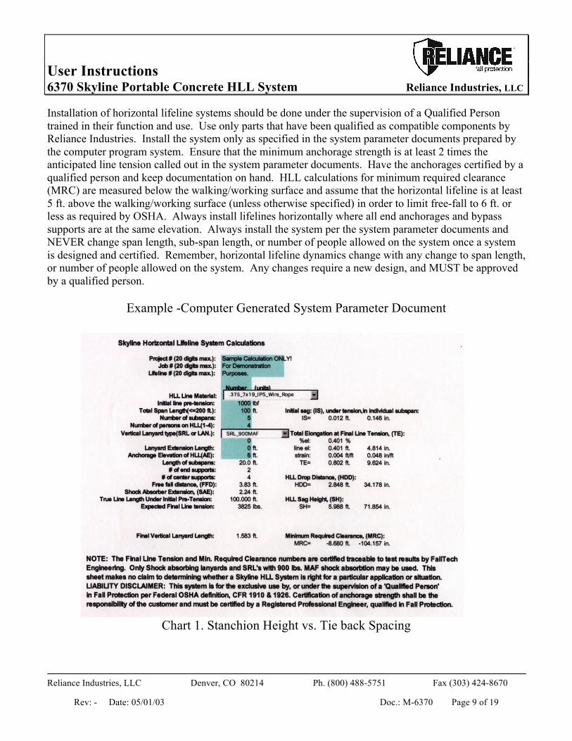
Installation of horizontal lifeline systems should be done under the supervision of a Qualified Person trained in their function and use. Use only parts that have been qualified as compatible components by Reliance Industries. Install the system only as specified in the system parameter documents prepared by the computer program system. Ensure that the minimum anchorage strength is at least 2 times the anticipated line tension called out in the system parameter documents. Have the anchorages certified by a qualified person and keep documentation on hand. HLL calculations for minimum required clearance (MRC) are measured below the walking/working surface and assume that the horizontal lifeline is at least 5 ft. above the walking/working surface (unless otherwise specified) in order to limit free-fall to 6 ft. or less as required by OSHA. Always install lifelines horizontally where all end anchorages and bypass supports are at the same elevation. Always install the system per the system parameter documents and NEVER change span length, sub-span length, or number of people allowed on the system once a system is designed and certified. Remember, horizontal lifeline dynamics change with any change to span length, or number of people allowed on the system. Any changes require a new design, and MUST be approved by a qualified person.
Example -Computer Generated System Parameter Document
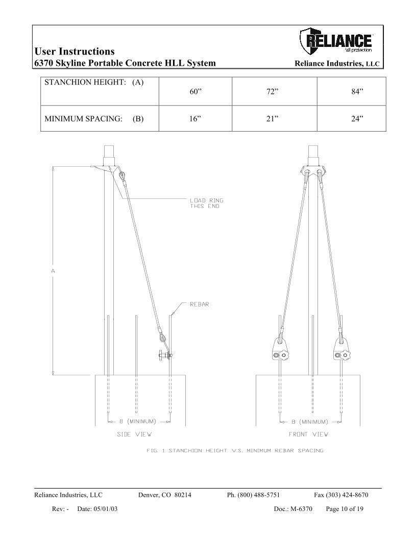
Chart 1. Stanchion Height vs. Tie back Spacing
User Instructions 6370 Skyline Portable Concrete HLL System Reliance Industries, LLC
Reliance Industries, LLC Denver, CO 80214 Ph. (800) 488-5751 Fax (303) 424-8670
Rev: - Date: 05/01/03 Doc.: M-6370 Page 10 of 19
STANCHION HEIGHT: (A)
60” 72” 84”
MINIMUM SPACING: (B) 16” 21” 24”
User Instructions 6370 Skyline Portable Concrete HLL System Reliance Industries, LLC
Reliance Industries, LLC Denver, CO 80214 Ph. (800) 488-5751 Fax (303) 424-8670
Rev: - Date: 05/01/03 Doc.: M-6370 Page 11 of 19
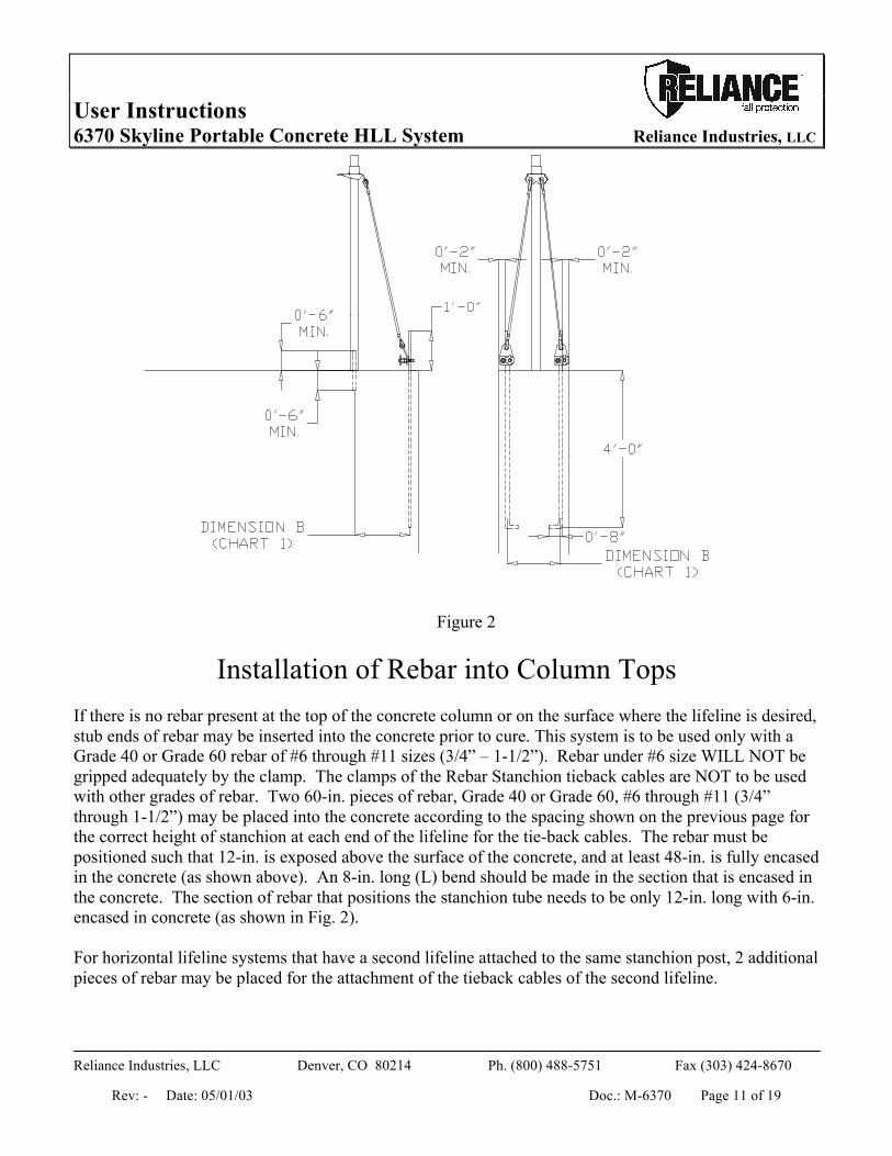
Figure 2
Installation of Rebar into Column Tops If there is no rebar present at the top of the concrete column or on the surface where the lifeline is desired, stub ends of rebar may be inserted into the concrete prior to cure. This system is to be used only with a Grade 40 or Grade 60 rebar of #6 through #11 sizes (3/4” – 1-1/2”). Rebar under #6 size WILL NOT be gripped adequately by the clamp. The clamps of the Rebar Stanchion tieback cables are NOT to be used with other grades of rebar. Two 60-in. pieces of rebar, Grade 40 or Grade 60, #6 through #11 (3/4” through 1-1/2”) may be placed into the concrete according to the spacing shown on the previous page for the correct height of stanchion at each end of the lifeline for the tie-back cables. The rebar must be positioned such that 12-in. is exposed above the surface of the concrete, and at least 48-in. is fully encased in the concrete (as shown above). An 8-in. long (L) bend should be made in the section that is encased in the concrete. The section of rebar that positions the stanchion tube needs to be only 12-in. long with 6-in. encased in concrete (as shown in Fig. 2). For horizontal lifeline systems that have a second lifeline attached to the same stanchion post, 2 additional pieces of rebar may be placed for the attachment of the tieback cables of the second lifeline.
User Instructions 6370 Skyline Portable Concrete HLL System Reliance Industries, LLC
Reliance Industries, LLC Denver, CO 80214 Ph. (800) 488-5751 Fax (303) 424-8670
Rev: - Date: 05/01/03 Doc.: M-6370 Page 12 of 19
The rebar may be used once the concrete has cured to a point that the pullout strength of the rebar is at least 20,000 lbf. Care must be taken to insure that only Grade 40 or Grade 60 rebar is used. The use of other grades of rebar are not permitted for use with this system.
HLL Installation Procedures NOTE: Approved fall protection must be worn during Skyline™ lifeline installation at all times. Do not use the horizontal lifeline or its anchorages as personal fall protection anchorages until the system has been completely installed, inspected, and approved for use by a Qualified Person. 1. Installation of the Skyline™ horizontal lifeline begins with the placement of the end stanchions.
Begin by placing the stanchion tube over an exposed length of rebar in the center of the concrete structure you wish the end of the Horizontal lifeline to begin at. If no rebar is present in the center, a ½” anchor bolt may be installed at this location such that at least 2” is encased in the concrete, and at least 2” is left exposed over the top surface of the concrete. This bolt or rebar section is only needed to keep the bottom of the stanchion tube from slipping outward during a fall arrest. The welded top plate should be at the top end of the assembly. (see fig. 1 )
2. Place the Tie-down bracket over the top of the stanchion. Spin the bracket so that the hole in the bracket where the lifeline will attach to (“the nose”) is pointing towards the location where the second end of the lifeline will be located.
3. The spacing of the rebar that will be used to tie back the stanchion assembly controls the load amplification of the tie back cables. For this reason the safety of the system is determined by controlling this spacing within certain minimum limits. As the stanchions increase in height the minimum rebar spacing must also increase to limit the tie back cable line tension. Fig 1 (stanchion height vs. minimum rebar spacing) shows a typical rebar stanchion assembly and a stanchion height vs. minimum rebar spacing chart. WARNING use only as shown. Do not install system, using rebar spacing less than that shown in the chart. Serious injury or death could result. To install loosen the hand knob on the end of the tieback cable assembly. Slide the U-bolt over the end of the rebar where the tieback cable is to be attached. The cable may be attached to Grade 40 or grade 60, #6 through #11 size rebar (3/4” through 1-1/2”) ONLY! DO NOT USE with any other grade of rebar. Repeat with the second tieback cable.
4. Prior to tightening the hand knob, lean the top of the stanchion tube slightly backward (away from the opposite end of the lifeline). When the horizontal lifeline is properly tensioned this will help insure that the stanchion tubes are vertical.
5. Tighten the hand knobs of the tieback cables as tight as possible by hand. Using a 1-1/4-in. wrench or socket, tighten the nut on the looped bolt to a minimum of 60- to 80-ft. lb.
6. Repeat Step 1 through 5 for the second end of the lifeline. 7. If using the Clamp-on Bypass Bracket for Rebar, Model #6166, install according to the prepared
lifeline diagram following the “Clamp-on Bypass Bracket for Rebar Installation Instructions” supplied with the Bracket.
User Instructions 6370 Skyline Portable Concrete HLL System Reliance Industries, LLC
Reliance Industries, LLC Denver, CO 80214 Ph. (800) 488-5751 Fax (303) 424-8670
Rev: - Date: 05/01/03 Doc.: M-6370 Page 13 of 19
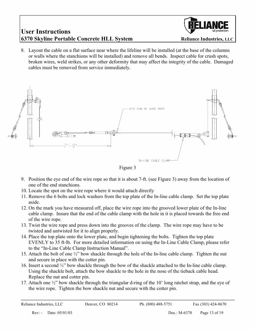
8. Layout the cable on a flat surface near where the lifeline will be installed (at the base of the columns or walls where the stanchions will be installed) and remove all bends. Inspect cable for crush spots, broken wires, weld strikes, or any other deformity that may affect the integrity of the cable. Damaged cables must be removed from service immediately.
Figure 3
9. Position the eye end of the wire rope so that it is about 7-ft. (see Figure 3) away from the location of one of the end stanchions.
10. Locate the spot on the wire rope where it would attach directly 11. Remove the 6 bolts and lock washers from the top plate of the In-line cable clamp. Set the top plate
aside. 12. On the mark you have measured off, place the wire rope into the grooved lower plate of the In-line
cable clamp. Insure that the end of the cable clamp with the hole in it is placed towards the free end of the wire rope.
13. Twist the wire rope and press down into the grooves of the clamp. The wire rope may have to be twisted and untwisted for it to align properly.
14. Place the top plate onto the lower plate, and begin tightening the bolts. Tighten the top plate EVENLY to 35 ft-lb. For more detailed information on using the In-Line Cable Clamp, please refer to the “In-Line Cable Clamp Instruction Manual”.
15. Attach the bolt of one ½” bow shackle through the hole of the In-line cable clamp. Tighten the nut and secure in place with the cotter pin.
16. Insert a second ½” bow shackle through the bow of the shackle attached to the In-line cable clamp. Using the shackle bolt, attach the bow shackle to the hole in the nose of the tieback cable head. Replace the nut and cotter pin.
17. Attach one ½” bow shackle through the triangular d-ring of the 10’ long ratchet strap, and the eye of the wire rope. Tighten the bow shackle nut and secure with the cotter pin.
User Instructions 6370 Skyline Portable Concrete HLL System Reliance Industries, LLC
Reliance Industries, LLC Denver, CO 80214 Ph. (800) 488-5751 Fax (303) 424-8670
Rev: - Date: 05/01/03 Doc.: M-6370 Page 14 of 19
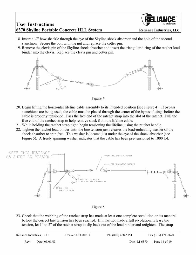
18. Insert a ½” bow shackle through the eye of the Skyline shock absorber and the hole of the second stanchion. Secure the bolt with the nut and replace the cotter pin.
19. Remove the clevis pin of the Skyline shock absorber and insert the triangular d-ring of the ratchet load binder into the clevis. Replace the clevis pin and cotter pin.
Figure 4 20. Begin lifting the horizontal lifeline cable assembly to its intended position (see Figure 4). If bypass
stanchions are being used, the cable must be placed through the center of the bypass fittings before the cable is properly tensioned. Pass the free end of the ratchet strap into the slot of the ratchet. Pull the free end of the ratchet strap to help remove slack from the lifeline cable.
21. While holding the ratchet strap tight, begin tensioning the lifeline, using the ratchet handle. 22. Tighten the ratchet load binder until the line tension just releases the load-indicating washer of the
shock absorber to spin free. This washer is located just under the eye of the shock absorber (see Figure 5). A freely spinning washer indicates that the cable has been pre-tensioned to 1000 lbf.
Figure 5 23. Check that the webbing of the ratchet strap has made at least one complete revolution on its mandrel
before the correct line tension has been reached. If it has not made a full revolution, release the tension, let 1” to 2” of the ratchet strap to slip back out of the load binder and retighten. The strap
User Instructions 6370 Skyline Portable Concrete HLL System Reliance Industries, LLC
Reliance Industries, LLC Denver, CO 80214 Ph. (800) 488-5751 Fax (303) 424-8670
Rev: - Date: 05/01/03 Doc.: M-6370 Page 15 of 19
should now make at least one full revolution before the lifeline is properly tensioned. At least one full revolution is necessary for the tensioner to overcome the maximum load with out slipping.
24. Inspect the installation for any defects, such as missing parts, damage, proper anchorage strengths and configuration, proper pre-tensioning, proper cable alignment, proper elevation, defective or non-compatible components. DO NOT authorize system use if any defects or discrepancies are found. Check system installation parameters with system installation parameter documents to assure that the correct installation has been performed.
25. Once the system passes all checks by the competent person, the system may be approved for use, and labeled with a permanent identification tag referencing the following information:
a. Identification number that will tie the lifeline to the correct computer generated design documents that identify the original design parameters.
b. Date of installation. c. Total authorized span length and sub-span length. d. Total number of people allowed on the system at one time. e. The minimum required clearance (MRC) below the walking/working surface. f. The anticipated maximum line tension. g. The required cable pre-tension (normally 1000-lbs.)
26. A separate tag should also be added indicating date of last inspection by the competent person.
Training It is the responsibility of the employer to train all workers prior to using this system (per OSHA 1926.503 (a)(1)). The employer shall provide a training program for each employee who might be exposed to fall hazards. The program shall enable each employee to recognize the hazards of falling and shall train each employee in the procedures to be followed in order to minimize these hazards. The employer shall assure that, as necessary, each employee has been trained by a competent person qualified in the following areas: a. OSHA regulations governing the use of horizontal lifelines. b. Ability to recognize potential fall and workplace hazards. c. Method of inspection of safety equipment. d. Rescue procedures. e. Installation and removal techniques.
User Instructions 6370 Skyline Portable Concrete HLL System Reliance Industries, LLC
Reliance Industries, LLC Denver, CO 80214 Ph. (800) 488-5751 Fax (303) 424-8670
Rev: - Date: 05/01/03 Doc.: M-6370 Page 16 of 19
Planning for Rescue Prior to system use, a rescue plan must be prepared, the workers must be trained in its use, and the rescue equipment must be on hand to implement it in case of a fall. Typical rescue plans include (but are not limited to) the following items:
1. List of equipment that must be readily accessible in the event of an emergency and the names of those workers certified to use or operate that equipment.
2. Emergency contact phone numbers (ambulance, hospital, fire department…) and a means to contact them (cell phone, emergency radio).
3. List of employees on the site, and the specific tasks they will perform to effect the rescue. 4. If a confined spacing is to be entered a confined space work permit must be filed and approved.
During installation of horizontal lifeline systems, anchorage points should be identified, and clearly marked in such a manner as to provide a means to rescue a worker at any position along the lifeline system.
Inspection Prior to each use, the worker must inspect the system for any physical damage, wear, corrosion, or malfunctioning parts. Check the shock absorber for deployment by looking to see if the black slide bearing under the shock absorber eye is exposed. Once the shock absorber is deployed, its energy capacity is used up, and it cannot be reset. If the shock absorber deploys, the entire system has seen a fall arrest load and must be removed from service until it is inspected by a competent person who either replaces or repairs and re-certifies the components for use on the system. Once deployed, shock absorbers are not re-usable, and must be replaced. If an inspection reveals a problem or unsafe condition, remove the entire system from service until it can be re-certified by a competent person. The worker, who must also check the pre-tension prior to each use, must inspect all system components. A formal inspection must be carried out a minimum of once each year, and be formally documented and kept on file with the system parameter documents.
Servicing A qualified person trained in the inspection and servicing of system components must carry out servicing of this system. The company’s safety officer should maintain a record log of all servicing and inspection dates. The system and all components must be withdrawn from service if subjected to fall arrest forces. Those components may be returned to service only after being certified by a qualified person. Only original Reliance Industries equipment or replacement parts are approved for use in this system. Contact Reliance Industries Engineering with questions and when in need of assistance.
User Instructions 6370 Skyline Portable Concrete HLL System Reliance Industries, LLC
Reliance Industries, LLC Denver, CO 80214 Ph. (800) 488-5751 Fax (303) 424-8670
Rev: - Date: 05/01/03 Doc.: M-6370 Page 17 of 19
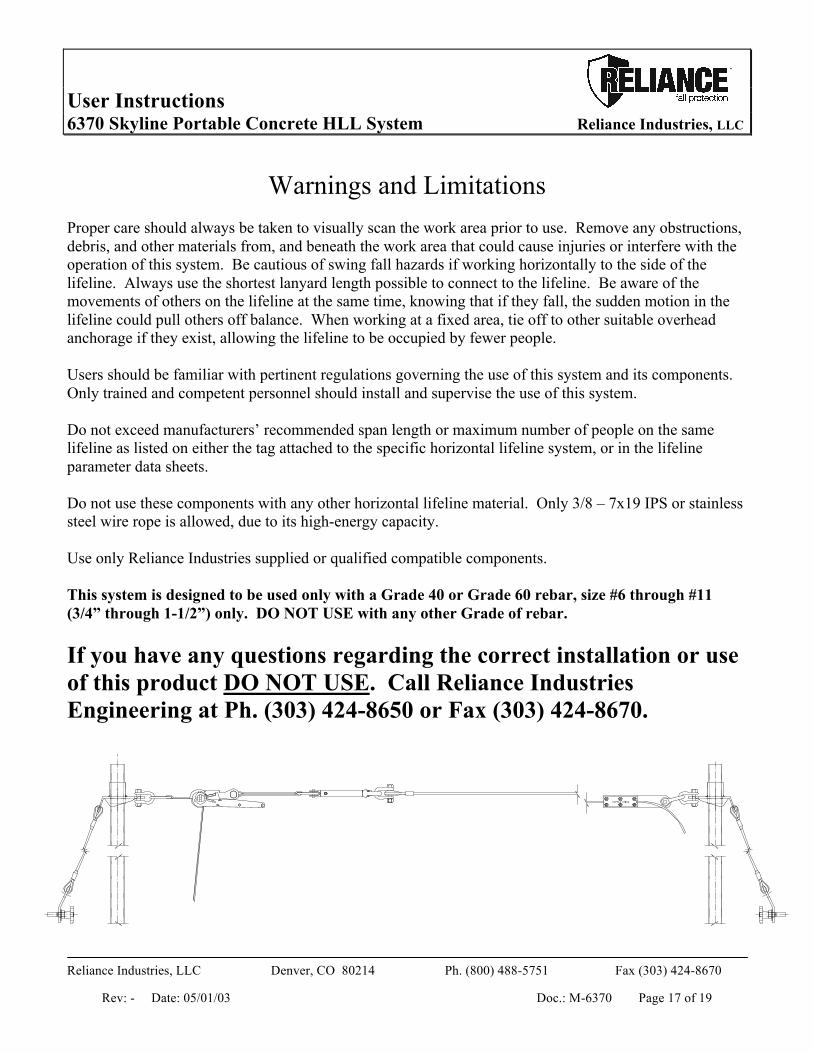
Warnings and Limitations Proper care should always be taken to visually scan the work area prior to use. Remove any obstructions, debris, and other materials from, and beneath the work area that could cause injuries or interfere with the operation of this system. Be cautious of swing fall hazards if working horizontally to the side of the lifeline. Always use the shortest lanyard length possible to connect to the lifeline. Be aware of the movements of others on the lifeline at the same time, knowing that if they fall, the sudden motion in the lifeline could pull others off balance. When working at a fixed area, tie off to other suitable overhead anchorage if they exist, allowing the lifeline to be occupied by fewer people. Users should be familiar with pertinent regulations governing the use of this system and its components. Only trained and competent personnel should install and supervise the use of this system. Do not exceed manufacturers’ recommended span length or maximum number of people on the same lifeline as listed on either the tag attached to the specific horizontal lifeline system, or in the lifeline parameter data sheets. Do not use these components with any other horizontal lifeline material. Only 3/8 – 7x19 IPS or stainless steel wire rope is allowed, due to its high-energy capacity. Use only Reliance Industries supplied or qualified compatible components. This system is designed to be used only with a Grade 40 or Grade 60 rebar, size #6 through #11 (3/4” through 1-1/2”) only. DO NOT USE with any other Grade of rebar. If you have any questions regarding the correct installation or use of this product DO NOT USE. Call Reliance Industries Engineering at Ph. (303) 424-8650 or Fax (303) 424-8670.

Inspection Log for HLL Systems Company: _____________________ Location:___________________ Date:__________ Job Site: ______________________ HLL Log No.: ______________ System No.: _____ Is this system used as described in the HLL Log No. _____ to conform to design document criteria?_______ Describe non-conforming conditions in the boxes below:
Inspection Criteria
Missing Parts
Labels Readable
Corrosion
Deformed Parts
Cracked Parts/ Broken wires
Excessive Loading
HLL Identity Tag HLL Shock Absorber Label HLL Shock Absorber In-Line Cable Clamp End fittings(bow shackles) Shackles Wire Rope Webbing Strap Ratchet Tensioner Stanchions Tie Back Cables Is Shock Absorber pre-tension set correctly____________ Has a Rescue Plan been prepared____________________ Is Rescue Equipment on hand______________________ Have workers been trained in the Rescue Procedures and been given a copy of the Rescue Plan_______________
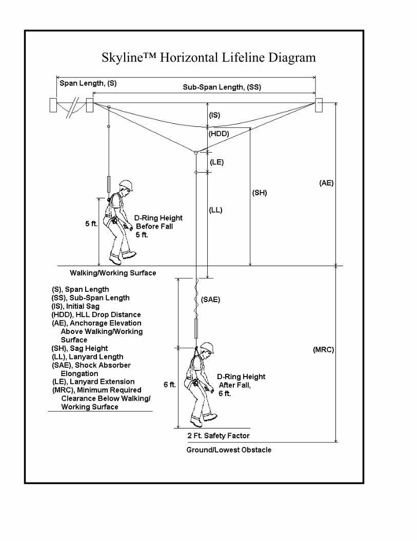
Skyline™ Horizontal Lifeline Diagram