Embed Size (px)
Citation preview
Marshall UniversityMarshall Digital Scholar
Biological Sciences Faculty Research Biological Sciences
Spring 5-5-2012
Remarkable resilience of teeth (How are Teeth soBrittle yet so Resilient)Paul J. ConstantinoMarshall University, [email protected]
Follow this and additional works at: http://mds.marshall.edu/bio_sciences_faculty
Part of the Biological and Physical Anthropology Commons, Biology Commons, and the OtherDentistry Commons
This Article is brought to you for free and open access by the Biological Sciences at Marshall Digital Scholar. It has been accepted for inclusion inBiological Sciences Faculty Research by an authorized administrator of Marshall Digital Scholar. For more information, please [email protected], [email protected].
Recommended CitationChai H, Lee JJ-W, Constantino PJ, Lucas PW, Lawn BR. Remarkable resilience of teeth. Proceedings of the National Academy ofSciences 106:7289-7293.
1
How are Teeth so Brittle yet so Resilient?
Herzl Chai,1 James J-W Lee,2,3 Paul J Constantino,2 Peter W Lucas,2
Brian R Lawn3
1 School of Mechanical Engineering, Tel Aviv University, Tel Aviv, Israel 2 Department of Anthropology, George Washington University, Washington DC, USA 3 Ceramics Division, National Institute of Standards and Technology, Gaithersburg, USA
* Email: [email protected]
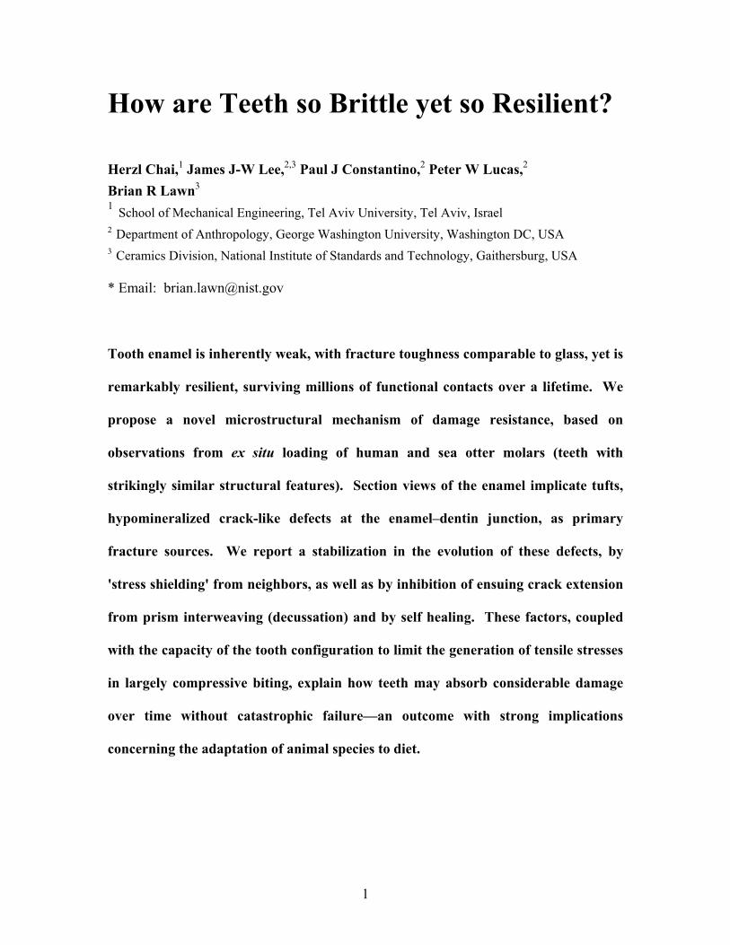
Tooth enamel is inherently weak, with fracture toughness comparable to glass, yet is
remarkably resilient, surviving millions of functional contacts over a lifetime. We
propose a novel microstructural mechanism of damage resistance, based on
observations from ex situ loading of human and sea otter molars (teeth with
strikingly similar structural features). Section views of the enamel implicate tufts,
hypomineralized crack-like defects at the enamel–dentin junction, as primary
fracture sources. We report a stabilization in the evolution of these defects, by
'stress shielding' from neighbors, as well as by inhibition of ensuing crack extension
from prism interweaving (decussation) and by self healing. These factors, coupled
with the capacity of the tooth configuration to limit the generation of tensile stresses
in largely compressive biting, explain how teeth may absorb considerable damage
over time without catastrophic failure—an outcome with strong implications
concerning the adaptation of animal species to diet.
2
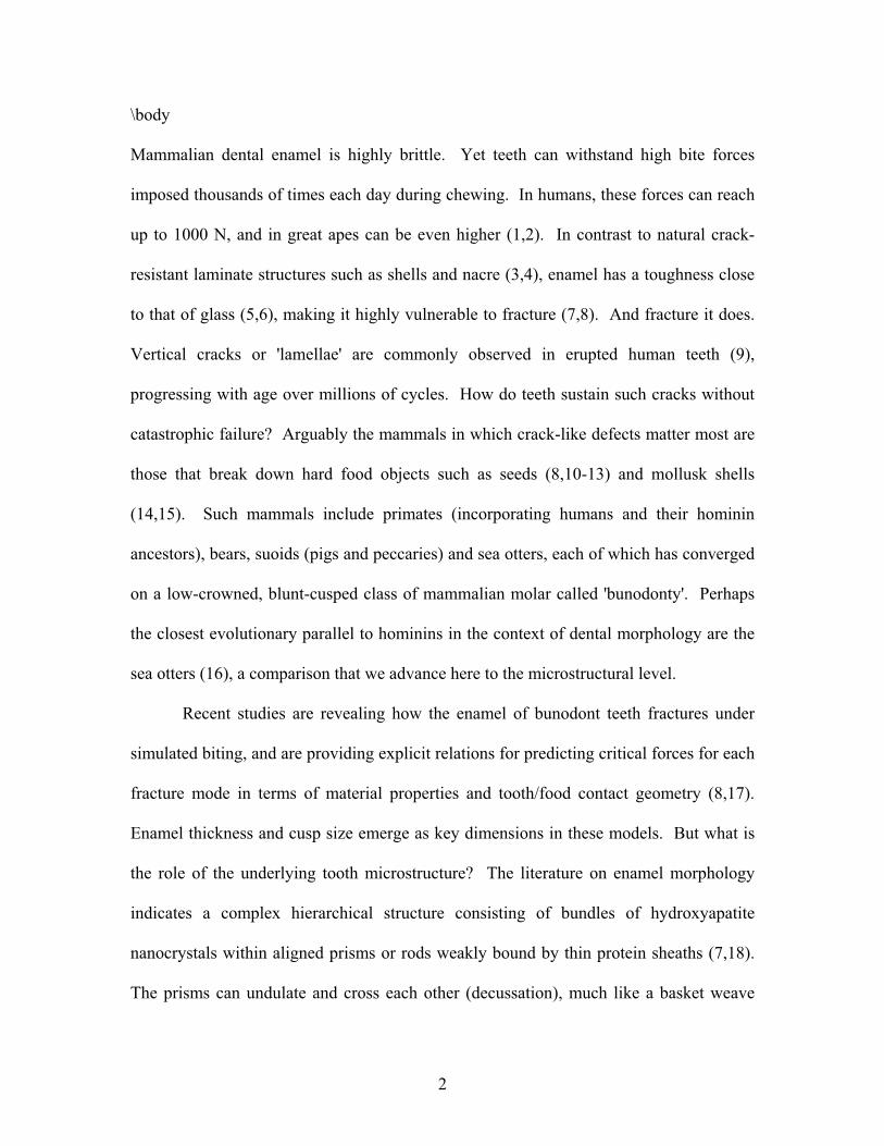
\body
Mammalian dental enamel is highly brittle. Yet teeth can withstand high bite forces
imposed thousands of times each day during chewing. In humans, these forces can reach
up to 1000 N, and in great apes can be even higher (1,2). In contrast to natural crack-
resistant laminate structures such as shells and nacre (3,4), enamel has a toughness close
to that of glass (5,6), making it highly vulnerable to fracture (7,8). And fracture it does.
Vertical cracks or 'lamellae' are commonly observed in erupted human teeth (9),
progressing with age over millions of cycles. How do teeth sustain such cracks without
catastrophic failure? Arguably the mammals in which crack-like defects matter most are
those that break down hard food objects such as seeds (8,10-13) and mollusk shells
(14,15). Such mammals include primates (incorporating humans and their hominin
ancestors), bears, suoids (pigs and peccaries) and sea otters, each of which has converged
on a low-crowned, blunt-cusped class of mammalian molar called 'bunodonty'. Perhaps
the closest evolutionary parallel to hominins in the context of dental morphology are the
sea otters (16), a comparison that we advance here to the microstructural level.
Recent studies are revealing how the enamel of bunodont teeth fractures under
simulated biting, and are providing explicit relations for predicting critical forces for each
fracture mode in terms of material properties and tooth/food contact geometry (8,17).
Enamel thickness and cusp size emerge as key dimensions in these models. But what is
the role of the underlying tooth microstructure? The literature on enamel morphology
indicates a complex hierarchical structure consisting of bundles of hydroxyapatite
nanocrystals within aligned prisms or rods weakly bound by thin protein sheaths (7,18).
The prisms can undulate and cross each other (decussation), much like a basket weave
3
(18,19). Enamel also contains arrays of intrinsic defects, principally hypocalcified
fissures that emanate from the enamel–dentin junction (EDJ). These defects have the
characteristics of 'closed cracks' filled with organic matter, and are known as 'tufts' for
their wavy appearance within the prism microstructure (18,20,21). They are now
believed to be a primary source of the fractures that ultimately develop in tooth enamel
during extended function or overloading (22).
In this study we examine the fundamental nature of tooth resilience—and
weakness—by conducting ex situ loading tests on extracted human and sea otter molars
and examining the sources of fracture in sections of post-loaded specimens. We argue
that enamel, while not macroscopically tough, nevertheless contains elements in its
geometrical and microstructural complexion that confer a certain damage tolerance on the
composite tooth structure. Such damage tolerance has long been argued to be an
important factor in the adaptation of mammalian dentition to diet (13,23). It is also of
interest in the context of biomimicry, in which dental researchers look to nature for
inspiration in next-generation biomaterials design. We explore these connection further
here.
Experiment and Analysis
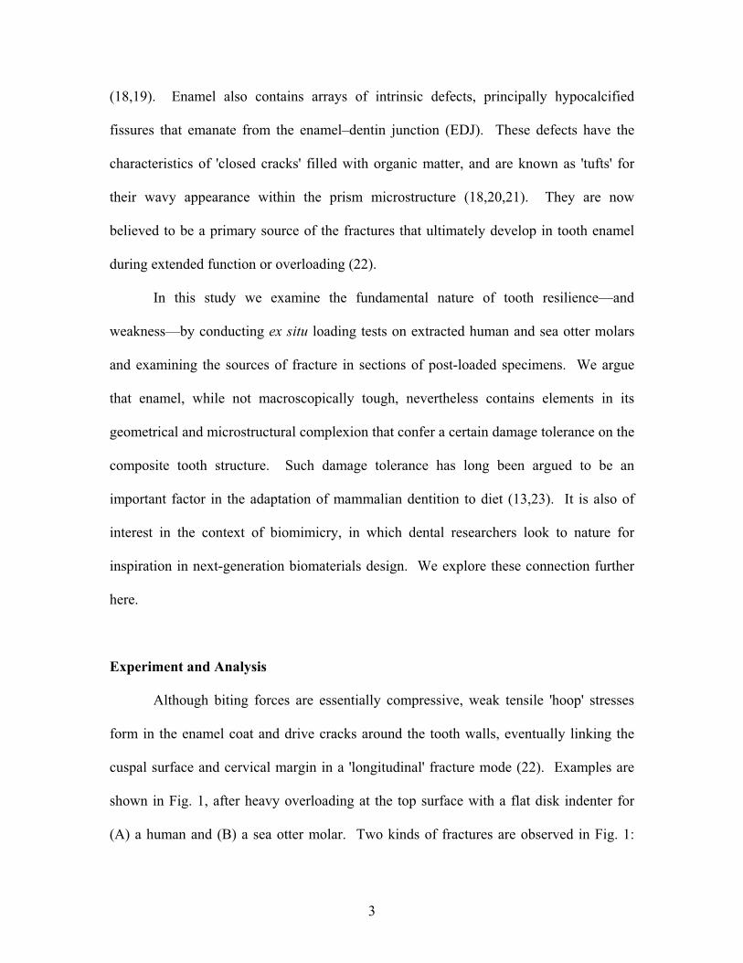
Although biting forces are essentially compressive, weak tensile 'hoop' stresses
form in the enamel coat and drive cracks around the tooth walls, eventually linking the
cuspal surface and cervical margin in a 'longitudinal' fracture mode (22). Examples are
shown in Fig. 1, after heavy overloading at the top surface with a flat disk indenter for
(A) a human and (B) a sea otter molar. Two kinds of fractures are observed in Fig. 1:
4
'radial–median' cracks (R), initiating from the near-contact zone and propagating
downward around the side walls; and 'margin' cracks (M), initiating from the cervical
base and propagating upward. These same cracks find it difficult to enter the tougher,
stress-shielded dentin (6,24); however, at higher loads they can link up to produce
spalling of the enamel away from the dentin (25). The key observation is a substantial
increase in load required to drive the cracks from inception to completion—hence the
damage tolerance (22). This fracture resistance will be augmented by the filling of any
slow growing fissures with organic fluids (9,26), thereby 'gluing' the crack walls together
(self-healing) (27).
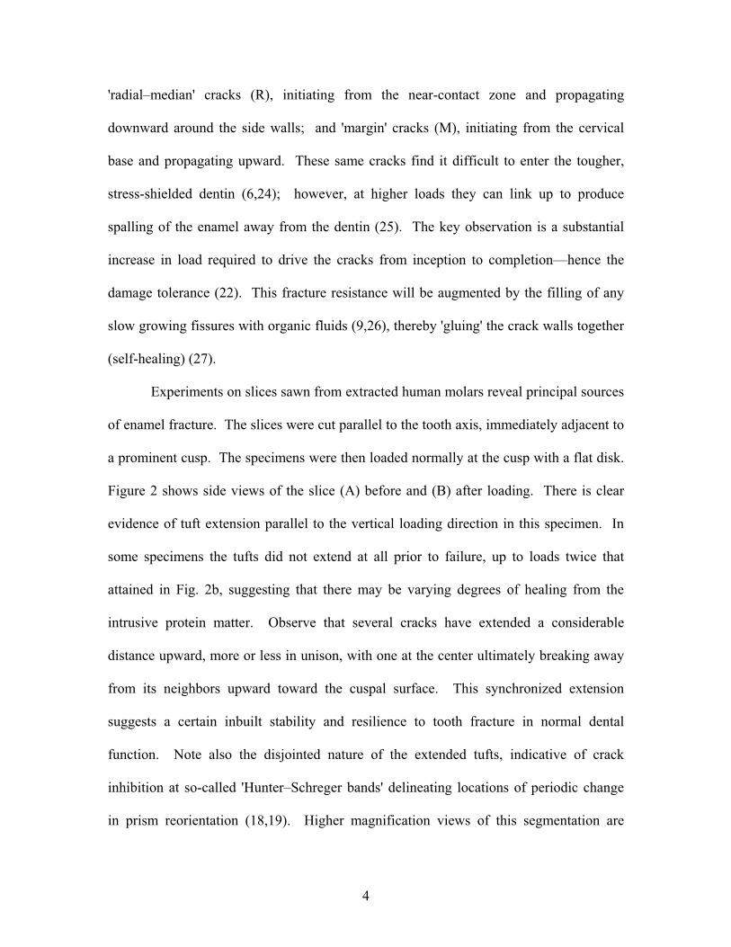
Experiments on slices sawn from extracted human molars reveal principal sources
of enamel fracture. The slices were cut parallel to the tooth axis, immediately adjacent to
a prominent cusp. The specimens were then loaded normally at the cusp with a flat disk.
Figure 2 shows side views of the slice (A) before and (B) after loading. There is clear
evidence of tuft extension parallel to the vertical loading direction in this specimen. In
some specimens the tufts did not extend at all prior to failure, up to loads twice that
attained in Fig. 2b, suggesting that there may be varying degrees of healing from the
intrusive protein matter. Observe that several cracks have extended a considerable
distance upward, more or less in unison, with one at the center ultimately breaking away
from its neighbors upward toward the cuspal surface. This synchronized extension
suggests a certain inbuilt stability and resilience to tooth fracture in normal dental
function. Note also the disjointed nature of the extended tufts, indicative of crack
inhibition at so-called 'Hunter–Schreger bands' delineating locations of periodic change
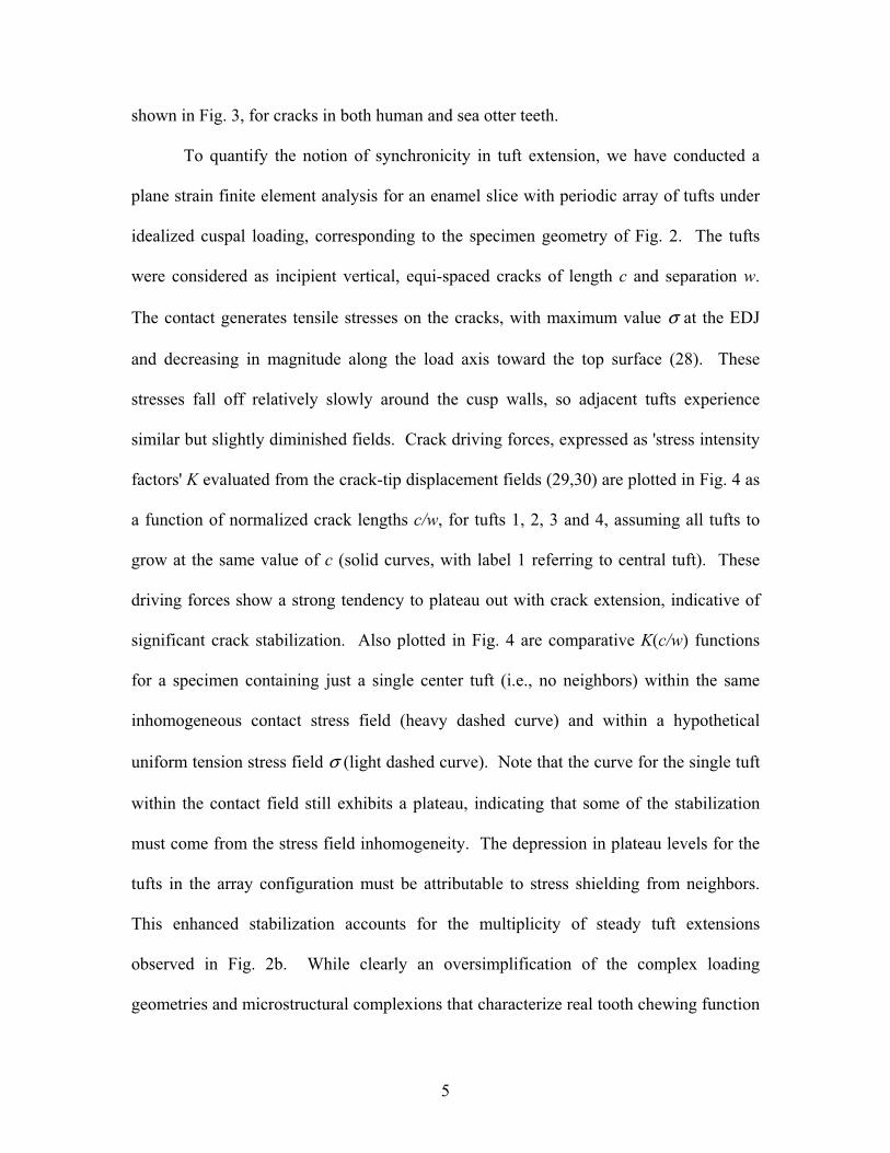
in prism reorientation (18,19). Higher magnification views of this segmentation are
5
shown in Fig. 3, for cracks in both human and sea otter teeth.
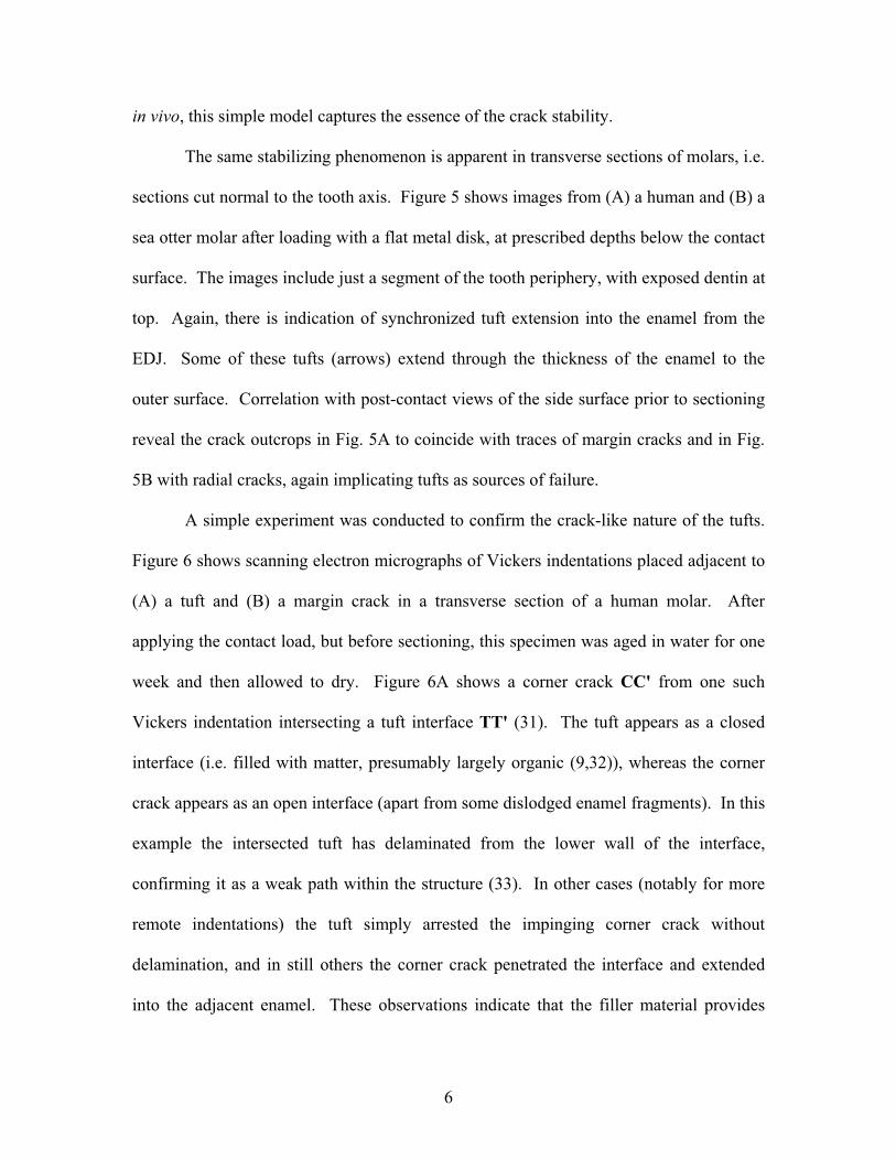
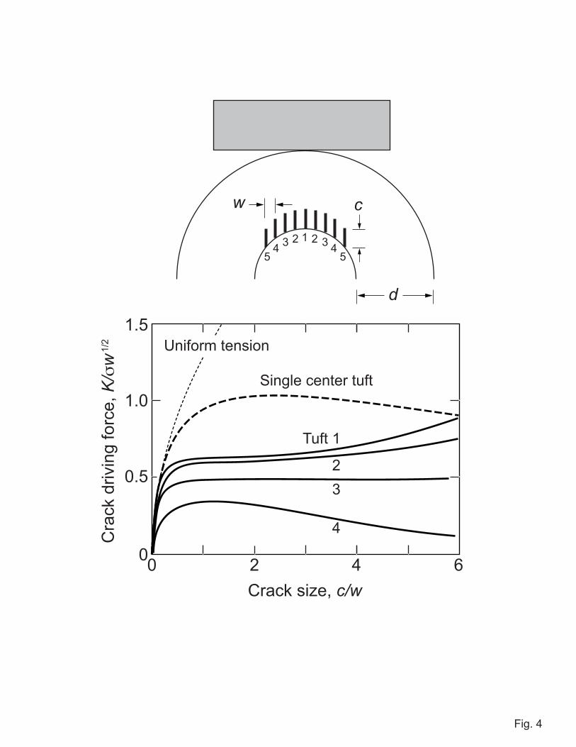
To quantify the notion of synchronicity in tuft extension, we have conducted a
plane strain finite element analysis for an enamel slice with periodic array of tufts under
idealized cuspal loading, corresponding to the specimen geometry of Fig. 2. The tufts
were considered as incipient vertical, equi-spaced cracks of length c and separation w.
The contact generates tensile stresses on the cracks, with maximum value σ at the EDJ
and decreasing in magnitude along the load axis toward the top surface (28). These
stresses fall off relatively slowly around the cusp walls, so adjacent tufts experience
similar but slightly diminished fields. Crack driving forces, expressed as 'stress intensity
factors' K evaluated from the crack-tip displacement fields (29,30) are plotted in Fig. 4 as
a function of normalized crack lengths c/w, for tufts 1, 2, 3 and 4, assuming all tufts to
grow at the same value of c (solid curves, with label 1 referring to central tuft). These
driving forces show a strong tendency to plateau out with crack extension, indicative of
significant crack stabilization. Also plotted in Fig. 4 are comparative K(c/w) functions
for a specimen containing just a single center tuft (i.e., no neighbors) within the same
inhomogeneous contact stress field (heavy dashed curve) and within a hypothetical
uniform tension stress field σ (light dashed curve). Note that the curve for the single tuft
within the contact field still exhibits a plateau, indicating that some of the stabilization
must come from the stress field inhomogeneity. The depression in plateau levels for the
tufts in the array configuration must be attributable to stress shielding from neighbors.
This enhanced stabilization accounts for the multiplicity of steady tuft extensions
observed in Fig. 2b. While clearly an oversimplification of the complex loading
geometries and microstructural complexions that characterize real tooth chewing function
6
in vivo, this simple model captures the essence of the crack stability.
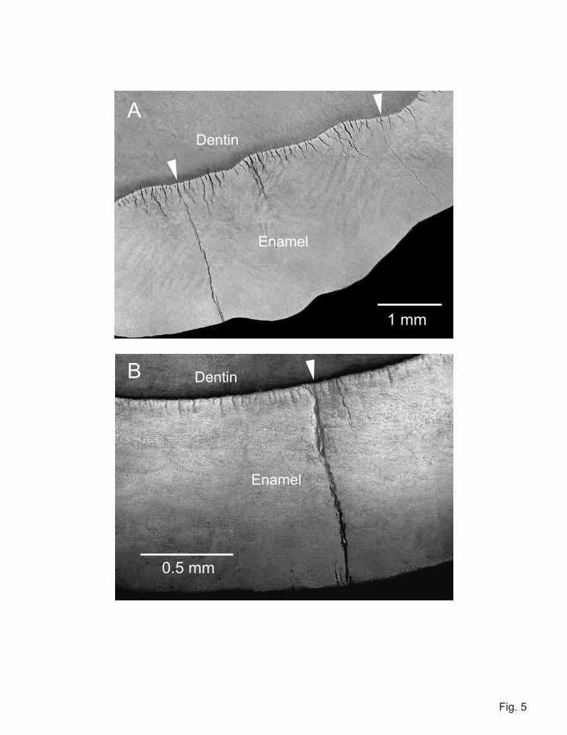
The same stabilizing phenomenon is apparent in transverse sections of molars, i.e.
sections cut normal to the tooth axis. Figure 5 shows images from (A) a human and (B) a
sea otter molar after loading with a flat metal disk, at prescribed depths below the contact
surface. The images include just a segment of the tooth periphery, with exposed dentin at
top. Again, there is indication of synchronized tuft extension into the enamel from the
EDJ. Some of these tufts (arrows) extend through the thickness of the enamel to the
outer surface. Correlation with post-contact views of the side surface prior to sectioning
reveal the crack outcrops in Fig. 5A to coincide with traces of margin cracks and in Fig.
5B with radial cracks, again implicating tufts as sources of failure.
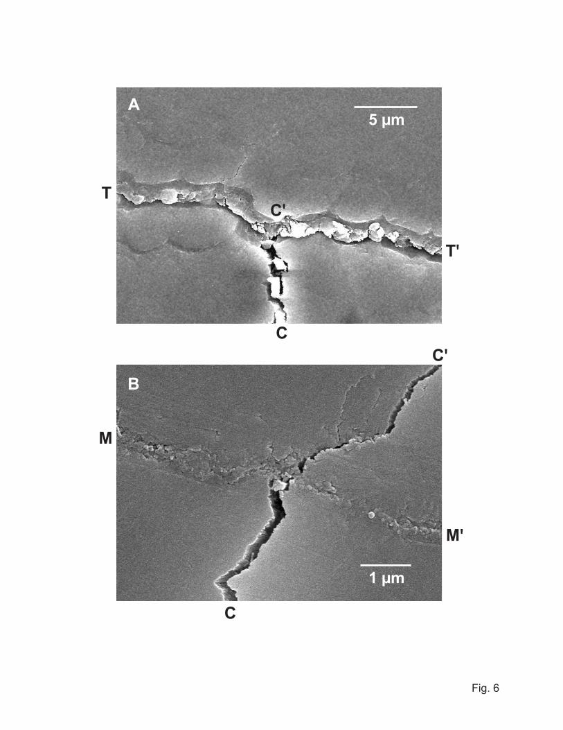
A simple experiment was conducted to confirm the crack-like nature of the tufts.
Figure 6 shows scanning electron micrographs of Vickers indentations placed adjacent to
(A) a tuft and (B) a margin crack in a transverse section of a human molar. After
applying the contact load, but before sectioning, this specimen was aged in water for one
week and then allowed to dry. Figure 6A shows a corner crack CC' from one such
Vickers indentation intersecting a tuft interface TT' (31). The tuft appears as a closed
interface (i.e. filled with matter, presumably largely organic (9,32)), whereas the corner
crack appears as an open interface (apart from some dislodged enamel fragments). In this
example the intersected tuft has delaminated from the lower wall of the interface,
confirming it as a weak path within the structure (33). In other cases (notably for more
remote indentations) the tuft simply arrested the impinging corner crack without
delamination, and in still others the corner crack penetrated the interface and extended
into the adjacent enamel. These observations indicate that the filler material provides
7
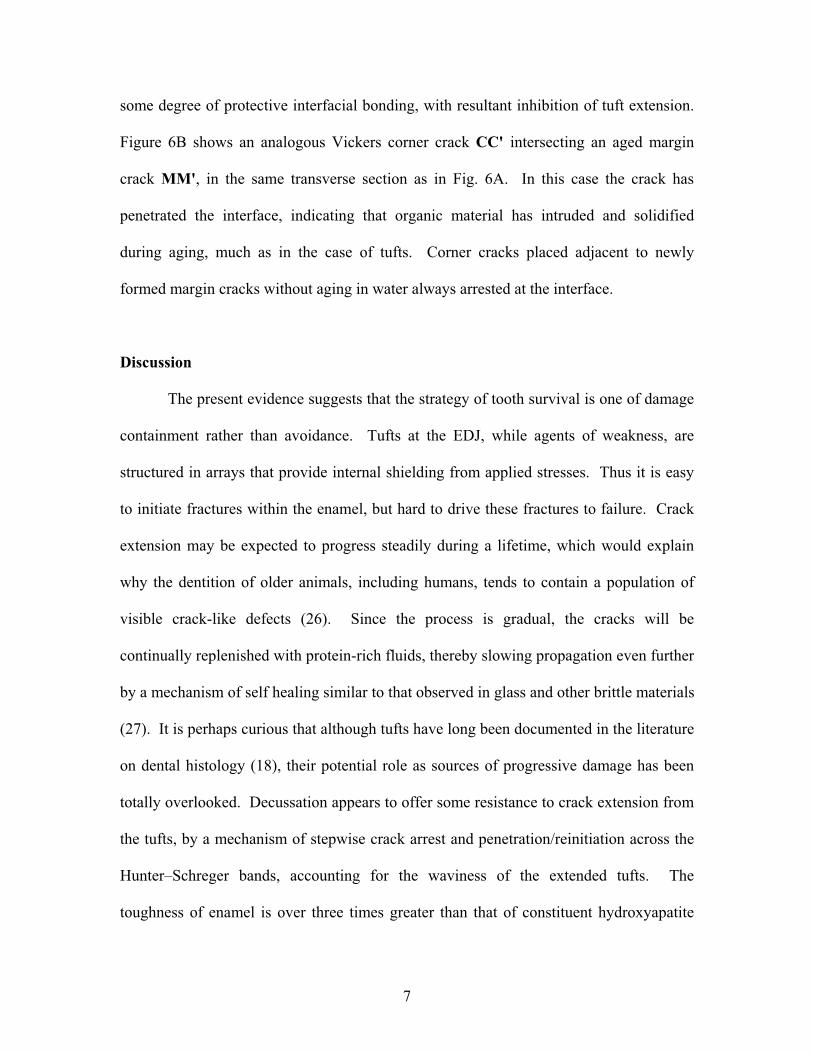
some degree of protective interfacial bonding, with resultant inhibition of tuft extension.
Figure 6B shows an analogous Vickers corner crack CC' intersecting an aged margin
crack MM', in the same transverse section as in Fig. 6A. In this case the crack has
penetrated the interface, indicating that organic material has intruded and solidified
during aging, much as in the case of tufts. Corner cracks placed adjacent to newly
formed margin cracks without aging in water always arrested at the interface.
Discussion
The present evidence suggests that the strategy of tooth survival is one of damage
containment rather than avoidance. Tufts at the EDJ, while agents of weakness, are
structured in arrays that provide internal shielding from applied stresses. Thus it is easy
to initiate fractures within the enamel, but hard to drive these fractures to failure. Crack
extension may be expected to progress steadily during a lifetime, which would explain
why the dentition of older animals, including humans, tends to contain a population of
visible crack-like defects (26). Since the process is gradual, the cracks will be
continually replenished with protein-rich fluids, thereby slowing propagation even further
by a mechanism of self healing similar to that observed in glass and other brittle materials
(27). It is perhaps curious that although tufts have long been documented in the literature
on dental histology (18), their potential role as sources of progressive damage has been
totally overlooked. Decussation appears to offer some resistance to crack extension from
the tufts, by a mechanism of stepwise crack arrest and penetration/reinitiation across the
Hunter–Schreger bands, accounting for the waviness of the extended tufts. The
toughness of enamel is over three times greater than that of constituent hydroxyapatite
8
crystallites within the prisms (34). The fracture patterns in Fig. 3 are reminiscent of those
in brittle cross-ply laminate composites (35). Decussation occurs in different degrees in
different animals, but generally with higher densities in the regions of the EDJ where the
tufts originate (8). This implied resistance would appear to compensate somewhat for the
intrinsic weakness of the inter-prism paths—without it, the toughness on pathways
parallel to the prisms would be even lower than that of glass. The toughness of human
enamel for crack paths perpendicular to the prisms is considerably higher relative to paths
parallel to the prisms (5,6), making enamel more resistant to potentially deleterious
lateral chipping (36).
The relationship of tooth form to diet remains a crucial issue in mammalian
evolution. Such an understanding is vital to paleontologists and paleoanthropologists
because teeth constitute a large portion of the fossil record (13). Arguments have been
made asserting that such critical elements as enamel thickness, and to some extent tooth
size, act as optimal organizations to frustrate tooth failure in relation to diet
(8,13,17,22,37-39). However, it would seem that enamel microstructure, and especially
tufts, are also important factors. The presence of tufts would appear to be a common
feature of animal dentition, especially in primates: we have observed similar structures in
enamel sections from chimps, orangutans and gorillas. Apart from their role in stress
shielding, tuft arrays may protect the dentin by increasing the local enamel compliance,
effectively 'grading' the material properties in the region of the EDJ (40). It is thus likely
that the damage tolerance conferred by these defects is intricately tied to tooth
morphology and function along the evolutionary path. The specific nature of the cuspal
loading is another factor in determining which ensuing damage mode will dominate, and
9
this in turn depends on diet. For chewing on small hard particulates, the principal
damage mode is wear in the cuspal zone (8). Since wear is a local process relating to
asperity contact at the external surface, tuft configurations and decussation within the
enamel interior would be unlikely to confer much benefit. For feeding on large objects,
such as nuts and seeds, the greater threat is from longitudinal fracture (8,17). It is
noteworthy that mammals that consume large hard foods, including some primates, sea
otters and giant pandas, tend to show significant decussation in the inner sections of their
tooth enamel (41). In these cases, stress shielding, internal fissure self-healing, and prism
decussation adjacent to the EDJ—in conjunction with thick enamel and large cuspal
radius—offer inbuilt protection against catastrophic failure from dietary stresses.
Scientists in various disciplines may draw from the findings reported here. For
the large body of biologists concerned with the evolution of teeth, it suggests that largely
overlooked intrinsic structures like tufts may play a vital role in the interplay between
internal weakness of enamel and damage tolerance of the integrated tooth structure. Do
all enamels possess these features or are they linked predominantly to bunodonty? For
those biomaterials researchers who look to biomimicry for inspiration in the design of
synthetic enamel replacements (as well as of bone and soft tissue), the replication of
hierarchical fibrous microstructures incorporating weak internal interfaces presents a
fascinating challenge. Bio-inspired laminate structures that make use of weak internal
interfaces to confer toughness, analogous to shells and nacre, constitute just one example
of this design philosophy (42). To make any use of such biomimicry, it is crucial that we
first understand the underlying micromechanics that determine the structural resilience.
Unlike most artificial structures, mammalian systems have a natural inbuilt capacity for
10
self-healing—in the present case from protein-rich fluids in the dentition—that will tend
to mitigate susceptibility to cyclic fatigue. Even this last element lies within the realms
of possibility, as has been demonstrated by incorporation of microcapsulated crack-
release healing agents into polymer microstructures (43). The future development of
such damage-tolerant structures rests with the next generation of innovators.
Materials and Methods
Human molar and premolar teeth for testing were provided by Gary Schumacher and
Sabine Dickens of the American Dental Association (ADA) laboratories at the National
Institute of Standards and Technology (NIST). The teeth were extracted from male and
female patients 18 to 25 years old and stored in aqueous solution. Intact specimens were
selected and cleaned by Anthony Guiseppetti at the ADA. Cursory examination of the
surfaces of the as-received teeth revealed the pre-existence of crack-like defects of
various lengths extending from the cervical–enamel margins longitudinally toward the
cuspal area. The average tooth width was 10 mm and crown height 7.5 mm. Approval to
test these specimens was granted by the NIST Internal Review Board. The specimens
were kept in aqueous solution after receipt and were kept moist during subsequent
preparation and testing. Sea otter molar and premolar teeth were supplied by Jim Estes
and Nate Dominy of the University of California at Santa Cruz (UCSC). These were
from the skulls of deceased animals that had been dissected, cleaned and frozen by Andy
Cunningham at UCSC before shipping to us in a dry state. Permission to transport and
test the sea otter teeth was granted by Melissa Miller of the California Department of Fish
and Game. Upon receipt, the teeth were extracted from the mandibles and stored in water.
All remains of these animals are ultimately to be lodged at the California Academy of
Sciences.
The photos of human and otter molars in Fig. 1 were obtained from specimens
11
after subjection to a compression fracture test (17). Individual teeth were mounted with
their roots embedded in epoxy blocks, cusps uppermost. The mounted specimens were
placed onto the platform of a mechanical testing machine, and kept moist during testing
by continually squirting drops from a water bottle. A flat tungsten carbide rod was used
to apply a vertical load to the most prominent cusp of each tooth. A video camera was
used to view the progress of the cracks in situ around the buccal or lingual walls
immediately adjacent to the indented cusp during the loading. Oblique lighting was
adjusted to provide optimum contrast at the fracture sites.
Sections through the teeth were made by conventional grinding and polishing.
Images of the sections were obtained using reflection optical microscopy and scanning
electron microscopy. The longitudinal slices in Figs. 2 and 3 were obtained with a
diamond saw. Two cuts 1.5 mm apart were made either side of a selected cusp, parallel
to the prospective vertical load axis. The resulting faces were polished to 1 µm finish
with diamond paste. The slices were then mounted into epoxy blocks, and loaded with a
tungsten carbide rod, as described above. Again, a video camera was used to photograph
the tuft responses in the region of the EDJ. The transverse tooth sections in Figs. 5 and 6
were prepared by serial grinding and polishing of indented specimens, once more to 1 µm
finish. These sections were polished to prescribed depths below the indented cusp.
Finite element analysis (FEA) was used to determine stress intensity factors for
the crack array shown in the inset of Fig. 4. A mesh was set up for a curved
enamel/dentin bilayer slice of depth 1.5 mm, with enamel thickness d = 1.8 mm and outer
radius 3 mm, using a standard ANSYS finite element package. Young's modulus and
Poisson's ratio were taken as 90 GPa and 0.22 for enamel, 18 GPa and 0.35 for dentin.
Some 9 cracks of size c and spacing w = 0.1 mm incorporated into the enamel coat,
labeled 1, 2, 3, 4, 5 as shown. A concentrated load was then applied at the top of the cusp
by a rigid flat indenter. The mesh was scaled to smaller grid size in the vicinity of the
crack tips, and the configuration refined until the solutions reached convergence. The
12
displacement fields near the tip of the cracks were thus determined, from which the stress
intensity factor K, a measure of the generalized force driving the crack, was deconvoluted
using standard fracture mechanics (44). Calculations of K were made for each crack at
specified values of c (same for all cracks) with w held fixed, and the curves in Fig. 4
thereby generated. Comparative calculations were made for a single center tuft in the
absence of any neighbors, within the same contact stress field and within a hypothetical
uniform stress, in order to separate contributions to crack stability from stress field
inhomogeneity and near-neighbor shielding.
Acknowledgements
Funding from the GWU Research Enhancement Fund is gratefully acknowledged by PJC.
We thank Sangwon Myoung for assistance with specimen preparation.
13
References
1. Lucas PW, Peters CR, Arrandale S. (1994) Seed-Breaking Forces Exerted by Orangutans with Their Teeth in Captivity and a New Technique for Estimating Forces Produced in the Wild. Amer. J. Phys. Anthrop. 9:365.
2. Braun S, Bantleon HP, Hnat WP, Freudenthaler JW, Marcotte MR, Johnson BE. (1995) A Study of Bite Force. 1. Relationship to Various Physical Characteristics. Angle Orthodontist 65:367-372.
3. Kamat S, Su X, Ballarini R, Heuer AH. (2000) Structural Basis for the Fracture Toughness of the Shell of the Conch Strombus Gigas. Nature 405:1036-1040.
4. Evans AG, Suo Z, Wang RZ, Askay IA, He MY, Hutchinson JW. (2001) Model for the Robust Mechanical Behavior of Nacre. J. Mater. Res. 16:2475-2484.
5. Rasmussen ST, Patchin RE, Scott DB, Heuer AH. (1976) Fracture Properties of Human Enamel and Dentin. J. Dent. Res. 55:154-164.
6. Xu HHK, Smith DT, Jahanmir S, Romberg E, Kelly JR, Thompson VP. (1998) Indentation Damage and Mechanical Properties of Human Enamel and Dentin. J.Dent. Res. 77:472-480.
7. Maas MC, Dumont ER. (1999) Built to Last: The Structure, Function, and Evolution of Primate Dental Enamel. Evol. Anthrop. 8:133-152.
8. Lucas PW, Constantino PJ, Wood BA, Lawn BR. (2008) Dental Enamel as a Dietary Indicator in Mammals. BioEssays 30:374-385.
9. Sognnaes RF. (1950) The Organic Elements of Enamel. IV. The Gross Morphology and the Histological Relationship of the Lamellae to the Organic Framework of the Enamel. J. Dent. Res. 29:260-269.
10. Jolly CJ. (1970) The Seed-Eaters: A New Model of Hominid Differentiation Based on a Baboon Analogy. Man 5:5-26.
11. Kiltie RA. (1982) Bite Force as a Basis for Niche Differentiation Between Rain-Forest Peccaries (Tayassu-Tajacu and Tayassu-Pecari). Biotropica 14:188-195.
12. Peters CR. (1987) Nut-Like Oil Seeds—Food for Monkeys, Chimpanzees, Humans, and Probably Ape-Men. Amer. J. Phys. Anthrop. 73:333-363.
13. Lucas PW. (2004) Dental Functional Morphology: How Teeth Work. (Cambridge University Press, Cambridge, U.K.).
14. Murie OJ. (1940) Notes on the Sea Otter. J. Mammol. 21:119-131. 15. Fisher EM. (1941) Notes on the Teeth of the Sea Otter. J. Mammol. 22:428-433. 16. Walker AC. (1981) Diet and Teeth: Dietary Hypotheses and Human Evolution.
Phil. Trans. Roy. Soc. Lond. B292:57-64. 17. Lawn BR, Lee JJ-W, Constantino PJ, Lucas PW. (2009) Predicting Failure in
Mammalian Enamel. J. Mech. Behav. Biomed. Mat. 2:33-42. 18. Osborn JW (1981) Dental Tissues. Dental Anatomy and Embryology, ed. Osborn
JW (Blackwell, Oxford), Vol. 1, Ch. 6. 19. Koenigswald Wv, Rensberger JM, Pretzschner HU. (1987) Changes in the Tooth
Enamel of Early Paleocene Mammals Allowing Increased Diet Diversity. Nature328:159-162.
20. Sognnaes RF. (1949) The Organic Elements of Enamel. II. The Organic Framework of the Internal Part of the Enamel, With Special Regard to the
14
Organic Basis for the So-Called Tufts and Schreger Bands. J. Dent. Res. 28:549-557.
21. Osborn JW. (1969) The 3-Dimensional Morphology of the Tufts in Human Enamel. Acta Anatomica 73:481-495.
22. Lee JJ-W, Kwon J-Y, Chai H, Lucas PW, Thompson VP, Lawn BR. (in press) Fracture Modes in Human Teeth. J. Dent. Res.
23. Janis CM, Fortelius M. (1988) On the Means Whereby Mammals Achieve Increased Functional Durability of Their Dentitions, With Special Reference to Limiting Factors. Biol. Rev. Cambridge Philos. Soc. 63:197-230.
24. Imbeni V, Kruzic JJ, Marshall GW, Marshall SJ, Ritchie RO. (2005) The Dentin–Enamel Junction and the Fracture of Human Teeth. Nature Mat. 4:229-232.
25. Popowics TE, Rensberger JM, Herring SW. (2004) Enamel Microstructure and Microstrain in the Fracture of Human and Pig Molar Cusps. Arch. Oral Biol.49:595-605.
26. Bodecker CF. (1953) Enamel Lamellae and Their Origin. J. Dent. Res. 32:239-245.
27. Roach DH, Lathabai S, Lawn BR. (1988) Interfacial Layers in Brittle Cracks. J.Am. Ceram. Soc. 71:97-105.
28. Rudas M, Qasim T, Bush MB, Lawn BR. (2005) Failure of Curved Brittle Layer Systems from Radial Cracking in Concentrated Loading. J. Mater. Res. 20:2812-2819.
29. Tada H, Paris P, Irwin GR. (1985) The Stress Analysis of Cracks Handbook. (Del Research Corp., St. Louis), p. 15.1.
30. Fett T, Munz D. (1997) Stress Intensity Factors and Weight Functions.(Computational Mechanics Publications, Southampton UK), pp 267-8.
31. Kim J-W, Bhowmick S, Hermann I, Lawn BR. (2006) Transverse Fracture of Brittle Layers: Relevance to Failure of All-Ceramic Dental Crowns. J. Biomed. Mater. Res. 79B:58-65.
32. Palamara J, Phakey PP, Rachinger WA, Orams HJ. (1989) The Ultrastructure of Spindles and Tufts in Human Dental Enamel. Adv. Dent. Res. 3:249-257.
33. He M-Y, Hutchinson JW. (1989) Crack Deflection at an Interface Between Dissimilar Elastic Materials. Int. J. Solids Struct. 25:1053-1067.
34. Bajaj D, Nazari A, Eidelman N, Arola DD. (2008) A Comparison of Fatigue Crack Growth in Human Enamel and Hydroxyapatite. Biomaterials 29:4847-4854.
35. Xia ZC, Carr RR, Hutchinson JW. (1993) Transverse Cracking in Fiber-Reinforced Brittle Matrix, Cross-Ply Laminates. Acta Mater. 41:2365-2376.
36. Kim J-W, Bhowmick S, Chai H, Lawn BR. (2007) Role of Substrate Material in Failure of Crown-Like Layer Structures. J. Biomed. Mater. Res. 81B:305-311.
37. Martin L. (1985) Significance of Enamel Thickness in Hominoid Evolution. Nature 314:260-263.
38. Teaford MF, Ungar PS. (2000) Diet and the Evolution of the Earliest Human Ancestors. Proc. Nat. Acad. Sci. 97:13506-13511.
39. Humphrey LT, Dean MC, Jeffries TE, Penn M. (2008) Unlocking Evidence of Early Diet from Tooth Enamel. Proc. Nat. Acad. Sci. 105:6834-6839.
15
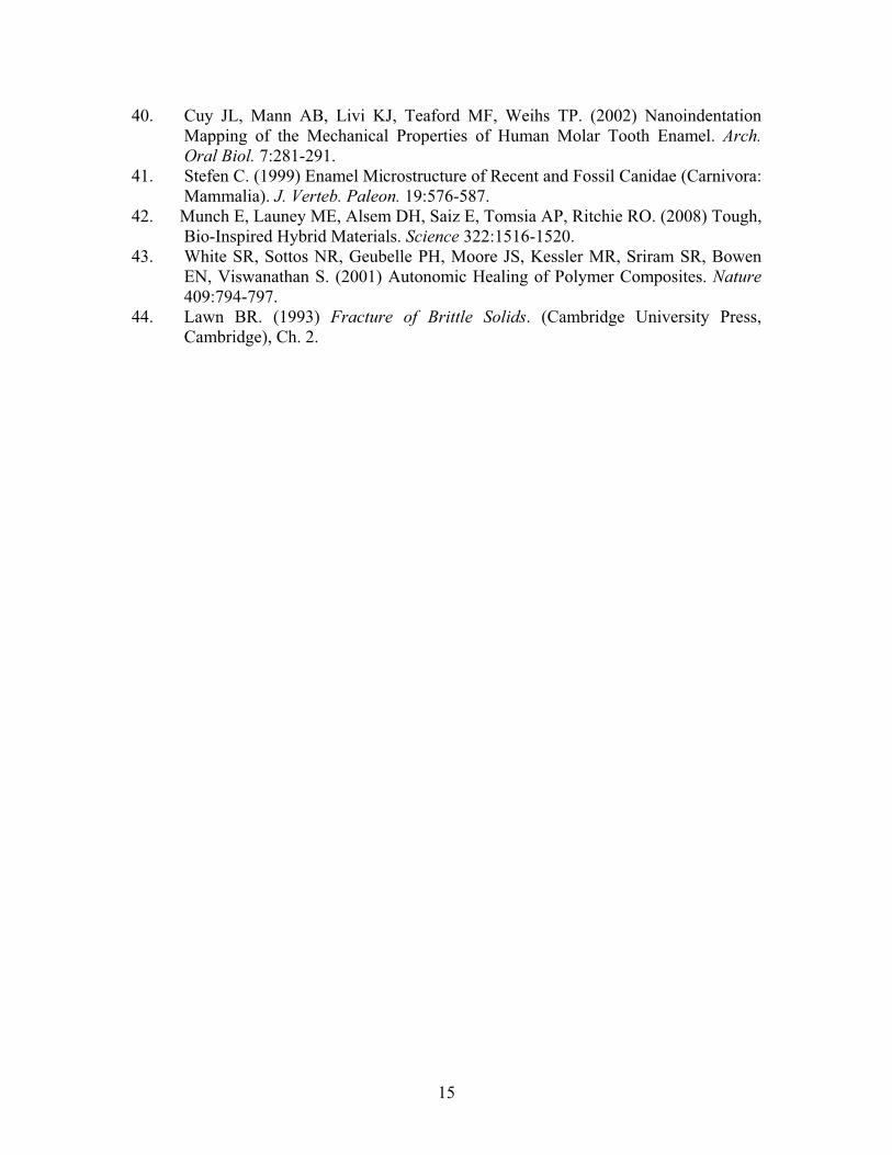
40. Cuy JL, Mann AB, Livi KJ, Teaford MF, Weihs TP. (2002) Nanoindentation Mapping of the Mechanical Properties of Human Molar Tooth Enamel. Arch. Oral Biol. 7:281-291.
41. Stefen C. (1999) Enamel Microstructure of Recent and Fossil Canidae (Carnivora: Mammalia). J. Verteb. Paleon. 19:576-587.
42. Munch E, Launey ME, Alsem DH, Saiz E, Tomsia AP, Ritchie RO. (2008) Tough, Bio-Inspired Hybrid Materials. Science 322:1516-1520.
43. White SR, Sottos NR, Geubelle PH, Moore JS, Kessler MR, Sriram SR, Bowen EN, Viswanathan S. (2001) Autonomic Healing of Polymer Composites. Nature409:794-797.
44. Lawn BR. (1993) Fracture of Brittle Solids. (Cambridge University Press, Cambridge), Ch. 2.
16
Figure Legends
1. Fracture of teeth indented along a vertical axis with the flat end of a WC rod, (A)
human molar, maximum load 390 N, (B) sea otter molar, maximum load 450 N.
Radial–median (R) cracks have propagated part way downward from the contact
zone, margin (M) cracks all the way upward from the cervical base. Some plastic
flattening of the indented cusp is evident immediately beneath the indenter.
2. Optical micrographs showing how cracks grow from tufts at the EDJ in the
vicinity of the vertical load axis, in human molar. Specimen is longitudinal slice
of thickness 1.8 mm, (A) before and (B) after indentation with WC rod (upper
cusp not shown). Cracks in (B) have extended upward from tufts toward the
cuspal surface. The faintly visible fringes (Hunter–Schreger bands) mark changes
in prism orientation.
3. Optical micrographs from longitudinal sections of (A) human and (B) sea otter
molars, showing disruption of cracks at Hunter–Schreger bands. Location of field
of view in (A) is near EDJ, immediately adjacent to the tooth axis; in (B) is some
2 mm below the cusp surface, midway between EDJ and outer enamel surface.
4. FEA calculations of stress intensity factor K as function of reduced crack size c/w,
for extension of periodic array of cracks in curved bilayer slice. Solid curves are
calculations for crack arrays in inhomogeneous contact stress field, with w/d = 0.1
mm/1.8 mm = 0.055. Heavy dashed curve is for single crack in same stress field.
Light dashed curve is for same single crack under uniform stress σ.
17
5. Segment of transverse section view through molars: (A) human, loaded to 450 N
and sectioned to depth 4.4 mm below the cuspal surface; (B) sea otter, loaded to
550 N and sectioned to depth 2.2 mm. Dentin is exposed at top of field of view.
Cracks (arrows) appear to initiate from tufts.
6. Scanning electron micrographs from transverse section of human molar, showing
intersection of Vickers corner crack CC' with (A) tuft TT', showing delamination
at lower tuft interface along C'T and C'T', and (B) margin crack MM', showing
penetration through interface to adjacent enamel.
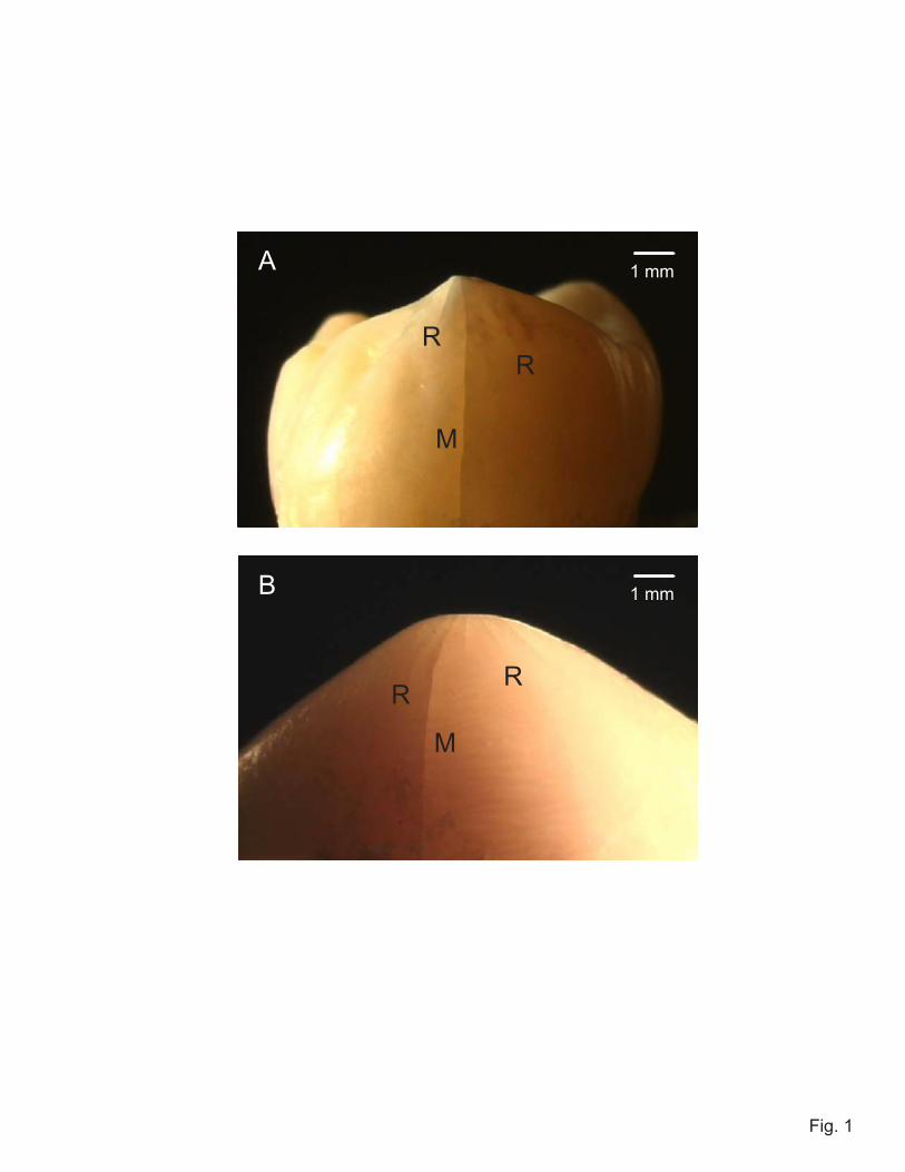
Fig. 1
A
RR
RR
M
M
B
1 mm
1 mm

A
B
Fig. 2
200 μm
Enamel
Enamel
Dentin
Dentin
200 μm
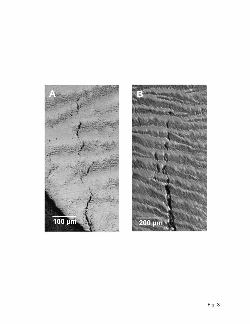
Fig. 3
200 μm
A B
100 μm
w c
d
Cra
ck d
rivin
g fo
rce,
K/
w1/
2
Crack size, c/w
Fig. 4
00
1.5
1.0
0.5
2 4 6
Single center tuft
Tuft 1
2
3
4
Uniform tension
12 23 34 455
1 mm
0.5 mm
Fig. 5
B
1 mm
A
Enamel
Enamel
Dentin
Dentin
C
C
C�
C�
T
T�
M
M�
Fig. 6
5 μm
1 μm
A
B