Embed Size (px)
Citation preview

© Faculty of Mechanical Engineering, Belgrade. All rights reserved FME Transactions (2017) 45, 243-250 243
Received: June 2016, Accepted: November 2016
Correspondence to: Prof. Gunter Weiss
Institute for Geometry, Waidhausenstr. 45, A-1140
Vienna, Austria
E-mail: [email protected]
doi:10.5937/fmet1702243W
G. Weiss
Ret. Professor, Universities of Technology
Dresden and Vienna Institute for Geometry
Austria
H. Ebisui
Priv. Scientist, Oval Research Centre,
Iwakuni Japan
Remarks on Perspective Simplices The planar figure of two triangles being in perspective position is
associated with a theorem of Desargues, which is responsible for the fact
that the coordinate set of the plane is a field. This well-known theorem of
Desargues allows the obvious interpretation in space of a three-sided
pyramid, which is intersected by two planes. The article is dedicated to
generalizing this theorem of Desargues to perspective simplices in a
projective n-space and their linear images in a subspace. Hereby one can
find remarkable incidences and configurations. Starting point to this
investigation is a planar figure of perspective quadrangles, where the
second author discovered a remarkable coincidence figure. The proof of
this incidence statement is based on an interpretation of the planar
“Ebisui figure” as the central projection of a (projective) cross-polytope
in 4-space. This principle can also be extended to higher dimensions.
Keywords: projective space, harmonic homology, Desargues’ theorem,
simplex, cross polytope, polyhedron. (MSC 2000: 51A20, 51M05)
1. INTRODUCTION AND EBISUI’S THEOREM
Let π be a projective Desargues plane such that its
coordinate field F has not the characteristic 2. As a
consequence of these assumptions π can be immerged
into a projective space of dimension n ≥ 3 and there
exist harmonic quadruplets of collinear points. (Plane π
is a Fano plane, i.e. each quadrangle in π has a triangle
of diagonal points; confer e.g. [1].) For such a plane π
the following theorem holds, see also Figure 1.
Theorem 1 (“Ebisui’s Theorem”): Let (Ai, Bi, Ci, Di),
i = 1,2, be two Z-perspective quadrangles of π . Then
the intersection points
1 1 2 2 1 1 2 2
1 1 2 2 1 1 2 2
1 2 2 1 1 2 2 1
: , : ,
: , : ,
: , : ,
A B A B E C D C D E
B C B C F D A D A F
A C A C G B D B D G
∩ = ∩ =
∩ = ∩ =
∩ = ∩ =
(1)
define three lines , ,EE FF GG which are incident with
a common point H.
(This theorem was communicated by the second
author at the „Meeting of the Japan Society for
Geometry and Graphics”, Mai 12-13, 2007, Tokyo.)
A simple but lengthy proof of Theorem 1 might use
elementary affine vector calculus in π assuming that
none of the given and calculated points is an ideal point.
Of course one will use an affine (or even projective)
coordinate frame in π, which is suitably connected with
the given point set Z, Ai, ..., Di to make calculation as
simple as possible. But such an analytic proof does not
show, where Theorem 1 belongs to and in which way it
generalises the well-known Desargues’ theorem of
perspective triangles. As the Theorem 1 deals only with
incidences, it obviously belongs to projective geometry
based on a rather general coordinate field F , even it, at
first, was stated as a theorem in a Euclidean plane.
Figure 1. Two perspective quadrangles lead to an “opposite” point H of the perspectivity centre Z.
Note that the points ,G G stem from “overcrossing”
pairs of corresponding points of the two sets A1,..., D1
and A2,..., D2 and that the Desargues axes of the four
pairs of triangles (A1B1C1, A2B2C2), (B1C1D1, B2C2D2),
(C1D1A1, C2D2A2), and (D1A1B1, D2A2B2) form a complete
quadrilateral with the six vertices , ,EE FF GG !
In the following we interpret the planar figure to
Theorem 1 as an image of an object in space, similar to
the classical interpretation of the (planar) Theorem of
Desargues as linear image of a triangular pyramid,
which is intersected by two planes. This allows a proof
of Theorem 1 by simple reasoning instead of calculation
and it gives a hint, how to generalize it to higher (and
even lower) dimensions:
We interpret the planar “Ebisui figure” as the central
projection of a cross-polytope in 4-space. Even so one at
first might start with a regular cross-polytope in the
Euclidean 4-space, the proof holds also for 4-spaces
over any field F with char F ≠ 2. Using this idea
allows to interpret any (classical) Desargues figure as

244 VOL. 45, No 2, 2017 FME Transactions
the central projection of a regular octahedron in the
projective enclosed Euclidean 3-space. Similarly, as any
quadrangle Q can be interpreted as central projection of
a square Q’, the quadrangle Q together with its 6 lines,
i.e. the ‘complete’ quadrangle, can be interpreted as the
2-dimensional case of an Ebisui figure.
For dimensions n > 4 there exist incidence figures,
too, but we end up with rather complicated con-
figurations. Anyway, higher dimensional interpretations
of perspective simplices and their connection to cross-
polytopes still are possible and will result in incidence
statements for those cross-polytopes.
2. DESARGUES’ THEOREM AND CENTRAL
AXONOMETRY
The well-known theorem of Desargues concerns two Z-
perspective triangles and deals with incidences alone. If
the place of action is a projective plane π such that
Desargues’ theorem is valid, then π is embeddable into a
projective 3-space Π, and the Desargues theorem
becomes obvious by the well-known interpretation of
the figure as the linear image of an object in Π, namely
of a 3-sided pyramid intersected by two planes, see
Figure 2.
Figure 2. (a) general case of a (labelled) Desargues figure (left) (b) interpretation of (a) as image of an object in 3-space, which defines a perspectivity Ψ and a harmonic homology y.
If the Desargues axis z of a (labelled) Desargues
figure (see Figure 2(a)) does not pass through the pers–
pectivity centre Z, this figure defines a homology κ:π → π
with centre Z, axis z and a pair (A1, A2) of corresponding
points. The cross ratio ( )2 1, , , :CR A A Z z c== ∈F is
called the “characteristic cross ratio” of κ.
The Desargues figure shows an elation κ:π → π, if
Z z∈ . In this case a characteristic cross ratio is not
defined.
Remark: We distinguish the concepts “Desargues
figure” and “Desargues configuration”. The (103, 103) -
configuration of Desargues (Figure 2a) is a set of 10
points and 10 lines and no point (line) is distinguished
from any other point (line). The concept characteristic
cross-ratio does not make sense for such an “un-
labelled” configuration. Taking another point of this
configuration as center Z leads (in general) to another
characteristic cross ratio value. The relation of all
possible characteristic cross ratios to a Desargues
configuration is described in [6].
In the 3-space Π the pre-image of the planar
homology or elation κ is a perspectivity ψ:π1 → π2 of a
plane π1 onto a plane π2 with the pyramid’s vertex V as
the perspectivity centre, see Figure 2(b). This
perspectivity ψ can be embedded into perspective
collineations χ:Π → Π and there is a one-parametric set
of such collineations, as we may choose any plane ω
through π1 ∩ π2 as fixed plane. Among these colline–
ations χ, for any coordinate field
( )2 1, , , :CR A A Z z c== ∈F of char F ≠ 2, besides the
two singular ones with ω = π1 or ω = π2 as axis, there are
two canonically distinguished regular ones: the elation χ0
with the fixed plane (π1 ∩ π2) ˅ V ==: ω and the harmonic
homology χ-1 with an axis ω such that CR(π2, π1, z ˅ Z,
ω) = -1. (We supposed π to be a Fano plane, therefore
harmonic homologies in π and in Π are well defined
regular perspective collineations.)
As we finally aim at the “overcrossings” occurring
in Theorem 1 it seems to be natural to consider only the
harmonic homology χ-1 as the distinguished collineation
within the set of all perspective collineations belonging
to ψ.
Let us at first consider a classical Desargues figure
in a projective plane π which we at first embed into a
projective enclosed affine 3-space Πα. The basic figure
of two Z-perspective triangles Z; A1, B1, C1; A2, B2, C2)
⊂ π can be interpreted as the fundamental figure of a
central axonometry α: Πα → π.
Remark: „central axonometry“ means a linear mapping
of a space Π onto an image plane π based on a
projective coordinate frame in Π and its linear image
figure, which usually is called the “axonometric
fundamental figure”, (see e.g. [2], [3], [4] and [5]).
Extensions to higher dimensions are obvious.
Figure 3. An axonometric fundamental figure connected with a Desargues figure.
Thereby Z =: Oα is the image of the origin O in
space, furthermore we use A1, B1, C1 as the images of
“unit points” 1 1 1
1 1 1, ,R A S B T Cα α α− − −
= = = , and
interpret A2, B2, C2 as the images of “ideal points” 1 1 1
2 2 2, ,U A V B W Cα α α− − −
= = = of the “coordinate
axes” u, v, w ⊂ Π through O, see Figure 3.
The “unit plane” ε = RST intersects the “ideal plane”
v = UVW in the pre-image of the Desargues axis z of the
two Z-perspective triangles. Thus the fixed plane of
the harmonic homology χ-1 intersects u, v, w in the
“negative unit points” R-, S- and T-.
Remark: As we are free in choosing Πα and its ideal
elements, we could have started with a projective space
Π and an axonometry such that R-, S
-, T- become the
pre-images of A2, B2, C2. Then the fixed plane ω of the
above mentioned harmonic homology χ-1 automatically
acts as the “ideal plane”. Furthermore, if we assume that
FME Transactions VOL. 45, No 2, 2017 245
F is a Euclidean field, then (Π, ω) allows an
interpretation as a projective enclosed Euclidean space
and R, S, T, R-, S-, T- become the vertices of a regular
octahedron with centre O. We collect this as:
Theorem 2: Let π be a projective plane over the
field ≈ ℝF and A1, B1, C1 and A2, B2, C2 two Z-
perspective triangles in π. Then Z; A1, B1, C1; A2, B2,
C2 ⊂ π can always be interpreted as the central
axonometric image of midpoint and vertices of a
(Euclidean) regular octahedron.
3. THEOREM 1 AND CENTRAL AXONOMETRY
Let us now turn back to the planar configuration of two
Z-perspective quadrangles (Ai,..., Di), i = 1, 2 as
described in Theorem 1. Analog to Theorem 2 we now
interpret this labelled configuration as the central
axonometric image of an affine regular cross-polytope
P8 in the projectively extended four-dimensional affine
space 4αΠ over the field F .
Again we interpret the two Z-perspective planar
quadrangles at first as linear images of two O-perspective
tetrahedra, each spanning a hyperplane Π1 resp. 4
2 αΠ ⊂ Π . We now embed the O-perspectivity ψ:Π1 →
Π2 into a harmonic homology 4 4: α αχ Π ⊂ Π with centre
O (the pre-image of Z) and with a certain hyperplane Ω as
the fixed axis of χ. Let us choose Ω as the ideal
hyperplane of 4αΠ such that O is a proper point of
4αΠ .
Then, by using the originals O and 41 1,...,A D α′ ′∈Π of Z,
A1,..., D1∈π as origin and unit points of a coordinate
frame, we receive very simple projective coordinates of
the points of the entire configuration, namely:
( ) ( )
( ) ( )
( )
1, 1,0,0,0 , 1,0, 1,0,0 ,
1,0,0, 1,0 , 1,0,0,0, 1 ,
1,0,0,0,0 , 1, 2.
i i
i i
A B
C D
Z i
′ ′= ± = ±
′ ′= ± = ±
′ = =
F F
F F
F
(2)
Therewith we get the originals (c.f. (1)) , ,E E′ ′ ,F ′
, ,F G G′ ′ ′ of ,...,E G almost without any calculation as:
( ) ( )
( ) ( )
( ) ( )
0,1, 1,0,0 , 0,0,0,1, 1 ,
0,0, 1,1,0 , 0,1,0,0, 1 ,
0,1,0,1,0 , 0,0,1,0,1 ,
E E
F F
G G
′ ′= − = −
′ ′= − = −
′ ′= =
F F
F F
F F
(3)
and finally
( ) ( )( ) ( ) ( )( ) ( ) ( )( )
( ) ( ) ( ) ( )2
0,1, 1,0,0 0,1, 1,0,0 ,
0,1,0,0, 1 0,0,1, 1,0 ,
0,1,0,1,0 0,0,1,0,1 ,
, , , , , \ 0,0
E E
F F
G G v
v v
λ λ
µ µ
ν
λ λ µ µ
′ ′ = − + −
′ ′ = − + −
′ ′ = +
⊂
F
F
F
F
(4)
These three lines (4) intersect in a common point:
( ): 0,1, 1,1, 1E E F F G G H′ ′ ′ ′ ′ ′ ′∩ ∩ = = − − F (5)
As the three lines , , , , ,E E F F G G′ ′ ′ ′ ′ ′ of 4αΩ ⊂ Π
indeed coincide with a common point H', any linear
image of them must have the same property, i.e. the α-
images , ,EE FF GG of these lines are concurrent with a
point H = H'α. Therewith we have proved
Theorem 3: Let be given a labelled planar “Ebisui
figure” consisting of two Z-perspective quadrangles (Ai,
Bi, Ci, Di), i = 1,2 together with centre Z and the
intersection points ,...,E G according to Theorem 1.
- Then Z; A1,.., D1; A2,..., D2 can always be interpreted
as the linear image (central axonometric image) of an
affine regular cross-polytope P8 with vertices A'1,...,
D'2 and centre Z' in a four-dimensional projective
extended affine space 4αΠ .
- Furthermore, the originals , ,E F G′ ′ ′ and , ,E F G′ ′ ′ of
,...,E G form two perspective triangles in the ideal
hyperplane Ω of 4αΠ with a point H' as their Desargues
centre, which maps onto the remarkable “Ebisui-point”
H of the given Ebisui figure.
Remark 1: Obviously, if 4αΠ is taken as a projective
enclosed Euclidean 4-space, then P8 can be interpreted
as a Euclidean regular cross-polytope.
Remark 2: Note that central axonometry maps a point P'
of the n-space to a point P of an image k-space or plane
using the so-called coordinate path with respect to the
axonometric base figure. The coordinate path uses the
projective coordinates of P', therefore it is not necessary
to distinguish between the original P' and their
axonometric image P in terms of coordinates. In the
following we therefore will omit to use different
labelling for originals and their images, as it will come
clear from the text what is meant.
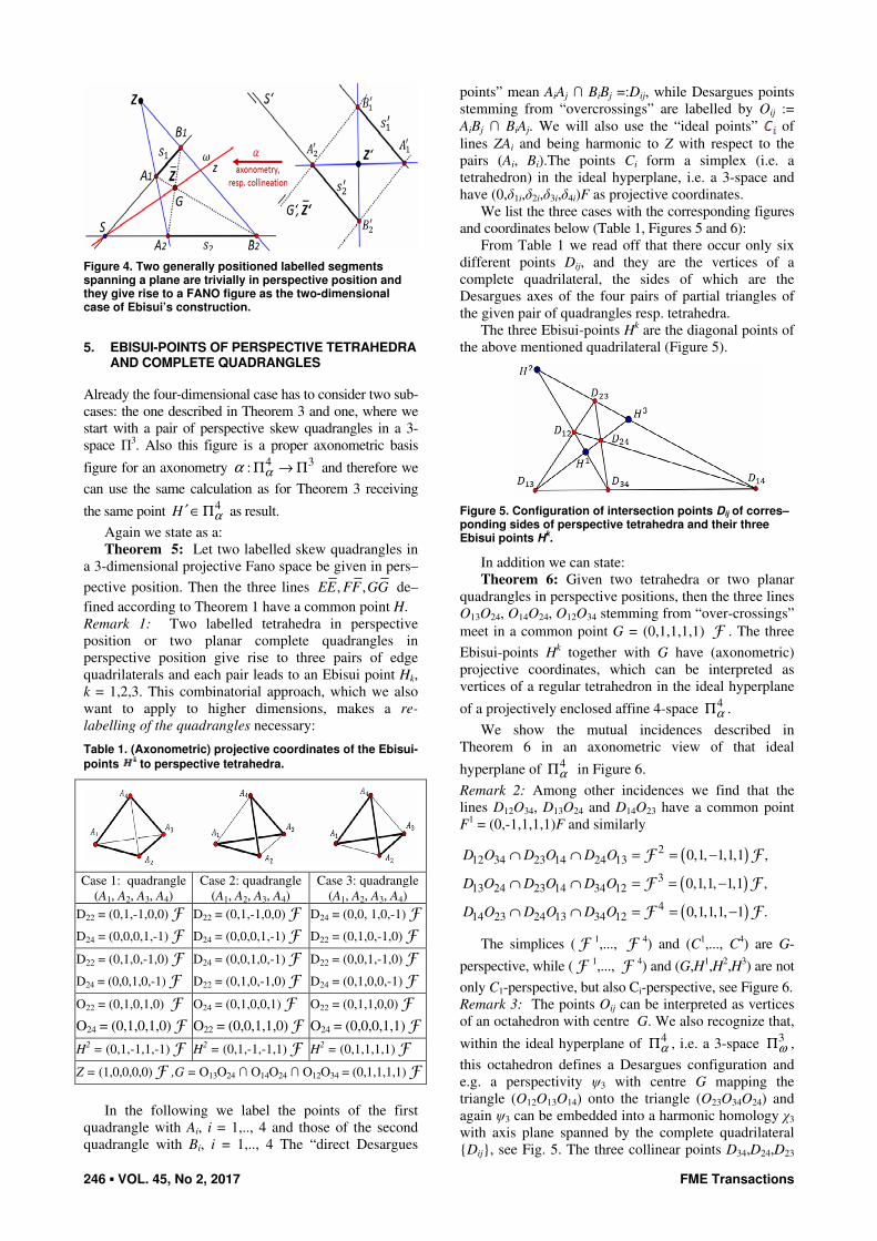
4. COMPLETE QUADRANGLES AS THE TWO-
DIMENSIONAL CASE: FANO’S FIGURE
Instead of perspective triangles in a projective Fano-plane
π and its interpretation as (central) axonometric image of
an octahedron let us now consider two line segments s1:=
(A1, B1) s2:= (A2, B2) ⊂ π such that the endpoints of those
segments form a quadrangle. These labelled segments
define a unique perspectivity centre Z (see Fig. 4). Inter–
pretation in space now degenerates to an interpretation in
a projective enclosed affine (resp. Euclidean) plane π':
(A1,..., B2) are linear axonometric images of the vertices
(A'1,..., B'2) of a parallelogram (resp. a square); thereby
point Z is the image of its centre Z'.
Again we embed the perspectivity ψ:s'1 → s'2 into a
harmonic homology χ:s'1 → s'2 and its axis passes
through point S':= A'1B'1 ∩ A'2B'2 and it contains the
intersection G' of “overcrossing lines” A'1B'2, A'2B'1.The
axonometry α:π' → π is simply a projective colli–
neation, we receive CR(A1B1, A2B2, Z, z), what is a tri–
vial property of complete quadrangles in a Fano plane π.
As a trivial result we state:
Theorem 4: A labelled complete quadrangle in a
projective Fano plane allows an interpretation as the
two-dimensional (degenerated) case of a general
Desargues figure in the sense of H. Ebisui.
246 VOL. 45, No 2, 2017 FME Transactions
Figure 4. Two generally positioned labelled segments spanning a plane are trivially in perspective position and they give rise to a FANO figure as the two-dimensional case of Ebisui’s construction.
5. EBISUI-POINTS OF PERSPECTIVE TETRAHEDRA
AND COMPLETE QUADRANGLES
Already the four-dimensional case has to consider two sub-
cases: the one described in Theorem 3 and one, where we
start with a pair of perspective skew quadrangles in a 3-
space Π3. Also this figure is a proper axonometric basis
figure for an axonometry 4 3: αα Π → Π and therefore we
can use the same calculation as for Theorem 3 receiving
the same point 4H α′∈ Π as result.
Again we state as a:
Theorem 5: Let two labelled skew quadrangles in
a 3-dimensional projective Fano space be given in pers–
pective position. Then the three lines , ,EE FF GG de–
fined according to Theorem 1 have a common point H.
Remark 1: Two labelled tetrahedra in perspective
position or two planar complete quadrangles in
perspective position give rise to three pairs of edge
quadrilaterals and each pair leads to an Ebisui point Hk,
k = 1,2,3. This combinatorial approach, which we also
want to apply to higher dimensions, makes a re-
labelling of the quadrangles necessary:
Table 1. (Axonometric) projective coordinates of the Ebisui-
points to perspective tetrahedra.
Case 1: quadrangle
(A1, A2, A3, A4)
Case 2: quadrangle
(A1, A2, A3, A4)
Case 3: quadrangle
(A1, A2, A3, A4)
D22 = (0,1,-1,0,0) F
D24 = (0,0,0,1,-1) F
D22 = (0,1,-1,0,0) F
D24 = (0,0,0,1,-1) F
D24 = (0,0, 1,0,-1) F
D22 = (0,1,0,-1,0) F
D22 = (0,1,0,-1,0) F
D24 = (0,0,1,0,-1) F
D24 = (0,0,1,0,-1) F
D22 = (0,1,0,-1,0) F
D22 = (0,0,1,-1,0) F
D24 = (0,1,0,0,-1) F
O22 = (0,1,0,1,0) F
O24 = (0,1,0,1,0) F
O24 = (0,1,0,0,1) F
O22 = (0,0,1,1,0) F
O22 = (0,1,1,0,0) F
O24 = (0,0,0,1,1) F
H2 = (0,1,-1,1,-1) F H2 = (0,1,-1,-1,1) F H2 = (0,1,1,1,1) F
Z = (1,0,0,0,0) F ,G = O13O24 ∩ O14O24 ∩ O12O34 = (0,1,1,1,1) F
In the following we label the points of the first
quadrangle with Ai, i = 1,.., 4 and those of the second
quadrangle with Bi, i = 1,.., 4 The “direct Desargues
points” mean AiAj ∩ BiBj =:Dij, while Desargues points
stemming from “overcrossings” are labelled by Oij :=
AiBj ∩ BiAj. We will also use the “ideal points” of
lines ZAi and being harmonic to Z with respect to the
pairs (Ai, Bi).The points Ci form a simplex (i.e. a
tetrahedron) in the ideal hyperplane, i.e. a 3-space and
have (0,δ1i,δ2i,δ3i,δ4i)F as projective coordinates.
We list the three cases with the corresponding figures
and coordinates below (Table 1, Figures 5 and 6):
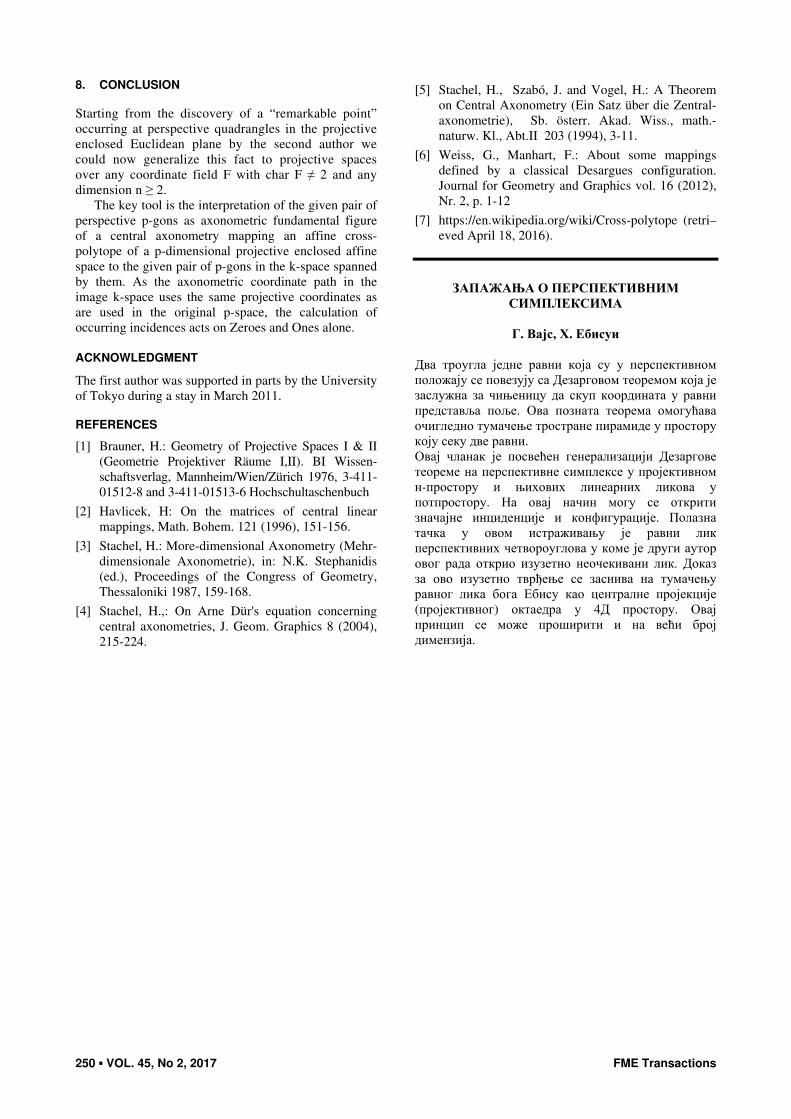
From Table 1 we read off that there occur only six
different points Dij, and they are the vertices of a
complete quadrilateral, the sides of which are the
Desargues axes of the four pairs of partial triangles of
the given pair of quadrangles resp. tetrahedra.
The three Ebisui-points Hk are the diagonal points of
the above mentioned quadrilateral (Figure 5).
Figure 5. Configuration of intersection points Dij of corres–ponding sides of perspective tetrahedra and their three Ebisui points H
k.
In addition we can state:
Theorem 6: Given two tetrahedra or two planar
quadrangles in perspective positions, then the three lines
O13O24, O14O24, O12O34 stemming from “over-crossings”
meet in a common point G = (0,1,1,1,1) F . The three
Ebisui-points Hk together with G have (axonometric)
projective coordinates, which can be interpreted as
vertices of a regular tetrahedron in the ideal hyperplane
of a projectively enclosed affine 4-space 4αΠ .
We show the mutual incidences described in
Theorem 6 in an axonometric view of that ideal
hyperplane of 4αΠ in Figure 6.
Remark 2: Among other incidences we find that the
lines D12O34, D13O24 and D14O23 have a common point
F1 = (0,-1,1,1,1)F and similarly
( )
( )
( )
212 34 23 14 24 13
313 24 23 14 34 12
414 23 24 13 34 12
0,1, 1,1,1 ,
0,1,1, 1,1 ,
0,1,1,1, 1 .
D O D O D O
D O D O D O
D O D O D O
∩ ∩ = = −
∩ ∩ = = −
∩ ∩ = = −
F F
F F
F F
The simplices ( F 1,..., F 4) and (C1,..., C4) are G-
perspective, while ( F 1,..., F 4) and (G,H1,H2,H3) are not
only C1-perspective, but also Ci-perspective, see Figure 6.
Remark 3: The points Oij can be interpreted as vertices
of an octahedron with centre G. We also recognize that,
within the ideal hyperplane of 4αΠ , i.e. a 3-space
3ωΠ ,
this octahedron defines a Desargues configuration and
e.g. a perspectivity ψ3 with centre G mapping the
triangle (O12O13O14) onto the triangle (O23O34O24) and
again ψ3 can be embedded into a harmonic homology χ3
with axis plane spanned by the complete quadrilateral
Dij, see Fig. 5. The three collinear points D34,D24,D23

FME Transactions VOL. 45, No 2, 2017 247
span the Desargues axis of the perspectivity ψ3, i.e. the
lines O12O13 and O34O24 meet at D23, and so on. But
there are altogether four possibilities of such
perspectivities resp. homologies and each side of the
complete quadrilateral Dij acts as Desargues axis of
each of these perspectivities.
Figure 6. Configuration of intersection points Oij of “over–crossing” connecting sides of perspective tetrahedra and their three Ebisui points H
k.
Our cross-polytope P8, which realises a per-
spectivity ψ4 between two opposite face tetrahedra and
the canonically defined harmonic homology χ4 to ψ4,
induces an octahedron P6 in the (ideal) axis hyperplane
of χ4. This octahedron again delivers the classical
situation of a Desargues figure as treated in Chapter 2
with the two-dimensional case of a complete quadrangle
in the axis plane of χ3, see Chapter 4. In the following
we shall see that this hierarchical structure also holds
for higher-dimensional cases.
6. HIGHER-DIMENSIONAL CASES
The idea of interpreting the planar figures as
axonometric image of a square, an octahedron or a
cross-polytope P8 suggests to consider pairs of closed
polygons with p vertices in perspective position in a
given classical projective k-space Πk and interpret them
as the central axonometric image of a cross-polytope P2p
in an n-dimensional affine (resp. Euclidean) space pαΠ
with an “ideal hyperplane” 1pω
−Π as projective
enclosure. The polygons (A1,..., Ap) and (B1,..., Bp)
together with centre Z give reason to 4
p
quadrangles
and each of them lead to three Ebisui-points and one
point G. There occur 2
p
direct Desargues points Dij =
AiAj ∩ BiBj and 2
p
points Oij stemming from
“overcrossing” lines AiBj, AjBi. Interpreting the points of
the two polygons as vertices of P2p with centre Z (- we
use the same symbols for points in Πk and in pαΠ - ) the
points Dij and Oij as well as the Ebisui-points and the
points of type span the ideal hyperplane 1pω
−Π . The
intersections of 1pω
−Π ∩ ZAi =:Ci can be used to
define a coordinate frame in 1pω
−Π . The three hyper–
planes 1pω
−Π , 1p
A−
Π , 1p
B−
Π , spanned by Ci. Ai
resp. Bi intersect in a space 2pω
−Π spanned by the set
Dij, see Figure 7.
In the following we present only the case p = 5 as an
example. It illustrates already the occuring incidences
and configurations also for arbitrary cases of p:
Let two Z-perspective 5-gons Ai,Bi ≠ Ai be given
in a projective k-space (2 ≤ k ≤ 5), then, after
interpreting this set of 11 points (which we assume to be
different) as an axonometric fundamental figure of an
axonometry α:Π5 → Πk, the originals Z resp. Ai resp. Bi
the homogenous coordinates (1,0,0,0,0) F resp.
(1,δ1i,..., δ5i) and (1,-δ1i, -δ2i, -δ3i, -δ4i, -δ5i,) form a 5-
cross-polytope P10. By this we get 10 “direct” and 10
“overcrossing” Desargues points as follows (Table 2):
Figure 7. Symbolic visualisation of perspective p-simplexes and their “direct” and “overcrossing” Desargues points Dij and Oij.
Table 2. : (Axonometric) projective coordinates of the direct and overcrossing Desargues points to perspective 5-gons
D12 = A1A2 ∩ B1B2 =
= (0,1,-1,0,0,0) F
O12 = A1B2 ∩ B1A2 =
= (0,1,1,0,0,0) F
D22 = A2A2 ∩ B2B2 =
= (0,1,0,-1,0,0) F
O22 = A2B2 ∩ B2A2 =
= (0,1,0,1,0,0) F
D14 = A1A4 ∩ B1B4 =
= (0,1,0,0,-1,0) F
O14 = A1B4 ∩ B1A4 =
= (0,1,0,0,1,0) F
D15 = A1A5 ∩ B1B5 =
= (0,1,0,0,0,-1) F
O15 = A1B5 ∩ B1A5 =
= (0,1,0,0,0,1) F
D22 = A2A2 ∩ B2B2 =
= (0, 0, 1,-1,0,0,) F
O22 = A2B2 ∩ B2A2 =
= (0,1,1,0,0,0) F
D24 = A2A4 ∩ B2B4 =
= (0,1,0,0,-1,0) F
O24 = A2B4 ∩ B4A2 =
= (0,0,1,0,1,0) F
D23 = A2A3 ∩ B2B3 =
= (0,0,1,0,0,-1) F
O23 = A2B3 ∩ B3A2 =
= (0,0,1,0,0,1) F
D24 = A2A4 ∩ B2B4 =
= (0,0,0,1,-1,0) F
O24 = A2B4 ∩ B4A2 =
= (0,0,0,1,1,0) F
D25 = A2A5 ∩ B2B5 =
= (0,0,0,1,0,-1) F
O25 = A2B5 ∩ B5A2 =
= (0,0,0,1,0,1) F
D45 = A4A5 ∩ B4B5 =
= (0,0,0,0,1,-1) F
O45 = A4B5 ∩ B5A4 =
= (0,0,0,0,1,1) F

248 VOL. 45, No 2, 2017 FME Transactions
From Table 2 follows that the ten triplets of direct
Desargues points (Dij, Djk, Dik) are collinear with lines dijk
and that all those points Dij span a 3-space 3 4 5ω ω ωΠ ⊂ Π ⊂ Π . As expected we find that the 10 points
Dij and 10 lines dijk form a Desargues configuration in 3ωΠ with five planes m
Qω , m = 1, ..., 5, () (m ≠ i ≠ j ≠ k ≠
l), containing 4 lines dijk and six points Dij. These five
planes correlate to the five Z-perspective pairs of partial
quadrangles mAQ = AiAjAkAl,
mAQ = BiBjBkBl of the given
perspective 5-gons, and each of the pairs ( ),m mA BQ Q leads
to a triplet of Ebisui points ( )1 2 3, ,m m mH H H in the
corresponding plane 3 3Qω ω⊂ Π and a point
4mG ω∈ Π .
We list the coordinates in Table 3:
Table 3. : (Axonometric) projective coordinates of the direct and overcrossing Desargues points to perspective 5-gons
( )3 3,A BQ Q 32
0
1
1
1
1
0
H
−
= −
F 3
2
0
1
1
1
1
0
H
−
= −
F 3
2
0
1
1
1
1
0
H
= − −
F 3
0
1
1
1
1
0
G
=
F
( )2 2,A BQ Q 42
0
1
1
0
1
1
H
−
= −
F 42
0
1
1
1
0
1
H
−
= −
F 42
0
1
1
1
0
1
H
= − −
F 4
0
1
1
1
0
1
G
=
F
( )4 4,A BQ Q 22
0
1
1
0
1
1
H
−
= −
F 22
0
1
1
0
1
1
H
−
= −
F 22
0
1
1
1
1
0
H
= − −
F 2
0
1
1
0
1
1
G
=
F
( )2 2,A BQ Q 22
0
1
0
1
1
1
H
= − −
F 22
0
1
0
1
1
1
H
= − −
F 22
0
1
0
1
1
1
H
= − −
F 2
0
1
0
1
1
1
G
=
F
( )1 1,A BQ Q 21
0
0
1
1
1
1
H
= − −
F 21
0
0
1
1
1
1
H
= − −
F 21
0
0
1
1
1
1
H
= − −
F 1
0
0
1
1
1
1
G
=
F
From Tables 2 and 3 we read off that the ten lines
GmG
l pass through Dmi and that e.g. H5, O12, O34, G
5 are
collinear and harmonic, and we notice that e.g. the pair
of Ebisui triangles ( )5 5 51 2 3H H H and ( )2 2 2
1 2 3H H H is D34-
perspective. The “ideal points” 4
iC ω∈ Π of the five
lines AiBi are harmonic to Z = (1,0,..., 0)F with respect
to (AiBi) and they are therefore well defined also in the
axonometric image space Πk, 2 ≤ k < 5.
The five pairs of points (Ci,Gi) are in perspective
position with the “unit point” G = (0,1,1,1,1,1) F
4ω∈ Π . The quadruplets (D12,D13,D14,D15) and (O12,O13,
O14,O15) are C1-perspective and form a 4-cross-polytope
P8 with centre C1 and “ideal points” (C2,C3,C4,C5) as
expected.
Obviously there occur all together five such 4-
crosspolytopes and the points Ci are their centres. The
tetrahedron (C2,C3,C4,C5) contains the octahedron (O23,
O24,O34,O35,O45) as a cross-polytope P6 with centre G1,
see Figure 8.
Figure 8. One of the five partial octahedra within the set of 10 “overcrossing” Desargues points Oij.
These statements concerning incidences and
relations occurring in a special-dimensional case should
give sufficient insight into the combinatorial and
analytic methods to treat also arbitrary dimensional
cases. The occurrence of Desargues configurations and
their higher dimensional analogues shall be mentioned
in more detail in the next chapter.
7. GENERALIZED DESARGUES CONFIGURATIONS AND CROSS-POLYTOPES
In the former Chapters we found complete quadri–
laterals (resp. quadrangles) and 3D-Desargues configu–
ration connected with cross-polytopes. For such cross-
polytopes one can present a list of facets in Table 4 (at
the end of text), see also [7].
Each face-triangle or face-tetrahedron, together with
“ideal” points and lines, gives rise to a complete face-
quadrilateral resp. a Desargues configuration in the
projective extended 3-space spanned by the face-
tetrahedron.
Similarly, a k-face-simplex, together with its ideal
elements, defines what might be called a “i- Desargues
configuration” generalizing the standard case to higher
dimensions. Also here the system of incidences shall be
shown in a Table 5 (also at the end of text).

FME Transactions VOL. 45, No 2, 2017 249
Table 4. Numbers of k-facets of a cross-polytope P2n
dim name points lines 2-facets 3-facets 4-facets 5-facets 6-facets n--1
1 segment 2 1
2 quadrangle 4 4 1
3 octahedron 6 12 8 1
4 16-cell 8 24 32 16 1
5 Pentacross 10 40 80 80 32 1
6 Hexacross 12 60 160 240 192 64 1
7 Heptacross 14 84 280 560 672 448 128 1
⋮ ⋮ ⋮ ⋮ ⋮
n n-Cross points
2n
lines
43
n
planes
84
n
k-facets:
12 ,1
k nk n
k
+ <
+
(n-1)-
facets:
2n
Table 5. Numbers of incident subspaces within -dimensional generalized Desargues configurations
dim incident
with a
points lines planes 3-spaces 4-spaces 5-spaces 6-spaces
point 1 2 1
line 3 1 1 2
plane 6 4 1
point 1 3 3 1
line 3 1 2 1
plane 6 4 1 1 3
3-space 10 10 5 1
point 1 4 6 4 1
line 3 1 3 3 1
plane 6 4 1 2 1
3-space 10 10 5 1 1
4
4-space 15 20 15 6 1
point 1 5 10 10 5 1
line 3 1 4 6 4 1
plane 6 4 1 3 3 1
3-space 10 10 5 1 2 1
4-space 15 20 15 6 1 1
5
5-space 21 35 35 21 7 1
point 1 6 15 20 15 6 1
line 3 1 5 10 10 5 1
plane 6 4 1 4 6 4 1
3-space 10 10 5 1 3 3 1
4-space 15 20 15 6 1 2 1
5-space 21 35 35 21 7 1 1
6
6-space 28 56 70 56 28 8 1
point 1 , ...dimn
k subspacesk
line 3 1 1n
k
−
plane 6 4 1 2n
k
−
3-space 10 10 5 1 3n
k
−
⋮ 2 ...dim
,...dim
p p subspace
k k subspaces
+
1 ...dim
,...dim
n p p subspace
k k subspaces
−
(n-1)-space 1n
k
+
1 1
n
n-space 2n
k
+
1
250 VOL. 45, No 2, 2017 FME Transactions
8. CONCLUSION
Starting from the discovery of a “remarkable point”
occurring at perspective quadrangles in the projective
enclosed Euclidean plane by the second author we
could now generalize this fact to projective spaces
over any coordinate field F with char F ≠ 2 and any
dimension n ≥ 2.
The key tool is the interpretation of the given pair of
perspective p-gons as axonometric fundamental figure
of a central axonometry mapping an affine cross-
polytope of a p-dimensional projective enclosed affine
space to the given pair of p-gons in the k-space spanned
by them. As the axonometric coordinate path in the
image k-space uses the same projective coordinates as
are used in the original p-space, the calculation of
occurring incidences acts on Zeroes and Ones alone.
ACKNOWLEDGMENT
The first author was supported in parts by the University
of Tokyo during a stay in March 2011.
REFERENCES
[1] Brauner, H.: Geometry of Projective Spaces I & II
(Geometrie Projektiver Räume I,II). BI Wissen-
schaftsverlag, Mannheim/Wien/Zürich 1976, 3-411-
01512-8 and 3-411-01513-6 Hochschultaschenbuch
[2] Havlicek, H: On the matrices of central linear
mappings, Math. Bohem. 121 (1996), 151-156.
[3] Stachel, H.: More-dimensional Axonometry (Mehr-
dimensionale Axonometrie), in: N.K. Stephanidis
(ed.), Proceedings of the Congress of Geometry,
Thessaloniki 1987, 159-168.
[4] Stachel, H.,: On Arne Dür's equation concerning
central axonometries, J. Geom. Graphics 8 (2004),
215-224.
[5] Stachel, H., Szabó, J. and Vogel, H.: A Theorem
on Central Axonometry (Ein Satz über die Zentral-
axonometrie), Sb. österr. Akad. Wiss., math.-
naturw. Kl., Abt.II 203 (1994), 3-11.
[6] Weiss, G., Manhart, F.: About some mappings
defined by a classical Desargues configuration.
Journal for Geometry and Graphics vol. 16 (2012),
Nr. 2, p. 1-12
[7] https://en.wikipedia.org/wiki/Cross-polytope (retri–
eved April 18, 2016).
ЗАПАЖАЊА О ПЕРСПЕКТИВНИМ
СИМПЛЕКСИМА
Г. Вајс, Х. Ебисуи
Два троугла једне равни која су у перспективном
положају се повезују са Дезарговом теоремом која је
заслужна за чињеницу да скуп координата у равни
представља поље. Ова позната теорема омогућава
очигледно тумачење тростране пирамиде у простору
коју секу две равни.
Овај чланак је посвећен генерализацији Дезаргове
теореме на перспективне симплексе у пројективном
н-простору и њихових линеарних ликова у
потпростору. На овај начин могу се открити
значајне инциденције и конфигурације. Полазна
тачка у овом истраживању је равни лик
перспективних четвороуглова у коме је други аутор
овог рада открио изузетно неочекивани лик. Доказ
за ово изузетно тврђење се заснива на тумачењу
равног лика бога Ебису као централне пројекције
(пројективног) октаедра у 4Д простору. Овај
принцип се може проширити и на већи број
димензија.


![arXiv:1704.07299v4 [math.CO] 14 Feb 2018(1) There are infinitely many lattice empty 4-simplices of width 1 (e.g., cones overemptytetrahedra)andofwidth2 [10,16]. (2) Among the simplices](https://img.pdfslide.net/doc/110x75/608ea0079eea0f605e46bc64/arxiv170407299v4-mathco-14-feb-2018-1-there-are-ininitely-many-lattice.jpg)