Embed Size (px)
Citation preview

Remediation Method Statement
TCE Monitoring Area, AWE Burghfield, Berkshire
AWE plc
Prepared by: Authorised by: Simon Johnson Robert Jones Park House Greyfriars Road Cardiff CF10 3AF Tel 02920 668 662 JER3996/TCE/RMS Fax 02920 668 622 Revision: 2 Email [email protected] May 2009
Planning & Development
This report has been produced by RPS within the terms of the contract with the client and taking account of the resources devoted to it by agreement with the client.
We disclaim any responsibility to the client and others in respect of any matters outside the scope of the above.
This report is confidential to the client and we accept no responsibility of whatsoever nature to third parties to whom this report, or any part thereof, is made known. Any such party relies on the report at their own risk
RPS Planning and Development Ltd. Registered in England No. 02947164 Centurion Court, 85 Milton Park, Abingdon, Oxfordshire, OX14 4RY A Member of the RPS Group Plc
Remediation Method Statement
Contents
Contents ............................................................................................................. i
1 Introduction ................................................................................................ 1
1.1 Introduction................................................................................................. 1
1.2 Scope of the TCE Area Method Statement............................................... 1
1.3 Remediation Objectives ............................................................................. 2
1.4 Structure of Report..................................................................................... 3
2 Overview of Environmental Risk Setting ................................................. 4
2.1 Introduction................................................................................................. 4
2.2 Site Location and Description ................................................................... 4
2.3 Evidence of Contamination during Previous Site Investigations .......... 5
3 Summary Risk Assessment ...................................................................... 7
3.1 Introduction................................................................................................. 7
3.2 TCE Contaminated Area............................................................................. 7
4 Remedial Options Appraisal ..................................................................... 9
4.1 Introduction................................................................................................. 9
4.2 Previously Unidentified Contamination.................................................... 9
4.3 Groundwater Assurance Monitoring ...................................................... 10
4.4 Recent Remedial Works by SRG and Verification of Baseline
Conditions............................................................................................................ 10
5 Remediation Implementation Plan.......................................................... 12
5.1 Introduction............................................................................................... 12
5.2 Proposed Formation Level Inspections ................................................. 12
5.3 General Procedures During Excavations in Potentially Contaminated
Soils… .................................................................................................................. 13
5.4 Procedures for Encountering Unidentified Contamination .................. 14
5.5 Asbestos Control and Disposal Measures............................................. 16
RPS Planning & Development i AWE (B) TCE Monitoring Area May 2009 JER3996/TCE/RMS

Remediation Method Statement
RPS Planning & Development ii AWE (B) TCE Monitoring Area May 2009 JER3996/TCE/RMS
5.6 General Waste Handling Arrangements ................................................. 17
5.7 Explosives and UXO Safety Management System ................................ 18
5.8 Groundwater Assurance Monitoring Programme ................................. 19
5.9 Validation of Phase 1A Remdiation works by Awe SRG....................... 20
6 Remediation Verification Plan ................................................................ 21
6.1 Routine Documentation ........................................................................... 21
6.2 Remediation Verification Report ............................................................. 22
6.3 Off Site Disposal of Waste ....................................................................... 24
7 References................................................................................................ 27
Remediation Method Statement
Drawings
JER3996-003 Mensa Development Proposals
243405_AE_PG_GA001 Pingewood Gate General Arrangement
JER3996-004 Groundwater Source Protection Zones & AWE Water
Monitoring Locations
JER3996-TCE-001b Sampling Locations
JER3996-TCE-003 Remediation Plan - TCE Monitoring Area
RPS Planning & Development i AWE (B) TCE Monitoring Area May 2009 JER3996/TCE/RMS
Remediation Method Statement
RPS Planning & Development ii AWE (B) TCE Monitoring Area May 2009 JER3996/TCE/RMS
Appendices
Appendix A Summary of Mensa Site Specific Target Levels

Remediation Method Statement
1 Introduction
1.1 Introduction
RPS Planning and Development (RPS) have been commissioned by AWE plc
to produce a Remediation Method Statement (RMS) for the TCE impacted area
(for the purposes of this Report referred to as the ‘TCE Area’) which forms part
of the proposed overall Project Mensa Facility Development at AWE Burghfield
(AWE (B)). An overarching Remediation Method Statement (RMS) for the
Project Mensa Facility Development (Ref. 19) and a Remediation Specification
(Ref. 21) for the Pingewood Gate Development, have already been published
by RPS for the wider Mensa Application Site area.
Project Mensa is part of the Site Development Strategy Plan (SDSP) for AWE
Aldermaston and AWE Burghfield, involving refurbishment and replacement of
facilities constructed in the 1950s and 1960s. The Mensa Facility development
project will be undertaken at AWE (B) and will extend beyond 2015. It involves
the consolidation of operational uses and subsequent clearance and
redevelopment of the site.
This report details the requirements for remediation and mitigation of land
contamination risks to protect the development identified in the Mensa Ground
Conditions Technical Report (GCTR) (Ref. 12) and from supplementary
investigations, monitoring, risk assessments and reporting which have been
undertaken since issue of the GCTR specific to the TCE impacted area. The
report has been prepared in line with guidance provided in CLR-11 (Ref. 2).
The TCE Area is shown on Drawing JER3996-TCE-003 Rev3 and the
proposed main development plan is provided as Drawings JER3996-003 and
243405_AE_PG_GA001.
1.2 Scope of the TCE Area Method Statement
Numerous site investigations and land quality reports have been undertaken
across the TCE Area to identify ground contamination. Following assessment
and characterisation, a number of risks from shallow soils and groundwater
RPS Planning & Development 1 AWE (B) TCE Monitoring Area May 2009 JER3996/TCE/RMS
Remediation Method Statement
contamination have been identified, which could pose unacceptable risks to
human health and controlled waters if not managed appropriately.
A summary of the identified risks and recommendations to mitigate these within
TCE Area are outlined in the GCTR (Ref. 12) and in the TCE Area
Interpretative Report (Ref 14). Reference should be made to these reports for
more detail, but pertinent risks can be summarised as:
The potential for a source of Trichloroethene (TCE) contamination in
shallow soils associated with the former 10A buildings.
Potential for previously unidentified exploded ordnance causing a risk
to construction workers and future site users.
TCE contamination in groundwater causing potential risk to controlled
waters.
1.3 Remediation Objectives
The remediation method statement has been developed to outline contractor
requirements to manage or mitigate contamination risks during the
development of the TCE Area, including
Providing appropriate methodologies on the identification, delineation,
assessment and remediation of known or previously unidentified
contamination, encountered during construction
Outlining procedures to protect construction workers, AWE staff and
site visitors and the general public from contaminants during
construction;
Providing requirements for remediation verification to demonstrate that
remedial targets and objectives have been met (Remediation
Verification Plan); and,
Identifying requirements for remediation supervision or independent
inspection of contamination or remediation by the AWE Appointed
Environmental Consultant during the construction works;
Requirements for appropriate characterisation and sentencing of
contaminated soils for off site disposal or retention on site, as required;
RPS Planning & Development 2 AWE (B) TCE Monitoring Area May 2009 JER3996/TCE/RMS
Remediation Method Statement
Protocols for material handling, stockpiling and waste management
procedures for off site disposal;
Defining monitoring wells which need to be protected during the overall
Mensa development project including temporary works such as the
construction of the Pingewood Gate car park area, in order to maintain
the ongoing site wide groundwater assurance monitoring programme,
including specific monitoring requirements for the TCE Area;
Outlining requirements for record keeping and specific documentation
necessary for validating all the above to allow the independent
production of a Verification Report.
Furthermore, it should be noted that for the large majority of the Mensa
development area, there is no actual necessity for soil or groundwater
remediation to be undertaken prior to development. However, the purpose of
this document is also to outline the necessary procedures, should unexpected
contamination be encountered.
1.4 Structure of Report
The remainder of this document is divided into the following sections:
Section 2: Overview of Environmental Risk Setting;
Section 3: Summary Risk Assessment;
Section 4: Remediation Options Appraisal;
Section 5: Remediation Implementation Plan
Section 6: Remediation Verification Plan, and,
Section 7: References.
RPS Planning & Development 3 AWE (B) TCE Monitoring Area May 2009 JER3996/TCE/RMS

Remediation Method Statement
2 Overview of Environmental Risk Setting
2.1 Introduction
This section of the report summarises the environmental risk setting of the area
around the TCE Area, which includes a description of the site and its
surrounds, the regional geology, hydrogeology and hydrology. A detailed
environmental risk setting assessment is given within the GCTR.
2.2 Site Location and Description
2.2.1 General Description of AWE Burghfield
AWE Burghfield is located approximately 0.5 km east of the Burghfield village
and 6km to the south west of Reading. The National Grid Reference for the site
centre is SU 680 680. AWE Burghfield is approximately 264 acres and is
roughly rectangular in shape. The topography is relatively flat with general
slope from south (46.5 mAOD) to north (42.5 mAOD).
Part of AWE Burghfield is an operational nuclear licensed site and is operated
by AWE plc. It comprises areas containing occupied and unoccupied buildings
and structures used for a variety if industrial process.
Concrete roadways and paths allow access to the various buildings and
structures. AWE Burghfield also comprises landscaped areas mainly with grass
cover with trees interspersed.
Access is from the north-west, via the road called ‘The Mearings’. AWE
Burghfield is surrounded by a high security fence and is subject to strict
security controls. The eastern, southern and western edges of AWE Burghfield
are bounded by roads. AWE Burghfield is mainly surrounded by open fields
and occasional woodland areas.
A small stream known as Burghfield Brook is along the southern and eastern
edges of AWE Burghfield and un-named stream is to the north of AWE
Burghfield flowing eastwards.
RPS Planning & Development 4 AWE (B) TCE Monitoring Area May 2009 JER3996/TCE/RMS

Remediation Method Statement
2.2.2 TCE Area The TCE Area comprises the land around buildings 10A9, 10A12, 10A13A,
10A17, 10A18 and 10A30 or their former locations and is shown on Drawing
JER3996-001b.
Part of the TCE Area comprises the Phase 1 Demolition Area, located to the
south-west of Pingewood Gate, which has undergone building demolition. Part
of the TCE Area also includes the proposed location of the Pingewood Gate
temporary car park forming part of the Mensa Application Site (see Drawing
JER3996-001b). The western part of the TCE Area lies outside the Mensa
Application Area and with the exception of protecting and sampling from
existing groundwater monitoring wells, no remedial action is considered as part
of this report.
The TCE area is not within the nuclear licensed area of the facility.
2.2.3 Environmental Setting For more information of the site and its surrounds, the regional geology,
hydrogeology and hydrology etc. and background information on ground
conditions from previous ground investigations, reference should be made to
the Factual and Interpretive Ground Investigation Reports for TCE Area (Refs
13 and 14).
2.3 Evidence of Contamination during Previous Site
Investigations
A series of ground investigations have been undertaken across the Mensa
Application Site and the scope of works are summarised in Table 2.1 below.
Table 2.1 Summary of Previous Investigations
Area Report Ref.
Scope of Works Key Findings
10A TCE Investigation Area
Ref. 6, 7 and 8
Initial Characterisation Survey (Land Quality Assessments). Factual and Interpretative Reports. (March 2005) Intrusive Ground Investigation included:
• Boreholes • Radiological monitoring • Trial pits
Elevated levels of chemical contaminants were identified in shallow groundwater, principally chlorinated solvents, most likely degraded constituents from an original TCE contaminant. A definitive source of these contaminants has yet to be identified. Additional assessments were recommended to identify both surface water and groundwater management
RPS Planning & Development 5 AWE (B) TCE Monitoring Area May 2009 JER3996/TCE/RMS

Remediation Method Statement
RPS Planning & Development 6 AWE (B) TCE Monitoring Area May 2009 JER3996/TCE/RMS
Area Report Ref.
Scope of Works Key Findings
Factual Report Interpretive Report
Ref. 9
Ref. 10
• Explosive ordnance survey • Drain sediment sampling • Gas and groundwater
monitoring • Samples of soil and
groundwater • Analysis for metals, TPH,
explosives, VOCs, SVOCs, PAH etc, asbestos, gross alpha & gross beta and gamma spectrometry and radiochemistry
10A Area TCE Monitoring Factual Report (January 2008) included:
• 3 rounds of gas and groundwater monitoring at 12 previously installed boreholes
• Samples of soil and groundwater
• Analysis for metals, TPH, explosives, VOCs, SVOCs, PAH etc, asbestos, gross alpha & gross beta and gamma spectrometry and radiochemistry
10A Area TCE Monitoring Interpretative Report (February 2008)
requirements.
Additional 10A Buildings / TCE investigation
Refs.
13 & 14
Intrusive investigation of an area found to be contaminated by TCE in previous investigations. The investigation aimed to provide further information on the extent of the TCE contamination and potentially facilitate the identification of the source (November 2008/ January 2009) The investigation included:
• 10 window sample locations fitted with gas and groundwater taps
• Radiological monitoring • sampling of soil during drilling • 3 rounds of gas and
groundwater monitoring, and groundwater sampling at the 10 new boreholes and 7 existing locations
• 3 rounds of water sampling, and 1 of sediment sampling, from 12 drains, an outfall and Burghfield Brook
• Analysis of soil, sediment and groundwater samples for chemical (particularly VOCs), radiological and explosives.
Low / negligible levels of risk associated with soil and groundwater contaminants. Recommended continued groundwater monitoring for VOCs at 3No. TCE impacted boreholes (PH173, PH176 and WS-TCE-04) and 4No. un-impacted site boundary shallow boreholes (WS-TCE-05, WS-TCE-06, WS-TCE-08 and WS-TCE-09) and a single deep borehole (BH104) to monitor groundwater quality within the Reading Beds and associated risks to the AWE groundwater abstraction. Review of monitoring data to be undertaken following completion of the redevelopment works to determine any unacceptable residual risks to groundwater quality. Continued regular testing for VOCs within the output from the granular activated carbon (GAC) filter discharging at Outfall 1. A SSTL for TCE has been proposed for testing soils following the detection of gross visual or olfactory evidence of VOC contamination of soils during redevelopment works.

Remediation Method Statement
3 Summary Risk Assessment
3.1 Introduction
Following the completion of all site investigation works for the TCE Area, soil
and groundwater samples have been tested for a broad suite of radiological,
chemical and explosive contaminants. In addition, gas and groundwater
monitoring was undertaken.
The results of the all above investigations and subsequent risk assessments for
the TCE Area are presented in the GCTR and subsequent supplementary
Factual and Interpretative Reports (Refs: 13 & 14). Potential pollutant linkages
(PPL) were identified within the Refined Conceptual Model developed within
the Interpretative Report, and are summarised in terms of the source, pathway,
receptor in the following sections.
The contaminants identified, pollutant linkages, associated risk and remedial
measures required are outlined in Table 3.1 below:
Table 3.1 Summary Table of Risks Requiring Remediation
Area Affected Contaminants of Concern
Pollutant linkages Risk Remedial Action Required
10A Buildings/ TCE Area
Groundwater contamination
Soil or groundwater contamination
impacting shallow groundwater &
Burghfield Brook
Low *Groundwater assurance
monitoring / monitored natural
attenuation
* Options Appraisal Required
3.2 TCE Contaminated Area
The potential pollutant linkages present for contaminants at the TCE Area are
outlined in Table 3.2.
RPS Planning & Development 7 AWE (B) TCE Monitoring Area May 2009 JER3996/TCE/RMS

Remediation Method Statement
Table 3.2 Building 10A / TCE Area Contamination PPLs
Source Pathway Receptors Risk
Trichloroethene (TCE) contamination within shallow
soils
Leaching by water infiltration
Shallow groundwater Low
TCE contaminants within the shallow groundwater
Shallow groundwater migration
Unnamed streams Low
TCE contaminants within the shallow groundwater
Vertical migration Deep aquifer Low
TCE contaminants in groundwater
Lateral and vertical migration
Abstraction borehole Low
TCE contamination has been identified within the groundwater beneath the site
and these are discussed in detail within the TCE Contaminated Area
Interpretative Report (Ref. 14).
The identified elevated levels of chemical contaminants within groundwater
beneath the TCE Area are considered to have low potential to impact on
surrounding groundwater receptors.
RPS Planning & Development 8 AWE (B) TCE Monitoring Area May 2009 JER3996/TCE/RMS
Remediation Method Statement
4 Remedial Options Appraisal
4.1 Introduction
In order to minimise the potential risks identified within Section 3 for the TCE
Area, an ‘Options Appraisal’ has been undertaken in line with CLR 11 (Ref. 2)
to assess the best practicable remediation options to meet the remedial
objectives set out in Section 1.4.
For each identified potential pollutant linkage, remedial options are presented
in the following sections.
4.2 Previously Unidentified Contamination
A discrete source of TCE contaminated soil has not been identified despite a
significant number of samples being collected and analysed. Risk assessment
(provided in Report Reference: Ground Investigation Interpretative Report, TCE
Contaminated Area, AWE Burghfield, Berkshire, JER2588/TCE/LQA/I, January
2009) has identified that the risk to controlled waters from TCE or other
contaminants based on the proposed development is unlikely and therefore
specific remediation is not required.
However, given the elevated TCE concentrations in surface drain waters and
groundwater in some locations, there is a greater potential for shallow soils to
be present which have been impacted by trichloroethene [or other volatile
organic compounds or chlorinated solvents]. Consequently the AWE appointed
Environmental Consultant should be present during the groundworks phase to
inspect the exposed formation level and also should any suspected
contamination be identified during construction. In addition to a visual and
olfactory inspection, a PID should be used to monitor potentially impacted soils.
Where significantly elevated concentrations of volatile vapours are recorded,
and materials are identified as potentially contaminated, works must be
immediately stopped and samples collected for field and / or laboratory
analysis as deemed appropriate by the AWE Appointed Environmental
Consultant.
RPS Planning & Development 9 AWE (B) TCE Monitoring Area May 2009 JER3996/TCE/RMS
Remediation Method Statement
4.3 Groundwater Assurance Monitoring
Monitoring should be undertaken on a monthly basis during the construction /
remediation works phase, and at quarterly intervals post remediation /
construction phase. This will assist in identifying any significant changes in
water quality, immediately before, during and after construction, for assurance
purposes. Contaminants to be monitored in groundwater in the TCE Area will
include various relevant previously identified contaminants, and in particular
trichloroethene. A number of groundwater quality indicators and physical
parameters will also be measured.
A number of pre-existing monitoring wells are located across the Pingewood
Gate development area at key locations. Those relevant to the TCE Area
include wells within boreholes BH104, PH173, PH176, WS-TCE-04, WSTCE-
05, WSTCE-06, WSTCE-08 and WSTCE-09. Each of these wells are required
to be serviceable throughout the construction phase, to ensure continuity with
the ongoing assurance monitoring of groundwater quality. Monitoring will also
be undertaken of groundwater from Burghfield Brook at SW3, and also from
Outfall 1.
Groundwater will be sampled by the AWE Appointed Environmental Consultant
at specified regular intervals, prior to construction, during site development
work and post construction. Therefore all existing monitoring boreholes listed
above and indicated on Drawing JER3996-TCE-003 must be protected and
maintained by the Contractor to ensure their viability for the duration of the
programme of assurance groundwater monitoring.
However, there is a possibility that a number of boreholes may be damaged or
destroyed during the main construction works hence any monitoring boreholes
which are rendered unserviceable as a result of construction will require
replacement to ensure continued site coverage for the assurance monitoring
and to maintain the dataset.
4.4 Recent Remedial Works by SRG and Verification of Baseline
Conditions
Buildings located within the Phase 1A Demolition Area were recently
demolished. The Phase 1A Demolition Area remedial works were carried out in
RPS Planning & Development 10 AWE (B) TCE Monitoring Area May 2009 JER3996/TCE/RMS

Remediation Method Statement
line with the Phase 1A Demolition Area Land Remediation Specification (Ref.1)
which included the removal of four identified hotspots of shallow soil
contamination (including asbestos and elevated metal concentrations).
The Remediation Validation Report for the Phase 1A Demolition Area should
be reviewed against the requirements of the Land Remediation Specification
for the remediation elements undertaken in the TCE Area. Should any of the
remedial requirements not have been implemented then further remediation
may be required.
RPS Planning & Development 11 AWE (B) TCE Monitoring Area May 2009 JER3996/TCE/RMS
Remediation Method Statement
5 Remediation Implementation Plan
5.1 Introduction
A Remediation Implementation Plan (RIP) has been designed using the options
selected in Section 4. The RIP described in this section covers the following
aspects:
Inspection of proposed formation level by Environmental Consultant;
General procedures during excavations;
Groundwater Assurance Monitoring Programme;
Remedial Validation of SRG remediation in Phase 1A Demolition Area;
Procedures for encountering previously unidentified contamination;
Asbestos control and disposal procedures;
General waste handling requirements;
Explosives and UXO safety management system;
Future service maintenance.
It is considered that the implementation of the above remedial procedures will
enable the remedial objectives set out in Section 1.4 to be met.
5.2 Proposed Formation Level Inspections
In order to ensure that the no significant previously unidentified sources of
gross soil contamination by TCE or other contaminants is present that could
pose a potential risk to the human health or controlled waters, the proposed
formation level shall be inspected by an AWE appointed Environmental
Consultant. The Environmental Consultant will visual inspect the exposed
formation level and undertake verification field analysis using a Photo-
ionisation Detector (PID) to check for volatile contaminants. Particular attention
will be paid to the routes of former surface water drainage runs. If suspected
contamination is identified appropriate soil samples will be collected and sent
for laboratory analysis to determine whether further remedial action is likely
RPS Planning & Development 12 AWE (B) TCE Monitoring Area May 2009 JER3996/TCE/RMS

Remediation Method Statement
(see Section 5.4). The area requiring inspection is shown on Drawing
JER3996-TCE-003.
5.3 General Procedures During Excavations in Potentially
Contaminated Soils
The Contractor shall take account of the following health and safety measures
detailed in the following section to minimise potential risks to construction
workers, AWE staff and the general public, together with nuisance issues,
during the construction / remedial works. A Safe System of Work (SSoW) shall
be designed and implemented by the Contractor and must incorporate:
Works will be monitored by the AWE PM, as required;
Should stockpiling of material be necessary, they will be designated via
markers to categorise them showing whether they are clean or dirty;
Materials placed on stockpiles must be stored such that cross-
contamination from dust dispersal, run-off from rainfall and
contamination of underlying clean soils is prevented;
Any stockpiles will be recorded and inspected by a supervising AWE
appointed Environmental Consultant, who will maintain a schedule of
stockpiles;
Where materials are disposed of off-site to a licensed waste
management facility, under the Duty of Care Regulations, an AWE
appointed Environmental Consultant shall keep a schedule of chain of
custody and consignment notes, which will include waste transfer ticket
number (including waste classification), vehicle registration, destination
landfill and weight recorded by the weighbridge at the landfill; and
Following completion of the works a copy of the disposal record shall
be provided to the AWE PM as part of the Remediation Verification
Report (Section 6).
The following procedures shall be adopted to protect site personnel, which will
be supplemented by PPE/RPE and additional SSoWs as necessary.
Provision of covers over any skips of waste to reduce dust and contact
with the waste;
RPS Planning & Development 13 AWE (B) TCE Monitoring Area May 2009 JER3996/TCE/RMS

Remediation Method Statement
Minimising dust from groundworks by use of damping down equipment
as required;
Wheel wash/lorry wash for use by all vehicles leaving the development
area during the groundworks phase;
Provision of welfare facilities to allow washing prior to use of mess
facilities and leaving site for the day. Facilities also to allow for
changing out of PPE.
The following Personnel Protective Equipment (PPE) is to be used, which will
be maintained and worn:
Hard hats, boots, gloves and high visibility vests;
Disposable overalls to be used as necessary;
P3 filter masks with particulate filters to be made available to staff, and
worn as required.
Although considered unlikely given the nature of the works, additional PPE may
also be required during the course of siteworks and therefore should be made
available where considered necessary (for example, ear defenders, protective
eyewear, vapour masks or Respiratory Protective Equipment (RPE))
The SSoW will also include an Explosive and Ordnance Safety Management
system as described in Section 5.7.
5.4 Procedures for Encountering Unidentified Contamination
As a minimum, the following will need to be established by the Contractor prior
to construction works commencing:
1. Development of a procedure that will be followed if previously unidentified
asbestos, chemical contamination or suspected explosives residues are
identified during earthworks; and
2. Ensuring ground workers have completed a health and safety risk
assessment, developed a SSoW and have demonstrated that adequate
control measures are put in place to manage the potential for soil
contamination.
RPS Planning & Development 14 AWE (B) TCE Monitoring Area May 2009 JER3996/TCE/RMS

Remediation Method Statement
The following will need to be adhered to in relation to encountering previously
unidentified chemical contamination and asbestos during construction works.
1. Ensure personnel involved in the earthworks are briefed on the likely nature
and type of soils that could indicate the presence of contamination (e.g.
discolouration, oils, odours, asbestos, ash and clinker materials);
2. If such material is encountered, the AWE appointed Environmental
Consultant should be immediately contacted to inspect the material;
3. If material is identified as potentially contaminated, the extent should be
delineated and samples collected for field and / or laboratory analysis as
deemed appropriate by the Environmental Consultant;
4. Analytical results should be compared to Site Specific Target Levels
(SSTLs) generated within the Interpretative Reports (provided in Appendix
A). Once the contamination has been sufficiently delineated, comparison
with the relevant SSTLs applicable to either an indoor or outdoor scenario,
shall be used in conjunction with the development layout plan. Should
significant or unusual contamination be identified advice should be sought
from the AWE appointed Environmental Consultant since new SSTLs may
need to be derived if not already generated for specific chemical
determinants; and
5. Concentrations above the applicable SSTLs will require either further
detailed risk assessment or remediation as advised by AWE appointed
Environmental Consultant. Any further risk assessment or remedial action
shall be agreed with the Local Planning Authority. Based on available
information, it is anticipated that should remediation be the most applicable
course of action, source removal of localised “hot spots” is likely to be the
most appropriate strategy, supported by verification testing. The
remediation verification of any contamination sources identified during
redevelopment will include:
Delineation of the extent of contamination and verification by inspection
and laboratory analysis of soils appropriate to the type of contamination
being removed.
Sentencing and disposal of contaminated materials off-site to a suitably
licensed waste management facility;
RPS Planning & Development 15 AWE (B) TCE Monitoring Area May 2009 JER3996/TCE/RMS

Remediation Method Statement
Analysis of suspected asbestos containing materials encountered
during redevelopment for an asbestos screen analysis; and
Disposal of encountered asbestos contaminated materials off-site to a
suitably licensed landfill with appropriate chain of custody and
consignment notes required under the Environmental Protection Act,
Duty of Care Regulations. Contaminated waste soils shall be managed
as per Section 5.5.
5.5 Asbestos Control and Disposal Measures
There is low potential for asbestos to be encountered and disturbed during
general earthworks on site and therefore although unlikely, the Contractor must
ensure that he adopts a SSoW should suspected asbestos contaminated soils
be identified. A SSoW will be designed and adopted by the appointed
Contractor and will include the production of all risk assessments and method
statements. Measures to be implemented during earthworks will include:
Use of appropriate RPE/PPE for site personnel;
Covering and containment of stockpiled asbestos contaminated soils;
Segregation and/or hand picking of asbestos contaminated soils where
deemed necessary and practicable; and
Inspection by an Environmental Consultant to confirm no residual
asbestos containing materials remain.
If a substantial amount of previously unidentified asbestos containing materials
are encountered during excavations, additional measures will include:
Development of a Safe System of Work;
Establishment of a decontamination unit;
Damping down of excavations and earthworks;
Wheel wash/lorry wash for use by all vehicles leaving the development
area during the groundworks phase.
Any encountered asbestos contaminated soils (or other ACMs) will require
handling by a licensed contractor and materials disposal off site must be sent
to a licensed management facility.
RPS Planning & Development 16 AWE (B) TCE Monitoring Area May 2009 JER3996/TCE/RMS
Remediation Method Statement
Inspection by the AWE appointed Environmental Consultant, experienced in
the identification of asbestos, should be undertaken to verify the asbestos
contaminated soils have been removed. The general procedure outlined in
Section 5.6 will be implemented should asbestos be encountered.
The remedial goals for dealing with asbestos contaminated soils will be:
• No visual evidence or laboratory identified asbestos contamination
within 0.3m of final formation level within areas of soft landscaping;
• No visual evidence or laboratory identified asbestos contamination at
the final soil formation level within areas of hardstanding building
footprints.
5.6 General Waste Handling Arrangements
With regard to the general soil waste handling requirements the Remediation
Contractor shall adhere to the following general requirements while handling
waste soils:
• Waste shall be stored and disposed of in accordance with AWE’s
existing Corporate Safety Instructions (CSI1603, CSI1604 and
CSI1701);
• A Site Waste Management Plan should be prepared by the Contractor
for AWE’s approval and then implemented
• All waste shall be segregated, clearly labelled and placed in appropriate
containers or stockpile areas;
• Inert, Non hazardous and Hazardous wastes shall be segregated and
not mixed;
• Waste containers shall be located in a secure, controlled location;
• All Contractors staff / personnel working within the enclave will be
briefed on the waste management requirements and waste
minimisation measures. Records will be kept of attendance;
RPS Planning & Development 17 AWE (B) TCE Monitoring Area May 2009 JER3996/TCE/RMS
Remediation Method Statement
• Waste audits shall be completed periodically by the construction
Contractor and AWE, the latter shall, as a minimum, be represented by
the Assurance Environmental Department (AED) and the AWE PM;
• If the Contractor requires any waste to be disposed of to a waste
disposal facility, the Contractor shall inform the AWE PM in good time to
allow an audit of the identified potential disposal facility;
• No waste will be brought onto the AWE site from off-site sources; and
• The Contractor shall be responsible for determining whether wastes are
hazardous in line with WM2 (Ref. 15) and shall comply with both
Hazardous Waste Regulations and Landfill Waste Regulations for
disposal of waste to landfill.
5.7 Explosives and UXO Safety Management System
An Explosives and UXO Management System will be implemented during any
future earthworks across the site. Although overall risk of encountering
explosive residues and/or unexploded ordnance (UXO) is considered low
across the TCE area, given the history of development of the site, AWE will
have a UXO Safety Management System in place prior to works commencing.
This will include a number of procedures to be followed should suspect
materials be encountered.
This UXO safety management system will likely include:
• Ordnance and explosive safety briefing to construction staff by an
experienced Explosive Ordnance Engineer including the likely types of
explosives and ordnance that could be encountered during the site
construction works.
• Procedures to follow should suspected explosive residues be identified.
• Procedures to follow should buried unexploded ordnance be identified.
Should UXO or suspected UXO or explosive materials be encountered during
the construction phase, works must be immediately stopped and the AWE PM
immediately informed and a qualified Explosive Ordnance Disposal (EOD)
RPS Planning & Development 18 AWE (B) TCE Monitoring Area May 2009 JER3996/TCE/RMS

Remediation Method Statement
Engineer will be contacted to undertake an inspection of the residue /
ordnance.
5.8 Groundwater Assurance Monitoring Programme
Existing boreholes in the TCE Area will be sampled at prescribed intervals and
analysis undertaken on groundwaters from Boreholes BH104, PH173, PH176,
WS-TCE-04, WS-TCE-05, WS-TCE-06, WS-TCE-08 and WS-TCE-09.
Burghfield Brook shall be sampled from SW3 and Outfall 1 shall also be
sampled during the assurance monitoring. This is to be undertaken prior to
construction/site development work and at monthly intervals during
construction/site development works and quarterly for a further 6 months post
completion. The proposed wells to be sampled will allow continued monitoring
of the water quality of the shallow groundwater and the deeper aquifer.
In addition to the monitoring programme outlined above, additional sampling
and analysis will be undertaken in boreholes where anomalous results are
obtained in order to determine whether the result can be designated an isolated
occurrence, potentially erroneous or a cause for concern. Those additional
boreholes to be monitored and the chemical testing to be undertaken are
detailed within Table 5.1.
Table 5.1 Groundwater Monitoring Boreholes and Analytical Suites
Borehole or surface water monitoring location
Determinands
Pre, during and post construction
TCE Monitoring Area
BH104, PH173, PH176, WS-TCE-04, WS-TCE-05, WS-TCE-06, WS-TCE-08, WS-TCE-09
SW3 and Outfall 1
Suites for additional GW monitoring to be based on EQS & DWS exceedances to date, based on toxicity and for Volatile Organic Compounds analysis to include trichloroethene
Additional Volatile Organic Compounds analysis to include trichloroethene
In-situ field testing for water quality indicators will also be required during
purging and prior to sampling. The testing shall include dissolved oxygen,
electrical conductivity, redox potential, temperature and pH.
The existing monitoring boreholes should be protected and maintained to
ensure viability for the duration of the programme of assurance groundwater
RPS Planning & Development 19 AWE (B) TCE Monitoring Area May 2009 JER3996/TCE/RMS

Remediation Method Statement
monitoring. To maintain sufficient coverage of the assurance monitoring, any
monitoring boreholes which are damaged, destroyed or otherwise rendered
unserviceable as a result of construction, will require replacement to ensure a
robust groundwater monitoring network and maintain continuity of the dataset.
5.9 Validation of Phase 1A Remediation works by AWE SRG
The Remediation Validation Report for the Phase 1A Demolition Area should
be reviewed against the requirements of the Land Remediation Specification
(Ref. 1) for the remediation elements undertaken in the TCE Area. This shall
include checking whether or not the four known soil contamination hot spots
were removed and whether any other contamination was identified during the
demolition works. Should any of the remedial requirements not have been
implemented then further remediation may be required.
RPS Planning & Development 20 AWE (B) TCE Monitoring Area May 2009 JER3996/TCE/RMS

Remediation Method Statement
6 Remediation Verification Plan
6.1 Routine Documentation
In order to provide appropriate ‘lines of evidence’ to demonstrate to the
Regulators that that appropriate remedial works have been undertaken for
each area, various standard documentation will be required which will be
common to many of the tasks as specified above, to enable a Verification
Report to be produced.
Any remedial works, such as the removal of asbestos contaminated soils or
chemically contaminated soils, waste disposal of materials off site or capping
requirements shall be carefully documented by the Contractor. The routine
documentation of the works to be carried out by the Contractor shall include,
but not necessarily be limited to the following:
Daily record sheets detailing activities on the site;
Excavation records detailing the material in each excavation;
Excavation plans showing the dimensions and nature of each
excavation together with any sampling locations;
Details of any material changes to the remedial works due to findings
on the site;
Stockpile plans showing the dimensions and nature of stockpiled
material where appropriate;
Sample records detailing the location and composition of every sample
collected with the results of on-site inspections and verification testing;
Records of formation level inspections by AWE Appointed
Environmental Consultant;
Location and results of laboratory analysis, comparisons to SSTLs and
other remedial goals;
As built drawings, construction drawings;
Any locations where previously unidentified contaminated soils are
encountered; and
RPS Planning & Development 21 AWE (B) TCE Monitoring Area May 2009 JER3996/TCE/RMS
Remediation Method Statement
Groundwater and surface water assurance monitoring results including
a comparison with previous data.
For Duty of Care, records of contaminated soil arisings detailing waste
transfer ticket number, vehicle registration, landfill address and weight
recorded at the landfill shall be provided by the Remediation
Contractor.
The remedial actions listed in the preceding sections will require documentary
evidence including other remedial works which may require implementation
during the course of the site redevelopment works (such as yet unidentified
contamination), to demonstrate remediation has been achieved.
The following sections outline other specific protocols and requirements
necessary in order to demonstrate that remediation has been achieved in the
production of a comprehensive post remediation Validation Report for the TCE
Area.
6.2 Remediation Verification Report
A Remediation Verification Report will be prepared and will detail any remedial
works carried out and present all excavation records, plans, sample records
and verification laboratory results and a summary of the information identified
in this section.
The Remediation Verification Report will demonstrate the following were met
during the works.
Any soils exhibiting visual evidence of asbestos containing materials
and/or visual and olfactory evidence of chemical contamination not
previously identified, were subject to inspection and analysis by the
AWE appointed Environmental Consultant and the remedial goals were
met;
Any laboratory analysis of samples were undertaken using a UKAS
accredited laboratory methodology and in the case of soil analysis
MCERTS accreditation was also adopted;
The extent of contamination identified was delineated and verified by
inspections, and laboratory analysis of soils appropriate to the type of
contamination being removed was undertaken;
RPS Planning & Development 22 AWE (B) TCE Monitoring Area May 2009 JER3996/TCE/RMS
Remediation Method Statement
Analysis results of contamination were compared to the appropriate
SSTLS to determine whether contaminant levels could pose a risk and
therefore require removal / treatment;
Verification sampling to demonstrate soils remaining in the ground
following removal of contamination are below the relevant SSTLs and
not likely to pose a risk. This will be required where AWE Site
Remediation Group have undertaken previous soils remediation with
the Phase 1A.
Asbestos Containing Materials (ACMs) in soils were identified and
removed and verification sampling to demonstrate soils remaining in
the ground meet the remedial goals. Findings of the Waste Pre-
Classification Investigation Report shall also be taken into account;
Materials contaminated with asbestos or other waste soils were
disposed of to a suitably licensed landfill facility with the appropriate
chain of custody and consignment notes required under the
Environmental Protection Act, Duty of Care Regulations and AWE
Corporate Safety Instruction CSI 1706;
Any additional contamination encountered where not previously
identified, delineation testing was undertaken and where concentrations
exceeded the relevant SSTLs (after due consideration given to the
benefit of additional risk assessment), the soils were remediated or
disposed of off-site to a suitably licensed waste management facility;
Groundwater monitoring analytical results and comments on whether
any significant changes in groundwater quality were observed and if
remedial action was required; and
Records of volumes of waste removed, name of the disposal facility
and copies of waste transfer notes.
The format and contents of the Verification Report shall be compiled using
guidance provided in the Environment Agency’s Verification of Remediation of
Land Contamination (Ref. 5).
RPS Planning & Development 23 AWE (B) TCE Monitoring Area May 2009 JER3996/TCE/RMS

Remediation Method Statement
6.3 Off Site Disposal of Waste
6.3.1 Site Waste Management Plan
The Contractor shall be required to work to a Site Waste Management Plan to
meet the requirements of The Site Waste Management Plans Regulations
2008 (Ref. 18). During the works the Contractor shall seek to minimise waste
being generated and recover and re-use wastes wherever possible. The
Contractor shall provide AWE detailed information in volumes of waste
generated and volumes of waste recovered.
6.3.2 Waste Transfer Notes
Under the Environmental Protection (Duty of Care) Regulations 1991 all those
responsible for producing or handling wastes have legal requirements placed
upon them for the safe keeping, transport and subsequent recovery or
disposal. Consequently, at the basic minimum, the Contractor shall ensure that
all waste leaving site must have a Waste Transfer Note and a copy of every
Waste Transfer Note for each load leaving site must be provided to the AWE
PM.
The Waste Transfer Note as a minimum shall include detail on:
1. Type of Waste and its six digit European Waste Code;
2. What type of container is used;
3. Time, date, and place the waste was transferred to;
4. The names and addresses of both persons involved in the transfer;
5. Details of which category of authorised person each one is (i.e.
producer, waste licence holder, registered waste carrier);
6. Certificate number of registered waste carrier;
7. Waste management licence number of waste facility;
8. The name and addresses of any broker involved in the transfer; and
9. Signatures of both parties.
RPS Planning & Development 24 AWE (B) TCE Monitoring Area May 2009 JER3996/TCE/RMS

Remediation Method Statement
All Waste Transfer Notes shall be kept for a minimum of three years.
6.3.3 Hazardous Waste
Hazardous waste generated during the construction phase, will require AWE
plc to register with the Environment Agency that they intend to produce
hazardous waste and comply with the Hazardous Waste Regulations. The
AWE PM shall register the ‘premises code’ and provide the Contractor with
these details.
The Contractor shall be responsible for record keeping of all hazardous waste
materials removed from site. This record keeping shall include:
1. Maintaining records and registers of all hazardous waste removed
from site. A consignment note must be completed to accompany
hazardous waste that is removed from the site;
2. AWE shall obtain hazardous waste consignment numbers from the
Environment Agency and the Contractor shall obtain from AWE a
consignment number for each and every consignment of hazardous
waste removed from site;
3. The Contractor shall provide returns from consignees of hazardous
waste to the AWE PM so that AWE can provide completed waste
consignment returns back to the Environment Agency for each
consignment number given to the Contractor; and
4. Supply information to the Environment Agency or emergency services
at the request of the AWE PM
The Contractor shall ensure that he records the following details of all
hazardous waste consignments:
• Quantity – Quantity of waste in kilograms
• Nature – A full description of the waste and its EWC code and
components
• Origin – Name and address of the premises at which the
waste was produced
RPS Planning & Development 25 AWE (B) TCE Monitoring Area May 2009 JER3996/TCE/RMS

Remediation Method Statement
• Destination- The name and address of the Consignee
• Frequency of Collection - Where applicable
• Mode of Transport – Mode of transport used to transport
waste off site to the treatment facility
• Treatment Method – Method of disposal or recovery
• Identification of Carrier – Name and registration number of
carrier used to transport waste off site to the treatment facility
In addition to the above the Contractor shall ensure that he follows the
guidance provided in ‘A Guide to the Hazardous Waste Regulations – Records,
Registers and Returns’ (Ref. 16).
6.3.4 Waste Disposal Testing, Inspection and Verfication Requirements
The Remediation Contractor shall be responsible for any additional testing
required of wastes to facilitate disposal to a licensed waste management
facility. This shall include Waste Acceptance Criteria testing of soils and other
materials being disposed to either inert or hazardous landfills as required under
the Landfill (England and Wales) Regulations (Ref. 17).
Any such testing necessary shall be identified to the AWE PM and the
Remediation Contractor shall pass copies of any analysis results to the AWE
PM.
RPS Planning & Development 26 AWE (B) TCE Monitoring Area May 2009 JER3996/TCE/RMS

Remediation Method Statement
7 References
1. RPS, Land Remediation Specification, Demolition of Phase 1A and 1B Area
buildings, AWE Burghfield, JER3058/P1/L6, Revision 3, September 2006,
RPS PT&E;
2. CLR 11; Model Procedures for the Management of Land Contamination,
DEFRA and EA, September 2004, EA;
3. Statutory Instrument No. 320 (April 2007). Construction Design Management
Regulations (CDM). HMSO;
4. Environment Agency (June 2006), Record Keeping: A guide to the Hazardous
Waste Regulations, Reference number HWR05, version 2.0. EA;
5. Environment Agency (2006), Verification of Remediation of Land
Contamination. Science report NC/00/38/SR. EA; including Draft update
2008;
6. Initial Characterisation survey (Land Quality Assessment) Interpretive Ground
Investigation Report for Groundwater monitoring Boreholes (Section 2) at
AWE Burghfield for AWE PLC, JER2763/S2/I/F, March 2005, RPS PT&E;
7. Initial Characterisation Survey (Land Quality Assessment) Interpretative
Ground Investigation Report for Mounds and Other Areas of Interest (Section
3) at AWE Burghfield for AWE Plc, JER2763/S3/I/F, March 2005, RPS PT&E;
8. Initial Characterisation Survey (Land Quality Assessment) Interpretative
Groundwater Monitoring Report (Section 4) at AWE Burghfield for AWE Plc,
JER2763/S4/I/F, March 2005, RPS PT&E;
9. 10A Area TCE Monitoring Factual Report at AWE Burghfield for AWE PLC, JER2763/TCE/GW/F, January 2008, RPS P&D;
10. 10A Area TCE Monitoring Interpretative Report at AWE Burghfield for AWE PLC, JER2763/TCE/GW/I, February 2008, RPS P&D;
11. AWE Code of Construction Practice (May 2006). Issue 1.
EDMS1/800D99C7/B/SD4003, AWE;
RPS Planning & Development 27 AWE (B) TCE Monitoring Area May 2009 JER3996/TCE/RMS
Remediation Method Statement
RPS Planning & Development 28 AWE (B) TCE Monitoring Area May 2009 JER3996/TCE/RMS
12. RPS, Ground Conditions Technical Report, Project Mensa Development,
AWE Burghfield, JER3860/Mensa/GCTR, Rev 0, April 2008.
13. RPS, Ground Investigation Factual Report, TCE Contaminated Area,
Pingewood Gate, AWE Burghfield, JER3996/TCE/LQA/F, Rev 0, November
2008.
14. RPS, Ground Investigation Interpretative Report, TCE Contaminated Area,
Pingewood Gate, AWE Burghfield, JER3996/TCE/LQA/I, Rev 0, January
2009.
15. EA, Technical Guidance WM2 – Hazardous Waste: Interpretation of the
definition and classification of hazardous waste (Second Edition, Version 2.2),
Updated May 2008
16. EA, Guide to the Hazardous Waste Regulations – Records Registers and
Returns, December 2005
17. HMSO, The Landfill (England and Wales) Regulations, 2002
18. EA, The Site Waste Management Plans Regulations 2008
19. RPS, Remediation Method Statement, Project Mensa Development, AWE
Burghfield, Berkshire, JER3996/Mensa/RMS, Rev 1, November 2008
20. RPS, Chapter 10, Ground Conditions, as part of the Environmental Statement
for Project Mensa, AWE, December 2008.
21. RPS, Remediation Specification, Pingewood Gate, AWE Burghfield,
JER3996/Pingewood/RMS, Rev 1, January 2009.
Remediation Method Statement
RPS Planning & Development AWE (B) TCE Monitoring Area May 2009 JER3996/TCE/RMS
Drawings

Proj
ectR
ef:J
:\Dra
win
gs\J
ER
3996
Drawing No: JER3996-003 Revision: -
Date: 27/11/2008
Drawn:
Datum:
Checked:
Projection:
Job Ref:RJ RLJ JER3996
OSGB36 BNG
1:5,000Scale: A3 @0 0.250.125 km
Title: Mensa Development Proposals
Client: AWE PlcProject: Mensa Remediation Works
Conrad House Beaufort Square Chepstow Monmouthshire NP16 5EPT 01235 838200 F 01235 820351 E [email protected] W www.rpsplc.co.uk
Status: PRELIMINARY
Data Source: RPS 2008Rev: Date: Amendment: Name: Checked:
±
© Crown copyright, All rights reserved. 2008 License number 0100031673
LegendAWE Burghfield Fence Line
Project Mensa Boundary
Proposed DevelopmentBuildings
Hardstanding
Landscaping
Gravel
Swale


AN K
STREETNo4
MA S
MA S
STREET No 13
STREETNo13
750 N
300E
X
X
X
X
X
X
X
X
X
X
X
X
X
X
X
X
X
X
X
X
X
X
X
X
X
X
X
X
X
X
X
X
X
X
X
X
X
X
X
X
X
X
X
X
X
X
X
X
X
X
X
X
X
X
X
X
X
X
X
X
X
X
X
X
X
X
X
X
X
X
X
X
X
X
X
XX
X
X
X
X
X
X
X
X
X
X
X
X
X
X
SLU ICE
STREET No 18
300E
CAR PARKJAMES
LANE
THEMEARINGS
BROAD STREET FOOTPATH
X
X
X
X
X
X
X
X
X
X
X
X
X
X
X
X
X
X
X
X
X
X
X
X
X
X
X
X
X
X
X
X
X
X
X
X
X
X
X
X
X
X
X
X
STREETNO.4
MA ST
GATE 2
STREET NO. 1
3
ASPHALT
STREETNO.2
STREET
NO.3
TAN K
TAN K No 2
TAN K No
TAN K No 3
TAN K No 4
TAN K
DUCT
TAN K
TAN K
TAN K
DUCT
CAR PARK
M.D.P.CAR
PARK
TANK
05 0 N
300E
X
X
X
X
X
X
X
X
X
X
X
X
X
X
X
XX
X
X
X
X
X
X
X
X
X
X
X
X
X
X
X
X
X
X
X
X
X
X
X
X
X
X
X
X
X
X X
X
X X X X X X
X
X
X
X
X
X
X X
X
X X
X
X
X
X
X
X
X
X
X
X
X
X
X
X
X
X
X
X
X
X
X
X
X
DUCT
ASP H ALT
ASP HALT
ASP HALT
VEN T
VEN T
VEN T
VEN T
VEN T
VEN T
VEN T
VEN T
ANEMOMETERTOWER
FANS
GATE 2505 0 N
7 50E
PINGEWOODGATE
TRIDENT
WAY
X
X
X
X
X
X
X
X
X
XX
XX
X
X
XX
X
X
X
X
X
X
X
X
X
X
X
X
X
X
X
X
X
X
X
X
X
X
X
X
X
X
X
X
X
X
X
X
X
X
X
X
X
X
X
X
X
X
X
XX
X
X
X
X
X
X
XX
X
X
X
X
X
X
X
X
X
GATE 26
SET TL NGTANKS
STREET NO. 16
SLUCE
WER
CONC
FENC
E
TANK
TANK
TAN K
TANK
TANK
SLUICE
450 N
750E
RIDERS
LANE
X
X
X
X
X
X
X
X
X
X
X
X
X
X
X
X
X
X
X
X
X
X
X
X
X
X
XX
X
X
X
X
X
X
X
X
X
X
X
X
X
X
X
X
X
X
X
X
X
X
X
X
X
X
X
X
X
X
X
X
X
X
X
X
X
X
X
X
X
X
X
X
X
X
X
X
X
X
X
X
X
X
X
X
X
X
X
X
X
X
X
X
X
X
X
X
X
X
X
X
BARRIER
NB
VEN T
VEN T
VEN TVEN T
VEN T
VEN T
GR ASS
VEN T
VEN T
VEN T
VEN T
VENTVENT
VENT
LC
VEN T
C
CVEN T
VEN T
VEN T
VEN TVEN T
VEN T
VEN T
VEN T
VEN T
BA RR E R
05 0 N
300
E
LC
TRIDENT WAY
CAR PARK
WA LL
WALL
VENT
VENT
STREETNo6
CAR PARK
GANTR Y
TANK
PEDESTR IANCROSSING
CAR PARK
STREE T
No5
BA RR E R
BA RR E R
BURINGGROUNDROAD
STREET No 1
750 N
300
E
05 0 N
750E
GATE 24
GATE 12
X
X
X
X
X
X
X
X
X
X
X
X
X
X
X
X
X
XX
X
X
X
X
X
X
X
X
X
X
X
X
X
X
X
X
X
X
X
X
X
X
X
X
X
X
X
X
X
X
X
X
X
X
X
X
X
X
X
X
X
X
X
X
X
X
X
X
X
X
X
X
X
X
X
X
X
X
X
X
X
X
X
X
X
X
X
X
X X
X
X
X
X
X
XX
X
X
XX
X
X
X
XX
X
X
X
XX
XX
X
XXX
XX X
X
XX
X
XX
XX
X
X
X
X
X
X
X
X
X
X
X
X
X
X
X
X
X
XX X
X
XX
XX
X
X
XX
XX
X X
X
XX XX
X
X X
X
X
XX
X
XX
X
GATE 27
DUCT
90 0 N
1900
E
BO TTL ED G ASSTO RE S
Wa s
SLU ICE
CAR PARK
CAR PARK
VEN T
VEN T
VEN T
VEN T
VEN T
STREET
NO.8
STREETNO.12
TRIDENT
WAY
STREETNO.11
STREETNO.15
STREET
NO.16
MA ST
STREET
NO10
OBSCURATI ON
WA LL-
10A32
RIDERSLANE
FULLE
RSLAN
E
X
X
X
X
X
X
X
X
X
X
X
X
X
X
X
X
X
X
X
X
X
X
X
X
X
X
X
X
X
X
X
X
X
X
X
X
X
X
X
X
X
X
X
X
X
X
X
X
X
X
X
X
X
X
X
X
X
X
X
X
X
X
X
X
X
X
XX
X
X
X
X
X
X
X
X
X
X
X
X
XX
X
X
X
X
X
X
X
X
X
X
X
X
X
X
X
X
X
X
X
X
X
X
XX
X
X
X
X
X
X
X
GATE Ca tene
y
DUCT
450 N
3 00
E
90 0 N
1900
E
TANK
TANK
FANS
STREETNo7
CAR PARK
TANK
CH Y CH Y
FAN S
TAN K
FAN S
WALL
X
X
X
X
X
X
X
X
X
X
X
X
X
X
X
X
X
X
X
X
X
X
X
X
X
X
X
X
X
X
X
X
X
X
X
X
X
X
X
X
X
X
X
X
X
X
X
X
X
X
X
X
X
X
X
X
X
X
X
X
X
X
X
X
X
X
X
X
X
X
X
X
X
X
X
X
X
X
X
X
X
X
X
X
X
X
X
X
X
X
X
X
X
X
X
X
X
X
X
X
X
X
X
X
X
X
X
450 N
300E
STREET
NO.13
STREETNO.14
MA S
MA S
W AL L
STREETNO.4
AN K
X
X
X
X
X
X
X
X
X
X
X
X
X
X
X
X
X
X
X
X
X
XX
X
X
X
X
X
X
X
X
X
X
X
X
X
X
X
X
X
X
X
X
X
X
X
X
X
X
X
X
X
X
X
X
X
X
X
X
X
X
X
X
X
X
X
X
X
X
X
X
X
X
X
X
X
X
X
X
X
X
X
X
X
X
X
X
X
X
X
PI PE
MA S
CO N C WALL
MA S
DU C
GA E 7
STREETNO.7
AN K
AN K
AN K
MA S
MA S
AN K
RANS FO RMER
DU C
AN K
AN K
GAN R Y
AN K
BA RR IE R
BA RR IE R
ACU'S
OI LE SBA RR IE R
ACU
ACU'S
BA RR IE R
STREET NO.17
ACU 'S
FOOBR I DGE
50 N
3 00
E
450 N
750E
X
X
XX
X
X
X
X
X
X
X
X
X
X
X
X
X
X
X
X
X
X
X
X
X
X
X
X
XX
X
X
X
X
X
X
X
X
X
X
X
X
X
X
X
X
X
X
X
X
X
X
X
X
X
X
X
X
X
X
X
X
X
X
X
X
X
X
X
X
X
X
X
X
X
X
X
X
X
X
X
X
CU LVE R
50 N
750
E
OU LE
X
X
XX
X
XX
X
X
X
X
X
X
X
X
X
X
X
X
X
X
X
X
X
X
X
X
X
X
X
X
X
X
X
X
X
X
X
X
X
BA RR IE R
AN K
CAR PARKMA S
CAR
RAMP
WE IR G ANTRY
STREET No 18
50 N 750E
CAR PARK
STREET No 18
ANK
AN K
AN K
AN KS
PALMERS LANE
X
X
X
X
X
X
X
X
X
X
X
X
X
X
X
X
X
X
X
X
X
X
X
X
X
X
X
X
X
X
X
X
X
X
X
X
X
X
X
X
X
X
X
X
X
X
X
X
X
X
X
X
X
X
X
X
X
X
X
X
X
X
X
X
XX X
X
X
X
X
X
X
X
X
X
X
X
XX
X
XX
X
X X
X
X
X
X
X
X
PARK
STREET
NO10
PALMERS LANE
CON CR ETEBR I DG E
50 N
GATE20
GATE22
GATE11
GATE21
GATE10
GATE2A
GATE 1
GATE13
GATE2B
GATE 3
GATE 4
GATE 5
GATE 6
GATE7
GATE 7A
GATE 7B
GATE 8
GATE 15
GATE 9
16
X
X X X X X X X X X
X
X
X
X
X
X
X
X
X
X
X
X
X
X
X
X
X
X
X
X
X
X
X
X
X
X
X
X
X
10G11
CARPARK
8.C.1A
8.F.1010.F.5.A10.F.5
8.A.1C
8.A.1
8.A.2
8.T.15
8.A.2A
8.C.2
8.C.2.A
8.A.3
8.R.8
8.A.4
8.A.5
8.A.6
8.L.3
10.F.10
10.C.1710.C.35
10.A.31
10.A
. 14
10.A.13B
11.D.9A
11.D.6
8.L.28.N.2
8.F.4
8.F.5
8.S.24
8.S.22
8.N.5
10.A.1
8.F.6
9.B.6
9.B.5
9.B.2
9.B.3
9.B.11
11.D.3
10.G.1
10.G.2
11.D.4
10.G.4
10.G.3
11.D.5
8.T.1
8.S.2E
8.Z.11
8.H.1
11.D.2
11.D.11.A
11.D.11
10.G.5
8.0.18.S.3
8.Z.1
10.A.1C
10.F.18.A
8.G.98.F.8
8.S.25
8.F.17.A8.F.17
9.B.1
8.N.6
9.B.1.A
8.B.2
8.M.2
8.P.1
8. P.2
8.T.2
8.K.1
8.K.2
8.Q.1
8.B.1
8.R.4
8.Z.3
8.T.3
8.C.4N
8.S.1
8.Z.2
10.A .1
3
10.A.8
10.A.1E
8.F.15A
EL SUB
10.A
.1 3A
10.A.30
10.A.18.C
10.A.18.B
10.A.18
10.A.12
10.A.19
10.A.19.
A
10.A.16
10.A.33
10.A .20
10.A.20.A
10.A.4
10. A.2
1
10.A .5
10.A.6
8.F.15
10.A.9
10.A.7
12.A.2212.A
.17
10.A.23.
A&B
11.D.9
8.S.26
8.F.12
(DISUSED)
8.F.3B
8.T.7
8.Z.5A & B
8.C.3A
(DISUSED)
8.T.4
(DISUSED)
8.G.10
8.F.7
8.E.1
10.F.16
8.F.7A8.N.3
8.M.1
8.F.7B
10.F.15
8.C.3B(DISUSED)
8.S.6
10.F.22
10.F.13
8.R.68.G.7
8.G.8
8.Z.58.G.5
8.G.6
8.Z.6
8.Z.7
8.G.4
8.G.3
8.G.1
8.G.2
8.Z.8
8.R.9
8.S.19
8.D.1A8.U.1 8.D.2A
8.D.18D.3B
8.Z.9
8.Z.10 8.F.1
10.A.1B
8.F.3A
8.F.1A
8.T.5
8.S.5
8.S.5A
8.F.2
9.B.10
8.E.3B8.C.10A
8.E.3
8.E.3A
8.A.7
8.U.28.X.1
8.T.8
8.R.10
8.C.6
8.C.5
8.C.8
8.C.7
10.F.248.R.19
8.S.8
8.C.5A
8.J.5
8.J.5A
8.D.5
8.S.11
8.B.5
8.D.4
8.C.9B
8.B.3
8.B.4
8.J.7
8.R.17
8.J.6
8.J.6.A
8.R.11 8.C.9
8.T.13
8.E.2A
8.F.3 8.S.23
10.F.2
8.C.10B
8.D.3
8.D.3A
8.C.9A
8.C.11B
8.S.9 8.L.4
8.S.10
8.S.12
8.T.108.R.13
8.T.12
8.E.2
8.C.10
8.C.12
8.C.11
8.S.14 8.S.15 8.S.78.S.13
8.T.11
8.P.3 8.K.38.O.2
8.S.16
8.Q.2
8.S.188.T.14
1.F.11A10.F.3
1.F.11
11.R.211.R.1A11.R.8
11.R.8A11.R.7
11.R.3,3A,3B11.R.4A
11.R.5
11.R.4
10.C.31
10.C.1
10.G.7
12.A.12
11.A.911.A.5 A&B
11.A.6
11.A.4 11.A.3
10.C.13.E
11.A.3A-3D
11.A.1
11.A.2
10.E.1
12.A.1610.F.11
10.C.13 .F
10.C.13 .C
10.C.13.A
10.C.13
10.C.10
10.C.20
12.A.13
12.A.14
12.A.810.F.6
11.A.7
11.A.8
10.C.1.B
10.C.1.A
10.C.32
10.C.5
10.C.6
10.C.3
10.C.36
10.C.8
10.C.7
10.C.9
10.C.14
8.L.18.A.1A 8.A.1B
11.D.1
11.D.1011.D.7
10.F.810.F.19
10.F.17
10.F.18
10.F.7
10.F.1
8.0.5
8.F.9
8.F.14A
8.F.14
11.D.8
10.A.1D
8.F.16
8.F.12A
STN
10.A.10
10.A.23
10.F.9
10.A.18A
8.C.1B
10.F.4
8.J.4A
8.J.4
8.C.11A
8.R.188.U.3
8.T.6
9.B.7BEDS
10.A.1A
11.R.6(RUIN)
10.F.12
8.F.8.B
8.G.9.A8.F.8.A
11.A.11
MAIN GATE
12.A.12
12.A.20
12.A.26
12.A.25
12.A.24
SHED
STORE
1.F.11E
11.A.11
10.A
. 17
10.D.17
11.R.1
HUT
FILTER
9.B.8
10.C.13.G
11.A.13
9.B.4
10.A.9A
12.A.11
10.F.16A
10.F.9A
10F23
8.J.7
10.A.11
10G810G9
PUMPING STATION
10.F.21
8.R.5
8.S.2W
8.C.4S
8.J.3A
8.J.1A
8.J.2A
8.J.3
8.J.1
8.J.2
!(!(
!(
!(
!(
!(
#*
#*
#*
AA
Outfall 7
Outfall 4
Borehole 2
Borehole 1
Outfall 5
Outfall 2
Outfall 1
Outfall 3 & 6
Surface Water Sampling Point
Burghfield Brook Sampling Point
Burghfield Brook Sampling Point
Proj
ectR
ef:J
:\Dra
win
gs\J
ER
3996
Drawing No: JER3996-004 Revision: -
Date: 28/11/2008
Drawn:
Datum:
Checked:
Projection:
Job Ref:RJ RLJ JER3996
OSGB36 BNG
1:5,000Scale: A3 @0 0.20.1 km
Title: Site Map Indicating Groundwater SourceProtection Zones & AWE Water Monitoring Locations
Client: AWE Plc
Project: Mensa Remediation Works
Conrad House Beaufort Square Chepstow Monmouthshire NP16 5EPT 01235 838200 F 01235 820351 E [email protected] W www.rpsplc.co.uk
Status: PRELIMINARY
Data Source: RPS 2008Rev: Date: Amendment: Name: Checked:
±
© Crown copyright, All rights reserved. 2008 License number 0100031673
LegendAWE Burghfield Fence Line
Mensa Application Area
Burghfield Brook - Current Course
Burghfield Brook - Old Course
!( Licensed Outfall
!( Outfall Waiting Consent by EA
#* AWE Burghfield Brook Sampling Point
#* AWE Surface Water Sampling Point
A Groundwater Abstraction Borehole
Source Protection Zone1 Inner Zone
2 Outer Zone
3 Catchment

!!
!!
!!
!!
!!
!!
!!
!!
!! !!!!
!!
!!
!!!!
!!
!!
!!
!!
!!
!!
& &A A
!
!
!!
!!
!
!
!
!!
!
!
!
!
!
!
!
!
!
!
!
!
!
!
! !
!
!
!
!
!
!
(
(
((
((
(
(
(
((
(
(
(
(
(
(
(
(
(
(
(
(
(
(
( (
(
(
(
(
(
(
&A
#
B
B B
B
B
B
A
A A
A
A
A
&
&
&
&
&
&
&
&
&
&
&
?
?
?
?
?
?
?
?
?
?
?
&
&
&
&
A
A
A
A
B
B
B
A
A
A
��
��
�
�
�
�
�
�
�
���
�
�
�
�
�
�
�
�
�
�
�
�
S
S
S
SSS
S
S
S
S
S
S
S
S
S
S
S
S
§
§
§
§§§§
§
§
§§
§
§§
§
§
§
§
&
&
A
A
&
&
&
&
&
&
& &
&
&
?
?
?
?
?
?
? ?
?
?
&
&
?
?
&A
#
B
B
A
A
&?
GF
GF
GF
GFGF
GFGF
GFGF
GF
GF
GF
GF
GF
GF
GF
GF
GF
GF
GFGF GF
GF
GF
GF
GF
GF
GF
GF
GF
GF
GF
GF
GF
GF
GF
GF
GF
GFGF
GFGF
GF
GF
GFGF
GF
GF
GF
GFGF
GF
GF
GF
GFGF
GFGFGF
GF
GF
GF
GFGF
GF
GF
&A
&A
&A
&A
&A
&A
&A
&A
&A
&A
3 Stage Interceptor Pit
Pump Pit
Interceptor
3 Stage Interceptor Pit
Carbon Filter (Installed Nov. 2004)
Pump Chamber Manhole
Outfall 1
BH225S
TPCMR002
TPCMR001
BHCMR004
CBRCMR005
1AHP1
1AWS1
1AHP3
1AHP2
1ABH3
1AWS91AWS8
1AWS7
1AWS6
1AWS5
1AWS4
1AHP8
1AHP7
1AHP6
1AHP5
1AHP4
1ABH2
1ABH1
1AWS3A
1AHP1C
1AHP1B1AHP1A
1AWS13
1AWS121AWS11
1AWS10
1AHP4C - F
1AHP4B
1AHP4A
10A9(2)
10A9(1)
10A17(2)
10A17(1)
10A13(1)
10A13B(2)10A13B(1)
10A13A(1)
1AHP9/WS14
B/G8
B/E7
B/GM5
SW3
TP186
TP149
TP148
TP146
TP144
PH182
PH181
PH180
PH179
PH178
PH177
PH175
PH174
PH173
PH172
BH104
BH147
BH187
TP147A
BH185 (R)
PH176
BB11
K2
K1
G3
H3J2
J1
H2F3
G2
H1
G1
F1
F2
E3
E2
E1
D3
D2
D1
C1
B1
A1
E3A
E2A
E1A
BC3
BC2
D3AD2A
D1A
C1A
B1A
A1A
269/159(A)268/159(C)
WS-TCE-04
WS-TCE-02
WS-TCE-01
WS-TCE-06
WS-TCE-09
WS-TCE-07
WS-TCE-10
WS-TCE-03
WS-TCE-05
WS-TCE-08
SW3
DS-TCE-12
DS-TCE-06
DS-TCE-02
DS-TCE-03DS-TCE-10
DS-TCE-11
DS-TCE-05
DS-TCE-01
DS-TCE-04
DS-TCE-09
DS-TCE-08
DS-TCE-07
Outfall 1
10A18
10A21
11D9
10A19
10A6
10A8
10A10
10A12
10A4
10A20
10A19A
Proj
ectR
ef:J
:\Dra
win
gs\J
ER
3996
Figure No: JER3996-TCE-001b Revision: B
Date: 17/04/2008
Drawn:
Datum:
Checked:
Projection:
Job Ref:RJ AJC JER3996
OSGB36 BNG
1:1,000Scale: A3 @0 0.030.015 km
Title: Sampling Locations
Client: AWE PlcProject: Mensa TCE Investigation
Conrad House Beaufort Square Chepstow Monmouthshire NP16 5EPT 01235 838200 F 01235 820351 E [email protected] W www.rpsplc.co.uk
Status: PRELIMINARY
Data Source: RPS 2008Rev: Date: Amendment: Name: Checked:
±
© Crown copyright, All rights reserved. 2008 License number 0100031673
LEGENDAWE Burghfield Fence Line
Burghfield Brook (Current Course)
Burghfield Brook (Former Course)
Approximate Extent of Alluvium BoundaryBased on BGS 1:10,000 Geology Map
Approximate Extent of Former Site Tip
Mensa Application Area
Phase 1A Buildings (Demolished)
GF Manhole Locations
Drain StatusGood Working Order
Joint May Leak
Contains Debris & Silt
Water Holiding
Collapsed Pipe
Joint May Leak / Contains Debris & Silt
Water Holding / Contatins Debris & Silt
Un-Surveyed, Assumed Drain Types / AlignmentsFrench Drain (No Pipes/Connectivity)
Surface Water French Drain
Surface Water Storm Drain
Assumed Drainage Alignment
LEGEND (Investigation Locations)Sampling Locations
!! Drainage System Sampling Point
!! Borehole with Monitoring Well&A Window Sample Location
AWE Burghfield Investigation LocationsLQA Supplementary Investigation (2006)
&? Borehole with Monitoring Well (Shallow)
CMR Exploratory Holes (2005-2006)
BA Trial Pit
#
CBR Investigation Location
Phase 1 Demolition Area LQA (2005)&A Borehole with Monitoring Well (Deep)
&? Borehole with Monitoring Well (Shallow)
&A Probehole with Monitoring Well (Shallow)
&? Probehole
�S§ Hand Dug Pit - Geophysical Anomalies
�
Sediment Sample
Gas Ring Main Investigation (2004)BA Trial Pit
Initial Characterisation Survey LQA (2003-2004)&A Borehole with Monitoring Well
&? Probehole with Monitoring Well
BA Trial Pit
# Surface Water Sampling Point
Burghfield Brook Investigation (2003)&A Borehole
Taylor Woodrow Mound A Investigation (1994)!( Borehole
BGS Reference Boreholes&A Borehole
Drain Status based on "Waterflow - CCTVSurvey Report" (for Golders Associates) April 2005Un-surveyed, Assumed Drain Types Based on CAD FilesSupplied by AWE Plc
A 24/07/08 Revised Mensa Boundary & Sampling Locs RJ AJCB 10/09/08 Surveyed Locations, 2008 Basemap RJ DJB
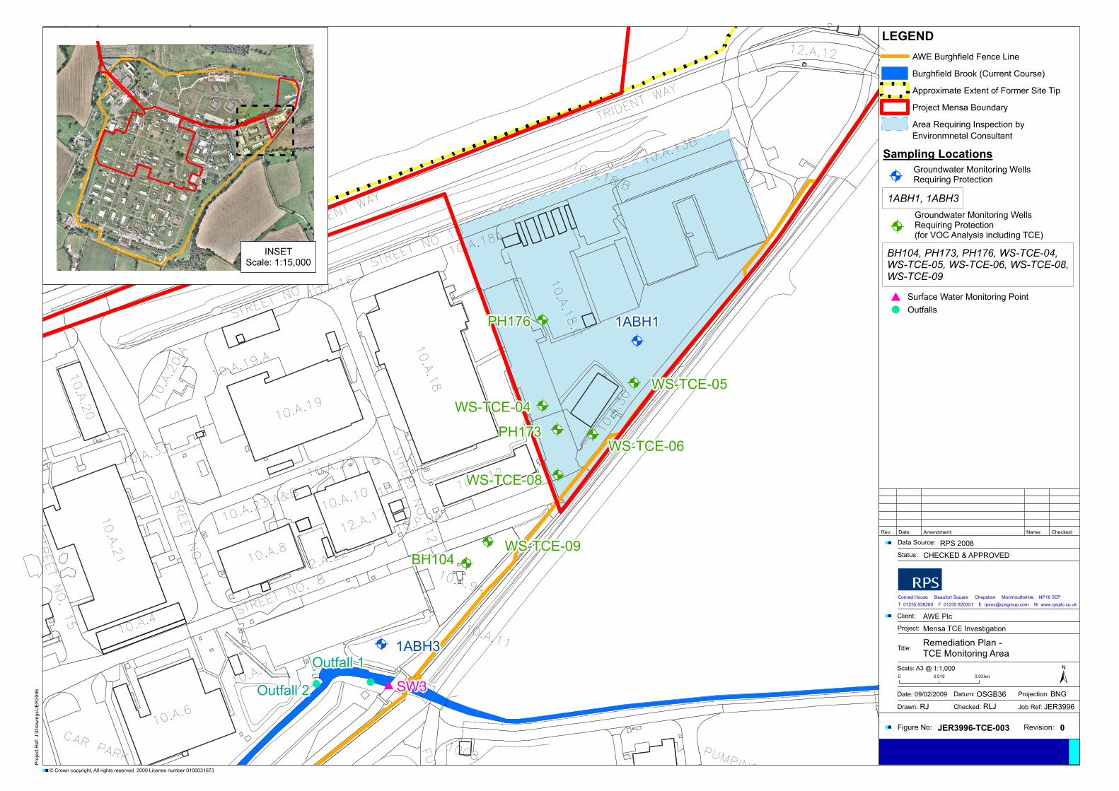
TRIDENT
WAY
CAR PARK
STREET
NO.8
STREETNO.12
TRIDENT
WAY
STREETNO.11
STREETNO.15
STREET
NO10
FUL
STREET
NO10
10.A.1
3B
10.A.8
10.A.30
10.A.1
8.C
10.A.18.B
10.A.1
8
10.A.12
10.A.19
10.A.19.
A
10.A.16
10.A.33
10.A.2
0
10.A.20.A
10.A.4
10.A.2
1
10.A.6
10.A.7
12.A.22
12.A.1
710.A.23.
A&B
11.D.9
10.A.10
10.A.23
10.F.9
10.A.18A
12.A.12
10.A.9A
10.F.9A
10.A.11
10G8 PUMPING
!! #
@A
@A
@A
@A
@A
@A
@A
@A
@A
@A 1ABH3
1ABH1
Outfall 2
Outfall 1
SW3
PH176
PH173
BH104WS-TCE-09
WS-TCE-08
WS-TCE-06
WS-TCE-05WS-TCE-04
Proj
ectR
ef:J
:\Dra
win
gs\J
ER
3996
Figure No: JER3996-TCE-003 Revision: 0
Date: 09/02/2009
Drawn:
Datum:
Checked:
Projection:
Job Ref:RJ RLJ JER3996
OSGB36 BNG
1:1,000Scale: A3 @0 0.030.015 km
Title:Remediation Plan -TCE Monitoring Area
Client: AWE PlcProject: Mensa TCE Investigation
Conrad House Beaufort Square Chepstow Monmouthshire NP16 5EPT 01235 838200 F 01235 820351 E [email protected] W www.rpsplc.co.uk
Status: CHECKED & APPROVED
Data Source: RPS 2008Rev: Date: Amendment: Name: Checked:
±
© Crown copyright, All rights reserved. 2009 License number 0100031673
LEGENDAWE Burghfield Fence Line
Burghfield Brook (Current Course)
Approximate Extent of Former Site Tip
Project Mensa Boundary
Area Requiring Inspection by
# Surface Water Monitoring Point! Outfalls
BH104, PH173, PH176, WS-TCE-04,WS-TCE-05, WS-TCE-06, WS-TCE-08,WS-TCE-09
INSETScale: 1:15,000
@AGroundwater Monitoring WellsRequiring Protection(for VOC Analysis including TCE)
1ABH1, 1ABH3
Sampling Locations
@AGroundwater Monitoring WellsRequiring Protection
Environmnetal Consultant

Remediation Method Statement
RPS Planning & Development AWE (B) TCE Monitoring Area May 2009 JER3996/TCE/RMS
Appendices

Remediation Method Statement
Appendix A
Summary of TCE Area Site Specific Target Levels (SSTLs)
RPS Planning & Development AWE (B) TCE Monitoring Area May 2009 JER3996/TCE/RMS

JER3996 Mensa Site Specific Target Levels
SUMMARY OF CLEA UK DERIVED GENERIC ASSESSMENT CRITERIA (GAC)and SGVs USED WITHIN THE HUMAN HEALTH RISK ASSESSMENT
Organics
Acenaphthene 88,000 CLEA UK Aromatics >C10 – C12 608 CLEA UK
Anthracene 440,000 CLEA UK Aromatics >C12 – C16 12,500 CLEA UK
Benzo(a)anthracene 281 CLEA UK Aromatics >C16 – C21 9,210 CLEA UK
Benzo(a)pyrene 28.1 CLEA UK Aromatics >C21 – C35 9,210 CLEA UK
Benzo(b)fluoranthene 281 CLEA UK 1,1,1 - Trichloroethane 551 CLEA UK
Benzo(ghi)perylene 44,000 CLEA UK Trichloroethene 6.46 CLEA UK
Benzo(k)fluoranthene 281 CLEA UK cis 1,2, Dichloroethene 1.87 CLEA UK
Chrysene 28,100 CLEA UK Benzene 1.67 CLEA UK
Dibenzo(ah)anthracene 28.1 CLEA UK Xylenes 344 CLEA UK
Fluoranthene 2,810 CLEA UK Bis (2-ethylhexyl)phthalate 1,120 CLEA UK
Fluorene 58,700 CLEA UK Dibenzofuran 625 CLEA UK
Indeno(123-cd)Pyrene 281 CLEA UK 1,1-Dichloroethane 1.04 CLEA UK
Naphthalene 290 CLEA UK 1,1-Dichloroethylene 1.24 CLEA UK
Phenanthrene 58,600 CLEA UK Maneb 1,560 CLEA UK
Pyrene 44,000 CLEA UK 2-Methyl Naphthalene 1,250 CLEA UK
C5-C6 41.6* CLEA UK Thiocyanate 61.5 CLEA UK
C6-C7 41.6* CLEA UK 1,1,2-Trichloroethane 0.634 CLEA UK
>C8 - C10 64.1* CLEA UK 1,2,3-Trichloropropane 2.24 CLEA UK
Aliphatics >C8 - C10 64 CLEA UK 1,2,4-Trimethylbenzene 1.53* CLEA UK
Aliphatics >C10 - C12 31,300 CLEA UK 1,3,5- Trimethylbenzene 1.09 CLEA UK
Aliphatics >C12 - C16 31,300 CLEA UK 4-Chlorotoluene 25,800 CLEA UK
Aliphatics >C16 - C21 614,000 CLEA UK Chlorobenzene 9.38 CLEA UK
Aliphatics >C21 – C35 614,000 CLEA UK 1,2-Dichlorobenzene 99.2 CLEA UK
Aromatics >C8 – C10 106 CLEA UK PCBs (non dioxin-like mixture) 3.13 CLEA UK
PCBs (dioxin-like mixture) 0.00063 CLEA UKCarbazole 14.7 PRGDi-n-butylphthalate 1810 PRGDibutyltin 53.7 PRG
Dieldrin 0.963 CLEA UK
Metals
Antimony 1,880 CLEA UK
Beryllium 1,960 CLEA UK
Cobalt 1,280 CLEA UK ExplosivesCyanide 50 Sniffer
Manganese 15,325 CLEA UK
Molybdenum 9,250 CLEA UK
Strontium 176,150 CLEA UK HMX 34,776 CLEA UK
Thallium 30 CLEA UK RDX 140 CLEA UK
Titanium 52,606 CLEA UK TNT 432 CLEA UK
Vanadium 468 CLEA UK Picric Acid No tox data NA
GAC (mg/kg)Determinant
GAC (mg/kg) Origin
Determinant GAC (mg/kg) Origin GAC (mg/kg) OriginDeterminant
Determinant
Origin

JER3996 Mensa Site Specific Target Levels
SUMMARY OF CLEA UK DERIVED GENERIC ASSESSMENT CRITERIA (GAC)and SGVs USED WITHIN THE HUMAN HEALTH RISK ASSESSMENT
Organics
Ethylbenzene 48,000 SGVPhenol 21,900 SGVToluene 150 SGV
Metals
Arsenic 500 SGVCadmium 1,400 SGVChromium 5,000 SGV
Lead 750 SGVMercury 480 SGVNickel 5,000 SGV
Selenium 8,000 SGV
Determinant SGV (mg/kg) Origin
Determinant SGV (mg/kg) Origin