Embed Size (px)
Citation preview

1Ball Aerospace Earth Science Technology Forum, June 2017
REMI - Reduced Envelope
Multi-Spectral Imager
for Sustained Land Imaging
Paula Wamsley, PI
A. Scotty Gilmore, PMEarth Science Technology Forum
June 2017
Ball Aerospace
REMI

2Ball Aerospace Earth Science Technology Forum, June 2017
LandSat: An Early & Enduring
Earth Observation Mission

3Ball Aerospace Earth Science Technology Forum, June 2017
Landsat Data are Widely Distributed for
Use in Science Research and Applications
https://landsat.usgs.gov/top-ten-uses
376 Abstracts for 2016
AGU Fall Meeting
5,270 entries in Google
Scholar for 2017

4Ball Aerospace Earth Science Technology Forum, June 2017
Sustainability
Continuity
Reliability
The goals of the SLI-T program are to research, develop, and demonstrate new measurement
technologies that improve upon the Nation’s current land imaging capabilities while at the
same time reducing the overall program cost for future SLI measurements.
The SLI-T program seeks to:
• Reduce the risk, cost, size, volume, mass, and development time for the next generation SLI
instruments, while still meeting or exceeding the current land imaging program capabilities;
• Improve the temporal, spatial, and spectral resolution of SLI measurements; and
• Enable new SLI measurements that can improve the program’s operational efficiency and
reduce the overall costs of the Nation’s land imaging capabilities.
Sustainable Land Imaging Program

5Ball Aerospace Earth Science Technology Forum, June 2017
Landsat 8/9 Top Level Architecture
Landsat Mission Operations Request for Information Industry Day, Floyd, V. & Nelson, J., USGS 2/2/2016.

6Ball Aerospace Earth Science Technology Forum, June 2017
Landsat 8 Space Segment - Sensors
Parameter OLI TIRS
Mass (kg) 470 236
Envelope Vol. (m3) 6.5 2.0
GSD (m) 30 (15 PAN) 100
Sensor Type Pushbroom Pushbroom
X-track Angular FOV
(°)
15 (185 km) 15 (185 km)
Wavelength (mm) 0.4–2.4 10–13
FPA SiPIN (VNIR),
HgCdTe (SWIR)
QWIP (Thermal), Actively
cryo-cooled
Primary Calibration On-board solar
diffuser
On-board blackbody
Ba
ll A
ero
sp
ace
NA
SA
LandSat 8
Segment Price% of
Mission
Space $555.1M 56.9%
Launch $157.1M 16.1%
Ground /
Ops$184.3M 18.9%
Mgmt $78.2M 8.1%
Total $974.7M 100%
Landsat 8 - $975 MSpace(56.9%)
Launch(16.1%)
Ground /Ops(18.9%)

7Ball Aerospace Earth Science Technology Forum, June 2017
REMI Design Concept Guided by
NASA/USGS Architecture Studies
What is an Architecture?
Payload
Spacecraft
Launch
Technology Infusion Plan
Mission Risk Class
Org Partnerships
Procurement Approach
16 Day Repeat, Average Availability (50% to100%)
8 D
ay R
ep
eat,
Avera
ge A
vail
ab
ilit
y (
0 t
o 1
00%
)Single Aperture Inst
Disaggregated VSWIR & TIR
LandSat 8-like Sats w/
New Sensors
TIRS FF
with
Sentinel-2
Combined Aperture,
Wide-Swath Inst
Future
Small
Sats
Future
Small
Sats

8Ball Aerospace Earth Science Technology Forum, June 2017
Scan Approach Opens the Design Space
Comparison of three different scan methodologies:
Whisk Broom, Push Broom, and Step-Stare.
▪ Whisk Broom: LandSat 1-7
▪ Push Broom: LandSat 8 & 9
▪ Step-Stare with Image Motion Correction: SLI-T/REMI
(SLI-T/REMI)

9Ball Aerospace Earth Science Technology Forum, June 2017
MODEL OUTPUTSMODEL INPUTS
Performance Model Developed
to Guide Design Trades
System
Reqs
Detector
Physics
Model
Spectral
Radiance
Optical
Throughput
Scan
Mechanism Step / Settle
Flight
ParametersAlt / Velocity
Stray Light
Performance
against Key Reqs
SNR
Edge Response
Extent
Edge Response
Slope
Aliasing Filter Sizes
Design Parameters
Optical Setup:
Focal Length
Optical Setup:
Aperture Diameter
Detector
Integration Time
FOR Pixel Binning

10Ball Aerospace Earth Science Technology Forum, June 2017
Derivation of REMI Reqs from SLIT RMA
SLIT Requirements from Reference Mission Architecture REMI Requirements (4,000 m AGL)
Band #
Band NameNominal
GSD (m)
Min Edge Slope (m-1)
Min Edge Slope
(mrad-1)
Max Half Edge
Extent (m)
Max Half Edge
Extent (mrad)
Nominal GSD1 (m)
Predicted GSD1 (m)
Equivalent GSD1 (m)
Min Edge Slope2
(m-1)
Min Edge Slope2
(µrad-1)
Max Half Edge
Extent2
(m)
Max Half Edge
Extent2
(µrad)
Max Aliasing4
1 Coastal Aero 30 0.027 0.0190 23.0 32.6 0.168 0.069 12.1 4.7588 0.0190 0.13 32.6 1.0
2 Blue 30 0.027 0.0190 23.0 32.6 0.168 0.069 12.1 4.7588 0.0190 0.13 32.6 1.0
3 Green 30 0.027 0.0190 23.0 32.6 0.168 0.069 12.1 4.7588 0.0190 0.13 32.6 1.0
4 Red 30 0.027 0.0190 23.5 33.3 0.168 0.069 12.1 4.7588 0.0190 0.13 33.3 1.0
5 NIR 30 0.027 0.0190 24.0 34.0 0.168 0.069 12.1 4.7588 0.0190 0.14 34.0 1.0
6 SWIR 1 30 0.027 0.0190 28.0 39.7 0.168 0.168 29.6 4.7588 0.0190 0.16 39.7 1.0
7 SWIR 2 30 0.027 0.0190 29.0 41.1 0.168 0.168 29.6 4.7588 0.0190 0.16 41.1 1.0
8 Pan 15 0.027 0.0190 14.0 19.9 0.168 0.069 12.1 4.7588 0.0190 0.08 19.9 1.0
9 Cirrus 30 0.027 0.0190 27.0 38.3 0.168 0.168 29.6 4.7588 0.0190 0.15 38.3 1.0
Margin
No MarginIncreasing Aperture
Incre
asin
g A
pe
rtu
re
Increasing Focal Length
Best Margin Against Multiple Reqs

11Ball Aerospace Earth Science Technology Forum, June 2017
All VSWIR Spectral Bands Demonstrated
TABLE A.2 SLI-T REFERENCE MISSION SPECTRAL IMAGE PERFORMANCE REQUIREMENTS
Band # Band Name Band #
Center Wavelength
(nm)
Center Wavelength
Tolerance (nm)
Minimum Lower Band Edge (nm)
Maximum Upper Band Edge (nm)
1 Coastal Aerosol 1 448 2 443 453
2 Blue 2 482 5 450 515
3 Green 3 562 5 525 600
4 Red 4 655 5 630 680
5 NIR 5 865 5 845 885
6 SWIR 1 6 1610 10 1560 1660
7 SWIR 2 7 2200 10 2100 2300
8 Panchromatic N/A 590 10 500 680
9 Cirrus 9 1375 5 1360 1390
10 Thermal 1 N/A 10800 200 10300 11300
11 Thermal 2 N/A 12000 200 11500 12000
3360 pixels
24
96
pix
els
VIS FPA
Blu
e B
an
d 2
Gre
en
Ba
nd
3
NIR
Ba
nd
5
Re
d B
an
d 4
Co
asta
l A
. B
an
d 1
1280 pixels1
02
4 p
ixe
ls
SWIR FPA
Ba
nd
9
Ba
nd
7
Ba
nd
6
▪ Proposal: 4 visible bands and 2 SWIR bands
– Demonstrate step-stare approach
– Multiple optical paths with single aperture
▪ Baseline: Enable all 5 visible bands, the
Cirrus band and both SWIR bands
Full VSWIR optical solution for SLI-T demo

12Ball Aerospace Earth Science Technology Forum, June 2017
Mechanical Packaging Concept Complete
▪ Initial packaging complete
▪ The VNIR and SWIR channels can be packaged within the allocated
volume.
▪ Inclusion of the TIR Channel will likely cause the system to exceed the
space allocation and may require a larger baseplate to hold all three
channels (still a manageable option)
VNIR Optical Path SWIR Optical Path TIR Optical Path

13Ball Aerospace Earth Science Technology Forum, June 2017
Scan Profile for (Airborne System)
0.45° cross-track
step size at 15 Hz
step rate;
5.2 s scan period;
4000 m AGL;
50 m/s ground
speed
Cross-track
In-track(back scan compensates for ground speed)
Ground
speed
Sensor integration time
at end of settle time
0.45° cross-track
step of 0.66°
filter width
provides 32%
cross-track scan
overlap. In-scan
overlap = 24%.

14Ball Aerospace Earth Science Technology Forum, June 2017
Scan Modeling (Airborne System)(OLI equivalent VIS IFOV = 42 urad)
Ground coverage plot (color indicates # of
VIS channels that sampled point on ground)
Ground
speed
VIS sensor field of view
(with individual
channels)
RMS motion of corner
pixels during integration
time
Ground sample
locations of
upper-left and
lower-right
corner pixels
during
integration time
LA-WASM
pointing angles
within field of
regard
FOR

15Ball Aerospace Earth Science Technology Forum, June 2017
Scan Modeling (On-Orbit Case)(OLI equivalent VIS IFOV = 42 urad)

16Ball Aerospace Earth Science Technology Forum, June 2017
Rate Table for Simulating Spacecraft Motion

17Ball Aerospace Earth Science Technology Forum, June 2017
Calibration Approach
▪ Absolute calibration performed during ground
testing with NIST traceable sources (blackbody &
lamps)
▪ Relative calibration in airborne configuration that
has been scaled against absolute calibration on
ground
▪ Heliostat testing (fall 2018) for direct comparison to
OLI2 (LandSat9)

18Ball Aerospace Earth Science Technology Forum, June 2017
Heliostat Testing Provides Direct
Comparison with OLI
▪ Solar source provides realistic
spectral profile for direct comparison
between REMI and OLI
▪ OLI planned Heliostat testing is Fall
2018
▪ REMI positioned outside the chamber
so that the beam is folded the
opposite direction for testing without
cleanliness and feedthrough
requirements
▪ University of Arizona is contracted for
OLI to perform atmospheric
transmission measurements during
Heliostat testing from roof
Solar beam on
chamber
19Ball Aerospace Earth Science Technology Forum, June 2017
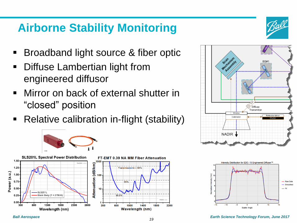
Airborne Stability Monitoring
▪ Broadband light source & fiber optic
▪ Diffuse Lambertian light from
engineered diffusor
▪ Mirror on back of external shutter in
“closed” position
▪ Relative calibration in-flight (stability)

20Ball Aerospace Earth Science Technology Forum, June 2017
Mechanical Layout in Twin Otter
Twin Otter
Twin Otter Open View

21Ball Aerospace Earth Science Technology Forum, June 2017
2018Q1/2
Eng. Flight
VSWIR Bands
Flight Plans
2017Q4
Lab Testing
Rate Table
2018Q3/4
Data Flight
VSWIR Bands
2019Q2/3
Science
Flights
▪ Eng. Flights ensure proper interfacing and functionality while airborne
▪ Data Flights used to generate data used to validate concepts
▪ Science Flights used to acquire data of specific interest to the science community

22Ball Aerospace Earth Science Technology Forum, June 2017
Acknowledgements
▪ Funding from ESTO/SLI-T, Contract No. NNX16AP63G
▪ Ball Team:
– Tom Kampe, Optics
– Bob Warden, Mechanical
– Kyle Solander, Electronics
– Jonathan Fox, Software
– Homero Gutierrez, Scan Mechanism
– Lyle Ruppert, L1B Data Processing
– Bill Good, Aircraft Ops

23Ball Aerospace Earth Science Technology Forum, June 2017
THANK YOU!