Embed Size (px)
Citation preview

Remote Controlfor
TDR range
Remote Control Manual
REV3-13-9

Contents
Safety and maintainance information 3
Keyboard 5
Remote control configuration 5
Keys functions 7
Changing RF channel 8
Change of transmission channel on the handheld remote 9
Change of transmission channel on the power board 10
Board output connection 11
Power supply 12
Valves box 12
Troubleshooting 13
Parts List 14
Manual override 16

www.major-equipment.com 3
REMOTE CONTROLSAFETY AND MAINTAINANCE INFORMATION
• Never open the protection box of the remote control.• Should the remote control be damaged, or should liquids have soaked in, have the item checked by a
service point.• Never pull the cables in order to disconnect the remote control charger, but remove the connectors in the
right way.• If the device is provided with an electro-valve control box, remind that this is equipped with a fuse for
protection against power supply inversions and current overflowing. In case the fuse breaks down, replace it with an equivalent one.
• Do not lay the device cables (e.g. load cell cables, data transmission cables, cables to control relay boards, etc.) near supply cables of other electric or electronic devices.
• Supply the device with tensions consistent with the technical features of the product.• Have installation and maintenance work carried out by qualified staff.• Working on the electro-valve control box, by making connections or adjustments which are not authorized
by the manufacturer will void the warranty.• Do not lay the cables which are connected to the remote control charger near moving mechanical parts.• Once you have finished working with the device, we suggest you store it on its holder.• Before cleaning the machine with high-pressure water, protect the remote control against possible water
infiltrations. We also remind you to be extremely careful and not expose electronics, cables and other optionals to direct water jets.
• It is possible to clean the remote control outside by using a soft and damp cloth, avoiding solvent or abrasive substances, sharp or cutting objects which can damage the device.
• Do not expose the remote control to temperatures higher than the limits indicated in the technical features.• In order to reach a longer duration, do not expose the remote control directly to atmospheric events, such
as rain, snow, frost, etc.• Do not use sharp or cutting tools to press the keys.• Before carrying out installation, maintenance and reparation works on the system, disconnect the power
supply.• Before carrying out welding on the machine, disconnect all the cables from the remote control.• In case of welding on the machine, place the grounding clip near the welding point, in order to prevent
electric current from passing through the load cells.• In case of welding on the device/machine, disconnect the electro-valve control box and the electronic
equipment, by unplugging the power supply cable, all the electro-valve cables and the connection cable to the handheld remote control.
• We suggest NOT to use electro-valves which have the connection to the body of the electro-valve itself.• All responsibility for installation, maintenance and reparation works falls on the person who carried them
out.• The constructor of the machine on which the device is installed takes on the responsibility to fix the parts
of the device properly, in order to prevent any dangerous contact of the operator with the dangerous area. In particular, if the device can control electro-valves, when the operator pushes a button, he is supposed to be aware of the corresponding movement on the machine.
• It is responsibility of the constructor of the machine on which the device is installed to:• Evaluate risks and safety of the system• Provide the correct power supply on the device TELE-RF, in order to guarantee the correct functioning
of the device in full respect of the regulation EN 60204-1.
Do not use high-pressure devices to clean the remote control and charger

www.major-equipment.com4
TECHNICAL INFORMATION (TELE-RF-V14C02 model)Analogical keyboardABS CaseProtection IP65Size L 105 x H 240 x P 56Weight 740 grDisplay LCD alphanumeric backlit (2 lines, 16 characters per line)Memory Eeprom non volatileBattery 4 batteries, type AA NiMH rechargeableBattery life 8hBattery charge time 5hOperating conditions -20 °C + 60 °CRelative Humidity 95 %Supply voltage From 11 to 28 VdcAbsorbed power 5 VA during the charge of the battery – maximum 15 VATransreceiver A868 MHz in FMAntenna RF InsideDisplay visible also in full sunlightProtection against radiofrequency interferenceSuppression of the interference superposed to the power supplyFaulty battery signal and controlLow-tension signalOperating ranging: over 50 m.4 available transmission channels, for the connection of 4 devices contemporarily
Connect remote control charger to 12V DC ONLY
Batteries
Charge connectors
Batteries
Base 12V charging unit
Plug
Remote Control

www.major-equipment.com 5
KEYBOARD
SWITCH ON THE REMOTE
SWITCH OFF THE REMOTE
· CONTRAST· BATTERY· SOFTWARE RELEASE· CLOCK EMERGENCY STOPBLOCKS ALL THE ACTIVE OUTPUTSTO DISABLE: PRESS THE KEY MENU KEY UPSelect options and submenus, scroll lists KEY DOWNSelect options and submenus, scroll lists
KEY FUNCTION
FUNCTION OPERATION DISPLAY
Configuration Menu To access the main menu, press the key for few seconds.
Scroll the list of available submenus
Press and to select the submenu1. CONTRAST2. BATTERY3. SOFTWARERELEASE4. CLOCK
Enter the submenus to make changes
Once you have chosen which submenu you want to
change, press the key to enter the modification
mode. By pressing the and keys and you can select the new value.
Save the changes or leave without saving
Press to save changes
Press to quit without saving.Leave the configuration menu Press to leave the configuration menu.
REMOTE CONTROL CONFIGURATION

www.major-equipment.com6
FUNCTION OPERATION DISPLAY
CONTRAST
In this menu the value of the contrast of the LCD display is shown.
Once you are in the menu, use and to select the contrast value you desire between -10 and +10.
Once the contrast is set, press to confirm and save,
or to exit.
BATTERY
Power supply modes are displayed in this menu. If the device is fitted with RF communication, the information about battery is also shown.
Use and to navigate through the menu. T=0 : Power supply with 1800 mA/h battery pack T=1 : Power supply with 1600 mA/h battery pack T=2 : Power supply with NiMH batteries T=F : Power supply connected to the power board by cable.By selecting a power supply mode which does not correspond to the actual one, the will show invalid figures.
Press the key to exit.NOTE: By selecting T=F the battery charge value will not be displayed; if the device is instead supplied through batteries, the charge value will be displayed every 10 seconds.
SOFTWARE RELEASEThe software release version is displayed in this menu.
Once you have seen the version, press to exit.
CLOCK
Date and time is shown in this menu.
To modify date and time, press to enter into the
modify mode and use the keys and to modify
the selected value. Press to go on to the following
parameter, or to exit without saving.
Scroll through the parameters by pressing to save the changes.

www.major-equipment.com 7
KEYS FUNCTIONSFUNCTION OPERATION DISPLAY
Left wing UpLeft wing Down / Float
By keeping this key pressed, the left wing rises up.By releasing the key, the left wing stops.
By keeping this key pressed, the left wing goes down and floats the same time.By pressing the key again, descent and floating stop.A red LED light indicates that the action is active (see diagram below).
Rear deck UPRear deck DOWN/ Float
By keeping this key pressed, the rear deck goes up.By releasing the key, the rear deck stops.
By keeping this key pressed, the rear deck goes down and floats the same time.By pressing this key again, descent and float stop.A red LED light indicates that the action is active.
Right Wing UPRight Wing DOWN/
Float
By keeping this key pressed, the right wing rises up. By releasing the key, the right wing stops.
By keeping this key pressed, the right wing goes down and floats the same time.By pressing the key again, descent and floating stop.A red LED light indicates that the action is active.
Rear deck top linkblock
Rear deck top linktransport
By keeping this key pressed the rear deck top linkblocks. By releasing this key, the rear deck top link unblocks.
By keeping this key pressed the rear deck goes up/down. By releasing the key, the rear deck stops moving.
TRANSPORT
Red LED light indicated that the valve is open.

www.major-equipment.com8
Changing RF channel
The first 9 keys (T1-T9) have the following functions in programming or installing phase:
KEY FUNCTIONARROW UP
Selection of submenus and options.Scrolling lists.
Changing the selected value.ARROW DOWN
Selection of submenus and options.Scrolling lists.
Changing the selected value.RIGHT ARROW
Selection of submenus and options.Scrolling lists.
Positioning the blinking cursor.LEFT ARROW
Selection of submenus and options.Scrolling lists.
Positioning the blinking cursor.ENTER
Entering the changing mode.Confirming the selection.Saving the choices made.
ESCLeaving the context without saving any change.
www.major-equipment.com 9
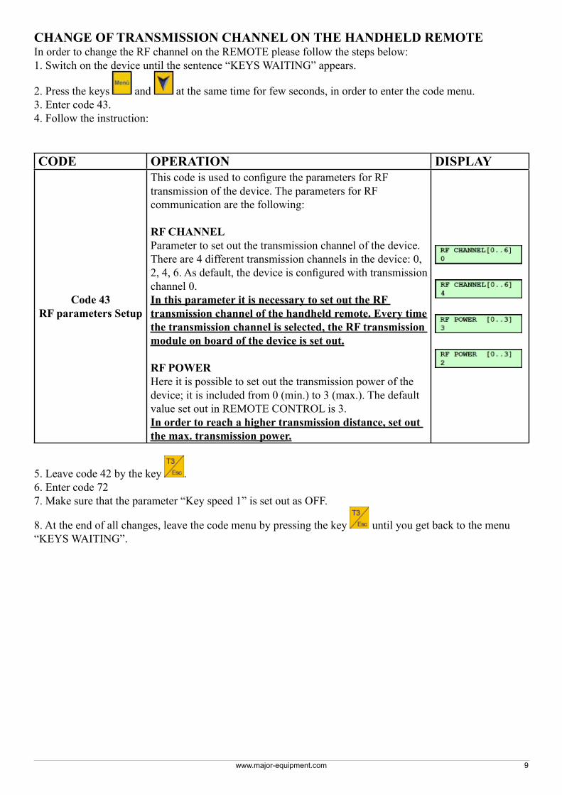
CHANGE OF TRANSMISSION CHANNEL ON THE HANDHELD REMOTEIn order to change the RF channel on the REMOTE please follow the steps below:1. Switch on the device until the sentence “KEYS WAITING” appears.
2. Press the keys and at the same time for few seconds, in order to enter the code menu.3. Enter code 43.4. Follow the instruction:
CODE OPERATION DISPLAY
Code 43RF parameters Setup
This code is used to configure the parameters for RF transmission of the device. The parameters for RF communication are the following:
RF CHANNELParameter to set out the transmission channel of the device.There are 4 different transmission channels in the device: 0, 2, 4, 6. As default, the device is configured with transmission channel 0.In this parameter it is necessary to set out the RF transmission channel of the handheld remote. Every time the transmission channel is selected, the RF transmission module on board of the device is set out.
RF POWERHere it is possible to set out the transmission power of the device; it is included from 0 (min.) to 3 (max.). The default value set out in REMOTE CONTROL is 3.In order to reach a higher transmission distance, set out the max. transmission power.
5. Leave code 42 by the key .6. Enter code 727. Make sure that the parameter “Key speed 1” is set out as OFF.
8. At the end of all changes, leave the code menu by pressing the key until you get back to the menu “KEYS WAITING”.

www.major-equipment.com10
CHANGE OF TRANSMISSION CHANNEL ON THE POWER BOARDIn order to change the RF channel on the Power board please follow the steps below:1. Disconnect the power to the POWER box.2. Unscrew 4 plastic screws as shown below.
3. Open the cover
4. Find the dip-switch on the board (see picture below):
Position ONPosition OFF
5. Move the contacts, in order to get the desired configuration.
CONTACT 2 CONTACT 1 RF CHANNEL CONTACT 3 RF POWER0 0 0 0 30 1 2 1 11 0 41 1 6
6. Place the cover in its original position and fasten 4 plastic screws. Reconnect the power.

www.major-equipment.com 11
Boardoutput
Output Function Cabletype
Lenght mm (total)
Lenght mm (ext.)
HoleN°
O1 V1 Rear platform top connection block 2x1 700 250 1O2 V3 Rear platform Up 2x1 700 250 2O3 V5 Left Wing Up 2x1 700 250 3O4 V7 Right Wing Up 2x1 700 250 4O5 V9 General Valve 2x1 700 250 5O6 V2 Rear platform top connection transport 2x1 810 360 6O7 V4 Rear platform down / float 2x1 870 420 7O8 V6 Left wing down / float 2x1 800 350 8O9 V8 Right wing down / float 2x1 950 500 9O10 V6a Left wing down / float (2nd valve) 2x1 1020 570 10O11 V8a Right wing down / float (2nd valve) 2x1 1020 570 11
The cable length must be defined according to the Electro-valve head. Cut as indicated in the column “Length mm (total)”. Inside the box there must be 450 mm cable, of which 300 mm peeled off for internal wiring and 150 mm for the adjustment of the cable length.
CABLE TOTAL LENGTH: 8,97 m ≈ 9 m
NOTES FOR MOUNTING:The protection fuse must not be mounted into the box, it must be on the cable.The electro-valve heads are provided with a red led.The electro-valve heads must be filled with silicon.The electro-valve heads of the outputs V6a and V8a are the other way round in comparison to the other fittings.
Mounting direction heads V1 … V8 Mounting direction heads V6a and V8a
On the valve box there must be a label indicating “FUSE 25A MAX”Place a label on the charger of the handheld control indicating “12-24 Vdc”The emergency key has not to be mounted onto the valve box.VARF board is treated with transparent and insulating spray paint.
Board output connection

www.major-equipment.com12
The power supply cable, as shown into the picture above, is divided into 2 connected parts.
The first piece of cable is connected directly to the instrument and its total length is 2300 mm (of which 300 mm peeled for internal wiring), including connector. A 2x6 mm cable should be used. The wires into the cable must be connected to the 2- poles connector and covered with heat-shrinking material with glue.
In this first piece of cable there is a fuse-holder, which is positioned 250mm after the PG cable gland of the power supply cable. Also in this case the connections must be covered with heat-shrinking with glue.
The second piece of cable has a 3000 mm total length, connectors included. In order to obtain the most precise cable size, cut the cable 3000mm long. In this case the cable used is 2x6 mm.
Connector’s length:• 2 poles female connector length : 35 mm• 2 poles male connector length: 40 mm• COBO connector length: 70 mm• Fuse holder length: 40 mm
Power supply
Valves box
ATTENTION: From the box to the bending angle of the electro-valve cable there is a distance of 35-40mm.

www.major-equipment.com 13
TROUBLESHOOTINGError description Action to be carried out Effect Solution
The REMOTE doesn’t switch on, or the message Low Bat appears.
(If the REMOTE is connected to the Charge Station).
Check that the emergency keys on the device and on the power board are both released.
One or both keyswere not released.
At least onr key was not released. By releasing it, the system has been switchedon and it is ready to work.
Both keys werereleased.
There is a fault, carry out the operationdescribed at the following point.
Check that the power supply is conformed to the technical features of the product.
Power supply is notconformed to theproduct features.
The wrong type of power supply can cause this problem. Provide the device with the power supply indicated into the productspecifications.
Power supply isconformed to theproduct features.
There is a fault. Carry out the operationindicated into the following point.
Check that the power supply cable is not interrupted or damaged, and that the power supply plug and the battery clamps are not oxidized; eventually replace them.
The unit switcheson.
There was a fault on the power supplycable of the relay board. Now it is possible to start working again.
The unit does notswitch on.
The fault can be on the junction cable.Carry out the operation indicated at thefollowing point.
Check that the junction cable is not interrupted or damaged, and that the connector’s pins are not oxidized or broken.
The junction cableor the connectorsare damaged.
The junction cable is damaged and doesnot provide electric power supply to theREMOTE. Replace it.
The connection cable and connectors are safe.
The problem can be due to an electronicboard fault. Call the service.
Your REMOTE doesn’t switch on anymore.Your REMOTE doesnot recharge anymore.
Charge the device for at least 12 hours.
After the 12 hourscharge the deviceswitches on.
The battery was exhausted, now the deviceworks correctly. If the operating time of thedevice begins to decrease, replace the battery pack.
The device does not switch on evenafter the 12-hourcharge.
The battery pack of the device is faulty ordamaged. Replace it.
On the display of the REMOTE the message “NO CONNECTION” isdisplayed.
Get closer to the power board with the palmtop in your hands.
The REMOTE starts working again.
The REMOTE was too far from the power board. Reduce the distance between the REMOTE and the power board to allow the device to work correctly.
The REMOTEdoesn’t work.
The problem could be in the powerboard or in the remote control. Carry out theoperation indicated below to verify the nature of the fault.
Check that the emergency buttonhas been released, and that the red led on the box turns on.
The led is on andthe emergency keyis released.
The power board or the remote control aredamaged. Call the service.
The led is off andthe emergency keyon the board is notreleased.
The power board was off. Release theemergency key to switch it on again andverify that the system starts functioningagain. If the message “NO CONNECTION”continues to appear, carry out the operationdescribed in next point.
Verify the REMOTE and the power board integrity, being particularly aware of cracks.
The devices are notwhole and there aresome cracks.
Some humidity may have entered thedevice. Call the assistance for an eventualdevice replacing.
The devices do not show any sign of damage.
A malfunctioning on one of the electronicboards has occurred. Call the service.

www.major-equipment.com14
TROUBLESHOOTING (continued)Error description Action to be carried out Effect Solution
By pressing a key, the associated output is not activated.
Please see “Board output connection” section of this manual, disconnect the cable from the non-functioning electro-valve, switch on the device, activate the non functioning output and verify with the multimeter that while the output is active the 12V are present on the cable.
There are 12V on the cable when the REMOTE output is activated.
The electro-valve is damaged. Call the service.
There are not 12V on the cable when the REMOTE output is activated.
The cable could be seriously damaged or there could be an electricity problem. Carry out the action indicated at the following point.
Check that the junction cable with the electro-valve is not damaged.
The junction cable is seriously damaged.
The junction cable is seroiusly damaged, so the 12V don’t do not reach the electrovalve. Call the service.
The junction cable is not damaged.
There is a problem on the power board, contact service.
The system turns off or resets when another output is activated.
Please see “Board output connection” section of this manual, disconnect the cable of the malfunctioning output, then try again.
The REMOTE returns working correctly.
There is a short circuit on an electro-valve, it has to be replaced.
The REMOTE continues to reset or to turn off
There is a short circuit on the junction cable to the electro-valve, or directly on the board. Call the service.
Parts List
Item Part No Description1 PTM-V14-C02a RECIEVER BOX & CIRCUIT BOARD2 S18211TC411 DIN PLUG WITH LED3 S18211TC411-R DIN PLUG WITH LED -Reverse mounted4 RC-PTM-V14-C02-C1 2 X0.5 Cable 250mm long (outside)5 RC-PTM-V14-C02-C2 2 X0.5 Cable 380mm long (outside)6 RC-PTM-V14-C02-C4 2 X0.5 Cable 570mm long (outside)7 RC-PTM-V14-C02-C5 2 X0.5 Cable 380mm long (outside)8 RC-PTM-V14-C02-C6 2 X0.5 Cable 570mm long (outside)9 RC-PTM-V14-C02-C7 2 X0.5 Cable 380mm long (outside)10 RC-PTM-V14-C02-label FUZE LABEL11 RC-PTM-V14-C02-mount MOUNTING PLATE12 RC-PTM-V14-C02-C3 2 X0.5 Cable 380mm long (outside)13 RC-PTM-V14-CAB01 BREAKAWAY CABLE14 RC-PTM-V14-CAB02 2ND CABLE WITH 25A INLINE FUSE15 RC-PTM-V14-REM REMOTE CONTROL16 RC-PTM-V14-RCH REMOTE CHARGER BASE PLATE

www.major-equipment.com 15

www.major-equipment.com16
Manual overrideIn the event of Manual Override, in order to lower wings, please follow this procedure:1. Turn off remote control (Disconnection is not necessary);2. Press the black tap in and turn it clockwise (Figure A);3. Turn the screw anti-clockwise until fully open (Figure B);4. Press the button fully (Figure C).
Figure BTop screw (shown) - right wing.
Bottom screw - left wing.
Figure CButton shown will make the wing go
down.Button on the opposite side will raise the
wing.
This shows the normal position, threaded in.
This shows the manual override position with the thread out. IMPORTANT - The check will not work in this position & this should be used for maintenance purposes only. Manual over-ride should not be used when operating the machine normally.
Figure A
PRESS
TURN
ATTENTIONKeep clear when raising and lowering
wings.
Press the knob in and turn
The knob will lock in this position
REMOTE CONTROL