Embed Size (px)
Citation preview
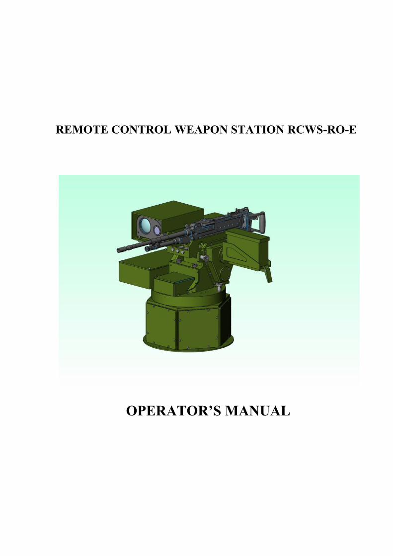
REMOTE CONTROL WEAPON STATION RCWS-RO-E
OPERATOR’S MANUAL
1
PREFACE
The Operator’s Manual (OM) has been prepared to instruct the user in the operation, care and
maintenance of the system RCWS-RO-E
Issued copies of the OM will not be updated automatically and holders must ensure that they
are in possession of the latest issue.
Every endeavour has been made to confirm that the information contained in the OM is
correct, but the user should additionally ensure that all normal safety procedures are followed.

2
Page left blank
3
T A B L E O F C O N T E N T S
Page.
1. Introduction ................................................................. 5
2. General Description ..................................................... 6
3. System Description ......................................................7
4. Delivery Kit ............................................................... 21
5. Technical features ..................................................... 21
6. Safety rules ................................................................ 23
7. Mounting and Operating Instructions ........................24
7.1 Preliminary checking..............................................247.2 Starting the system.................................................257.3 Operating the system..............................................26
8. Maintenance .............................................................. 39
9. Troubleshooting ........................................................ 43
10. Spare parts ................................................................. 46
11. Storage and Transportation Conditions ..................... 48
12. Warranty .................................................................... 48
Annexes:
Annex 1 Block diagramAnnex 2- Exploded drawingsAnnex 3 GPMG7.62 User Handbook
4
Abbreviations
OM – Operator’s Manual
RCWS-RO-E - Remote Control Weapon Station (Romanian, for Egypte)
CP - Control Panel
BS - Sensors Block
CBS – Control Board for Sensors block
DIS - Display
WA- Weapon Assembly
PCB - Printed Circuit Board
LED - Light Emitted Diode
CDM - Control Distribution box- Machine
CDT - Control Distribution box – Turret
TC - Thermal Camera
NUC - Non Uniformity Correction
FOV - Field Of View
DC - Day Camera
MH - Horizontal Motor
MV- Vertical Motor
IH- Horizontal Incoder
EV- Vertical Encoder
STAB-H - Horizontal STABilization module
STAB-V - Vertical STABilization module
BF - Brake block
SBF - Control Brake Block
SR - Slip-Rings
GPMG 7.62 – Ceneral Purpose Machine Gun 7.62 calibre
LB – long burst
SB – short burst
SS – single shot
SOC- State Of Charge
BIT- Built In Test
5
1. Introduction
Remote Controlled Weapon Station (RCWS-RO) is a light-
weight weapon system fitted with a light machine gun for use on a variety of soft
skinned, light armoured and Mine Protected Vehicles (MPV). Some typical applications
are: protection against the dismounted threat, providing a first order defence for logistic
transport carriers, as well as support and repair vehicles. The system can be operated by
one crew member from under or behind cover
The RCWS-RO-E fitted with an 7.62 GPMG Machine Gun is effective against
enemy targets up to a range of 600m. For easy operation in a typical vehicle cabin, the
RCWS-RO-E operator controls the turret and fires the weapon using Gunner Station
with a simple Human Machine Interface (HMI), consisting of a display (DIS) and a
Control Panel (CP) containing a Joystick..
Video images received from the video cameras on the turret are displayed to the
operator. The display indicates fixed ballistic aiming lines to help the operator compensate
for target range.
The weapon is remotely operated including the aiming and safe firing of the
weapon which is done electrically. The turret can be factory configured to limit the arc of
fire in both elevation and traverse.
RCWS-RO-E can be supplied in different configurations catering for different
weapon types and optical sensors. This document, however, addresses exclusively the
Manroy 7.62mm Machine Gun. The standard configuration of RCWS-RO-E
incorporates a day video CCD camera and a Thermal Camera (TC)
System benefits:
- Allows under-armour protected target engagement without exposing the crew
- Provides better accuracy than a typical weapon ring station
- Provides "on-the-move" engagement capability
- Accurate target confirmation I identification is possible using the video image.
- Provides continuous fire command and control, day and night, in harsh
environmental conditions (dust, smoke, fog), with a high probability to discover and
destroy the enemy targets.
- Allows both, field observation and gun firing towards the targets
- RCWS-RO is electrically controlled in the basic mode. It may be manually
controlled too, as an auxiliary mode
6
2. General description
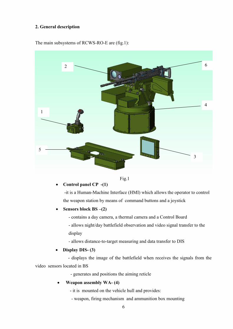
The main subsystems of RCWS-RO-E are (fig.1):
Fig.1 Control panel CP -(1)
-it is a Human-Machine Interface (HMI) which allows the operator to control
the weapon station by means of command buttons and a joystick
Sensors block BS –(2)
- contains a day camera, a thermal camera and a Control Board
- allows night/day battlefield observation and video signal transfer to the
display
- allows distance-to-target measuring and data transfer to DIS
Display DIS- (3)
- displays the image of the battlefield when receives the signals from the
video sensors located in BS
- generates and positions the aiming reticle
Weapon assembly WA- (4)
- it is mounted on the vehicle hull and provides:
- weapon, firing mechanism and ammunition box mounting
1
2
3
4
5
6
7
- sensor block mounting
- control boxes and actuating mechanisms mounting
- slip-rings and bearing mounting
- Actuating mechanisms -provides azimuth (transverse) and elevation
motions. Contains motors with brakes and gear boxes
- control boxes for tranverse and elevation motions
- gyrosensors for stabilisation –transverse and elevation motion
- encoders for motion feedback- incoder for transverse, encoder for
elevation
NOTE: All the subsystems mentioned above are mounted in Weapon Assembly WA (4); only
the control distribution box CDM ( for transverse motion) and the control boxes for brakes
(BF abd SBF)are mounted in the cabin under the roof (5)
Weapon - (6)
- it is a 7.62 GPMG coaxial machine gun -electrically controlled.
- it is mounted on WA
Cables (not shown)
- provide power supply and subsystems interconnections
3. System description
3.1 Control panel CP
Location: in the cabin, in front of the rear left seat
It is a microcontroller-based subsystem which allows the operator to control
the weapon station by means of a joystick. CP contains a microcontroller PCB, a
rugged case with control buttons & LEDs and a joystick.
CP functions:
commands:- azimuth and elevation movements for the weapon assembly WA
- FOVs switching for the thermal camera or day camera
- thermal camera polarity (white hot/black hot), NUC, focus
- operation modes: observing, target acquisition and firing
- auxiliary modes : boresighting, reference setting, elevation limits setting,
CDM and CDT drivers setting, errors displaying
- returning to pre-established “Reference” (ZERO) position
8
- fire control (single shot, short burst, long burst -continuous)
- stabilization mode
- power supply for the whole system
acquires :
- “Zero” position of the weapon assembly WA
- “UP” and “DOWN” limit positions for the weapon
- WA functionality information
- BS functionality information
signalizes
- components status: green - OK, red or blinking red - ERROR , blinking
green-red - power supply under 18 V
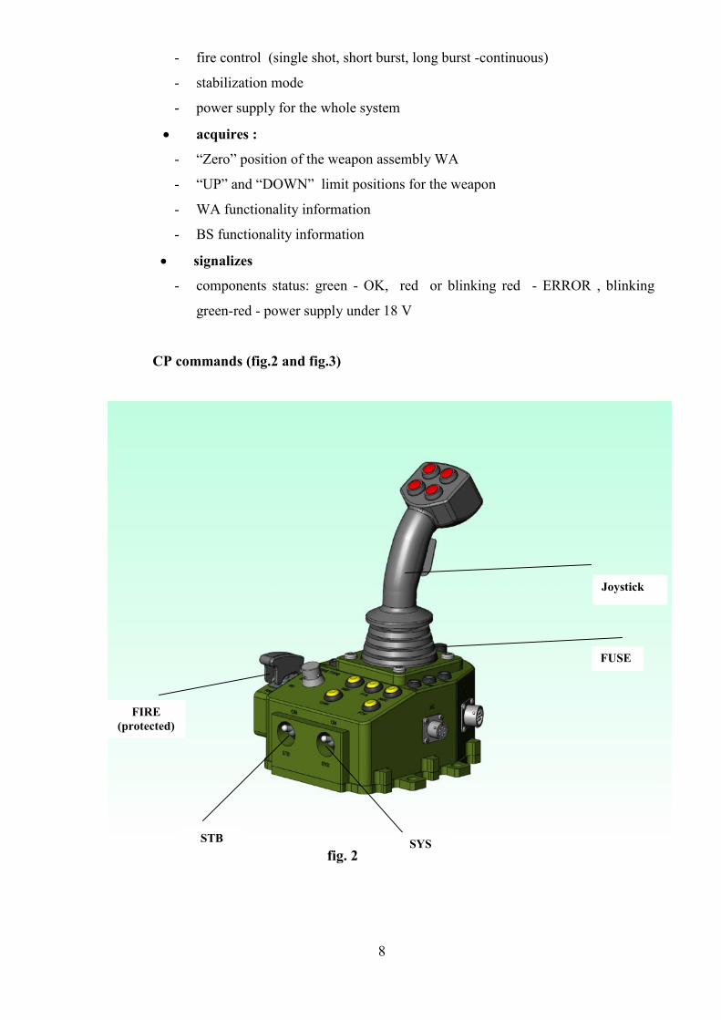
CP commands (fig.2 and fig.3)
fig. 2
Joystick
SYSSTB
FIRE(protected)
FUSE
9
Switches (fig 2)
SYS-System
STAB- Stabilization
FIRE- firing start (protected switch)
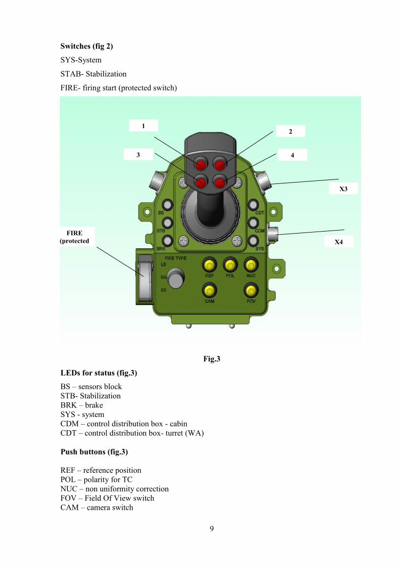
Fig.3
LEDs for status (fig.3)
BS – sensors blockSTB- StabilizationBRK – brakeSYS - systemCDM – control distribution box - cabinCDT – control distribution box- turret (WA)
Push buttons (fig.3)
REF – reference positionPOL – polarity for TCNUC – non uniformity correctionFOV – Field Of View switchCAM – camera switch
21
3 4
FIRE(protected
)
X3
X4
10
Rotary switch (fig.3)
FIRE TYPELB – long burstSB – short burstSS – single shot
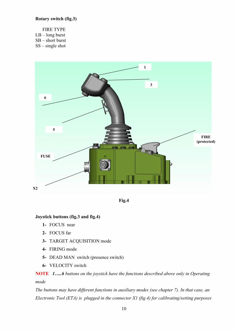
Fig.4
Joystick buttons (fig.3 and fig.4)
1- FOCUS near
2- FOCUS far
3- TARGET ACQUISITION mode
4- FIRING mode
5- DEAD MAN switch (presence switch)
6- VELOCITY switch
NOTE 1…..6 buttons on the joystick have the functions described above only in Operating
mode
The buttons may have different functions in auxiliary modes (see chapter 7). In that case, an
Electronic Tool (ETA) is plugged in the connector X1 (fig.4) for calibrating/setting purposes
5
6
FUSE
FIRE(protected)
X2
1
3
11
Connectors: (fig.3 and fig.4)
XI- service connector
X2- communication connector
X3- Power supply connector
X4- Display connector
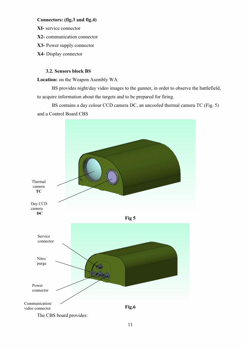
3.2. Sensors block BS
Location: on the Weapon Asembly WA
BS provides night/day video images to the gunner, in order to observe the battlefield,
to acquire information about the targets and to be prepared for firing.
BS contains a day colour CCD camera DC, an uncooled thermal camera TC (Fig. 5)
and a Control Board CBS
Fig 5
Fig.6
The CBS board provides:
Thermalcamera
TC
Day CCDcamera
DC
Serviceconnector
Nitropurge
Powerconnector
Communication/video connector
12
- power supply distribution to the components
- video signals control
- command signals distribution for video sensors
- protection for the sensors
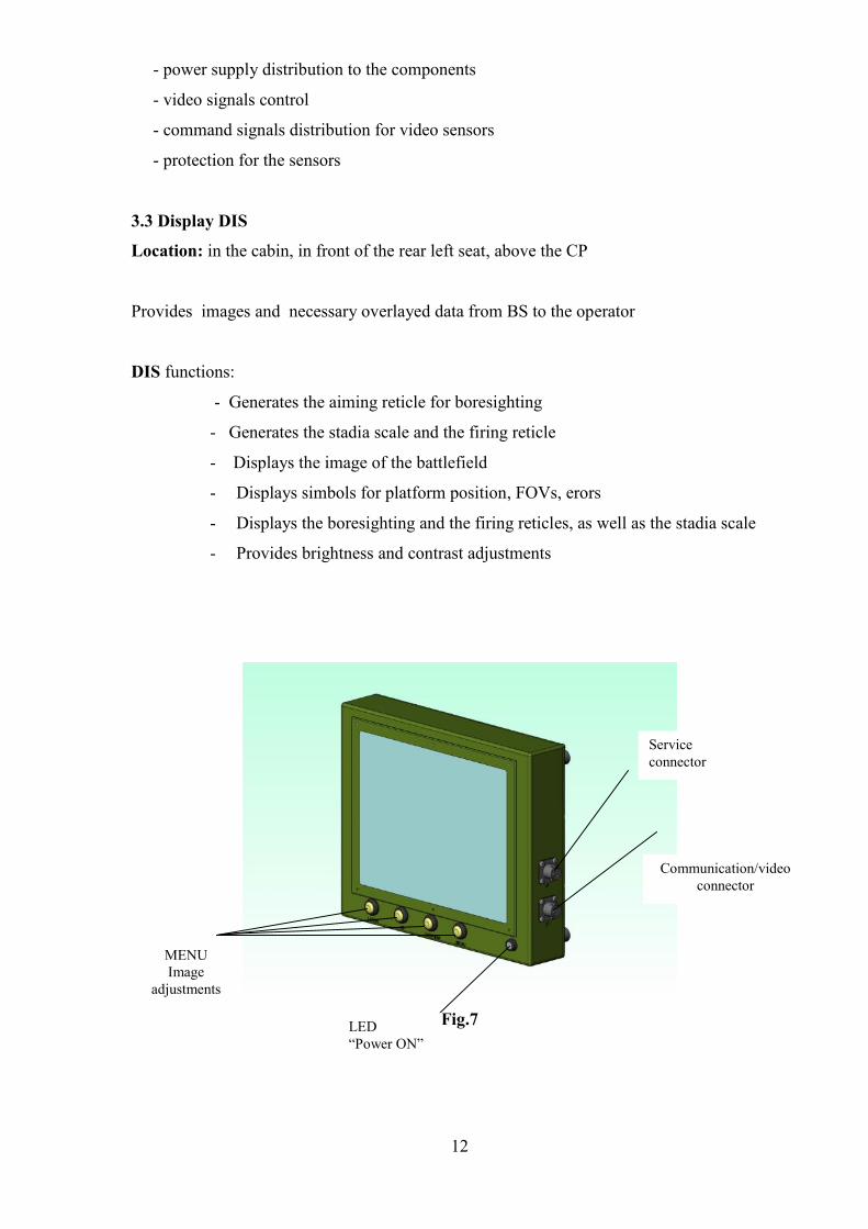
3.3 Display DIS
Location: in the cabin, in front of the rear left seat, above the CP
Provides images and necessary overlayed data from BS to the operator
DIS functions:
- Generates the aiming reticle for boresighting
- Generates the stadia scale and the firing reticle
- Displays the image of the battlefield
- Displays simbols for platform position, FOVs, erors
- Displays the boresighting and the firing reticles, as well as the stadia scale
- Provides brightness and contrast adjustments
Fig.7
Serviceconnector
Communication/videoconnector
LED“Power ON”
MENUImage
adjustments
13
3.4 Weapon Assembly WA
It is mounted outside the vehicle, on the roof.
Contains:
- weapon cradle which will receive the 7.62 GPMG to be mounted on
- motors and resolvers for azimuth/elevation motion of the weapon
- gyro sensor blocks for stabilization system
- encoders for stabilization systems
- control boxes for azimuth/elevation CDM/CDT
- sensors block BS
- brake block BF and control brake block SBF
- ammunition box
- ballistic protection.
NOTE: Control Distribution box – Machine CDM, brakes block BF and control brakes
block SBF are mounted inside the cabin, under the roof
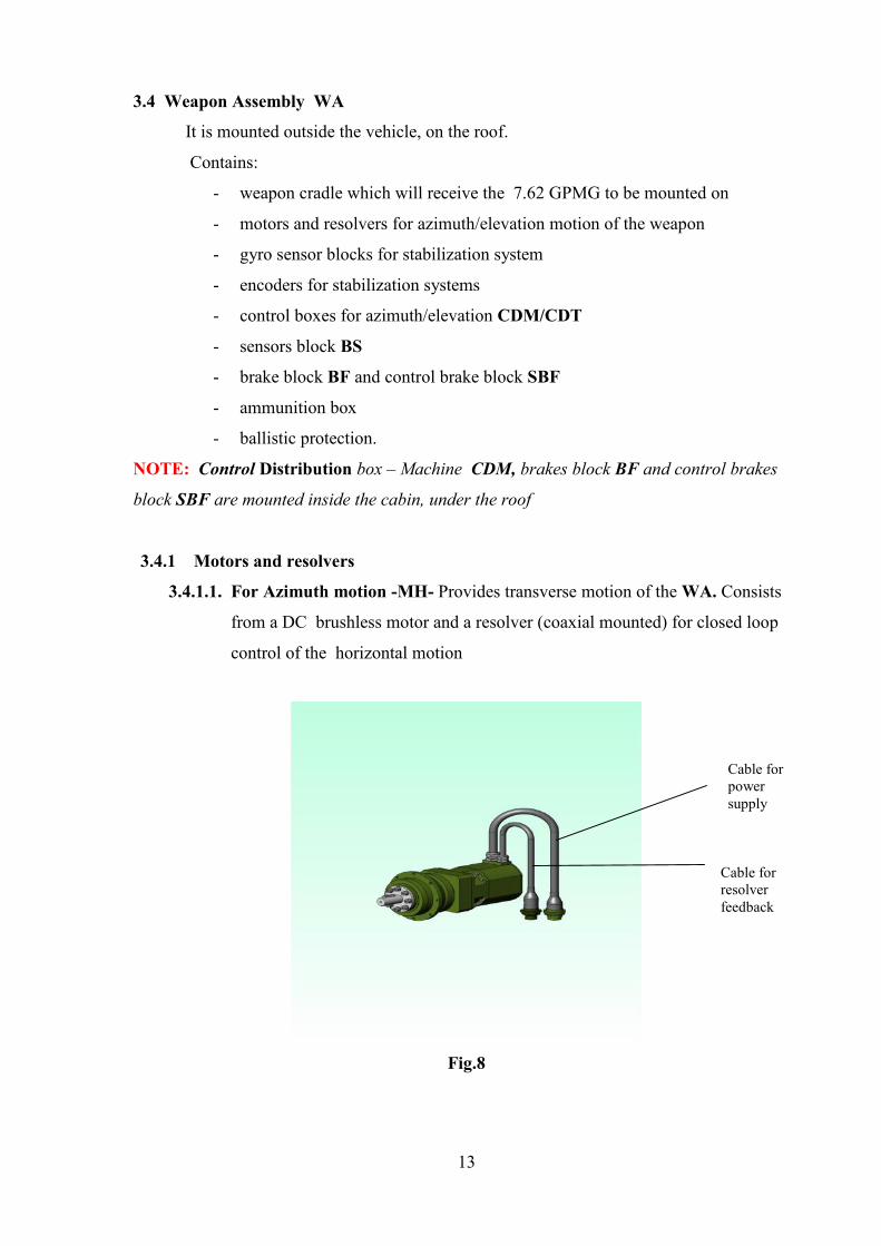
3.4.1 Motors and resolvers
3.4.1.1. For Azimuth motion -MH- Provides transverse motion of the WA. Consists
from a DC brushless motor and a resolver (coaxial mounted) for closed loop
control of the horizontal motion
Fig.8
Cable forpowersupply
Cable forresolverfeedback
14
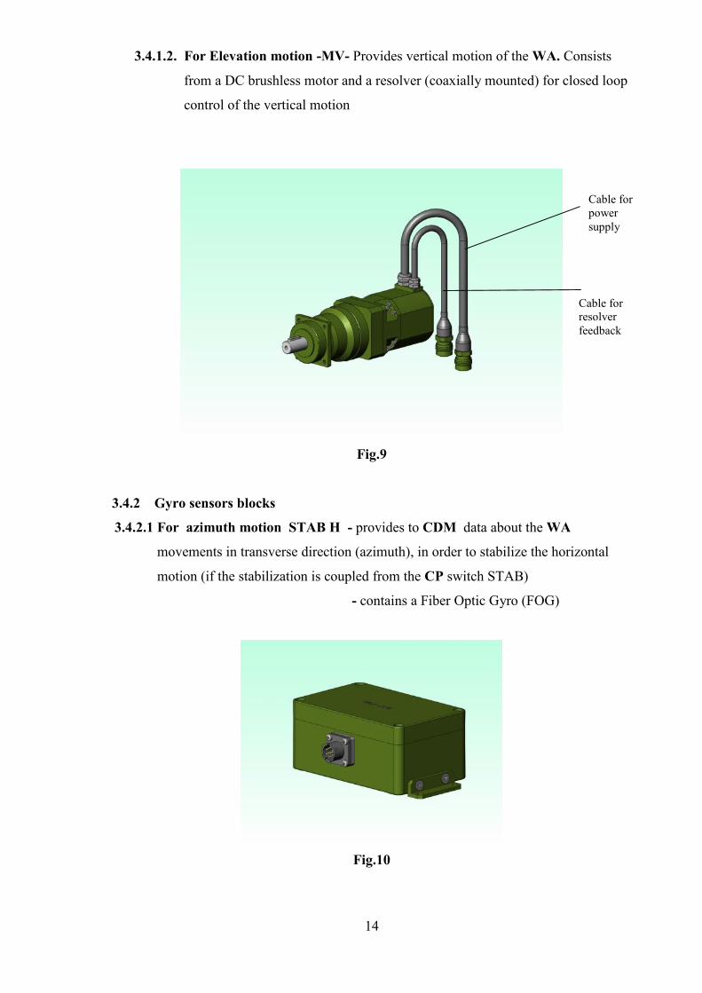
3.4.1.2. For Elevation motion -MV- Provides vertical motion of the WA. Consists
from a DC brushless motor and a resolver (coaxially mounted) for closed loop
control of the vertical motion
Fig.9
3.4.2 Gyro sensors blocks
3.4.2.1 For azimuth motion STAB H - provides to CDM data about the WA
movements in transverse direction (azimuth), in order to stabilize the horizontal
motion (if the stabilization is coupled from the CP switch STAB)
- contains a Fiber Optic Gyro (FOG)
Fig.10
Cable forpowersupply
Cable forresolverfeedback
15
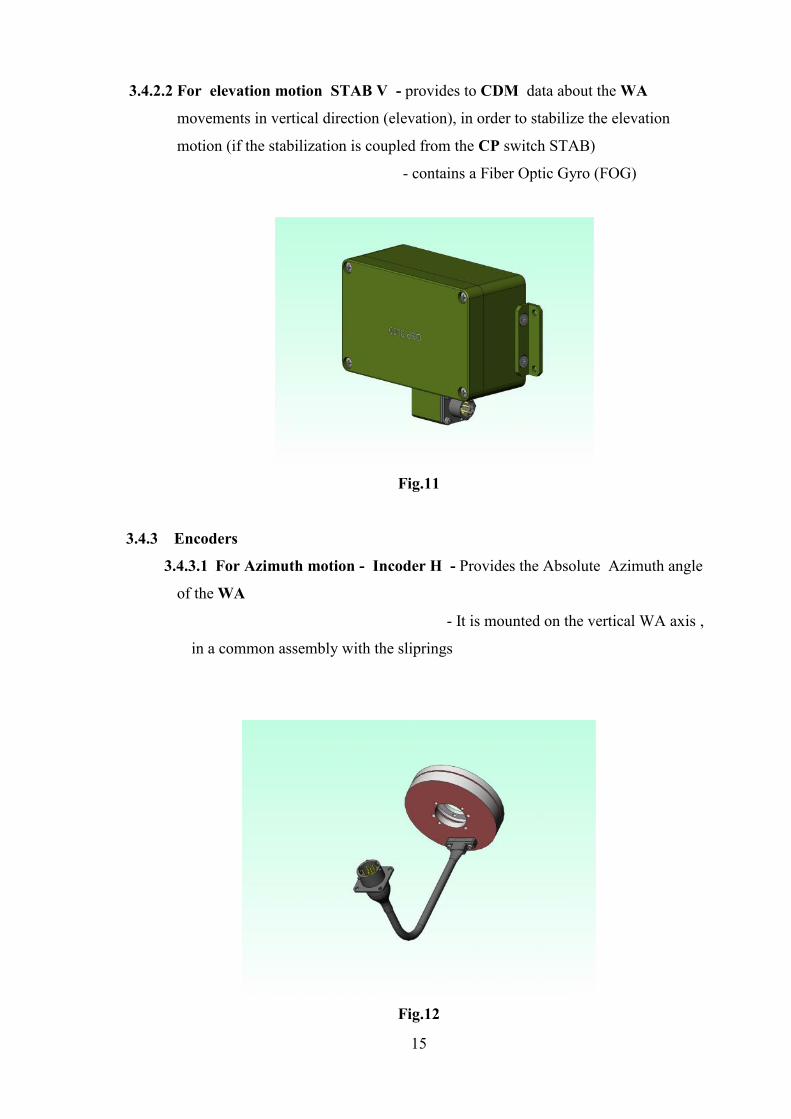
3.4.2.2 For elevation motion STAB V - provides to CDM data about the WA
movements in vertical direction (elevation), in order to stabilize the elevation
motion (if the stabilization is coupled from the CP switch STAB)
- contains a Fiber Optic Gyro (FOG)
Fig.11
3.4.3 Encoders
3.4.3.1 For Azimuth motion - Incoder H - Provides the Absolute Azimuth angle
of the WA
- It is mounted on the vertical WA axis ,
in a common assembly with the sliprings
Fig.12
16
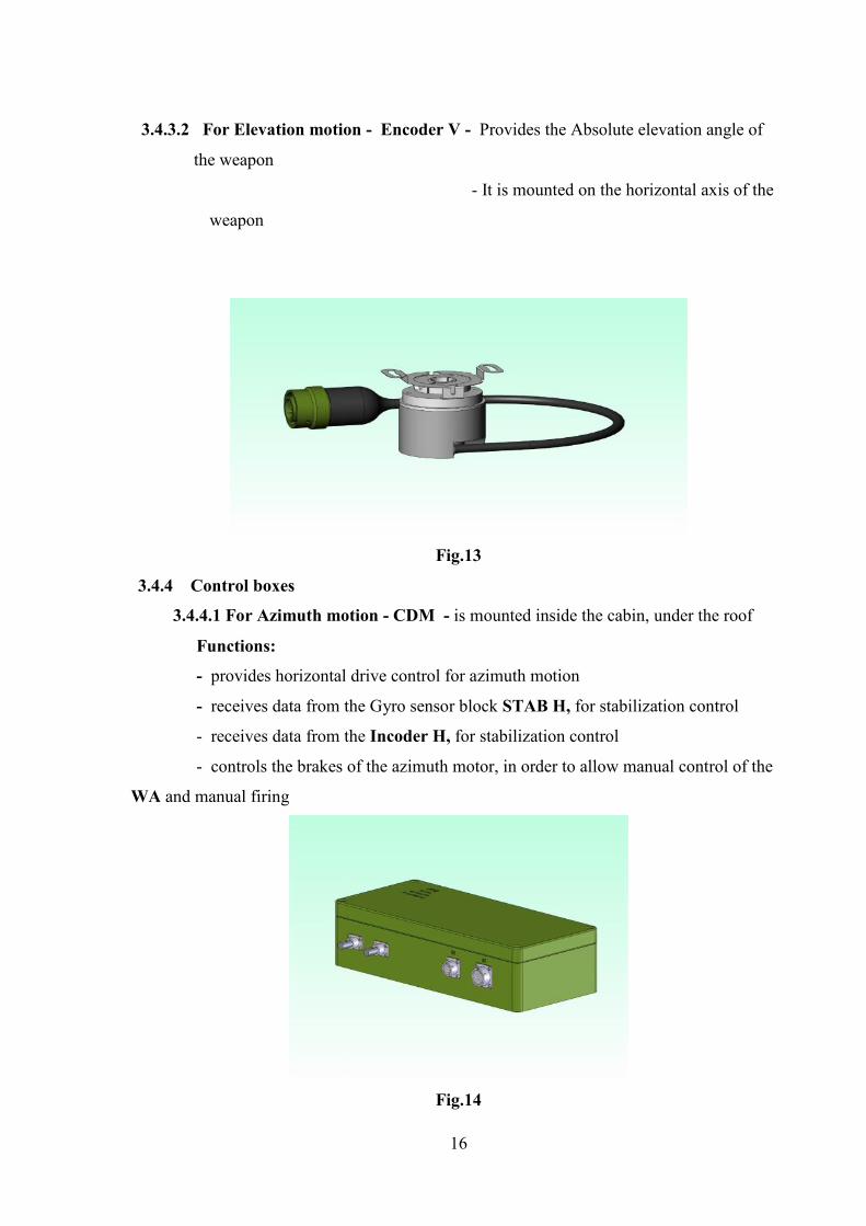
3.4.3.2 For Elevation motion - Encoder V - Provides the Absolute elevation angle of
the weapon
- It is mounted on the horizontal axis of the
weapon
Fig.13
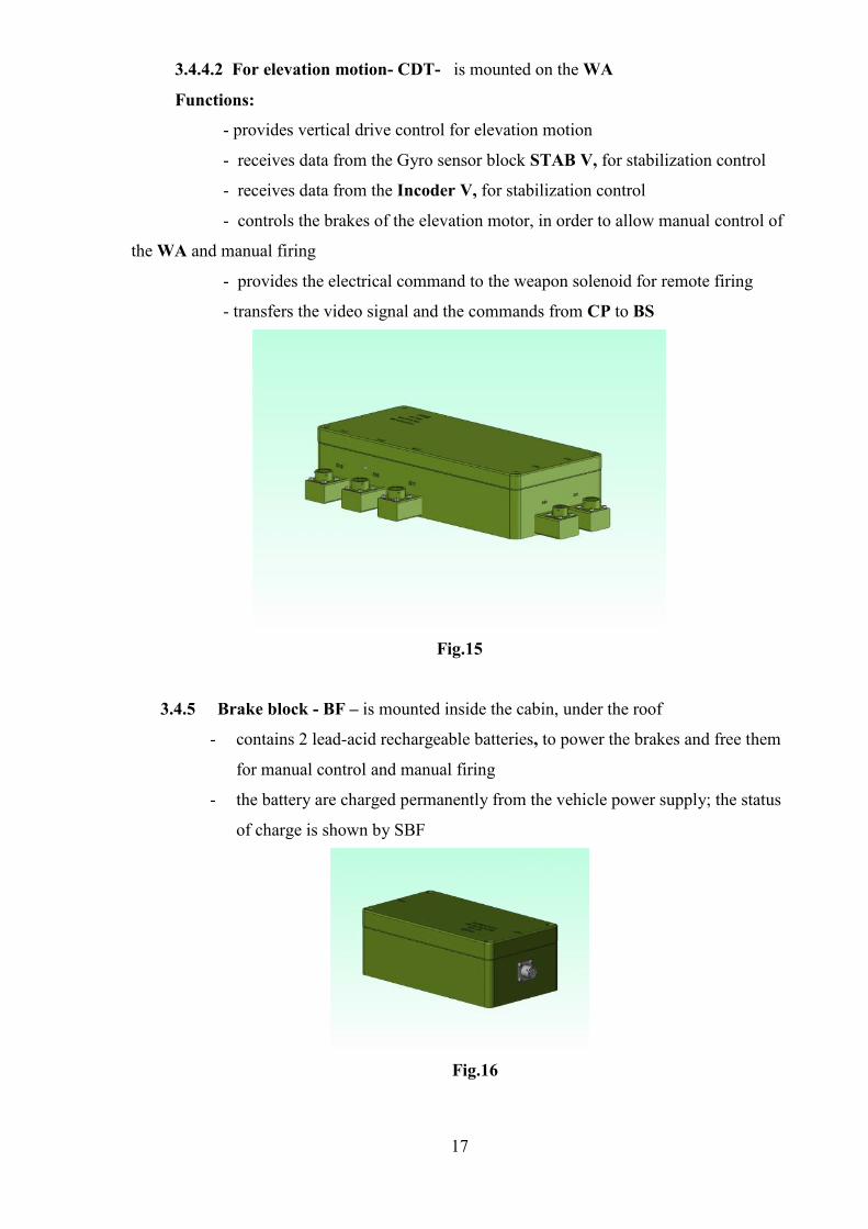
3.4.4 Control boxes
3.4.4.1 For Azimuth motion - CDM - is mounted inside the cabin, under the roof
Functions:
- provides horizontal drive control for azimuth motion
- receives data from the Gyro sensor block STAB H, for stabilization control
- receives data from the Incoder H, for stabilization control
- controls the brakes of the azimuth motor, in order to allow manual control of the
WA and manual firing
Fig.14
17
3.4.4.2 For elevation motion- CDT- is mounted on the WA
Functions:
- provides vertical drive control for elevation motion
- receives data from the Gyro sensor block STAB V, for stabilization control
- receives data from the Incoder V, for stabilization control
- controls the brakes of the elevation motor, in order to allow manual control of
the WA and manual firing
- provides the electrical command to the weapon solenoid for remote firing
- transfers the video signal and the commands from CP to BS
Fig.15
3.4.5 Brake block - BF – is mounted inside the cabin, under the roof
- contains 2 lead-acid rechargeable batteries, to power the brakes and free them
for manual control and manual firing
- the battery are charged permanently from the vehicle power supply; the status
of charge is shown by SBF
Fig.16
18
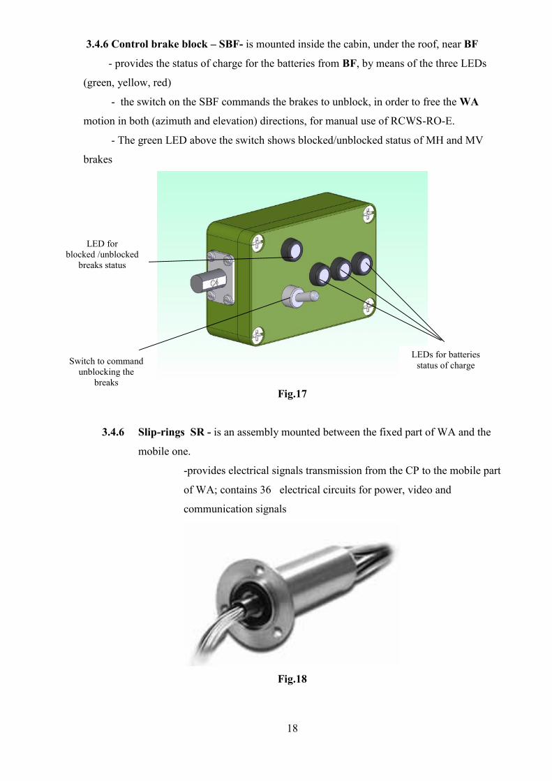
3.4.6 Control brake block – SBF- is mounted inside the cabin, under the roof, near BF
- provides the status of charge for the batteries from BF, by means of the three LEDs
(green, yellow, red)
- the switch on the SBF commands the brakes to unblock, in order to free the WA
motion in both (azimuth and elevation) directions, for manual use of RCWS-RO-E.
- The green LED above the switch shows blocked/unblocked status of MH and MV
brakes
Fig.17
3.4.6 Slip-rings SR - is an assembly mounted between the fixed part of WA and the
mobile one.
-provides electrical signals transmission from the CP to the mobile part
of WA; contains 36 electrical circuits for power, video and
communication signals
Fig.18
LED forblocked /unblocked
breaks status
Switch to commandunblocking the
breaks
LEDs for batteriesstatus of charge
19
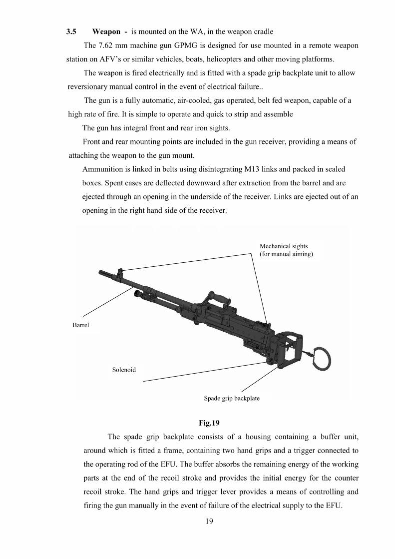
3.5 Weapon - is mounted on the WA, in the weapon cradle
The 7.62 mm machine gun GPMG is designed for use mounted in a remote weapon
station on AFV’s or similar vehicles, boats, helicopters and other moving platforms.
The weapon is fired electrically and is fitted with a spade grip backplate unit to allow
reversionary manual control in the event of electrical failure..
The gun is a fully automatic, air-cooled, gas operated, belt fed weapon, capable of a
high rate of fire. It is simple to operate and quick to strip and assemble
The gun has integral front and rear iron sights.
Front and rear mounting points are included in the gun receiver, providing a means of
attaching the weapon to the gun mount.
Ammunition is linked in belts using disintegrating M13 links and packed in sealed
boxes. Spent cases are deflected downward after extraction from the barrel and are
ejected through an opening in the underside of the receiver. Links are ejected out of an
opening in the right hand side of the receiver.
Fig.19
The spade grip backplate consists of a housing containing a buffer unit,
around which is fitted a frame, containing two hand grips and a trigger connected to
the operating rod of the EFU. The buffer absorbs the remaining energy of the working
parts at the end of the recoil stroke and provides the initial energy for the counter
recoil stroke. The hand grips and trigger lever provides a means of controlling and
firing the gun manually in the event of failure of the electrical supply to the EFU.
Spade grip backplate
Barrel
Mechanical sights(for manual aiming)
Solenoid
20
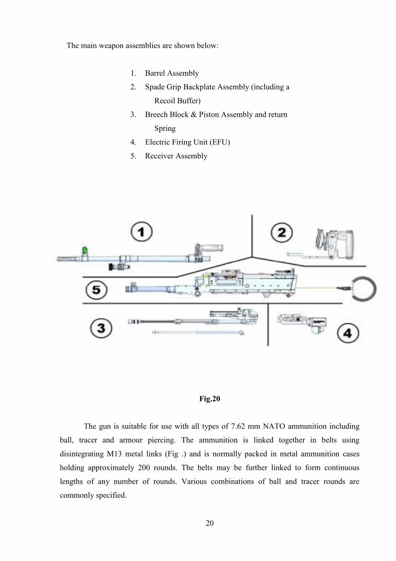
The main weapon assemblies are shown below:
1. Barrel Assembly
2. Spade Grip Backplate Assembly (including a
Recoil Buffer)
3. Breech Block & Piston Assembly and return
Spring
4. Electric Firing Unit (EFU)
5. Receiver Assembly
Fig.20
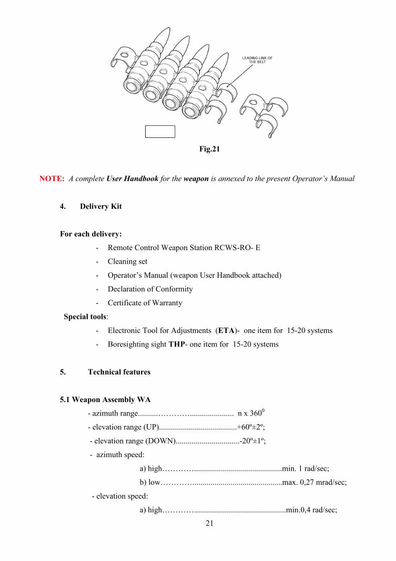
The gun is suitable for use with all types of 7.62 mm NATO ammunition including
ball, tracer and armour piercing. The ammunition is linked together in belts using
disintegrating M13 metal links (Fig .) and is normally packed in metal ammunition cases
holding approximately 200 rounds. The belts may be further linked to form continuous
lengths of any number of rounds. Various combinations of ball and tracer rounds are
commonly specified.
21
Fig.21
NOTE: A complete User Handbook for the weapon is annexed to the present Operator’s Manual
4. Delivery Kit
For each delivery:
- Remote Control Weapon Station RCWS-RO- E
- Cleaning set
- Operator’s Manual (weapon User Handbook attached)
- Declaration of Conformity
- Certificate of Warranty
Special tools:
- Electronic Tool for Adjustments (ETA)- one item for 15-20 systems
- Boresighting sight THP- one item for 15-20 systems
5. Technical features
5.1 Weapon Assembly WA
- azimuth range..........…………...................... n x 3600
- elevation range (UP).......................................+60º±2º;
- elevation range (DOWN)................................-20º±1º;
- azimuth speed:
a) high…………............................................min. 1 rad/sec;
b) low………….............................................max. 0,27 mrad/sec;
- elevation speed:
a) high…………..............................................min.0,4 rad/sec;

22
b) low…………..............................................max. 0,27 mrad/sec;
- The weapon is stabilised in the inertial reference frame to an accuracy of
1.0 mRad RMS in both axes while the vehicle is moving 24 km/h over a smooth gravel
road.
- operating voltage …………..........................18÷ 32Vcc;
- power consumption (average)…………..........max.7 A;
- power consumption (max 1 sec.)......................max.25 A;
- weight (without gun and ammunition)............ max. 165 Kg
- overall dimensions........................................... max.849x671x602 mm
- environmental conditions.................................MIL STD 810 F
- ballistic protection ………………………. level 3 against 7.62 ammunition
5.2 Sensors block BS
5.2.1 Thermal camera TC
- type.............................................uncooled
- spectral range................................8 ÷ 12 μm
- microbolometer matrix.......…… min.640x480 pixels;
- lens focal distance................……45/135 mm ;
- two FOVs................................... min.12,6°x9,4°(H) and 4,10x30(V)
- digital zoom.................................2x
- detection range (man target) .......min 2500m
- video output..................................video composite CCIR
5.2.2 Day CCD camera DC
- senzor…………................................1/4 inch CCD
- pixels……………..............................min. 440 000
-rezolution……………......... .............min 460 TV lines
- FOV....................................................min. 1.6° to 42.2° (H)
- S/N ratio………...………....................min 50 dB
- lens………………............................optical zoom, min 26x;
- detection range (man target) ............min 8500m
- interface...........………………..........RS 232 /485
- supply voltage..............…...…..........12 V cc
- video output..................................video composite CCIR
5.3 Display DIS
23
- size.......................................10,4"
- input......................................VGA/PAL – composite video
- resolution...............................800X600 pixels
- overlay PCB...........................letters and symbols
- supply voltage....................... 18÷ 32Vcc
- environmental conditions......according military standards
5.4 Weapon
Calibre ....................................... 7.62 mm
Length (extended butt)........... 1120 mm (44”)
Weight
(1) Gun (with barrel) ...........13.6 kg (30 lb)
(2) Barrel ................................2.83 kg (6 lb)
Length of barrel.........................679 mm (26.75”)
No. of grooves...........................4
Pitch of rifling...........................1 in 305 mm (right hand)
System of operation .....................Gas with recoil buffer & return spring
assistance
Rate of fire..................................650 – 950 rpm
Sights: ............................Fixed foresight
Rearsight, aperture graduated in steps of 100m
Folded down ................................200 to 800 metres
Raised ...........................................800 to 1800 metres
6. Safety rules
Several safety aspects have been introduced in order to offer a complete
safe-to-use system under normal operational conditions and within the operational
guidelines.
The RCWS-RO-E system is used from the safety of a vehicle and
personnel are not required outside the vehicle to aim or fire the weapon.
(only in case of electrical failure, the system may be controlled manually)
The weapon trigger switch is situated on the left of the CP, behind a safety
flap to prevent accidental activation.
24
Before the weapon can be commanded to fire, several operations must be
performed:
-The „operating” mode must be switched from „Observation”, first to „target
acquisition”. Now the stadia scale allow to estimate the distance to the target
- The firing mode is selected by pressing the button of the joystick; and the firing
reticle is available and the aiming is performed
- The „Fire type” selector must be switched from „0” to „ single shot”, „short burst”
or „long burst”
- The FIRE switch flap must be removed
- The Fire switch must be turned „ON”
The firing can be performed ONLY after these 5 succesive operations !
The CP incorporates a Gunner Grip (dead man switch) to prevent the
turret from moving when the Joystick is accidentally moved while the turret
is enabled.
A hatch open sensor is monitored to disable turret movement and firing
of the weapon while the hatch is open. The override on the CP can be used
to override the hatches open state in the event where the hatches open sensor
is faulty and prevents normal weapon system operation.
Safe operation with the gun : the procedures for loading, unloading and
clearing the gun, firing and firing precautions, causes and actions for dealing
with stoppages are described in User Handbook for GPMG 7.62, which is an
annex to the present Manual
7. Mounting and operating instructions
All the components of the RCWS-RO-E system are mounted on the locations destined for
observation and firing. No additional operations for positioning or adjustments are necessary
7.1 Preliminary checking
- check the Delivery kit
- check the operator’s working post: Seat, Control Panel, Display
- check the WA mounting and the gun mounting on WA
- check the ammunition box mounting and the gun feeding
- check the cocking mechanism
- check the BF batteries status of charge - on the SBF box under the roof
- check the general aspect of the subsystems (no hits, no exfoliations, no corrosion)

25
7.2- Starting the system
NOTE the system can be electrically (remotely) operated only if the hatch is closed !
After closing the hatch, put the SYS switch to ON position.
The system becomes a self testing procedure (BIT):
- The LEDs CDM, CDT, BS STB light green for 0.5 sec, then light red for 0.5 sec, than
remain off for 0.5 sec and finally light according each status of the subsystem
- The led on DIS lights green for 0.5 sec, then lights red for 0.5 sec, than remains off for 0.5
sec and finally light according DIS status.
- During BIT, the screen displays „SELFTEST – Please wait” while DIS is self tested,
then „SYSTEM TEST – Please wait” during the self test for all the subsystems
- After BIT is finished, the Observation Mode screen is dysplayed as default
a) All the 6 LEDs on the CP must light as follows:
SYS –green- all the subsystems are powered from the vehicle voltage supply
CDM, CDT, BS – green- these subsystems are working properly (if the LED is blinking
green the BIT/ initialization is performed)
– green, if the STAB switch is ON, no light if STAB switch is OFF
BRK- no light – it will be lit red if the brakes are released (the switch on SBF is ON)
If:
- CDM, CDT, BS, are red or are blinking red, there is an error in the system ( subsystem
failure or no communication)
- STB is red if the stabilization is coupled but there is an error
- BRK is red, the brakes are released and the WA may be operated manually
b) the display DIS is powered and an image of the external viewed objects, transmitted by BS
optical sensors, appears on the screen
NOTE If the chosen camera is TC, the image might appear after 30-40 sec. delay, because
of the thermal sensor initialing
26
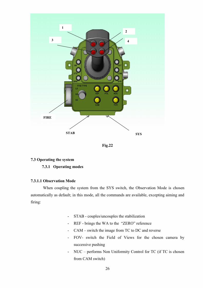
Fig.22
7.3 Operating the system
7.3.1 Operating modes
7.3.1.1 Observation Mode
When coupling the system from the SYS switch, the Observation Mode is chosen
automatically as default; in this mode, all the commands are available, excepting aiming and
firing:
- STAB - couples/uncouples the stabilization
- REF - brings the WA to the “ZERO” reference
- CAM – switch the image from TC to DC and reverse
- FOV- switch the Field of Views for the chosen camera by
successive pushing
- NUC – performs Non Uniformity Control for TC (if TC is chosen
from CAM switch)
SYSSTAB
FIRE
2
4
1
3
27
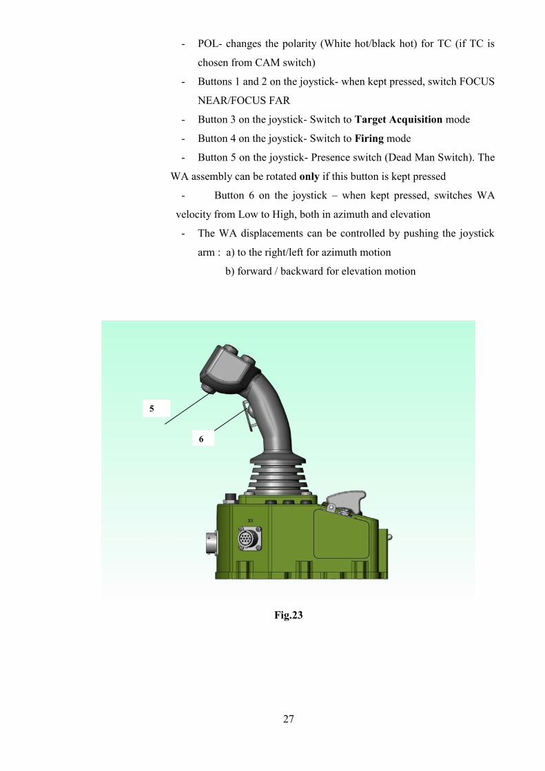
- POL- changes the polarity (White hot/black hot) for TC (if TC is
chosen from CAM switch)
- Buttons 1 and 2 on the joystick- when kept pressed, switch FOCUS
NEAR/FOCUS FAR
- Button 3 on the joystick- Switch to Target Acquisition mode
- Button 4 on the joystick- Switch to Firing mode
- Button 5 on the joystick- Presence switch (Dead Man Switch). The
WA assembly can be rotated only if this button is kept pressed
- Button 6 on the joystick – when kept pressed, switches WA
velocity from Low to High, both in azimuth and elevation
- The WA displacements can be controlled by pushing the joystick
arm : a) to the right/left for azimuth motion
b) forward / backward for elevation motion
Fig.23
5
6
28
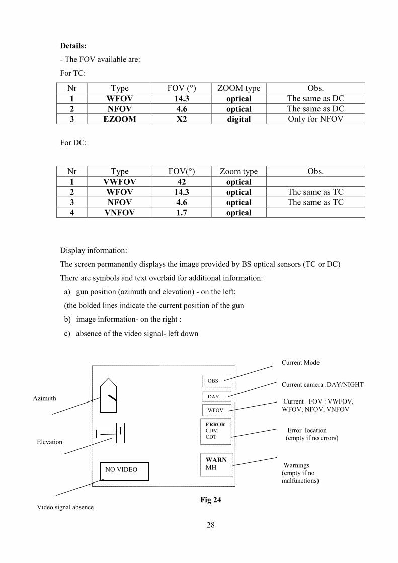
Details:
- The FOV available are:
For TC:
Nr Type FOV (°) ZOOM type Obs.1 WFOV 14.3 optical The same as DC2 NFOV 4.6 optical The same as DC3 EZOOM X2 digital Only for NFOV
For DC:
Nr Type FOV(°) Zoom type Obs.1 VWFOV 42 optical2 WFOV 14.3 optical The same as TC3 NFOV 4.6 optical The same as TC4 VNFOV 1.7 optical
Display information:
The screen permanently displays the image provided by BS optical sensors (TC or DC)
There are symbols and text overlaid for additional information:
a) gun position (azimuth and elevation) - on the left:
(the bolded lines indicate the current position of the gun
b) image information- on the right :
c) absence of the video signal- left down
Fig 24
OBS
DAY
WFOV
Current Mode
Current camera :DAY/NIGHT
Current FOV : VWFOV,WFOV, NFOV, VNFOV
Error location(empty if no errors)
Warnings(empty if nomalfunctions)
ERRORCDMCDT
WARNMH
Azimuth
Elevation
NO VIDEO
Video signal absence
29
ERROR – indicates the subsystems which is failed or has no communication with CP
WARN - provides a warning message for:
- in operation modes- Subsystems which have a function problem
(ex. the temperature becomes too high-MH, power supply is under
22 V)
- in auxiliary modes: - function not set yet, but which needs to be
set (ex. LIM needs to be set after REF has been set) - after LIM is
set, the warning disappears
One may leave the Observation Mode:
- switching to Target Acquisition Mode (button 3 on the Joystick)
- switching to Firing Mode (button 4 on the joystick)
- switching to an auxiliary mode (see chapter 7.3.2)
7.3.1.2 Target Acquisition mode
This mode is available, from Observation Mode, by pushing the button 3 on the
joystick arm. In this case, the NFOV is automatically selected, in order to have an optimal
image of the target (maximum optical zoom) .
This mode is destined to estimate the distance to the target in order to aim correctly
for an accurate shot
In this mode, the following commands are available (fig.23, fig.24):
- STAB - couples/uncouples the stabilization
- REF - brings the WA to the “ZERO” reference
- CAM – switch the image from TC to DC and reverse
- FOV- switch to the Observation Mode ; the FOV for the current
camera switches in the next one available
- NUC – performs Non Uniformity Control for TC (if TC is chosen
from CAM switch)
- POL- changes the polarity (White hot/black hot) for TC (if TC is
chosen from CAM switch)
- Buttons 1 and 2 on the joystick- when kept pressed, switch FOCUS
NEAR/FOCUS FAR
- Button 3 on the joystick- Switch to Observation mode
- Button 4 on the joystick- Switch to Firing mode
30
- Button 5 on the joystick- Presence switch (Dead Man Switch). The
WA assembly can be rotated only if this button is kept pressed
- Button 6 on the joystick – when kept pressed, switches WA
velocity from Low to High, both in azimuth and elevation
- The WA displacements can be controlled by pushing the joystick
arm : a) to the right/left for azimuth motion
d) forward / backward for elevation motion
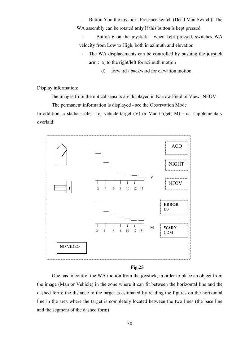
Display information:
The images from the optical sensors are displayed in Narrow Field of View- NFOV
The permanent information is displayed - see the Observation Mode
In addition, a stadia scale - for vehicle-target (V) or Man-target( M) - is supplementary
overlaid:
Fig.25
One has to control the WA motion from the joystick, in order to place an object from
the image (Man or Vehicle) in the zone where it can fit between the horizontal line and the
dashed form; the distance to the target is estimated by reading the figures on the horizontal
line in the area where the target is completely located between the two lines (the base line
and the segment of the dashed form)
NIGHT
ACQ
NFOV
ERRORBS
WARNCDM
2 4 6 8 10 12 15
2 4 6 8 10 12 15
V
M
NIGHT
ACQ
NFOV
ERRORBS
WARNCDM
NO VIDEO
31
One may leave the Target Acquisition Mode:
- switching to Observation Mode (button 3 on the Joystick or FOV
button)
- switching to Firing Mode (button 4 on the joystick)
- switching to an auxiliary mode (see chapter 7.3.2)
7.3.1.3 Firing mode
This mode is available from Observation Mode or from Target Acquisition Mode
by pushing the button 4 on the joystick arm.
In this case, the NFOV is automatically selected, in order to have an optimal image
of the target (maximum optical zoom)
This mode is destined to aim the target before shooting. An aiming reticle is
displayed on the screen
In this mode, the following commands are available (fig.23, fig.24):
- STAB - couples/uncouples the stabilization
- FIRE TYPE – a rotary switch; one may choose the followings
types of shots : Single Shot SS, Short Burst SB or Long Burst LB
- FIRE – protected switch - which can be operated if FIRE TYPE
rotary switch is positioned on one of the three options: SS, SB or
LB
- REF - brings the WA to the “ZERO” reference
- CAM – switch the image from TC to DC and reverse
- FOV- switch to the Observation Mode ; the FOV for the current
camera switches in the next one available
- NUC – performs Non Uniformity Control for TC (if TC is chosen
from CAM switch)
- POL- changes the polarity (White hot/black hot) for TC (if TC is
chosen from CAM switch)
- Buttons 1 and 2 on the joystick- when kept pressed, switch FOCUS
NEAR/FOCUS FAR
- Button 3 on the joystick- Switch to Target Acquisition mode
- Button 4 on the joystick- Switch to Observation mode
- Button 5 on the joystick- Presence switch (Dead Man Switch). The
WA assembly can be rotated only if this button is kept pressed
32
- Button 6 on the joystick – when kept pressed, switches WA
velocity from Low to High, both in azimuth and elevation
- The WA displacements can be controlled by pushing the joystick
arm : a) to the right/left for azimuth motion
e) forward / backward for elevation motion
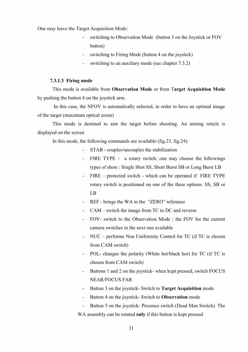
Display information:
The images from the optical sensors are displayed in Narrow Field of View- NFOV
The permanent information is displayed - see the Observation Mode
In addition, an aiming reticle is supplementary overlaid:
Fig.26
The distances estimated in Target Acquisition Mode are used for aiming. The gunner
has to superpose the line of the aiming reticle corresponding to the distance to target,
measured on the stadia scale , on the target to be shot. It means that the elevating angle of the
weapon is adjusted according to the type of target and to the estimated range to target.
When all the safety conditions for starting the fire are fulfilled, a message SS (SB,
LB) FIRE READY is displayed on the bottom of the screen, depending on the fire type. This
message will last as long as the safety fire conditions last (see chapter 6).
The FIRE switch can be pushed now, after removing the protection flap
One may leave the Firing Mode:
2
4
6
8
10
12
15
FIRE
DAY
NFOV
ERRORMV
SS FIRE READYWARN
MH
“Fire Ready“message
NO VIDEO
33
- switching to Observation Mode (button 4 on the Joystick or FOV
button)
- switching to Target Acquisition Mode (button 3 on the joystick)
- switching to an auxiliary mode (see chapter 7.3.2)
7.3.2 Auxiliary modes
These modes are not available for the operators. They are destined for maintenance
personnel who might need to perform some settings and adjustments periodically or at
request.
A special tool ETA is provided for this purpose. This special electronic tool must be
connected to the CP (X1 panel connector)
7.3.2.1 –Boresighting the gun with BS sensors
- The rotary switch on ETA is put on ALIGN position
- The FOV is automatically switched to NFOV
- A special reticle (crosshair) is generated by DIS
a) Method 1
- A panel with three cross-marks, situated at 25 m distance from the gun, is used. The
distance between the three cross-marks depends upon the distance between the gun axis, the
TC optical axis and DC optical axis which should be convergent at 800-1000m.
- The height of the gun mark on the panel shall be the same as the gun height on the vehicle
- A laser pointer is mounted in the gun barrel; move the WA, so the laser point on the panel
to be superposed on the gun mark on the same panel
- Move the cross-hair reticle (by pushing the 1,2,3,4 buttons on the joystick arm) for each
camera (TC and DC) so to be superposed respectively to the TC an DC marks on the panel
- The position is stored by pushing and keeping pushed REF button more than 2 seconds
- Now, the boresighting is finished and stored
b) Method 2
- A thin object is chosen at a 1000 m distance (ex: an antenna , a building edge)
- A THP sight (provided as a special tool) is mounted in the gun barrel
- The thin object chosen is aimed by the THP, rotating the WA in azimuth/elevation
- Move the cross-hair reticle (by pushing the 1,2,3,4 buttons on the joystick arm) for each
camera (TC and DC) so to aim the same thin object
- The position is stored by pushing and keeping pushed REF button more than 2 seconds
34
- Now, the boresighting is finished and stored
NOTE The buttons STAB, FOV are inactive
The button REF has a storage function
The buttons 1,2,3,4 on the Joystick arm are used to move the cross-hair for cameras
in order to perform boresighting. Their functions are different in this Boresighting mode
with respect to Operating modes
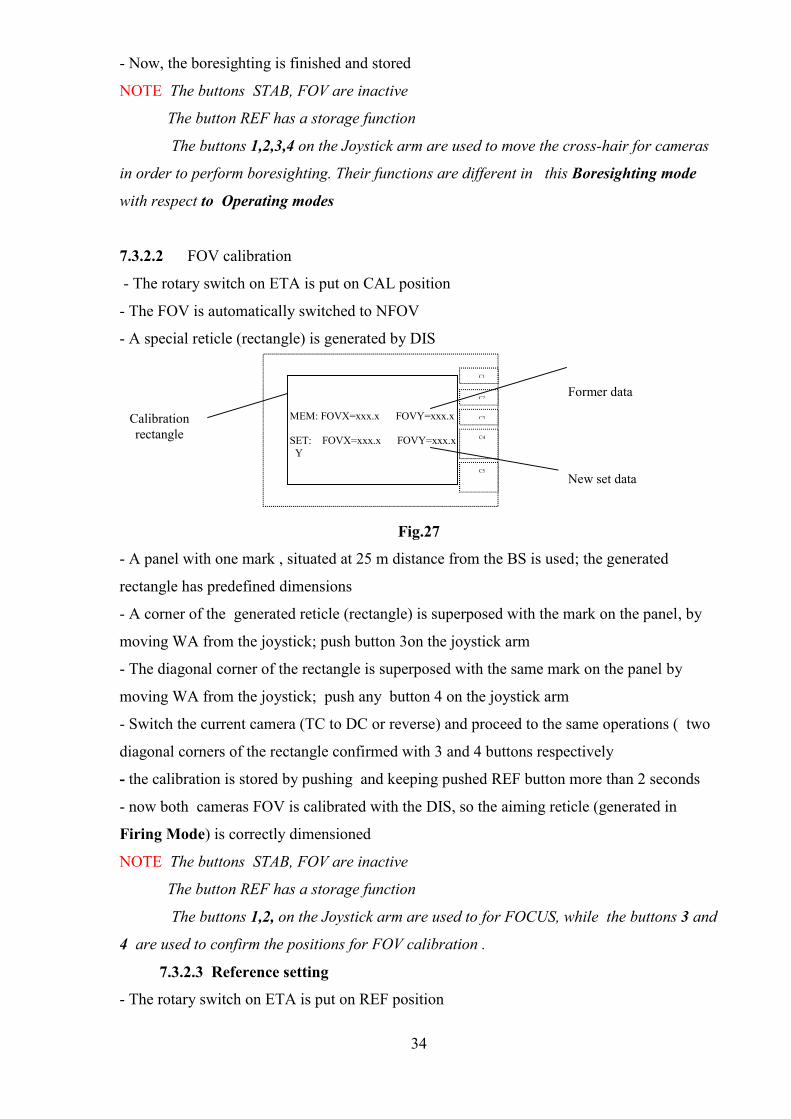
7.3.2.2 FOV calibration
- The rotary switch on ETA is put on CAL position
- The FOV is automatically switched to NFOV
- A special reticle (rectangle) is generated by DIS
Fig.27
- A panel with one mark , situated at 25 m distance from the BS is used; the generated
rectangle has predefined dimensions
- A corner of the generated reticle (rectangle) is superposed with the mark on the panel, by
moving WA from the joystick; push button 3on the joystick arm
- The diagonal corner of the rectangle is superposed with the same mark on the panel by
moving WA from the joystick; push any button 4 on the joystick arm
- Switch the current camera (TC to DC or reverse) and proceed to the same operations ( two
diagonal corners of the rectangle confirmed with 3 and 4 buttons respectively
- the calibration is stored by pushing and keeping pushed REF button more than 2 seconds
- now both cameras FOV is calibrated with the DIS, so the aiming reticle (generated in
Firing Mode) is correctly dimensioned
NOTE The buttons STAB, FOV are inactive
The button REF has a storage function
The buttons 1,2, on the Joystick arm are used to for FOCUS, while the buttons 3 and
4 are used to confirm the positions for FOV calibration .
7.3.2.3 Reference setting
- The rotary switch on ETA is put on REF position
MEM: FOVX=xxx.x FOVY=xxx.x
SET: FOVX=xxx.x FOVY=xxx.x Y
C1
C2
C3
C4
C5
Calibrationrectangle
Former data
New set data
35
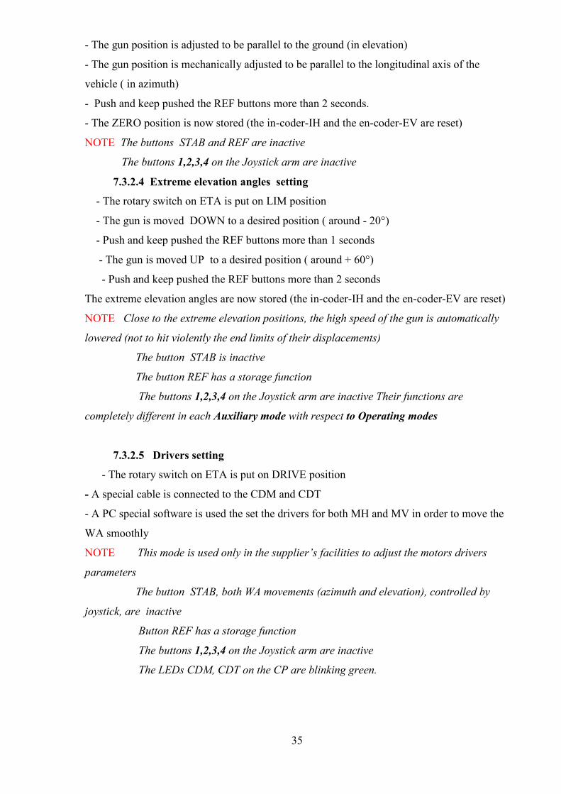
- The gun position is adjusted to be parallel to the ground (in elevation)
- The gun position is mechanically adjusted to be parallel to the longitudinal axis of the
vehicle ( in azimuth)
- Push and keep pushed the REF buttons more than 2 seconds.
- The ZERO position is now stored (the in-coder-IH and the en-coder-EV are reset)
NOTE The buttons STAB and REF are inactive
The buttons 1,2,3,4 on the Joystick arm are inactive
7.3.2.4 Extreme elevation angles setting
- The rotary switch on ETA is put on LIM position
- The gun is moved DOWN to a desired position ( around - 20°)
- Push and keep pushed the REF buttons more than 1 seconds
- The gun is moved UP to a desired position ( around + 60°)
- Push and keep pushed the REF buttons more than 2 seconds
The extreme elevation angles are now stored (the in-coder-IH and the en-coder-EV are reset)
NOTE Close to the extreme elevation positions, the high speed of the gun is automatically
lowered (not to hit violently the end limits of their displacements)
The button STAB is inactive
The button REF has a storage function
The buttons 1,2,3,4 on the Joystick arm are inactive Their functions are
completely different in each Auxiliary mode with respect to Operating modes
7.3.2.5 Drivers setting
- The rotary switch on ETA is put on DRIVE position
- A special cable is connected to the CDM and CDT
- A PC special software is used the set the drivers for both MH and MV in order to move the
WA smoothly
NOTE This mode is used only in the supplier’s facilities to adjust the motors drivers
parameters
The button STAB, both WA movements (azimuth and elevation), controlled by
joystick, are inactive
Button REF has a storage function
The buttons 1,2,3,4 on the Joystick arm are inactive
The LEDs CDM, CDT on the CP are blinking green.
36
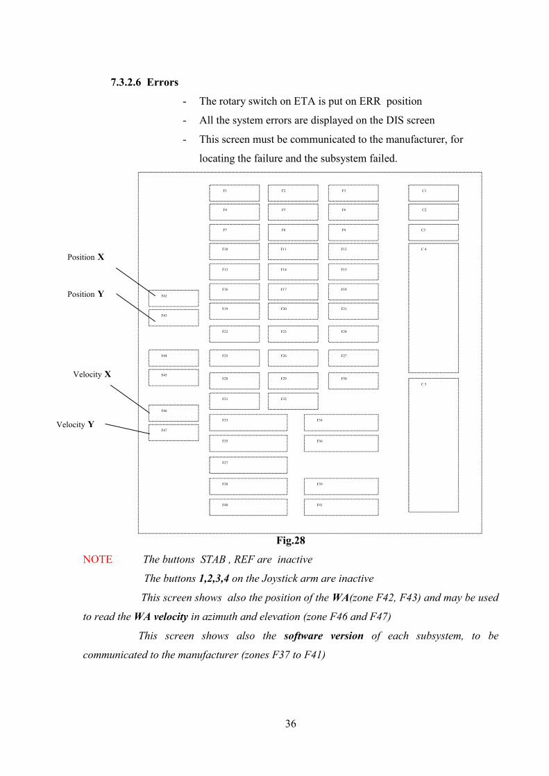
7.3.2.6 Errors
- The rotary switch on ETA is put on ERR position
- All the system errors are displayed on the DIS screen
- This screen must be communicated to the manufacturer, for
locating the failure and the subsystem failed.
Fig.28
NOTE The buttons STAB , REF are inactive
The buttons 1,2,3,4 on the Joystick arm are inactive
This screen shows also the position of the WA(zone F42, F43) and may be used
to read the WA velocity in azimuth and elevation (zone F46 and F47)
This screen shows also the software version of each subsystem, to be
communicated to the manufacturer (zones F37 to F41)
C1
C2
C3
C 4
F1 F2
F4 F5
F7 F8
F10 F11
F13
F33 F34
F19
C 5
F3
F6
F9
F12
F14 F15
F20 F21
F22 F24 F23
F25 F26 F27
F28 F30 F29
F31
F16 F17 F18
F35 F36
F37
F38 F39
F40 F41
F32
F42
F43
F44
F45
F46
F47
Velocity X
Velocity Y
Position X
Position Y
37
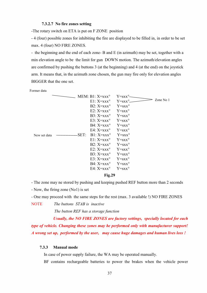
7.3.2.7 No fire zones setting
-The rotary switch on ETA is put on F ZONE position
- 4 (four) possible zones for inhibiting the fire are displayed to be filled in, in order to be set
max. 4 (four) NO FIRE ZONES.
- the beginning and the end of each zone- B and E (in azimuth) may be set, together with a
min elevation angle to be the limit for gun DOWN motion. The azimuth/elevation angles
are confirmed by pushing the buttons 3 (at the beginning) and 4 (at the end) on the joystick
arm. It means that, in the azimuth zone chosen, the gun may fire only for elevation angles
BIGGER that the one set.
Fig.29
- The zone may ne stored by pushing and keeping pushed REF button more than 2 seconds
- Now, the firing zone (No1) is set
- One may proceed with the same steps for the rest (max. 3 available !) NO FIRE ZONES
NOTE The buttons STAB is inactive
The button REF has a storage function
Usually, the NO FIRE ZONES are factory settings, specially located for each
type of vehicle. Changing these zones may be performed only with manufacturer support!
A wrong set up, performed by the user, may cause huge damages and human lives loss !
7.3.3 Manual mode
In case of power supply failure, the WA may be operated manually.
BF contains rechargeable batteries to power the brakes when the vehicle power
MEM: B1: X=xxx° Y=sxx° E1: X=xxx° Y=sxx°
B2: X=xxx° Y=sxx° E2: X=xxx° Y=sxx° B3: X=xxx° Y=sxx° E3: X=xxx° Y=sxx° B4: X=xxx° Y=sxx° E4: X=xxx° Y=sxx°SET: B1: X=xxx° Y=sxx° E1: X=xxx° Y=sxx°
B2: X=xxx° Y=sxx° E2: X=xxx° Y=sxx° B3: X=xxx° Y=sxx° E3: X=xxx° Y=sxx° B4: X=xxx° Y=sxx° E4: X=xxx° Y=sxx°
New set data
Former data
Zone No 1
38
supply is off
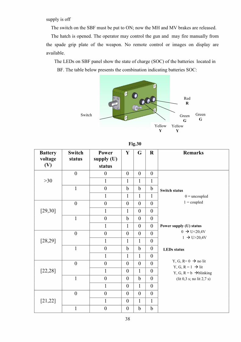
The switch on the SBF must be put to ON; now the MH and MV brakes are released.
The hatch is opened. The operator may control the gun and may fire manually from
the spade grip plate of the weapon. No remote control or images on display are
available.
The LEDs on SBF panel show the state of charge (SOC) of the batteries located in
BF. The table below presents the combination indicating batteries SOC:
Fig.30
Batteryvoltage
(V)
Switchstatus
Powersupply (U)
status
Y G R Remarks
0 0 0 001 1 1 10 b b b
>301
1 1 1 10 0 0 001 1 0 00 b 0 0
[29,30]1
1 1 0 00 0 0 001 1 1 00 b b 0
[28,29]1
1 1 1 00 0 0 001 0 1 00 0 b 0
[22,28]1
1 0 1 00 0 0 001 0 1 1[21,22]
1 0 0 b b
Switch status0 = uncoupled
1 = coupled
Power supply (U) status0 U<20,4V
1 U>20,4V
LEDs status
Y, G, R= 0 no lit Y, G, R = 1 lit
Y, G, R = b blinking(lit 0,3 s; no lit 2,7 s)
Switch
YellowY
GreenG
RedR
GreenG
YellowY
39
1 0 1 10 0 0 001 0 0 10 0 0 b
<211
1 0 0 1
NOTE: If the BF batteries voltage is under 21V, the manual mode cannot be used,
even if the switch is ON
- If the vehicle power supply voltage is under 20.4 V (or is switched off) the
brakes are powered from BF
- The batteries from BF are permanently charged from the vehicle power
supply , between 20.4V and 30 V.
-if the vehicle power supply voltage is more than 30 V, the battery charging is
stopped (overcharge protection)
8. Maintenance
All the subsystems of the RCWS-RO-E are sealed and require no special maintenance
operations.
8.1 Preventive maintenance to the user is limited to:
- visual inspection;
- outside cleaning BS; inside cleaning CP and DIS
- gun cleaning (according GPMG 7.62 User Handbook)
- operational check
- replacing damaged or lost parts with spare parts procured from the manufacturer.
These activities shall be performed:
at start-up
after a repair
prior to and after a mission
periodically (if the device has not been used):
monthly: visual inspection and cleaning
every 3 months: operational check
every 3 years: checking and replacing the rubber parts
40
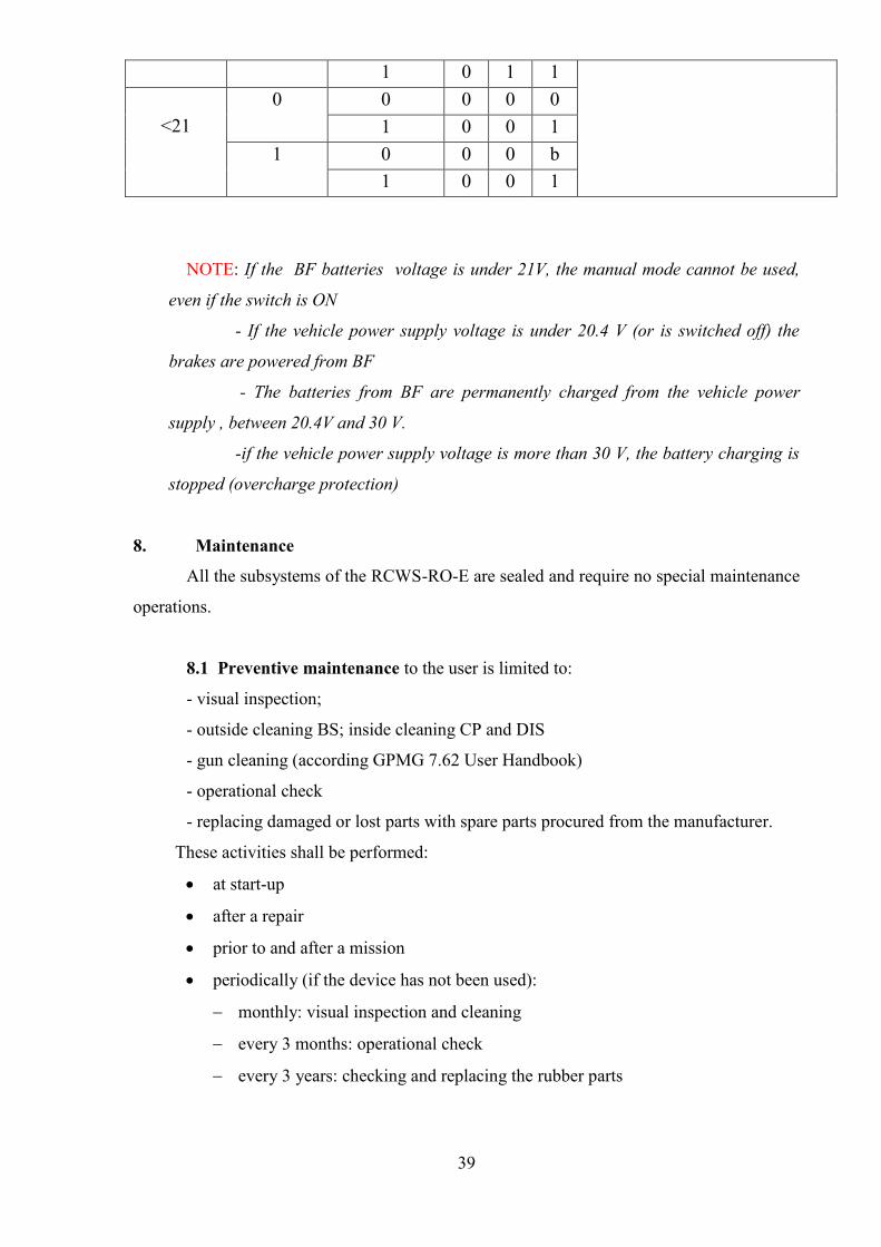
8.1.1 Visual inspection
During visual inspection, make sure the WA subsystems (fig 31) are firmly mounted in
their brackets and check the integrity of the buffers, the cleanness of the exterior surfaces of
BS, the electrical coupling and the gun safe mounting
Fig.31
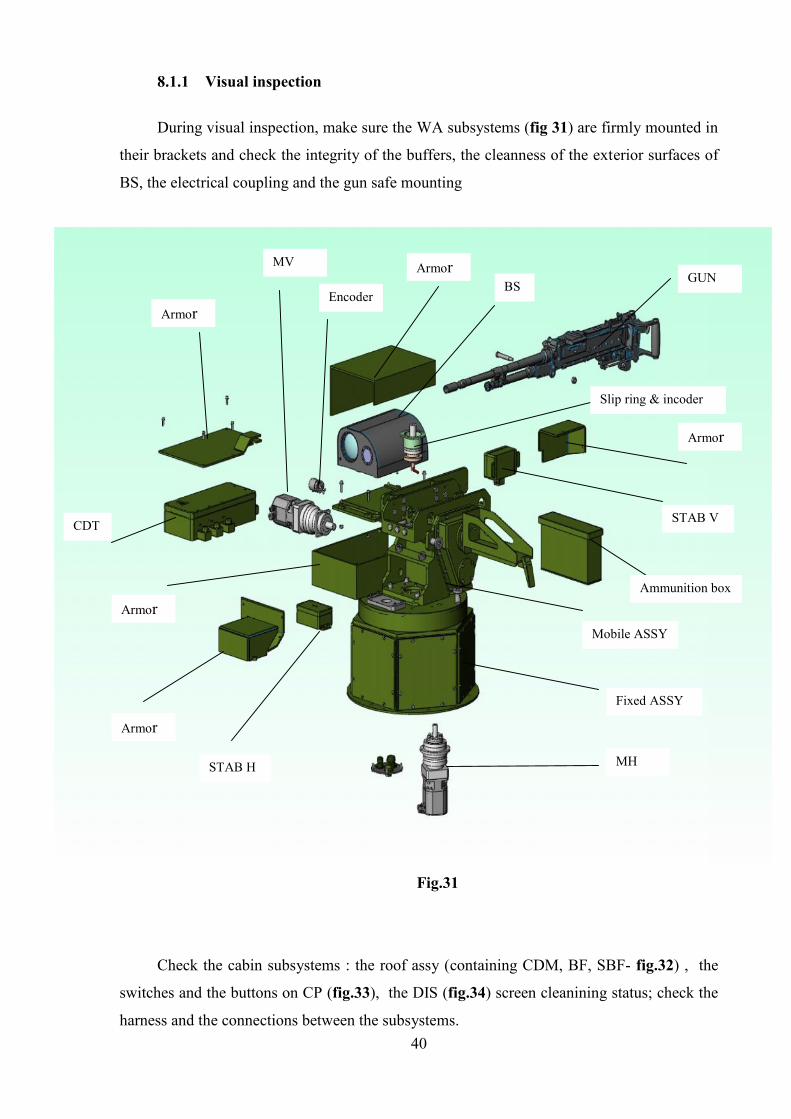
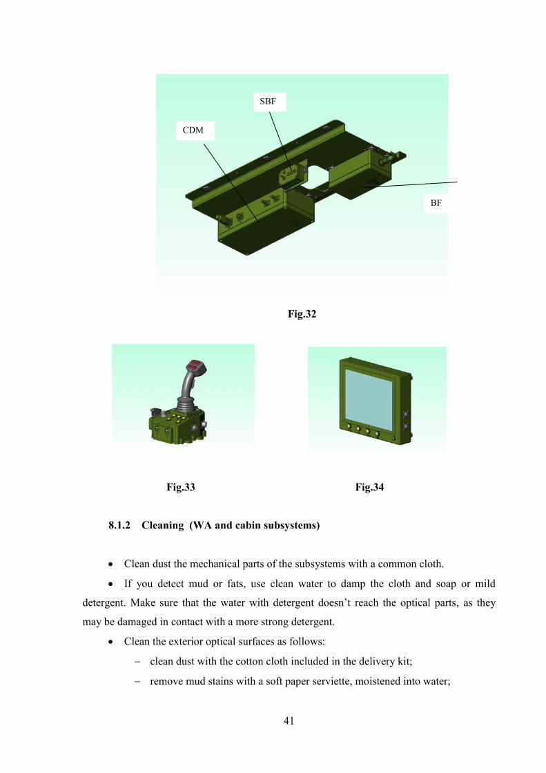
Check the cabin subsystems : the roof assy (containing CDM, BF, SBF- fig.32) , the
switches and the buttons on CP (fig.33), the DIS (fig.34) screen cleanining status; check the
harness and the connections between the subsystems.
Armor
Armor
Armor
Armor
Armor
STAB H
STAB V
GUN
MH
MV
CDT
Fixed ASSY
Mobile ASSY
BS
Slip ring & incoder
Encoder
Ammunition box
41
Fig.32
Fig.33 Fig.34
8.1.2 Cleaning (WA and cabin subsystems)
Clean dust the mechanical parts of the subsystems with a common cloth.
If you detect mud or fats, use clean water to damp the cloth and soap or mild
detergent. Make sure that the water with detergent doesn’t reach the optical parts, as they
may be damaged in contact with a more strong detergent.
Clean the exterior optical surfaces as follows:
clean dust with the cotton cloth included in the delivery kit;
remove mud stains with a soft paper serviette, moistened into water;
BF
CDM
SBF
42
after cleaning, steam the optical surfaces (by blowing) and wipe them gently
with a dry clean cloth;
WARNING!
It is forbidden to use gasoline or organic solvents when cleaning the subsystems.
NOTE The weapon has to be cleaned according to specific instructions (procedures)
from 7.62 GPMG User Handbook
8.1.3 Operational check
- During the operational check, the electrical and software operating procedures are
verified
- The operational check is made according to the chapter 7.3.1
8.2 Corrective maintenance
8.2.1 Failures
If a failure occur, the user has to take the appropriate measures:
- Study the “Troubleshooting” (chapter 9) and see if the failure can be solved
according the manual indications
- replace the foulty item with a spare part, if the failure was located and if the spare
part is available in user warehouse (see chapter 10)
- claim for the spare part if it was not ordered, and replace it when available
- if the failure was not located, connect the special tool ETA to the X1 input of the
CP and move the Rotary switch on the ERRORS position
- send the report displayed on the screen to the manufacturer and wait for his
decision/action
8.2.2 Adjustments
If the firing accuracy seems to be damaged, some adjustments could be necessary in
order to retrieve the factory parameters
The user has to:
- connect the special tool ETA to the X1 input of the CP and move the Rotary switch on the
appropriate position ( CAL, ALIGN, LIM, REF, ERR, FZONE )
-proceed to adjust the chosen parameter according to chapter 7.3.2 – Auxiliary modes

43
NOTE The special tool ETA si not used during operation and firing. It is used only for
maintenance and adjustments
Usually, the NO FIRE ZONES are factory settings, special located for each
type of vehicle. Changing these zones may be performed only with manufacturer support!
A wrong set up performed by the user may cause huge damages, even human lives loss!
9 Troubleshooting
Symptom Possible causes Corrective actionsWhen the SYSTEM switch of theCP is turned “ON”, the SYSTEMled doesn’t light
- There is no voltage inthe vehicle power system- The power supply cableconnector has not beencoupled correctly to theCPU-The fuse of the CP isburnt out or theSYSTEM signallingLED has failed
-Check for the voltage
-Check the firm coupling ofthe connector to the CPU
-Replace the fuse; if it burnsout again, send the device forcheck or repair immediately-replace the SYSTEM led
LEDs CDM, CDT, BS, STB areblinking red-green
Power supply voltageless than 18 V
Check the vehicle batteriesand charge them
LEDs on CP are not lighting asprogrammed
The LED is failed Check the LEDs with BIT Ifthe start sequence is not OK,change CP
The buttons on CP have no theexpected action
The button is failed
You’ve chosen thewrong mode
There are errors in thesystem
Change CP
Check the chosen mode andgo to the right mode
Check the errors with ETA,in auxiliary ERR mode, andchange the indicated failedsubsystem
The LED on CP corresponding to asubsystem is blinking green
The system is initializing
ETA is coupled inauxiliary mode DRIVEand CDM , CDT areadjusted
Wait for the block to beinitialized (no failure)
Check the current mode-NO failure
The LED on CP corresponding to asubsystem is red
The subsystem is notconnectedThe communicationbetween that subsystemand CP failed
Check the connection
Change successively thesubsystem, then CP and thecables between them
The LED on CP corresponding to asubsystem is blinking red (thesystem might work , but not
This subsystem is failedor another subsystemcontrolled by the first
Check the connectionbetween subsystems; if thefailure still persists, check the
44
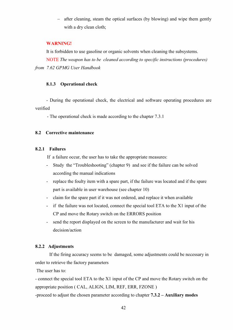
Symptom Possible causes Corrective actionsentirely) one is failed errors using ETA, in auxiliary
mode ERRThe LED on CP corresponding toSTB function is red
STB switch is OFF
The conditions foractivating thestabilisation are notfulfilled
No failure
Check the conditions foractivating the stabilization
The LED on CP corresponding toSTB function is blinking red
A subsystem (at least)working in stabilizationfunction is failed
Check the error messages orcheck the errors using ETA,in auxiliary mode ERR
The LED on CP corresponding toBRK function is red
The switch on SBF isON
Put the switch to OFF (nofailure)
The LED on CP corresponding toBRK function is not lighting whenthe switch is ON
The switch on SBF failedIt is a failure in BFThe cable between BFand SBF , or the cablebetween CP and BFfailed
Change SBFChange BF
Change the cables
The LED on DIS does not light(while the LED SYS on CP lights)
DIS is not connectedLED failed (the imageexists on the screen)Cable between CP andDIS failedDIS failedCP failed
Check DIS connectionCheck the BIT sequence andchange DIS
Change the cableChange DISChange CP
The LED on DIS is blinking green DIS is initializing Wait for finishing theinitialisation
The LED on DIS is red The communicationbetween CP and DISfailed
Change successively DIS, CPand the cable between them
The LED on DIS is blinking red DIS failed Change DISCheck the errors in auxiliaryERR mode
There is no image, though the LEDon DIS is green
DIS failed Change DIS
NO VIDEO message displayed BS is not connectedBS failedDIS failedCable video failed
Check BS connectionChange BSChange DISChange the cable
The LEDs on SBF don’t light The power supplyvoltage is too lowThe LED is failed
No failure
Check the BIT ( all LEDsblinking 3 times) and changeSBF
The LEDs on SBF are blinking There is no power supply
BF is not connected
Check the power supply (nofailure)Check BF connection
When the Joystick arm is pushed inany direction, the WA is notrorating in azimuth
The power supply isunder 18 V
-Check the power supply
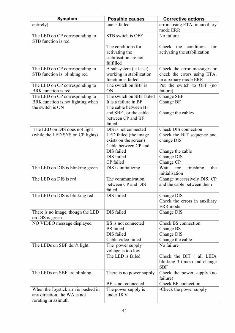
45
Symptom Possible causes Corrective actionsThe conditions forrotating are not fulfilled ( hatch closed, dead manswitch pushed)
There is a failure inCDM or MH
Check the conditions to rotate
Check the error messages orcheck the errors using ETA,in auxiliary mode ERR andchange the failed subsystem
When the Joystick arm is pushed inany direction, the WA is notrorating in elevation
The power supply isunder 18 V
The conditions forrotating are not fulfilled ( hatch closed, dead manswitch pushed)
There is a failure in CDTor MV
-Check the power supply
Check the conditions to rotate
Check the error messages orcheck the errors using ETA,in auxiliary mode ERR andchange the failed subsystem
The overlay grafics for the selectedmode are not displayed
BS failedBS not connectedproperly in the system
Change BSCheck the BS connection
The stabilization is not workingwhen the switch STB on CP is putto ON
A subsystem (at least)working in stabilizationfunction is failed ( theSTB LED on CP isblinking red
Check the error messages orcheck the errors using ETA,in auxiliary mode ERR
The FIRE switch on CP is notworking
The conditions for firingare not fulfilled
The switch is failed
Check the conditions forfiring: the message XX FIREREADY has to be displayedon the bottom of the screen(XX= SS, SB,LB)Change CP
46
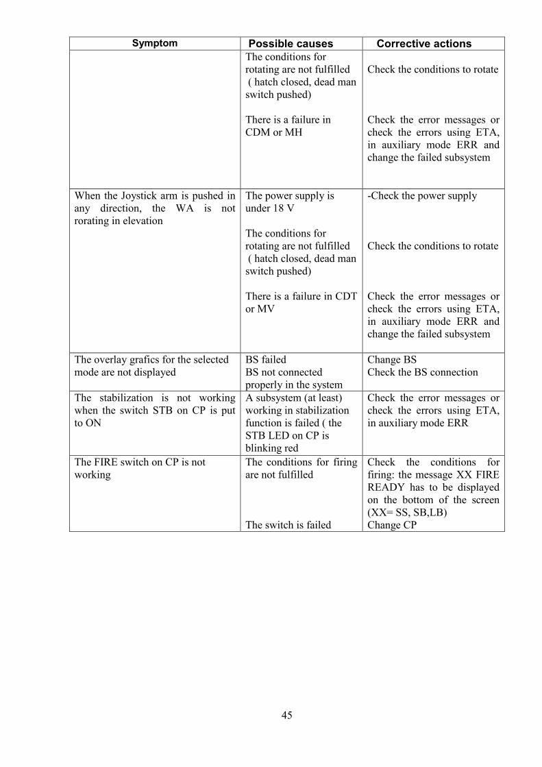
10. Spare parts
Nr. ITEM PICTURE P/N PRODUCED BY NOTES
1.
Sensor blockBS
A.726.02.006.0. S.C. PROOPTICA S.A.
2.
Display 10.4”DIS
A.726.02.008.0. S.C. PROOPTICA S.A.
3
Control PanelCP
A.726.02.007.0. S.C. PROOPTICA S.A.
4
Control box forazimuthCDM
A.726.02.010.0. S.C. PROOPTICA S.A.
5
Control box forelevationCDT
A.726.02.011.0. S.C. PROOPTICA S.A.
6
Horizontal motorMH
A.726.02.002.0. S.C. PROOPTICA S.A.
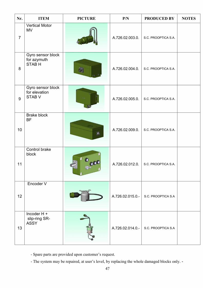
47
Nr. ITEM PICTURE P/N PRODUCED BY NOTES
7
Vertical MotorMV
A.726.02.003.0. S.C. PROOPTICA S.A.
8
Gyro sensor blockfor azymuthSTAB H
A.726.02.004.0. S.C. PROOPTICA S.A.
9
Gyro sensor blockfor elevationSTAB V A.726.02.005.0. S.C. PROOPTICA S.A.
10
Brake blockBF
A.726.02.009.0. S.C. PROOPTICA S.A.
11
Control brakeblock
A.726.02.012.0. S.C. PROOPTICA S.A.
12
Encoder V
A.726.02.015.0.- S.C. PROOPTICA S.A
13
Incoder H + slip-ring SR-ASSY
A.726.02.014.0.- S.C. PROOPTICA S.A
- Spare parts are provided upon customer’s request.
- The system may be repaired, at user’s level, by replacing the whole damaged blocks only. -
48
- The exploded drawings of the RCWS-RO-E and of the subsystems (spare parts) are
presented in Annex 3
11. Storage and transportation conditions
11.1. Storage
Packed products may be stored, before mounting on the vehicles, in storage areas
which are unheated, with natural aeration, made of stone, concrete, wood and thermally
insulated.
Storage temperature: -40° to + 60° C
The products shall be placed on shelves or on the ground, not closer than 1 m to
heating sources and away from direct and long exposure to sun rays.
It is not allowed to store the products in the same room as inflammable liquids, charged
batteries or containers with corrosive chemical substances, petroleum or radioactive products.
Products can be packed for storage as below:
Wipe them of dust and moisture and wrap them in textile or nylon covers, place them
in a transport box (crate), separating the four main subsystems with corrugated board
11.2. Transport
Packed products can be transported by any means of transport (by road, sea or air).
For sea transportation, the systems have to be covered with a protection wax, which
may be removed by hot water
The transport packing must ensure the integrity of the product for the type of transport
and climate conditions agreed by the contract.
12. Warranty
Unless otherwise stipulated in the contract, the manufacturer provides a warranty period
of 12 months, provided that the operation requirements and the safety rules in this operator’s
manual are followed. The warranty period starts on the date of delivery of this product to the
customer