Embed Size (px)
Citation preview
5 5 - B - 0 6
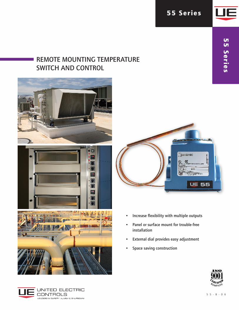
REMOTE MOUNTING TEMPERATURESWITCH AND CONTROL
12 Series55 Series5
5 S
erie
s
• Increase flexibility with multiple outputs
• Panel or surface mount for trouble-free installation
• External dial provides easy adjustment
• Space saving construction
2 u n i t e d e l e c t r i c c o n t r o l s 5 5 - B - 0 6
55 Series
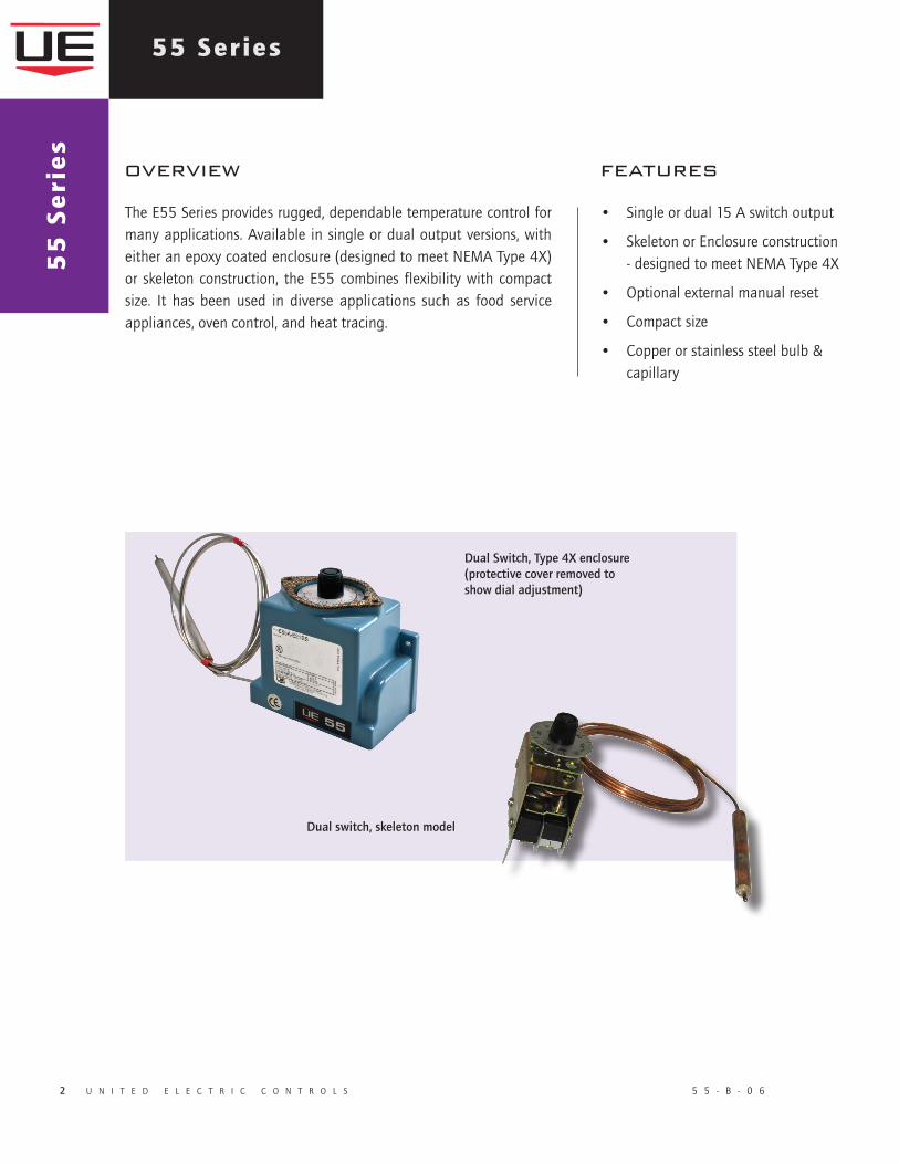
The E55 Series provides rugged, dependable temperature control for many applications. Available in single or dual output versions, with either an epoxy coated enclosure (designed to meet NEMA Type 4X) or skeleton construction, the E55 combines flexibility with compact size. It has been used in diverse applications such as food service appliances, oven control, and heat tracing.
overview features
• Single or dual 15 A switch output
• Skeleton or Enclosure construction - designed to meet NEMA Type 4X
• Optional external manual reset
• Compact size
• Copper or stainless steel bulb & capillary
55
Se
rie
s
Dual Switch, Type 4X enclosure (protective cover removed to show dial adjustment)
Dual switch, skeleton model
5 5 S e r i e s
5 5 - B - 0 6 u n i t e d e l e c t r i c c o n t r o l s 3
specifications
AMBIENT TEMPERATURE -40 to 160°F (-40 to 71°C); set point typically shifts less than 1% of range for a 50°F LIMITS (28°C) ambient temperature change
SET POINT REPEATABILITY ± 1% of adjustable range
SHOCK Set point repeats after 15 G, 10 millisecond duration
VIBRATION Set point repeats after 2.5 G, 5-500 Hz
ENCLOSURE CLASSIFICATION Type E55 & E55A: Designed to meet enclosure type 4X requirements Types E55S & E55AS: Skeleton, open frame construction, not applicable
ENCLOSURE Die cast aluminum, epoxy powder coated with stainless steel, gasketed adjustment cover (E55 and E55A)
SWITCH OUTPUT One or two SPDT; dual switch may be separated up to 100% of range; switches may be wired “normally open” or “normally closed”
ELECTRICAL RATING* 15A, 125/250/480 VAC resistive. 22A, 480 VAC for E55-R25HT and E55-L24HT heat trace models. 2A, 24-30 VDC resistive; 1A, 24-30 VDC inductive. 0.5A, 125 VDC resistive. 0.03A, 125 VDC inductive.ELECTRICAL CONNECTION 1/2” NPT (female) (E55 and E55A)WEIGHT Types E55S, E55AS (skeleton): approximately 12 oz.; Types E55, E55A: approximately 1 lb.
BULB AND CAPILLARY Models E20BC - E23BC: 6 feet copper; Models E20BS - E23BS: 6 feet stainless steel Model R25HT: 10 feet stainless steel Model L24HT: stainless steel, Local sensor, no capillary, for ambient sensing
TEMPERATURE FILL Non-toxic oil
TEMPERATURE DEADBAND Typically 1% of range under laboratory conditions (70°F circulating bath at rate of 1/2°F per minute change)
*NOTE: DC ratings are based on experience - Consult UE for further information
approvalsUE declarations and third-party issued Agency certifications are available for download at www.ueonline.com/prod_approval.html.
UNITED STATES AND CANADA
E55(A) S ModelscULus ListedcURus RecognizedUL 873, C22.2 no. 24, file #E10667
EUROPE
Low Voltage Directive (LVD) (2006/95/EC)UEC compliant to LVDProducts rated lower than 50 VAC and 75 VDC are outside of the scope of the LVD
4 u n i t e d e l e c t r i c c o n t r o l s 5 5 - B - 0 6
55 Series5
5 S
eri
es
model chart
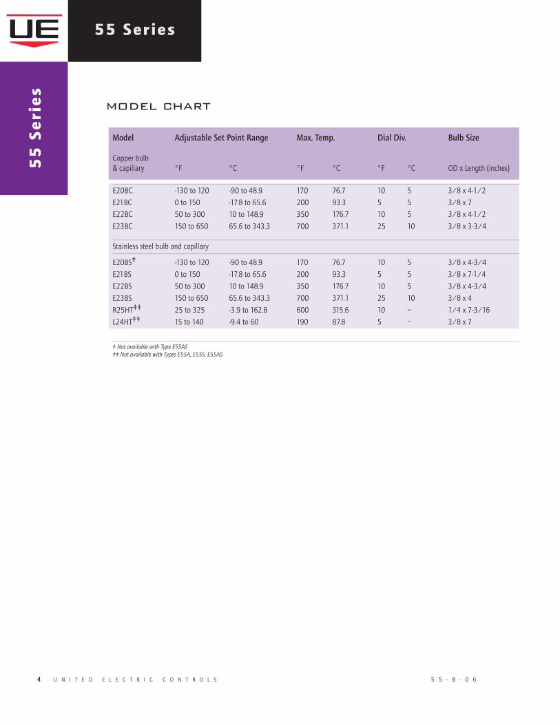
E20BC -130 to 120 -90 to 48.9 170 76.7 10 5 3/8 x 4-1/2
E21BC 0 to 150 -17.8 to 65.6 200 93.3 5 5 3/8 x 7
E22BC 50 to 300 10 to 148.9 350 176.7 10 5 3/8 x 4-1/2
E23BC 150 to 650 65.6 to 343.3 700 371.1 25 10 3/8 x 3-3/4
Stainless steel bulb and capillary
E20BS‡ -130 to 120 -90 to 48.9 170 76.7 10 5 3/8 x 4-3/4
E21BS 0 to 150 -17.8 to 65.6 200 93.3 5 5 3/8 x 7-1/4
E22BS 50 to 300 10 to 148.9 350 176.7 10 5 3/8 x 4-3/4
E23BS 150 to 650 65.6 to 343.3 700 371.1 25 10 3/8 x 4
R25HT‡‡ 25 to 325 -3.9 to 162.8 600 315.6 10 – 1/4 x 7-3/16
L24HT‡‡ 15 to 140 -9.4 to 60 190 87.8 5 – 3/8 x 7
‡ Not available with Type E55AS‡‡ Not available with Types E55A, E55S, E55AS
Model Adjustable Set Point Range Max. Temp. Dial Div. Bulb Size Copper bulb & capillary °F °C °F °C °F °C OD x Length (inches)
5 5 - B - 0 6 u n i t e d e l e c t r i c c o n t r o l s 5
5 5 S e r i e s
how to orderBUILDING A PART NUMBER
Select a Type
Refer to the “Type” section below.
Determine type number based on switch output, enclosure, adjustment and reference.
Select a Model
Refer to the “Model Charts”.
Determine model based on adjustable range, and capillary material.
Select an Option (if applicable)
Refer to the “Options” section. Determine option number based on switch output, optional materials or other product enhancements.
FOR MULTIPLE OPTIONS: Call United Electric Controls.
TYPE E55 Bulb & capillary; one SPDT output; Epoxy coated enclosure; external adjustment with reference dial, tamper-resistant coverE55A Bulb & capillary; two SPDT outputs; Epoxy coated enclosure; external adjustment with reference dial, tamper-resistant cover E55S Bulb & capillary; one SPDT output; skeleton construction; external adjustment with reference dialE55AS Bulb & capillary; two SPDT outputs; skeleton construction; external adjustment with reference dial
SWITCH OPTIONS*0500 Close deadband, 5 A, 125/250 VAC resistive. 3 A, 28 VDC; 1 A, 48 VDC; 0.5 A, 125 VDC resistive. NOT AVAILABLE ON MODELS R25HT, L24HT0140 Gold contacts, 1 A, 125 VAC resistive, NOT AVAILABLE ON MODELS E55-L24HT, E55-R25HT1530 External manual reset, 15 A 125/250/480 VAC resistive; 0.5 A, 125 VDC; 0.25 A, 250 VDC resistive. Reset on increasing temperature. NOT AVAILABLE ON TYPES E55S, E55AS, & MODELS R25HT, L24HT2000 20 A 125/250/480 VAC resistive. 0.5 A, 125 VDC; 0.25 A, 250 VDC resistive. NOT AVAILABLE ON MODELS R25HT, L24HT
GENERALM020 Pilot light. AVAILABLE HEAT TRACE MODELS R25HT, L24HT ONLYM201 Factory set one switch; specify increasing or decreasing temperature and set point. NOT AVAILABLE ON TYPES E55A, E55ASM202 Factory set two switches; specify increasing or decreasing temperature and set point. NOT AVAILABLE ON TYPES E55, E55SM270 Calibrated dial in Celsius. NOT AVAILABLE ON HEAT TRACE MODELS R25HT, L24HT M444 Paper ID tag. NOT AVAILABLE ON HEAT TRACE MODELS R25HT, L24HTM446 Stainless steel ID tag & wire attachment; limited to 2 lines of 25 characters each max.
UNION CONNECTORS**(Not available on model L24HT or R25HT)
Option Replacement Number Description BrassW027 SD6213-27 1/2” NPT w/ 3/4” bushingW045 SD6213-45 3/4” NPTW051 SD6213-51 1/2” NPT
304 Stainless Steel W028 SD6213-28 1/2” NPT w/ 3/4” bushingW046 SD6213-46 3/4” NPT W050 SD6213-50 1/2” NPT
THERMOWELLS** For all bulb & capillary switches, all 1/2” NPT Internal (Not available on models R25HT, L24HT)
Brass W075 SD6225-75 1/2" NPT with 3/4” NPT bushing adapter, 4” BT W191 SD6225-191 1/2” NPT, 4” BTW118 SD6225-118 1/2" NPT with 3/4” NPT bushing adapter, 7” BTW192 SD6225-192 1/2” NPT, 7” BT
316 Stainless SteelW076 SD6225-76 3/4” NPT, 4.5” BT W193 SD6225-193 1/2” NPT, 4.5” BT W119 SD6225-119 3/4" NPT, 7.5” BT W177 SD6225-177 1/2” NPT, 7.5” BT
OPTIONAL LENGTHS:Optional capillary length to 50’ may be available in copper or 304 st/st. Armor or Teflon® capillary protection may be available to lengths less than or equal to capillary length. Consult UE for additional information and availability.
Consult UE regarding repeatability and ambient effects on capillary lengths over 30’. * All switch options have limited DC capabilities. Consult factory for details.** Dimensional drawings for union connectors and thermowells may be found at www.ueonline.com
6 u n i t e d e l e c t r i c c o n t r o l s 5 5 - B - 0 6
55 Series5
5 S
eri
es
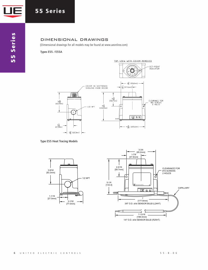
dimensional drawings
Type E55 Heat Tracing Models
Types E55 /E55A
(Dimensional drawings for all models may be found at www.ueonline.com)
5 5 - B - 0 6 u n i t e d e l e c t r i c c o n t r o l s 7
5 5 S e r i e s
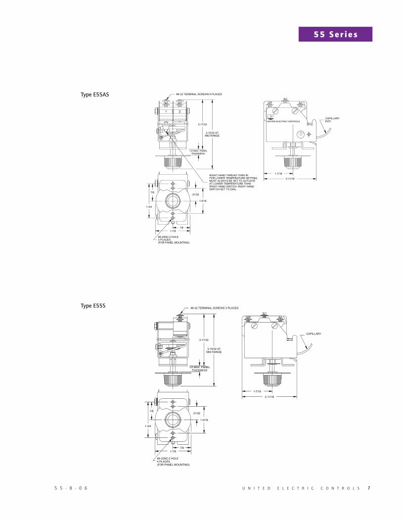
Type E55AS
Type E55S
RECOMMENDED PRACTICES AND WARNINGS
United Electric Controls Company recommends careful consideration of the following factors when specifying and installing UE pressure and temperature units. Before installing a unit, the Installation and Maintenance instructions provided with unit must be read and understood.
• To avoid damaging unit, proof pressure and maximum temperature limits stated in literature and on nameplates must never be exceeded, even by surges in the system. Operation of the unit up to maximum pressure or temperature is acceptable on a limited basis (e.g., start-up, testing) but continuous operation must be restricted to the designated adjustable range. Excessive cycling at maximum pressure or temperature limits could reduce sensor life.
• A back-up unit is necessary for applications where damage to a primary unit could endanger life, limb or property. A high or low limit switch is necessary for applications where a dangerous runaway condition could result.
• The adjustable range must be selected so that incorrect, inadvertent or malicious setting at any range point cannot result in an unsafe system condition.
• Install unit where shock, vibration and ambient temperature fluctuations will not damage unit or affect operation. When applicable, orient unit so that moisture does not enter the enclosure via the electrical connection. When appropriate, this entry point should be sealed to prevent moisture entry.
• Unit must not be altered or modified after shipment. Consult UE if modification is necessary.
• Monitor operation to observe warning signs of possible damage to unit, such as drift in set point or faulty display. Check unit immediately.
• Preventative maintenance and periodic testing is necessary for critical applications where damage could endanger property or personnel.
• Electrical ratings stated in literature and on nameplate must not be exceeded. Overload on a switch can cause damage, even on the first cycle. Wire unit according to local and national electrical codes, using wire size recommended in installation sheet.
• Do not mount unit in ambient temp. exceeding published limits.
LIMITED WARRANTYSeller warrants that the product hereby purchased is, upon delivery, free from defects in material and workmanship and that any such product which is found to be defective in such workmanship or material will be repaired or replaced by Seller (Ex-works, Factory, Watertown, Massachusetts. INCOTERMS); provided, however, that this warranty applies only to equipment found to be so defective within a period of 24 months from the date of manufacture by the Seller. Seller shall not be obligated under this warranty for alleged defects which examination discloses are due to tampering, misuse, neglect, improper storage, and in any case where products are disassembled by anyone other than authorized Seller’s representatives. EXCEPT FOR THE LIMITED WARRANTY OF REPAIR AND REPLACEMENT STATED ABOVE, SELLER DISCLAIMS ALL WARRANTIES WHATSOEVER WITH RESPECT TO THE PRODUCT, INCLUDING ALL IMPLIED WARRANTIES OF MERCHANTABILITY OR FITNESS FOR ANY PARTICULAR PURPOSE.
LIMITATION OF SELLER’S LIABILITYSELLER’S LIABILITY TO BUYER FOR ANY LOSS OR CLAIM, INCLUDING LIABILITY INCURRED IN CONNECTION WITH (I) BREACH OF ANY WARRANTY WHATSOEVER, EXPRESSED OR IMPLIED, (II) A BREACH OF CONTRACT, (III) A NEGLIGENT ACT OR ACTS (OR NEGLIGENT FAILURE TO ACT) COMMITTED BY SELLER, OR (IV) AN ACT FOR WHICH STRICT LIABILITY WILL BE INPUTTED TO SELLER, IS LIMITED TO THE “LIMITED WARRANTY” OF REPAIR AND/OR REPLACEMENT AS SO STATED IN OUR WARRANTY OF PRODUCT. IN NO EVENT SHALL THE SELLER BE LIABLE FOR ANY SPECIAL, INDIRECT, CONSEQUENTIAL OR OTHER DAMAGES OF A LIKE GENERAL NATURE, INCLUDING, WITHOUT LIMITATION, LOSS OF PROFITS OR PRODUCTION, OR LOSS OR EXPENSES OF ANY NATURE INCURRED BY
CP04131000Be sure to visit www.ueonline.com for the latest information.
180 Dexter AvenueWatertown, MA 02472 USATelephone: 617 926-1000 Fax: 617 926-2568www.ueonline.com
FOR A LIST OF OUR INTERNATIONAL AND DOMESTIC REGIONAL SALES OFFICES PLEASE VISIT OUR
WEBPAGE WWW.UEONLINE.COM