Embed Size (px)
Citation preview
Remote PC Guide for VMware Implementation Using ESXi versions 4.01 and 4.1 U2 with vCenter
Document Version: 2012-06-29
This guide is a primer for adding remotely accessible PC or servers into your NETLAB+ equipment pods using the VMware ESXi and vCenter virtualization products.
This guide covers features available in NETLAB+ version 2011.R2 and later. The details of this guide are specific to VMware ESXi versions 4.01 and 4.1 U2 with vCenter. Documentation for interfacing with other versions of VMware virtualization products
can be found in their respective Remote PC Guide for VMware Implementation guides.
Copyright © Network Development Group, Inc. www.netdevgroup.com NETLAB Academy Edition, NETLAB Professional Edition, and NETLAB+ are registered trademarks of Network Development Group, Inc. VMware is a registered trademark of VMware, Inc. Cisco, IOS, Cisco IOS, Networking Academy, CCNA, and CNP are registered trademarks of Cisco Systems, Inc.
Remote PC Guide for VMware Implementation Using ESXi versions 4.01 and 4.1 U2 with vCenter www.netdevgroup.com
6/29/2012 Page 2 of 224
1 Background .......................................................................................................................6
1.1 What should I know before proceeding? ................................................................6
1.2 What is a Remote PC? ...............................................................................................7
1.3 What can users do with a remote PC?.....................................................................8
1.4 What is a Virtual Machine? ................................................................................... 10
1.5 How do NETLAB+, VMware vCenter and VMware ESXi work together? ........... 11
2 Planning ......................................................................................................................... 14
2.1 VMware Product Comparison ............................................................................... 14
2.2 NETLAB+ Feature Support ..................................................................................... 16
2.3 Virtual Machine Software Licenses ....................................................................... 16
2.4 Obtaining VMware vSphere Software and Licenses for the NETLAB+ Infrastructure ..................................................................................................................... 17
2.5 VMware ESXi ........................................................................................................... 17
2.5.1 VMware ESXi Host Requirements ................................................................. 18
2.5.2 Special ESXi Host Requirements for VMware IT Academy .......................... 20
2.5.3 Obtaining VMware ESXi and Licenses ........................................................... 20
2.6 VMware vCenter .................................................................................................... 23
2.6.1 VMware vCenter Server Requirements ........................................................ 23
2.6.2 Obtaining VMware vCenter Server and Licenses ......................................... 25
2.7 Networking Models ................................................................................................ 30
2.7.1 Single-Homed Networking ............................................................................. 31
2.7.1.1 Single-Homed Setup Tasks 32
2.7.2 Dual-Homed Networking ............................................................................... 33
2.7.2.1 Dual-Homed Setup Tasks 34
2.7.3 Secure+ Networking ....................................................................................... 35
2.7.3.1 Secure+ Networking Setup Tasks 36
2.8 Storage Area Networks .......................................................................................... 37
3 VMware ESXi Server Setup ........................................................................................... 38
3.1 Preparing the ESXi Server ...................................................................................... 39
3.1.1 DELL R710 BIOS System changes ................................................................... 39
3.2 DELL R710 RAID Configuration .............................................................................. 43
3.2.1 3x2TB HDD Configuration .............................................................................. 44
3.2.2 3x1TB HDD Configuration .............................................................................. 46
3.3 Installing ESXi on Host Server ................................................................................ 48
3.4 Configure Root Password ...................................................................................... 49
3.5 Network Configuration .......................................................................................... 50
4 VMware vCenter Server Setup ..................................................................................... 56
4.1 vCenter Configuration Options ............................................................................. 56
4.1.1 vCenter Configuration Option 1 .................................................................... 57
4.1.2 vCenter Configuration Option 2 .................................................................... 58
4.1.3 vCenter Configuration Option 3 .................................................................... 59
4.1.4 vCenter Configuration Option 4 .................................................................... 60
4.2 Networking Overview for vCenter Server ............................................................ 61
4.2.1 Virtualized vCenter Server Networking Options .......................................... 61
4.2.1.1 Virtualized vCenter Server with Single Homed Networking 61
Remote PC Guide for VMware Implementation Using ESXi versions 4.01 and 4.1 U2 with vCenter www.netdevgroup.com
6/29/2012 Page 3 of 224
4.2.1.2 Virtualized vCenter Server with Dual Homed Networking 62
4.2.1.3 Virtualized vCenter with Secure+ Networking 63
4.2.2 Bare Metal vCenter Server Networking Options .......................................... 65
4.2.2.1 Bare Metal vCenter Server with Single Homed Networking 65
4.2.2.2 Bare Metal vCenter Server with Dual Homed Networking 66
4.2.2.3 Bare Metal vCenter Server with Secure+ Networking 67
4.3 Configure Management Server ............................................................................. 68
4.4 Install Windows Server 2008 R2 64-bit ................................................................. 68
4.5 Configuring TCP/IP on vCenter Server Network Adapters .................................. 69
4.5.1 Outside Interface ............................................................................................ 69
4.5.2 Inside Interface ............................................................................................... 71
4.6 Installing VMware vCenter and Related Software ............................................... 73
4.6.1 Installing vCenter with Microsoft SQL Server 2008 R2 (Option 1 and 3) .... 73
4.6.1.1 Configure Hostname and Create User Account 74
4.6.1.2 Install Microsoft SQL Server 2008 R2 78
4.6.1.3 Create vCenter Database and ODBC drivers 83
4.6.1.4 Install vCenter with SQL Server 2008 R2 database 88
4.6.2 Installing vCenter with Microsoft SQL Express (Option 2 and 4) ................ 90
4.7 Install the vSphere Client on the vCenter Server System .................................... 91
4.8 Install vCenter Converter ....................................................................................... 92
4.8.1 Install and Enable the vCenter Converter Plug-in ........................................ 93
4.9 Creating a Virtual Datacenter in vCenter ............................................................. 94
4.10 Create Windows User Account and vCenter Role for NETLAB+...................... 97
4.11 Registering a Virtual Datacenter in NETLAB+ ................................................. 105
4.12 Setting the Database Retention Policy ........................................................... 106
5 Adding ESXi Hosts to vCenter and NETLAB+ ............................................................. 108
5.1 Adding ESXi hosts to vCenter .............................................................................. 108
5.2 ESXi Host Virtual Switches ................................................................................... 110
5.3 Verifying vSwitch0 Configuration ........................................................................ 111
5.4 Inside Network Configuration ............................................................................. 112
5.4.1 Creating vSwitch1 and Binding to Physical NIC .......................................... 115
5.4.2 Configuring Control Switch 802.1q Trunk Ports ......................................... 120
5.4.3 Connecting Virtual Machines to Real Equipment Pods ............................. 122
5.4.3.1 Creating a Real Equipment Pod 123
5.4.3.2 Determining the Base VLAN and VLAN Pool 123
5.4.3.3 Creating Port Groups for Pod VLANs on the Inside Network 123
5.4.3.4 Increasing the Inside vSwitch Port Count 124
5.5 Creating a Safe Staging Network ......................................................................... 127
5.6 Adding ESXi hosts in NETLAB+ ............................................................................. 130
5.7 Proactive Resource Awareness ........................................................................... 132
6 vCenter Update Manager ........................................................................................... 134
6.1 Installing vCenter Update Manager with Microsoft SQL Server 2008 R2 (Options 1 and 3) ............................................................................................................................ 135
6.2 Installing vCenter Update Manager with Microsoft SQL Server Express (Options 2 and 4) ............................................................................................................................ 143
Remote PC Guide for VMware Implementation Using ESXi versions 4.01 and 4.1 U2 with vCenter www.netdevgroup.com
6/29/2012 Page 4 of 224
6.3 Install the vCenter Update Manager plug-in ...................................................... 144
6.4 Performing updates using the vCenter Update Manager plug-in .................... 146
7 Building Virtual Machines ........................................................................................... 151
7.1 Using NDG Template Virtual Machines and 3rd Party Virtual Appliances ....... 153
7.2 Creating Virtual Machines from Scratch ............................................................. 155
7.2.1 Providing a Name for Your Virtual Machine ............................................... 156
7.2.2 Selecting a Datastore.................................................................................... 156
7.2.3 Select the Virtual Machine Hardware Version ........................................... 157
7.2.4 Selecting the Guest Operating System ........................................................ 157
7.2.5 Selecting the Number of Processors ........................................................... 158
7.2.6 Configuring the Memory Size ...................................................................... 159
7.2.7 Choosing Network Connections .................................................................. 160
7.2.8 Selecting the Disk Controller........................................................................ 162
7.2.9 Creating a Virtual Hard Disk ......................................................................... 163
7.2.10 Specifying Advanced Options ...................................................................... 164
7.2.11 Verifying the Settings ................................................................................... 165
7.3 Installing a Guest Operating System ................................................................... 166
7.4 Editing the Virtual CD/DVD Device ..................................................................... 166
7.5 Essential Virtual Machine Performance Optimizations ..................................... 168
7.5.1 Installing VMware Tools ............................................................................... 168
7.5.2 Disabling the Desktop Background.............................................................. 170
7.5.3 Setting the Virtual Machine Display Properties ......................................... 171
7.5.4 Adjusting Visual Effects ................................................................................ 172
7.6 Adding Software Applications ............................................................................. 173
7.7 Virtual Machine Snapshots .................................................................................. 173
7.7.1 How NETLAB+ Uses Snapshots .................................................................... 173
7.7.2 Snapshot Best Practices ............................................................................... 174
7.7.3 Taking a New Snapshot ................................................................................ 175
7.7.4 Managing Snapshots .................................................................................... 176
8 NETLAB+ Virtual Machine Inventory.......................................................................... 177
8.1 Virtual Machine Roles .......................................................................................... 177
8.2 How Virtual Machines Become Part of the NETLAB+ Inventory ....................... 178
8.3 Importing VMs into the Virtual Machine Inventory .......................................... 179
8.4 Virtual Machine Cloning ...................................................................................... 181
8.4.1 Golden Masters and Golden Snapshots ...................................................... 182
8.4.2 Using NETLAB+ to Clone a Single Virtual Machine ..................................... 182
8.5 Assigning Virtual Machines to Pods .................................................................... 186
9 Cloning Virtual Machine Pods .................................................................................... 193
9.1 Golden Masters and Golden Snapshots ............................................................. 195
9.2 Creating a Master Pod ......................................................................................... 195
9.3 Cloning a Virtual Machine Pod Using Linked Clones.......................................... 196
9.4 Tasks to Perform After Pod Cloning .................................................................... 199
9.5 Saving Time on Subsequent Pod Cloning........................................................... 199
9.6 Creating a Full Clone of a Virtual Machine Equipment Pod .............................. 200
9.7 Creating Pods that Run on a Multiple VMware ESXi Hosts ............................... 200
Remote PC Guide for VMware Implementation Using ESXi versions 4.01 and 4.1 U2 with vCenter www.netdevgroup.com
6/29/2012 Page 5 of 224
10 Virtual Machine Operations ....................................................................................... 203
10.1 Delete All Virtual Machines in a Pod ............................................................... 204
10.2 Deleting Individual Virtual Machines .............................................................. 205
10.3 Changing the Name of a Virtual Machine ....................................................... 207
10.4 Changing the Role of a Virtual Machine ......................................................... 208
10.5 Migrating a Virtual Machine to a Different ESXi Host ................................... 209
11 Using NDG Automated Pods ...................................................................................... 211
11.1 NDG Virtual Machine Topologies .................................................................... 211
11.2 NDG Real Equipment Topologies .................................................................... 212
11.3 Setting the Local System ID When Using Multiple NETLAB+ Systems .......... 213
Appendix A Manual Network Setup and Troubleshooting ........................................ 214
Appendix A.1 Creating Inside VLANs that Connect to Real Equipment .................... 214
Appendix A.1.1 Creating a Real Equipment Pod .................................................... 215
Appendix A.1.2 Determining the Base VLAN and VLAN Pool ................................ 216
Appendix A.1.3 Creating Port Groups for Pod VLANs on the Inside Network ..... 218
Appendix A.2 Verifying Connectivity Between Virtual Machines and Lab Gear ...... 221
Remote PC Guide for VMware Implementation Using ESXi versions 4.01 and 4.1 U2 with vCenter www.netdevgroup.com
6/29/2012 Page 6 of 224
1 Background NETLAB+ remote PCs and servers in a pod can be implemented using virtual machines running on VMware vSphere 4. The flexibility and broad selection of operating systems and configurations that may be provisioned on a virtual machine offer great potential to support IT training in a wide range of disciplines using NETLAB+. This guide provides information on NETLAB+ remote PC VMware implementation, using ESXi versions 4.01 and 4.1 U2 with vCenter. In the subsections below, we will begin by bringing to your attention the prerequisite knowledge recommended, along with building a fundamental understanding of how remote PCs, virtualization and NETLAB+ work together.
Objectives
What should I know before proceeding?
What is a remote PC?
What can users do with a remote PC?
What is a virtual machine?
How do NETLAB+, VMware vCenter and VMware ESXi work together?
1.1 What should I know before proceeding?
NETLAB+ communicates with VMware vSphere to perform automated tasks and virtual machine management. Users of this guide should have a working knowledge of VMware vCenter, the vSphere Client and VMware ESXi. NETLAB+ administrators using this guide should be comfortable with the process of creating and configuring a virtual machine “from scratch” (using the vSphere Client). The VMware vSphere Virtual Machine Administration Guide provides detailed guidance on provisioning virtual machines.
Remote PC Guide for VMware Implementation Using ESXi versions 4.01 and 4.1 U2 with vCenter www.netdevgroup.com
6/29/2012 Page 7 of 224
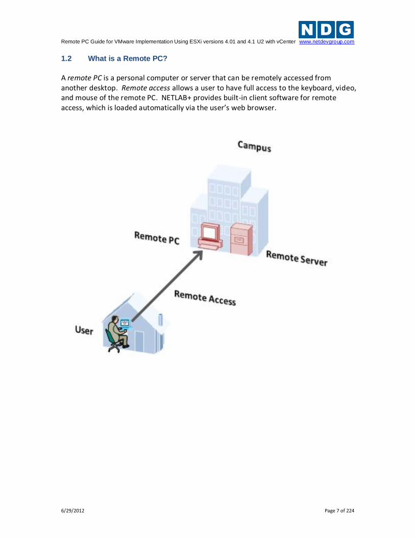
1.2 What is a Remote PC?
A remote PC is a personal computer or server that can be remotely accessed from another desktop. Remote access allows a user to have full access to the keyboard, video, and mouse of the remote PC. NETLAB+ provides built-in client software for remote access, which is loaded automatically via the user’s web browser.
Remote PC Guide for VMware Implementation Using ESXi versions 4.01 and 4.1 U2 with vCenter www.netdevgroup.com
6/29/2012 Page 8 of 224
1.3 What can users do with a remote PC?
Users can remotely access the keyboard, video, and mouse of a remote PC. NETLAB+ also provides special features such as shared simultaneous access, interfacing with real lab equipment (routers, switches, and firewalls), remotely powering a PC on or off, and restoring the PC to a clean state. This offers a wide range of possibilities. Here are a few scenarios that are being used today.
Online Lab Delivery. Provide students with self-paced, scheduled access to real operating systems and application software, without distributing software or licenses.
Distance Learning. Provide remote instructor-led training by allowing simultaneous shared access to remote PCs and remote servers. Several users can connect to and share the remote PC’s graphical user interface at the same time. Using NETLAB+, students can observe what the instructor is doing on the remote PC, and vice-versa.
Resource Scheduling. Provide scheduled usage to limited physical lab equipment and virtual machine host servers. Proactive Resource Awareness allows you to timeshare virtualization servers using the NETLAB+ scheduler.
Online Network Training. Provides online delivery of network training. Remote PCs can be interface with real lab equipment, such as routers, switches, and firewalls, all of which can be accessed remotely using NETLAB+.
Online General IT Training. Provide on-line access to real operating systems and real application software. Using NETLAB+, remote PCs can be completely isolated from production networks, providing a safe environment for instructors and students to do things that are not typically allowed on production networks. Students can safely experience administrative privileges in complex computing environments. You can now provide labs that are not practical for students to set up at home, or scenarios that would be too difficult to set up by new IT students. NETLAB+ includes 25 virtual topologies that can be used to teach a variety of courses, including Linux, Microsoft or Cyber Security. Pods using these topologies can be created very quickly using NETLAB+'s pod cloning and automated network features.
Online Security Training. Provides online delivery of security training. Using NETLAB+, remote PCs can be completely isolated from production networks, providing a safe environment for instructors and students to do things that are not typically allowed on production networks. This might include configuring PCs and lab devices using administrator privileges, installing new software, capturing network traffic, experimenting with firewalls and VPNs, dealing with live viruses
Remote PC Guide for VMware Implementation Using ESXi versions 4.01 and 4.1 U2 with vCenter www.netdevgroup.com
6/29/2012 Page 9 of 224
and malware, and scanning networks. At the end of the lab reservation, NETLAB+ will undo any changes.
VMware vSphere ICM Course. The VMware vSphere ICM course prepares your students for the VMware Certified Professional exam. NDG has partnered with VMware to prepare a series of labs for the NETLAB+ environment. Using the virtualization and pod assignment capabilities of NETLAB+, each student has access to their own set of virtual equipment, which they may maintain exclusive use of throughout the course. Student pods can be created very quickly using NETLAB+'s pod cloning and automated network features. NETLAB+'s use of virtualized lab components results in a significant cost reduction by allowing several pods to run simultaneously on one physical server. For more information, please visit https://www.vmware.com/partners/programs/vap/.
Remote PC Guide for VMware Implementation Using ESXi versions 4.01 and 4.1 U2 with vCenter www.netdevgroup.com
6/29/2012 Page 10 of 224
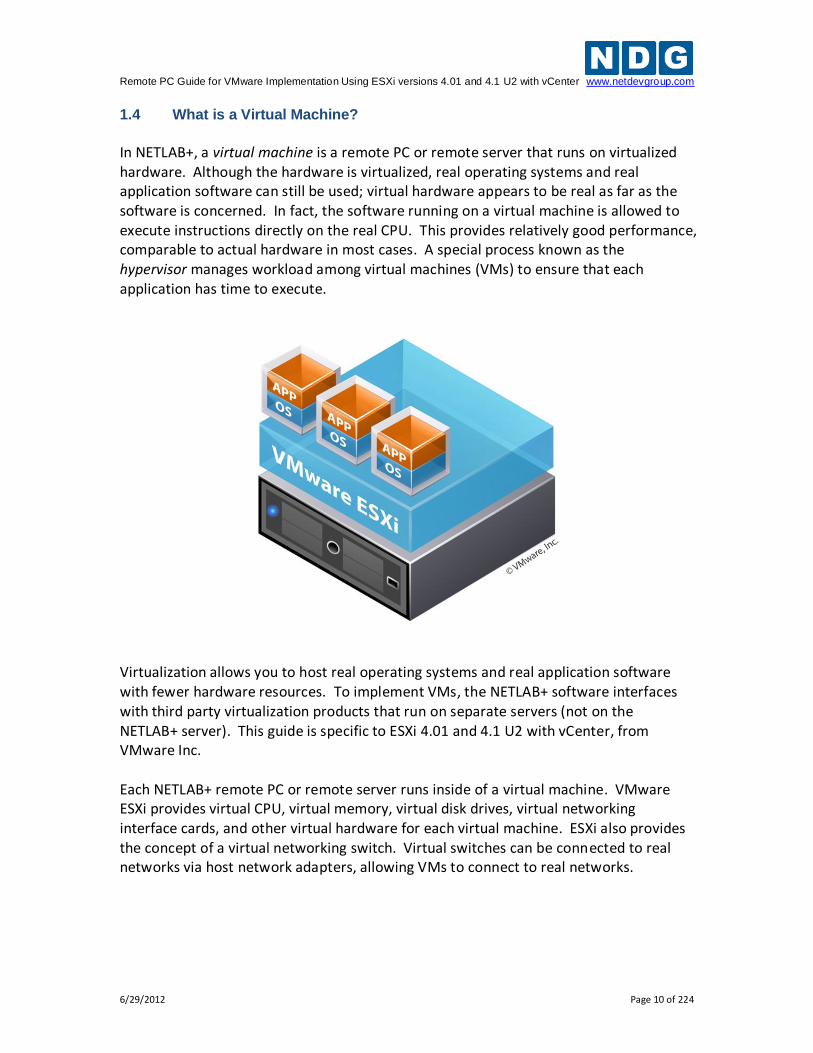
1.4 What is a Virtual Machine?
In NETLAB+, a virtual machine is a remote PC or remote server that runs on virtualized hardware. Although the hardware is virtualized, real operating systems and real application software can still be used; virtual hardware appears to be real as far as the software is concerned. In fact, the software running on a virtual machine is allowed to execute instructions directly on the real CPU. This provides relatively good performance, comparable to actual hardware in most cases. A special process known as the hypervisor manages workload among virtual machines (VMs) to ensure that each application has time to execute.
Virtualization allows you to host real operating systems and real application software with fewer hardware resources. To implement VMs, the NETLAB+ software interfaces with third party virtualization products that run on separate servers (not on the NETLAB+ server). This guide is specific to ESXi 4.01 and 4.1 U2 with vCenter, from VMware Inc. Each NETLAB+ remote PC or remote server runs inside of a virtual machine. VMware ESXi provides virtual CPU, virtual memory, virtual disk drives, virtual networking interface cards, and other virtual hardware for each virtual machine. ESXi also provides the concept of a virtual networking switch. Virtual switches can be connected to real networks via host network adapters, allowing VMs to connect to real networks.
Remote PC Guide for VMware Implementation Using ESXi versions 4.01 and 4.1 U2 with vCenter www.netdevgroup.com
6/29/2012 Page 11 of 224
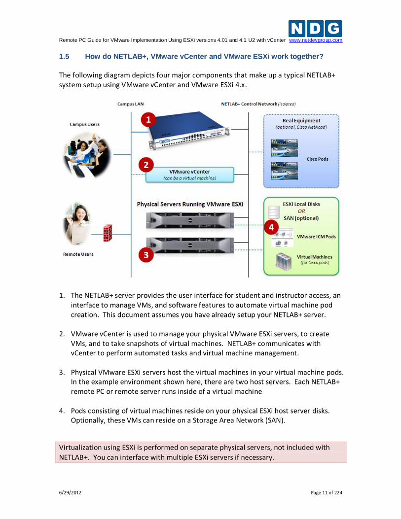
1.5 How do NETLAB+, VMware vCenter and VMware ESXi work together?
The following diagram depicts four major components that make up a typical NETLAB+ system setup using VMware vCenter and VMware ESXi 4.x.
1. The NETLAB+ server provides the user interface for student and instructor access, an
interface to manage VMs, and software features to automate virtual machine pod creation. This document assumes you have already setup your NETLAB+ server.
2. VMware vCenter is used to manage your physical VMware ESXi servers, to create
VMs, and to take snapshots of virtual machines. NETLAB+ communicates with vCenter to perform automated tasks and virtual machine management.
3. Physical VMware ESXi servers host the virtual machines in your virtual machine pods.
In the example environment shown here, there are two host servers. Each NETLAB+ remote PC or remote server runs inside of a virtual machine
4. Pods consisting of virtual machines reside on your physical ESXi host server disks. Optionally, these VMs can reside on a Storage Area Network (SAN).
Virtualization using ESXi is performed on separate physical servers, not included with
NETLAB+. You can interface with multiple ESXi servers if necessary.
Remote PC Guide for VMware Implementation Using ESXi versions 4.01 and 4.1 U2 with vCenter www.netdevgroup.com
6/29/2012 Page 12 of 224
Here is list of features and benefits provided by NETLAB+, working in conjunction with VMware vCenter and VMware ESXi.
Remote Access. The keyboard, video and mouse of each virtual machine can be accessed without a “backdoor” network or interface on the virtual machine. Access to a virtual machine is proxied through NETLAB+ and the virtualization host system, similar to KVM-over-IP hardware solutions. No special client software (other than Java) is required on the user’s computer. NETLAB+ will download its remote PC access application to the client whenever the user clicks on a PC.
Sharing. Multiple users can share access to a virtual machine simultaneously.
Connection Proxy. NETLAB+ multiplexes virtual machine traffic using a single IP address and two TCP ports. It also provides a front-end to the virtual machine environment, so that virtualization servers and VMs do not have to be placed on production networks. This significantly increases security and eases firewall administration. If the user has a valid lab reservation, NETLAB+ will proxy client access to the keyboard, video and mouse of the virtual machine. This access is terminated when the lab reservation completes, ensuring that users of different reservations do not interfere with each other.
Automated Operations. Users may power on, power off, and revert to clean state (scrub) from the NETLAB+ web interface.
Snapshots. NETLAB+ supports revert to snapshot. Changes to a virtual machine can be discarded at the end of a lab reservation, returning the PC to a clean state.
Progressive Labs. Using NETLAB+ Pod Assigner, students may be assigned their own pod and personal VMs for an entire course. These VMs will retain their state between lab reservations.
Linked Virtual Machines. NETLAB+ cloning operations support linked virtual machines. A linked virtual machine shares virtual disks with a master virtual machine in an ongoing manner. This conserves disk space and allows multiple virtual machines to use the same software installation. Linked virtual machines can be created very quickly because most of the disk is shared with the master VM.
Pod Cloning. Pods containing only virtual machines can be cloned in a single operation. This is called pod cloning. The NETLAB+ administrator can clone a master pod very quickly. Using linked virtual machines, a typical pod can be cloned in one minute or less.
Automatic Networking. Many NDG provided pods templates support automatic networking. When a pod starts, NETLAB+ will create all the necessary virtual
Remote PC Guide for VMware Implementation Using ESXi versions 4.01 and 4.1 U2 with vCenter www.netdevgroup.com
6/29/2012 Page 13 of 224
switches and/or port groups on the VM’s host server, and bind each virtual machine network adapter to the correct port group. At the end of the lab reservation, NETLAB+ will delete the virtual switches and port groups used by the pod to free networking resources.
Automatic Remote Display Setup. NETLAB+ now supports automatic setup of remote display parameters on virtual machines. This feature combined with pod cloning and automatic networking allows pods to be deployed very quickly from a set of master VMs without any manual setup.
Proactive Resource Awareness. Proactive Resource Awareness allows you to time-share virtualization servers using the NETLAB+ scheduler. If scheduling a particular pod would exceed the virtualization host server limits in a 30-minute time slot, the pod cannot be scheduled at that time and will be clearly indicated on the scheduler. This feature allows you to increase trainees with fewer servers while providing a good lab experience.
VM Deletion. Virtual machines can be removed from the inventory and/or completely from the disk directly from NETLAB+. When deleting a pod, NETLAB+ provides the option to delete all virtual machines in one operation.
Remote PC Guide for VMware Implementation Using ESXi versions 4.01 and 4.1 U2 with vCenter www.netdevgroup.com
6/29/2012 Page 14 of 224
2 Planning 2.1 VMware Product Comparison
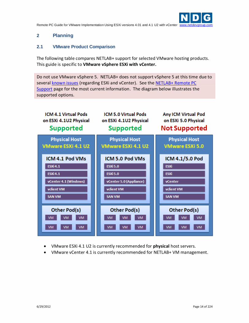
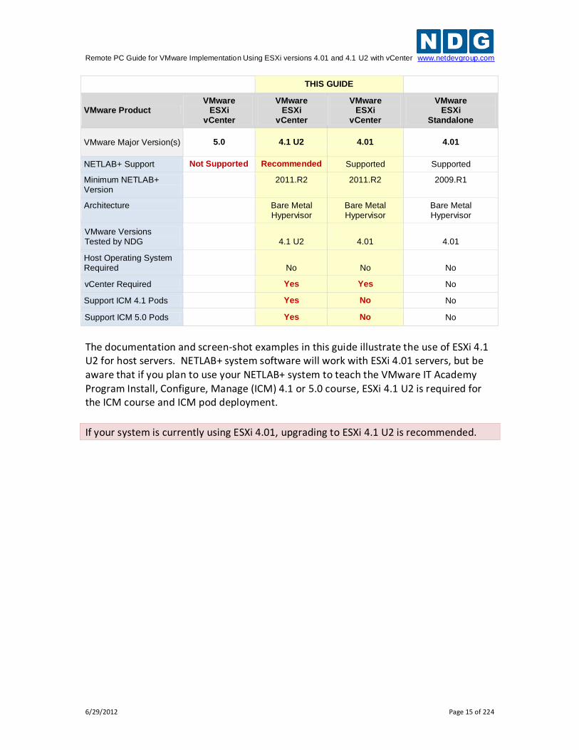
The following table compares NETLAB+ support for selected VMware hosting products. This guide is specific to VMware vSphere ESXi with vCenter.
Do not use VMware vSphere 5. NETLAB+ does not support vSphere 5 at this time due to several known issues (regarding ESXi and vCenter). See the NETLAB+ Remote PC Support page for the most current information. The diagram below illustrates the supported options.
VMware ESXi 4.1 U2 is currently recommended for physical host servers.
VMware vCenter 4.1 is currently recommended for NETLAB+ VM management.
Remote PC Guide for VMware Implementation Using ESXi versions 4.01 and 4.1 U2 with vCenter www.netdevgroup.com
6/29/2012 Page 15 of 224
THIS GUIDE
VMware Product VMware
ESXi vCenter
VMware ESXi
vCenter
VMware ESXi
vCenter
VMware ESXi
Standalone
VMware Major Version(s) 5.0 4.1 U2 4.01 4.01
NETLAB+ Support Not Supported Recommended Supported Supported
Minimum NETLAB+ Version
2011.R2 2011.R2 2009.R1
Architecture
Bare Metal Hypervisor
Bare Metal Hypervisor
Bare Metal Hypervisor
VMware Versions Tested by NDG
4.1 U2
4.01
4.01
Host Operating System Required
No
No
No
vCenter Required Yes Yes No
Support ICM 4.1 Pods Yes No No
Support ICM 5.0 Pods Yes No No
The documentation and screen-shot examples in this guide illustrate the use of ESXi 4.1 U2 for host servers. NETLAB+ system software will work with ESXi 4.01 servers, but be aware that if you plan to use your NETLAB+ system to teach the VMware IT Academy Program Install, Configure, Manage (ICM) 4.1 or 5.0 course, ESXi 4.1 U2 is required for the ICM course and ICM pod deployment.
If your system is currently using ESXi 4.01, upgrading to ESXi 4.1 U2 is recommended.
Remote PC Guide for VMware Implementation Using ESXi versions 4.01 and 4.1 U2 with vCenter www.netdevgroup.com
6/29/2012 Page 16 of 224
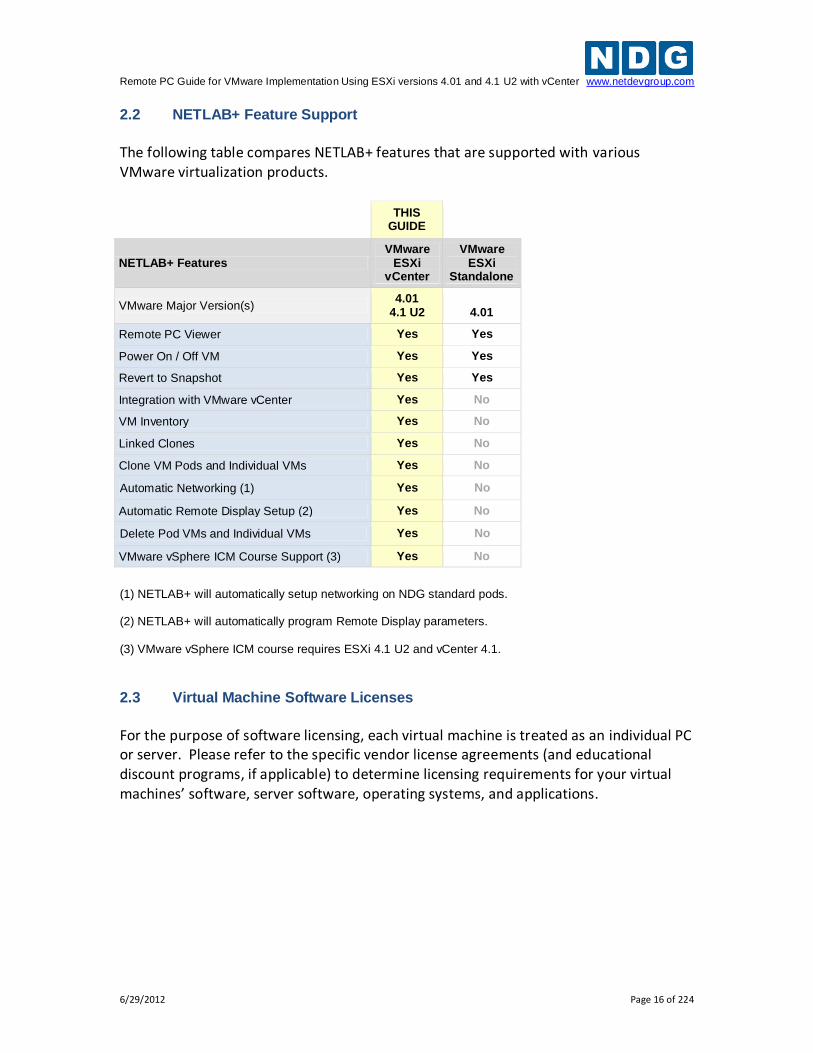
2.2 NETLAB+ Feature Support
The following table compares NETLAB+ features that are supported with various VMware virtualization products.
THIS
GUIDE
NETLAB+ Features VMware
ESXi vCenter
VMware ESXi
Standalone
VMware Major Version(s) 4.01
4.1 U2
4.01
Remote PC Viewer Yes Yes
Power On / Off VM Yes Yes
Revert to Snapshot Yes Yes
Integration with VMware vCenter Yes No
VM Inventory Yes No
Linked Clones Yes No
Clone VM Pods and Individual VMs Yes No
Automatic Networking (1) Yes No
Automatic Remote Display Setup (2) Yes No
Delete Pod VMs and Individual VMs Yes No
VMware vSphere ICM Course Support (3) Yes No
(1) NETLAB+ will automatically setup networking on NDG standard pods. (2) NETLAB+ will automatically program Remote Display parameters. (3) VMware vSphere ICM course requires ESXi 4.1 U2 and vCenter 4.1.
2.3 Virtual Machine Software Licenses
For the purpose of software licensing, each virtual machine is treated as an individual PC or server. Please refer to the specific vendor license agreements (and educational discount programs, if applicable) to determine licensing requirements for your virtual machines’ software, server software, operating systems, and applications.
Remote PC Guide for VMware Implementation Using ESXi versions 4.01 and 4.1 U2 with vCenter www.netdevgroup.com
6/29/2012 Page 17 of 224
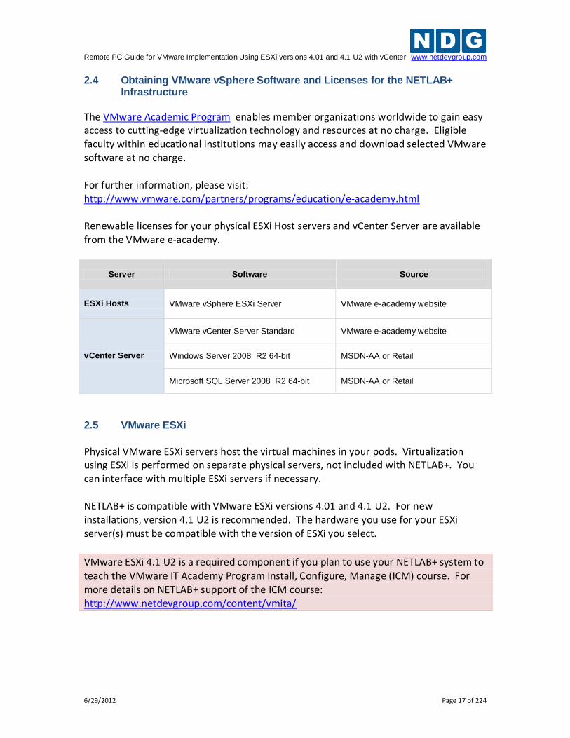
2.4 Obtaining VMware vSphere Software and Licenses for the NETLAB+ Infrastructure
The VMware Academic Program enables member organizations worldwide to gain easy access to cutting-edge virtualization technology and resources at no charge. Eligible faculty within educational institutions may easily access and download selected VMware software at no charge. For further information, please visit: http://www.vmware.com/partners/programs/education/e-academy.html Renewable licenses for your physical ESXi Host servers and vCenter Server are available from the VMware e-academy.
Server Software
Source
ESXi Hosts VMware vSphere ESXi Server VMware e-academy website
vCenter Server
VMware vCenter Server Standard VMware e-academy website
Windows Server 2008 R2 64-bit MSDN-AA or Retail
Microsoft SQL Server 2008 R2 64-bit MSDN-AA or Retail
2.5 VMware ESXi
Physical VMware ESXi servers host the virtual machines in your pods. Virtualization using ESXi is performed on separate physical servers, not included with NETLAB+. You can interface with multiple ESXi servers if necessary. NETLAB+ is compatible with VMware ESXi versions 4.01 and 4.1 U2. For new installations, version 4.1 U2 is recommended. The hardware you use for your ESXi server(s) must be compatible with the version of ESXi you select.
VMware ESXi 4.1 U2 is a required component if you plan to use your NETLAB+ system to teach the VMware IT Academy Program Install, Configure, Manage (ICM) course. For more details on NETLAB+ support of the ICM course: http://www.netdevgroup.com/content/vmita/
Remote PC Guide for VMware Implementation Using ESXi versions 4.01 and 4.1 U2 with vCenter www.netdevgroup.com
6/29/2012 Page 18 of 224
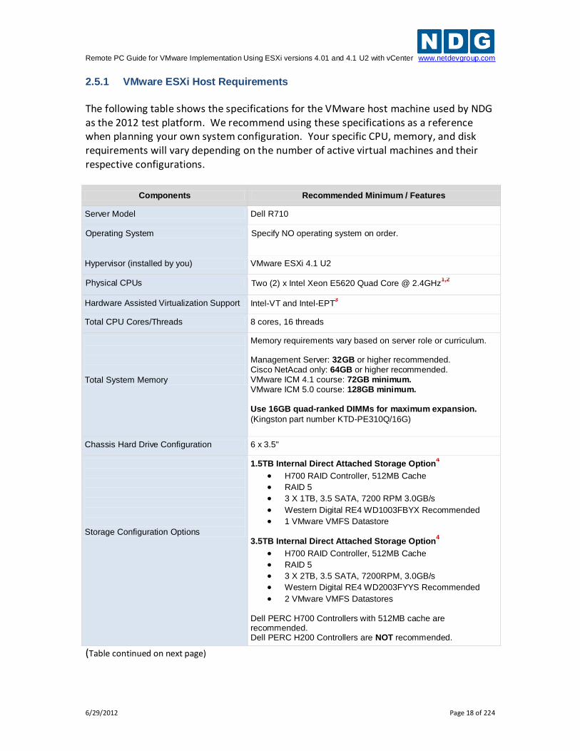
2.5.1 VMware ESXi Host Requirements
The following table shows the specifications for the VMware host machine used by NDG as the 2012 test platform. We recommend using these specifications as a reference when planning your own system configuration. Your specific CPU, memory, and disk requirements will vary depending on the number of active virtual machines and their respective configurations.
Components Recommended Minimum / Features
Server Model Dell R710
Operating System Specify NO operating system on order.
Hypervisor (installed by you) VMware ESXi 4.1 U2
Physical CPUs Two (2) x Intel Xeon E5620 Quad Core @ 2.4GHz1,2
Hardware Assisted Virtualization Support Intel-VT and Intel-EPT3
Total CPU Cores/Threads 8 cores, 16 threads
Total System Memory
Memory requirements vary based on server role or curriculum. Management Server: 32GB or higher recommended. Cisco NetAcad only: 64GB or higher recommended. VMware ICM 4.1 course: 72GB minimum. VMware ICM 5.0 course: 128GB minimum. Use 16GB quad-ranked DIMMs for maximum expansion.
(Kingston part number KTD-PE310Q/16G)
Chassis Hard Drive Configuration 6 x 3.5"
Storage Configuration Options
1.5TB Internal Direct Attached Storage Option4
H700 RAID Controller, 512MB Cache
RAID 5
3 X 1TB, 3.5 SATA, 7200 RPM 3.0GB/s
Western Digital RE4 WD1003FBYX Recommended
1 VMware VMFS Datastore
3.5TB Internal Direct Attached Storage Option4
H700 RAID Controller, 512MB Cache
RAID 5
3 X 2TB, 3.5 SATA, 7200RPM, 3.0GB/s
Western Digital RE4 WD2003FYYS Recommended
2 VMware VMFS Datastores Dell PERC H700 Controllers with 512MB cache are recommended. Dell PERC H200 Controllers are NOT recommended.
(Table continued on next page)
Remote PC Guide for VMware Implementation Using ESXi versions 4.01 and 4.1 U2 with vCenter www.netdevgroup.com
6/29/2012 Page 19 of 224
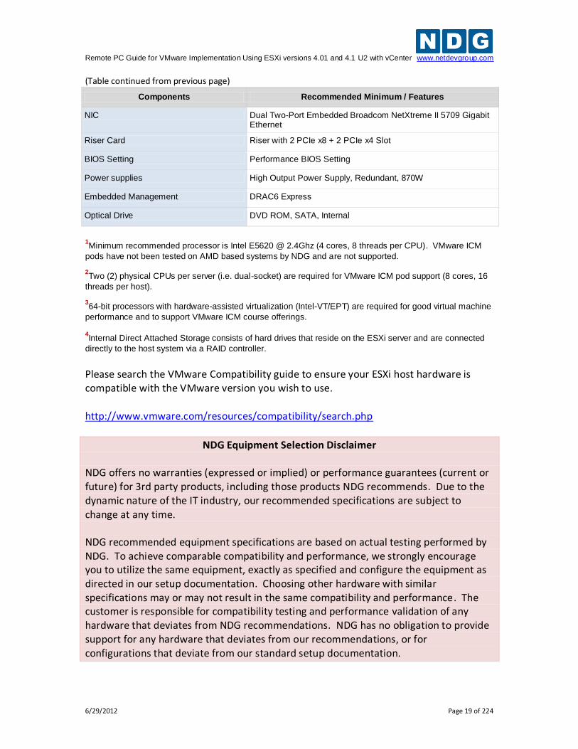
(Table continued from previous page)
Components Recommended Minimum / Features
NIC Dual Two-Port Embedded Broadcom NetXtreme II 5709 Gigabit Ethernet
Riser Card Riser with 2 PCIe x8 + 2 PCIe x4 Slot
BIOS Setting Performance BIOS Setting
Power supplies High Output Power Supply, Redundant, 870W
Embedded Management DRAC6 Express
Optical Drive DVD ROM, SATA, Internal
1Minimum recommended processor is Intel E5620 @ 2.4Ghz (4 cores, 8 threads per CPU). VMware ICM
pods have not been tested on AMD based systems by NDG and are not supported. 2Two (2) physical CPUs per server (i.e. dual-socket) are required for VMware ICM pod support (8 cores, 16
threads per host). 364-bit processors with hardware-assisted virtualization (Intel-VT/EPT) are required for good virtual machine
performance and to support VMware ICM course offerings.
4Internal Direct Attached Storage consists of hard drives that reside on the ESXi server and are connected
directly to the host system via a RAID controller.
Please search the VMware Compatibility guide to ensure your ESXi host hardware is compatible with the VMware version you wish to use.
http://www.vmware.com/resources/compatibility/search.php
NDG Equipment Selection Disclaimer NDG offers no warranties (expressed or implied) or performance guarantees (current or future) for 3rd party products, including those products NDG recommends. Due to the dynamic nature of the IT industry, our recommended specifications are subject to change at any time. NDG recommended equipment specifications are based on actual testing performed by NDG. To achieve comparable compatibility and performance, we strongly encourage you to utilize the same equipment, exactly as specified and configure the equipment as directed in our setup documentation. Choosing other hardware with similar specifications may or may not result in the same compatibility and performance. The customer is responsible for compatibility testing and performance validation of any hardware that deviates from NDG recommendations. NDG has no obligation to provide support for any hardware that deviates from our recommendations, or for configurations that deviate from our standard setup documentation.
Remote PC Guide for VMware Implementation Using ESXi versions 4.01 and 4.1 U2 with vCenter www.netdevgroup.com
6/29/2012 Page 20 of 224
2.5.2 Special ESXi Host Requirements for VMware IT Academy
Hardware Assisted Virtualization (Intel VT-x) is REQUIRED on any host you use for the VMware IT Academy Install, Configure, Manage (ICM) course.
The VMware IT Academy labs have not been tested on AMD processors and are not
supported on AMD processors.
The NETLAB+ VMware ICM Pod Installation and Configuration Guide provides detailed instructions for delivering the ICM course using your NETLAB+ system. You may obtain this guide through the NDG Lab Resource Center for the VMware IT Academy: http://www.netdevgroup.com/content/vmita/resource/ 2.5.3 Obtaining VMware ESXi and Licenses
The following procedure assumes you are a registered member of the VMware Academic Program (VMAP). Non-members can obtain evaluation copies of VMware vCenter and ESXi software from http://www.vmware.com and purchase through retail partners. When downloading ESXi it is important to select a version that is compatible with NETLAB+.
NETLAB+ is compatible with VMware ESXi versions 4.01 and 4.1 U2.
For new installations, version 4.1 U2 is recommended.
VMware ESXi 4.1 U2 is a required component if you plan to use your NETLAB+ system to teach the VMware IT Academy Program Install, Configure, Manage (ICM) course.
Keep in mind that VMware ESXi version 5.0 is not supported. Do not select VMware
ESXi 5.0.
The current link from VMware Academic Alliance Program is for VMware ESXi 4.1. You
will need to upgrade to 4.1 U2 as recommended.
1. Follow the link provided to you by VMware when you registered in the VMware
Academic Alliance Program. This will take you to the academic software store. 2. Click on Faculty/Staff at the top to see the available downloads. You must be a
registered Faculty/Staff user. For more information, contact the VMware Academy contact at your school.
Remote PC Guide for VMware Implementation Using ESXi versions 4.01 and 4.1 U2 with vCenter www.netdevgroup.com
6/29/2012 Page 21 of 224
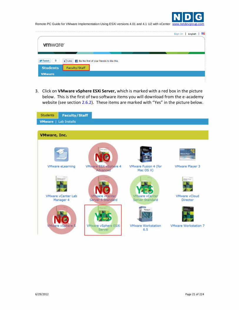
3. Click on VMware vSphere ESXi Server, which is marked with a red box in the picture
below. This is the first of two software items you will download from the e-academy website (see section 2.6.2). These items are marked with “Yes” in the picture below.
Remote PC Guide for VMware Implementation Using ESXi versions 4.01 and 4.1 U2 with vCenter www.netdevgroup.com
6/29/2012 Page 22 of 224
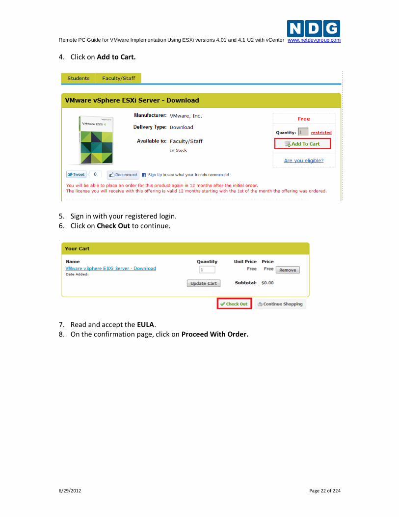
4. Click on Add to Cart.
5. Sign in with your registered login. 6. Click on Check Out to continue.
7. Read and accept the EULA. 8. On the confirmation page, click on Proceed With Order.
Remote PC Guide for VMware Implementation Using ESXi versions 4.01 and 4.1 U2 with vCenter www.netdevgroup.com
6/29/2012 Page 23 of 224
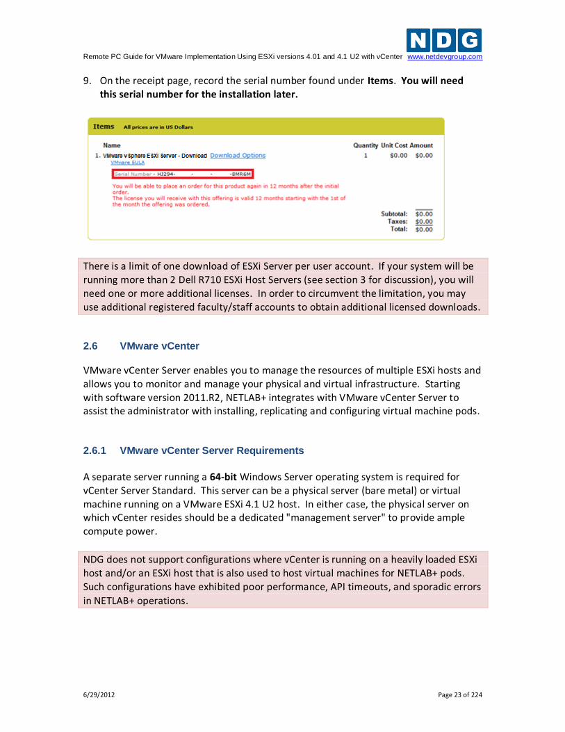
9. On the receipt page, record the serial number found under Items. You will need this serial number for the installation later.
There is a limit of one download of ESXi Server per user account. If your system will be running more than 2 Dell R710 ESXi Host Servers (see section 3 for discussion), you will need one or more additional licenses. In order to circumvent the limitation, you may use additional registered faculty/staff accounts to obtain additional licensed downloads.
2.6 VMware vCenter
VMware vCenter Server enables you to manage the resources of multiple ESXi hosts and allows you to monitor and manage your physical and virtual infrastructure. Starting with software version 2011.R2, NETLAB+ integrates with VMware vCenter Server to assist the administrator with installing, replicating and configuring virtual machine pods. 2.6.1 VMware vCenter Server Requirements
A separate server running a 64-bit Windows Server operating system is required for vCenter Server Standard. This server can be a physical server (bare metal) or virtual machine running on a VMware ESXi 4.1 U2 host. In either case, the physical server on which vCenter resides should be a dedicated "management server" to provide ample compute power.
NDG does not support configurations where vCenter is running on a heavily loaded ESXi host and/or an ESXi host that is also used to host virtual machines for NETLAB+ pods. Such configurations have exhibited poor performance, API timeouts, and sporadic errors
in NETLAB+ operations.
Remote PC Guide for VMware Implementation Using ESXi versions 4.01 and 4.1 U2 with vCenter www.netdevgroup.com
6/29/2012 Page 24 of 224
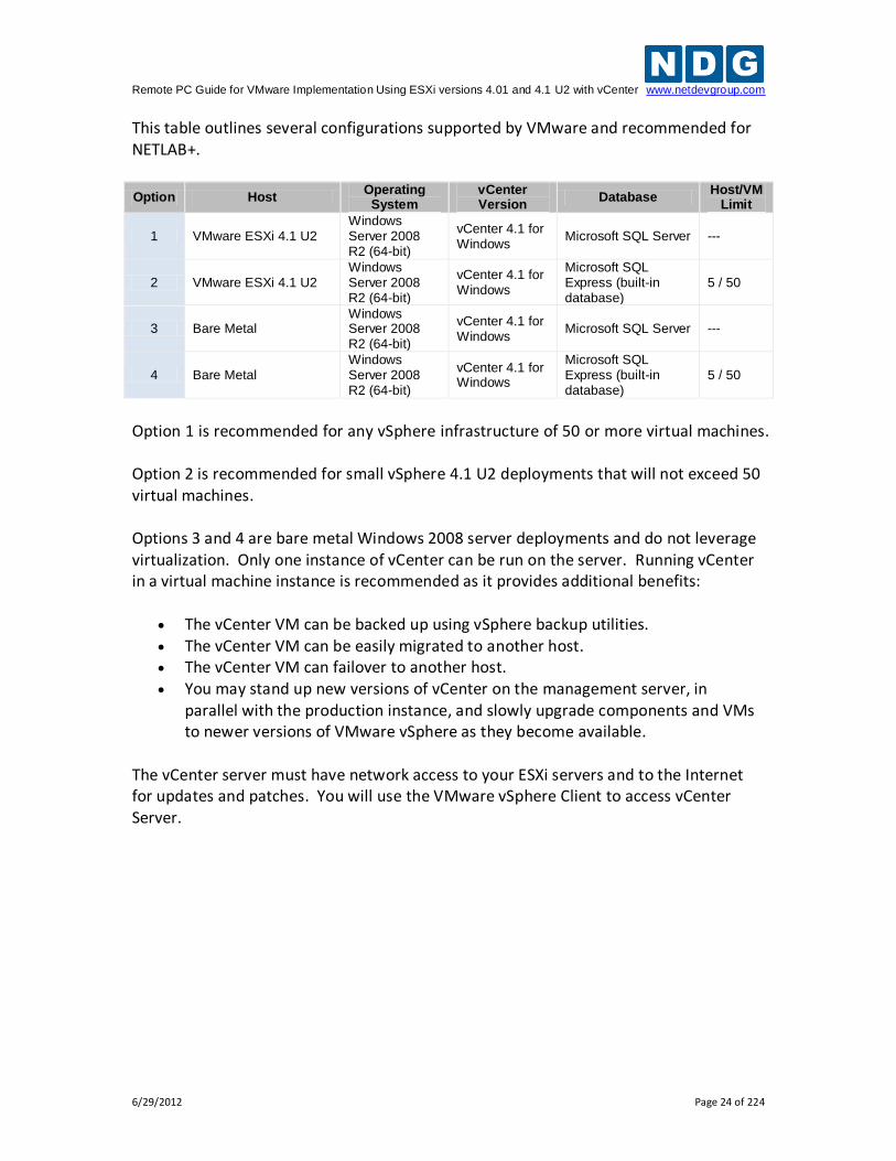
This table outlines several configurations supported by VMware and recommended for NETLAB+.
Option Host Operating
System vCenter Version
Database Host/VM
Limit
1 VMware ESXi 4.1 U2 Windows Server 2008 R2 (64-bit)
vCenter 4.1 for Windows
Microsoft SQL Server ---
2 VMware ESXi 4.1 U2 Windows Server 2008 R2 (64-bit)
vCenter 4.1 for Windows
Microsoft SQL Express (built-in database)
5 / 50
3 Bare Metal Windows Server 2008 R2 (64-bit)
vCenter 4.1 for Windows
Microsoft SQL Server ---
4 Bare Metal Windows Server 2008 R2 (64-bit)
vCenter 4.1 for Windows
Microsoft SQL Express (built-in database)
5 / 50
Option 1 is recommended for any vSphere infrastructure of 50 or more virtual machines. Option 2 is recommended for small vSphere 4.1 U2 deployments that will not exceed 50 virtual machines. Options 3 and 4 are bare metal Windows 2008 server deployments and do not leverage virtualization. Only one instance of vCenter can be run on the server. Running vCenter in a virtual machine instance is recommended as it provides additional benefits:
The vCenter VM can be backed up using vSphere backup utilities. The vCenter VM can be easily migrated to another host. The vCenter VM can failover to another host. You may stand up new versions of vCenter on the management server, in
parallel with the production instance, and slowly upgrade components and VMs to newer versions of VMware vSphere as they become available.
The vCenter server must have network access to your ESXi servers and to the Internet for updates and patches. You will use the VMware vSphere Client to access vCenter Server.
Remote PC Guide for VMware Implementation Using ESXi versions 4.01 and 4.1 U2 with vCenter www.netdevgroup.com
6/29/2012 Page 25 of 224
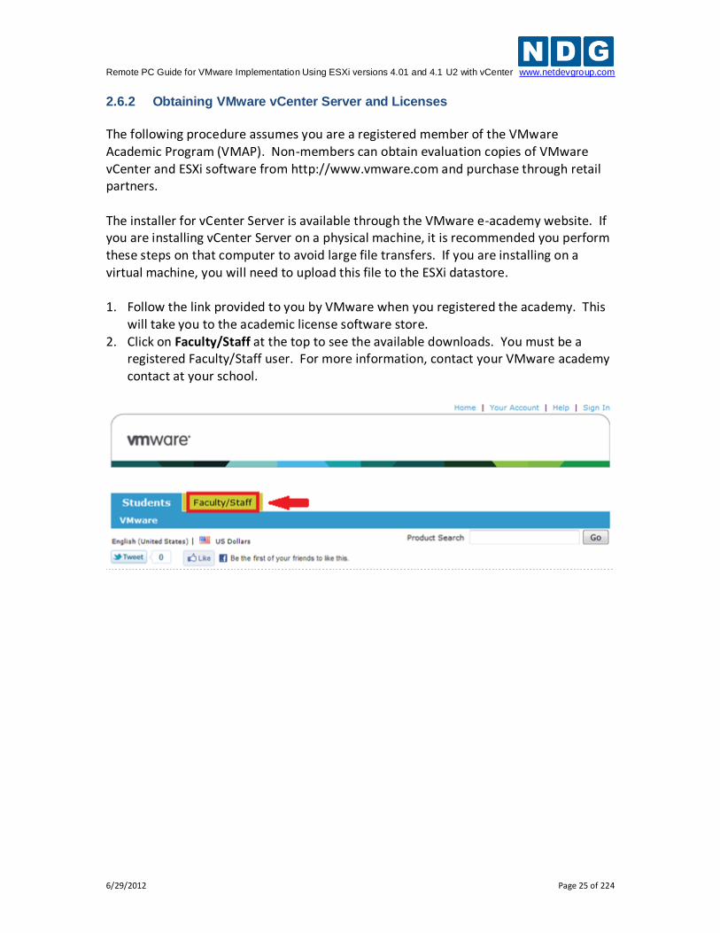
2.6.2 Obtaining VMware vCenter Server and Licenses
The following procedure assumes you are a registered member of the VMware Academic Program (VMAP). Non-members can obtain evaluation copies of VMware vCenter and ESXi software from http://www.vmware.com and purchase through retail partners. The installer for vCenter Server is available through the VMware e-academy website. If you are installing vCenter Server on a physical machine, it is recommended you perform these steps on that computer to avoid large file transfers. If you are installing on a virtual machine, you will need to upload this file to the ESXi datastore. 1. Follow the link provided to you by VMware when you registered the academy. This
will take you to the academic license software store. 2. Click on Faculty/Staff at the top to see the available downloads. You must be a
registered Faculty/Staff user. For more information, contact your VMware academy contact at your school.
Remote PC Guide for VMware Implementation Using ESXi versions 4.01 and 4.1 U2 with vCenter www.netdevgroup.com
6/29/2012 Page 26 of 224
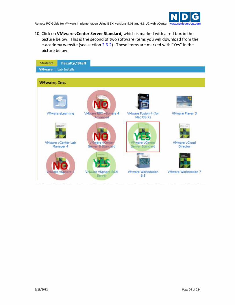
10. Click on VMware vCenter Server Standard, which is marked with a red box in the picture below. This is the second of two software items you will download from the e-academy website (see section 2.6.2). These items are marked with “Yes” in the picture below.
Remote PC Guide for VMware Implementation Using ESXi versions 4.01 and 4.1 U2 with vCenter www.netdevgroup.com
6/29/2012 Page 27 of 224
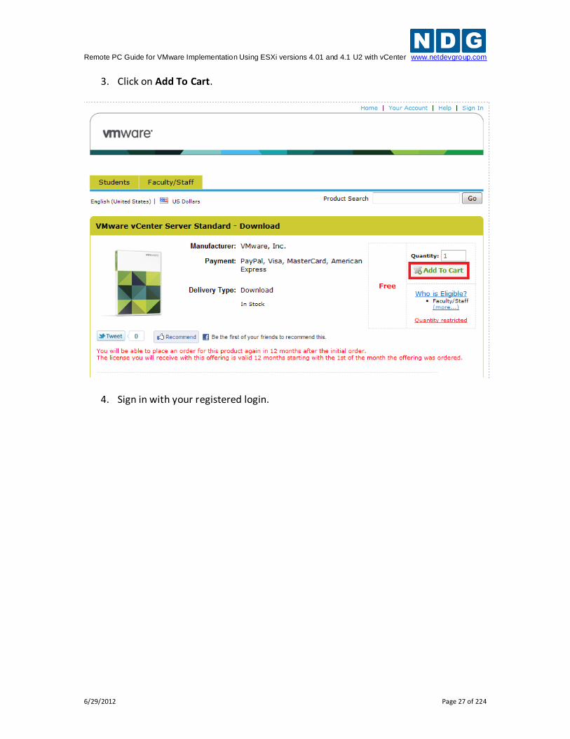
3. Click on Add To Cart.
4. Sign in with your registered login.
Remote PC Guide for VMware Implementation Using ESXi versions 4.01 and 4.1 U2 with vCenter www.netdevgroup.com
6/29/2012 Page 28 of 224
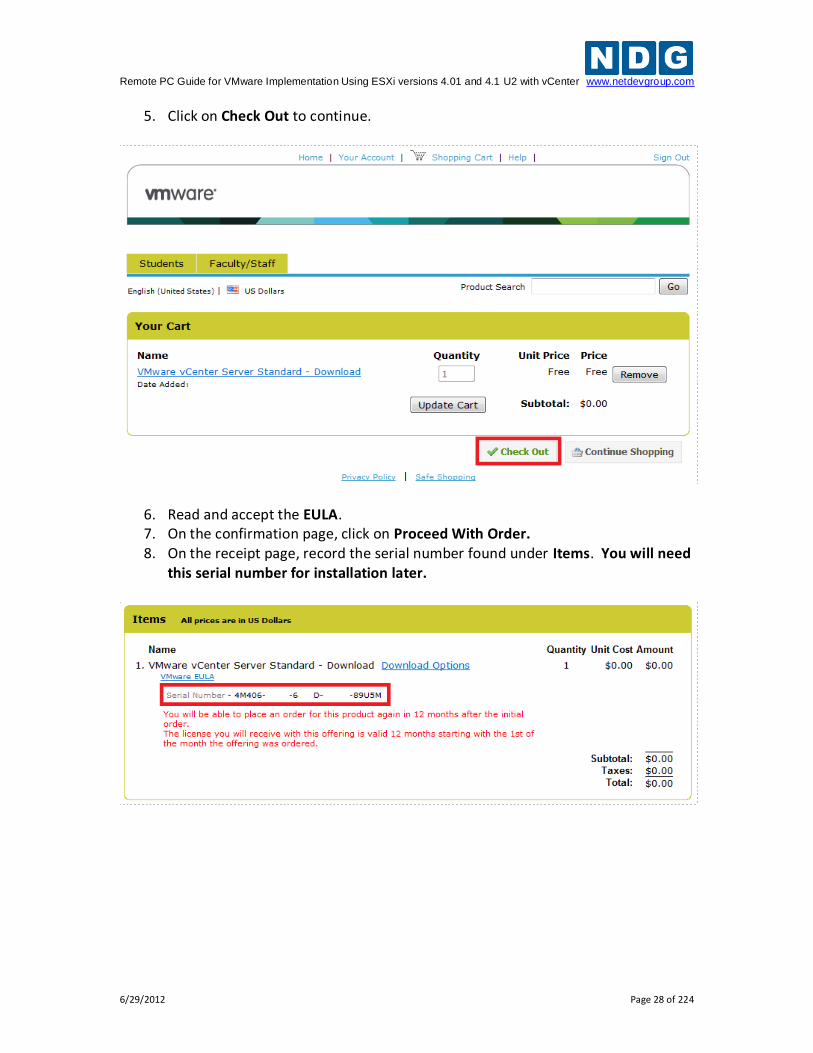
5. Click on Check Out to continue.
6. Read and accept the EULA. 7. On the confirmation page, click on Proceed With Order. 8. On the receipt page, record the serial number found under Items. You will need
this serial number for installation later.
Remote PC Guide for VMware Implementation Using ESXi versions 4.01 and 4.1 U2 with vCenter www.netdevgroup.com
6/29/2012 Page 29 of 224
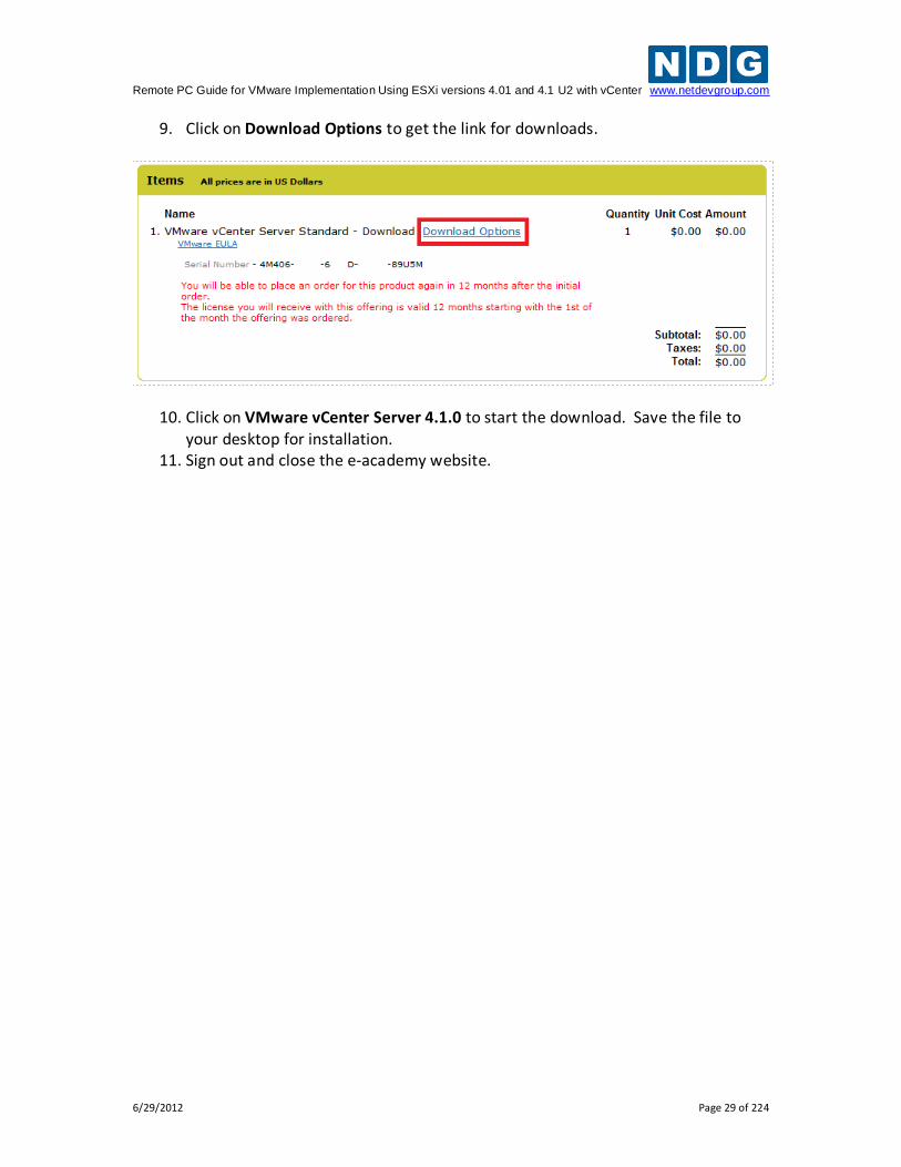
9. Click on Download Options to get the link for downloads.
10. Click on VMware vCenter Server 4.1.0 to start the download. Save the file to your desktop for installation.
11. Sign out and close the e-academy website.
Remote PC Guide for VMware Implementation Using ESXi versions 4.01 and 4.1 U2 with vCenter www.netdevgroup.com
6/29/2012 Page 30 of 224
2.7 Networking Models
The NETLAB+ server, vCenter server and ESXi hosts may be single-homed or dual-homed depending on your requirements. This guide documents three common networking configurations:
Single-Homed Networking
Dual-Homed Networking
Secure+ Networking Please review each configuration to determine which one best suits your needs. Choose only one of these configurations, then perform the corresponding setup tasks .
The NETLAB+ server, vCenter server and ESXi hosts should be geographically co-located. If Single-Homed (outside) networking is used, all components should be connected by 100Mb/s or higher speed LAN. NDG does not support split server configurations that
traverse a WAN and/or configurations that place firewalls between these servers.
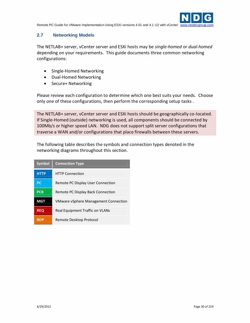
The following table describes the symbols and connection types denoted in the networking diagrams throughout this section.
Symbol Connection Type
HTTP HTTP Connection
PC Remote PC Display User Connection
PCB Remote PC Display Back Connection
MGT VMware vSphere Management Connection
REQ Real Equipment Traffic on VLANs
RDP Remote Desktop Protocol
Remote PC Guide for VMware Implementation Using ESXi versions 4.01 and 4.1 U2 with vCenter www.netdevgroup.com
6/29/2012 Page 31 of 224
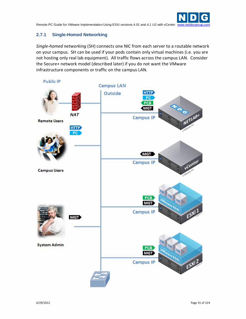
2.7.1 Single-Homed Networking
Single-homed networking (SH) connects one NIC from each server to a routable network on your campus. SH can be used if your pods contain only virtual machines (i.e. you are not hosting only real lab equipment). All traffic flows across the campus LAN. Consider the Secure+ network model (described later) if you do not want the VMware infrastructure components or traffic on the campus LAN.
Remote PC Guide for VMware Implementation Using ESXi versions 4.01 and 4.1 U2 with vCenter www.netdevgroup.com
6/29/2012 Page 32 of 224
SH does not require NETLAB+ control switches. A 1Gb/second switch port is highly recommended for each server connection. This will provide optimal bandwidth for remote display connections and virtual machine cloning operations between hosts. 2.7.1.1 Single-Homed Setup Tasks
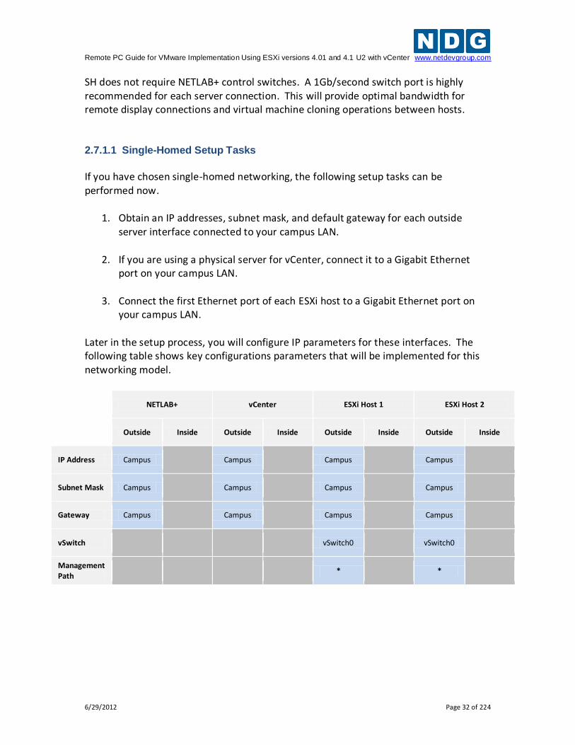
If you have chosen single-homed networking, the following setup tasks can be performed now.
1. Obtain an IP addresses, subnet mask, and default gateway for each outside server interface connected to your campus LAN.
2. If you are using a physical server for vCenter, connect it to a Gigabit Ethernet port on your campus LAN.
3. Connect the first Ethernet port of each ESXi host to a Gigabit Ethernet port on your campus LAN.
Later in the setup process, you will configure IP parameters for these interfaces. The following table shows key configurations parameters that will be implemented for this networking model.
NETLAB+ vCenter ESXi Host 1 ESXi Host 2
Outside Inside Outside Inside Outside Inside Outside Inside
IP Address Campus
Campus
Campus
Campus
Subnet Mask Campus
Campus
Campus
Campus
Gateway Campus
Campus
Campus
Campus
vSwitch
vSwitch0
vSwitch0
Management Path
*
*
Remote PC Guide for VMware Implementation Using ESXi versions 4.01 and 4.1 U2 with vCenter www.netdevgroup.com
6/29/2012 Page 33 of 224
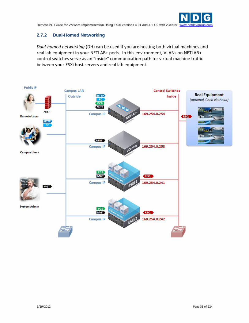
2.7.2 Dual-Homed Networking
Dual-homed networking (DH) can be used if you are hosting both virtual machines and real lab equipment in your NETLAB+ pods. In this environment, VLANs on NETLAB+ control switches serve as an "inside" communication path for virtual machine traffic between your ESXi host servers and real lab equipment.
Remote PC Guide for VMware Implementation Using ESXi versions 4.01 and 4.1 U2 with vCenter www.netdevgroup.com
6/29/2012 Page 34 of 224
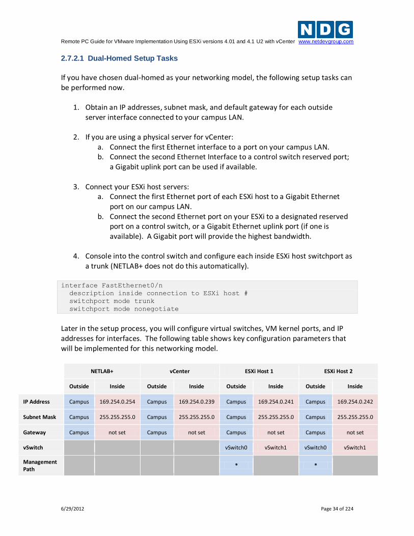
2.7.2.1 Dual-Homed Setup Tasks
If you have chosen dual-homed as your networking model, the following setup tasks can be performed now.
1. Obtain an IP addresses, subnet mask, and default gateway for each outside server interface connected to your campus LAN.
2. If you are using a physical server for vCenter: a. Connect the first Ethernet interface to a port on your campus LAN. b. Connect the second Ethernet Interface to a control switch reserved port;
a Gigabit uplink port can be used if available.
3. Connect your ESXi host servers: a. Connect the first Ethernet port of each ESXi host to a Gigabit Ethernet
port on our campus LAN. b. Connect the second Ethernet port on your ESXi to a designated reserved
port on a control switch, or a Gigabit Ethernet uplink port (if one is available). A Gigabit port will provide the highest bandwidth.
4. Console into the control switch and configure each inside ESXi host switchport as
a trunk (NETLAB+ does not do this automatically). interface FastEthernet0/n
description inside connection to ESXi host #
switchport mode trunk
switchport mode nonegotiate
Later in the setup process, you will configure virtual switches, VM kernel ports, and IP addresses for interfaces. The following table shows key configuration parameters that will be implemented for this networking model.
NETLAB+ vCenter ESXi Host 1 ESXi Host 2
Outside Inside Outside Inside Outside Inside Outside Inside
IP Address Campus 169.254.0.254 Campus 169.254.0.239 Campus 169.254.0.241 Campus 169.254.0.242
Subnet Mask Campus 255.255.255.0 Campus 255.255.255.0 Campus 255.255.255.0 Campus 255.255.255.0
Gateway Campus not set Campus not set Campus not set Campus not set
vSwitch
vSwitch0 vSwitch1 vSwitch0 vSwitch1
Management Path
*
*
Remote PC Guide for VMware Implementation Using ESXi versions 4.01 and 4.1 U2 with vCenter www.netdevgroup.com
6/29/2012 Page 35 of 224
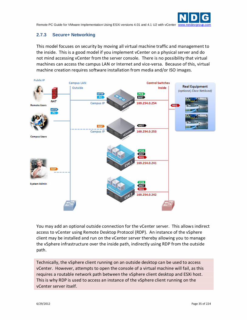
2.7.3 Secure+ Networking
This model focuses on security by moving all virtual machine traffic and management to the inside. This is a good model if you implement vCenter on a physical server and do not mind accessing vCenter from the server console. There is no possibility that virtual machines can access the campus LAN or Internet and vice-versa. Because of this, virtual machine creation requires software installation from media and/or ISO images.
You may add an optional outside connection for the vCenter server. This allows indirect access to vCenter using Remote Desktop Protocol (RDP). An instance of the vSphere client may be installed and run on the vCenter server thereby allowing you to manage the vSphere infrastructure over the inside path, indirectly using RDP from the outside path.
Technically, the vSphere client running on an outside desktop can be used to access vCenter. However, attempts to open the console of a virtual machine will fail, as this requires a routable network path between the vSphere client desktop and ESXi host. This is why RDP is used to access an instance of the vSphere client running on the
vCenter server itself.
Remote PC Guide for VMware Implementation Using ESXi versions 4.01 and 4.1 U2 with vCenter www.netdevgroup.com
6/29/2012 Page 36 of 224
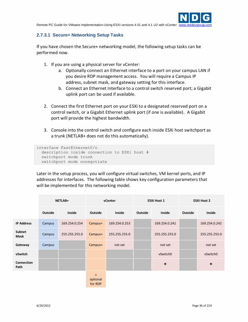
2.7.3.1 Secure+ Networking Setup Tasks
If you have chosen the Secure+ networking model, the following setup tasks can be performed now.
1. If you are using a physical server for vCenter: a. Optionally connect an Ethernet interface to a port on your campus LAN if
you desire RDP management access. You will require a Campus IP address, subnet mask, and gateway setting for this interface.
b. Connect an Ethernet Interface to a control switch reserved port; a Gigabit uplink port can be used if available.
2. Connect the first Ethernet port on your ESXi to a designated reserved port on a
control switch, or a Gigabit Ethernet uplink port (if one is available). A Gigabit port will provide the highest bandwidth.
3. Console into the control switch and configure each inside ESXi host switchport as a trunk (NETLAB+ does not do this automatically).
interface FastEthernet0/n
description inside connection to ESXi host #
switchport mode trunk
switchport mode nonegotiate
Later in the setup process, you will configure virtual switches, VM kernel ports, and IP addresses for interfaces. The following table shows key configuration parameters that will be implemented for this networking model.
NETLAB+ vCenter ESXi Host 1 ESXi Host 2
Outside Inside Outside Inside Outside Inside Outside Inside
IP Address Campus 169.254.0.254 Campus+ 169.254.0.253
169.254.0.241
169.254.0.242
Subnet Mask
Campus 255.255.255.0 Campus+ 255.255.255.0
255.255.255.0
255.255.255.0
Gateway Campus
Campus+ not set
not set
not set
vSwitch
vSwitch0
vSwitch0
Connection Path *
*
+ optional for RDP
Remote PC Guide for VMware Implementation Using ESXi versions 4.01 and 4.1 U2 with vCenter www.netdevgroup.com
6/29/2012 Page 37 of 224
2.8 Storage Area Networks
A storage area network (SAN) provides centralized shared storage for virtual machines and data. Sharing storage usually simplifies storage administration and adds flexibility since virtual machines can be migrated from one ESXi host to another without copying large files. NDG performs all testing on servers with Internal Direct Attached Storage (i.e. RAID arrays and RAID controllers directly attached to each). This is the configuration that most academic institutions are likely to find affordable and adopt. A Storage Area Network (SAN) is a dedicated network that provides access to consolidated, block level data storage that can be used for disk storage in a VMware vSphere environment. Currently NDG does not provide benchmarks, guidance or troubleshooting for SAN configurations. Our documentation may show an optional SAN in the environment; however, this is not a recommendation or requirement to deploy a SAN. NDG benchmarks and capacity planning guidance do not account for the additional latencies introduced by SAN.
When compared to Direct Attached Storage, a SAN may introduce additional I/O latency between ESXi server and disk. Therefore, a SAN may reduce the number of active VMs you can run on an ESXi host.
If you deploy a SAN, you should perform your own benchmarks and determine the number of active VMs you can host on your ESXi server. Your mileage may vary.
Always configure NETLAB+ Proactive Resource Awareness to ensure that the number of VMs that can be activated will remain within your predetermined performance limits.
Caution. Deployment of a SAN requires skill and planning. Performance of SAN solutions can vary greatly. NDG performance benchmarks are based on Direct Attached Storage (local disks connected to each ESXi hosts). Free SAN solutions may be attractive, but test results show I/O rates that are half or less than directly attached
SATA or SAS drives attached to the ESXi hosts.
Remote PC Guide for VMware Implementation Using ESXi versions 4.01 and 4.1 U2 with vCenter www.netdevgroup.com
6/29/2012 Page 38 of 224
3 VMware ESXi Server Setup
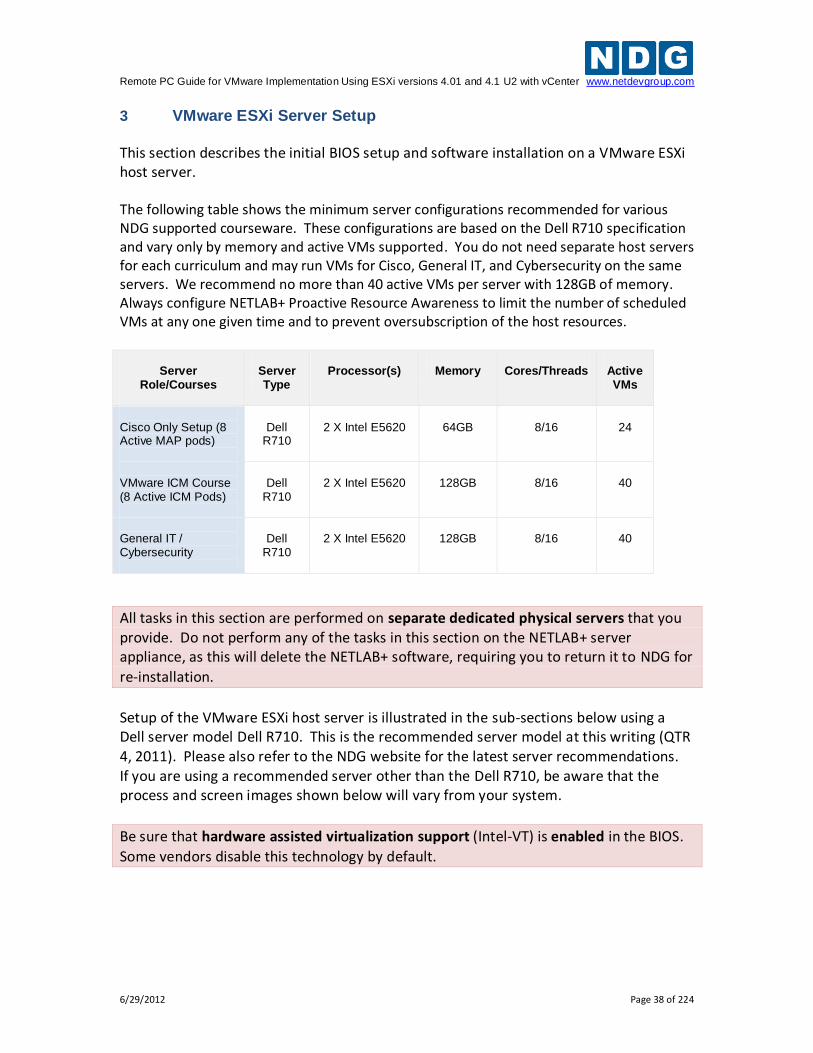
This section describes the initial BIOS setup and software installation on a VMware ESXi host server. The following table shows the minimum server configurations recommended for various NDG supported courseware. These configurations are based on the Dell R710 specification and vary only by memory and active VMs supported. You do not need separate host servers for each curriculum and may run VMs for Cisco, General IT, and Cybersecurity on the same servers. We recommend no more than 40 active VMs per server with 128GB of memory. Always configure NETLAB+ Proactive Resource Awareness to limit the number of scheduled VMs at any one given time and to prevent oversubscription of the host resources.
Server
Role/Courses
Server Type
Processor(s)
Memory
Cores/Threads
Active VMs
Cisco Only Setup (8 Active MAP pods)
Dell
R710
2 X Intel E5620
64GB
8/16
24
VMware ICM Course (8 Active ICM Pods)
Dell
R710
2 X Intel E5620
128GB
8/16
40
General IT / Cybersecurity
Dell
R710
2 X Intel E5620
128GB
8/16
40
All tasks in this section are performed on separate dedicated physical servers that you provide. Do not perform any of the tasks in this section on the NETLAB+ server appliance, as this will delete the NETLAB+ software, requiring you to return it to NDG for
re-installation.
Setup of the VMware ESXi host server is illustrated in the sub-sections below using a Dell server model Dell R710. This is the recommended server model at this writing (QTR 4, 2011). Please also refer to the NDG website for the latest server recommendations. If you are using a recommended server other than the Dell R710, be aware that the process and screen images shown below will vary from your system.
Be sure that hardware assisted virtualization support (Intel-VT) is enabled in the BIOS.
Some vendors disable this technology by default.
Remote PC Guide for VMware Implementation Using ESXi versions 4.01 and 4.1 U2 with vCenter www.netdevgroup.com
6/29/2012 Page 39 of 224
3.1 Preparing the ESXi Server
If you are using the recommended server from section 2.5, there are several BIOS settings and RAID configurations that you will need to make sure are set correctly. You must perform the steps detailed in the subsection below for every ESXi host server on your NETLAB+ system.
It is highly recommended that you read this section completely, prior to making changes
to your system.
3.1.1 DELL R710 BIOS System changes
Please verify that your system has the latest BIOS installed. You may obtain the latest
drivers and downloads for the Dell R710 from Dell’s website.
Instructions for changing BIOS settings:
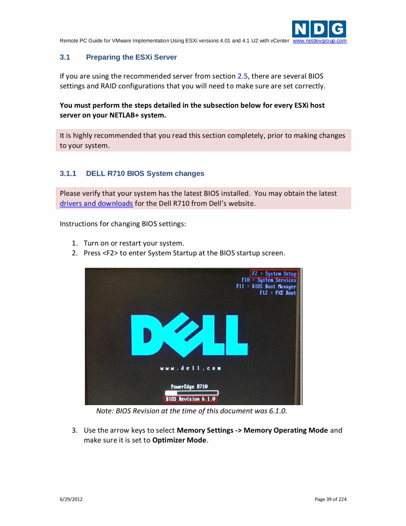
1. Turn on or restart your system. 2. Press <F2> to enter System Startup at the BIOS startup screen.
Note: BIOS Revision at the time of this document was 6.1.0.
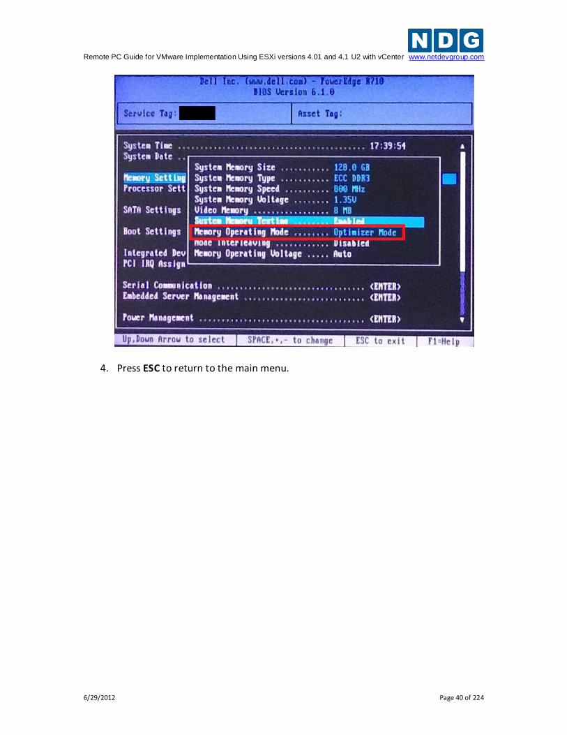
3. Use the arrow keys to select Memory Settings -> Memory Operating Mode and make sure it is set to Optimizer Mode.
Remote PC Guide for VMware Implementation Using ESXi versions 4.01 and 4.1 U2 with vCenter www.netdevgroup.com
6/29/2012 Page 40 of 224
4. Press ESC to return to the main menu.
Remote PC Guide for VMware Implementation Using ESXi versions 4.01 and 4.1 U2 with vCenter www.netdevgroup.com
6/29/2012 Page 41 of 224
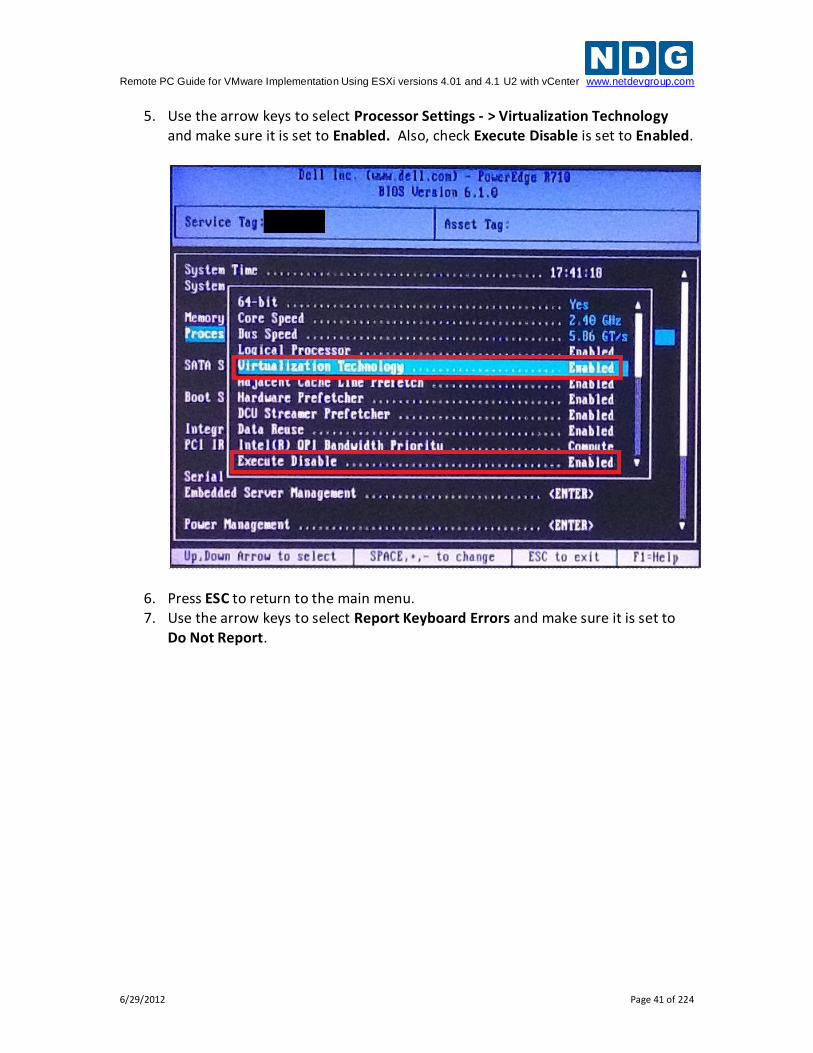
5. Use the arrow keys to select Processor Settings - > Virtualization Technology and make sure it is set to Enabled. Also, check Execute Disable is set to Enabled.
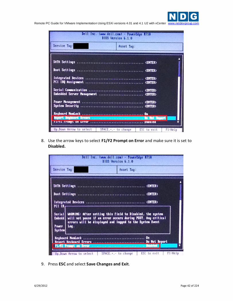
6. Press ESC to return to the main menu. 7. Use the arrow keys to select Report Keyboard Errors and make sure it is set to
Do Not Report.
Remote PC Guide for VMware Implementation Using ESXi versions 4.01 and 4.1 U2 with vCenter www.netdevgroup.com
6/29/2012 Page 42 of 224
8. Use the arrow keys to select F1/F2 Prompt on Error and make sure it is set to Disabled.
9. Press ESC and select Save Changes and Exit.
Remote PC Guide for VMware Implementation Using ESXi versions 4.01 and 4.1 U2 with vCenter www.netdevgroup.com
6/29/2012 Page 43 of 224
3.2 DELL R710 RAID Configuration
Redundant Array of Independent Disks (RAID) is designed to give the server redundancy and increased performance depending on the RAID type selected. The recommended and tested configuration is a RAID 5. The H700 RAID controller with 512MB cache is recommended and supported. The H200 is NOT supported. The H200 has exhibited poor performance and does not support RAID 5. Please see section 2.5.1 for details on hardware requirements. RAID 5 distributes error-correcting bits (parity) along with the data and requires all drives but one to be present to operate; the array is not destroyed by a single drive failure. Upon drive failure, any subsequent reads can be calculated from the distributed parity such that the drive failure is masked from the end user. However, a single drive failure results in reduced performance of the entire array until the failed drive has been replaced and the associated data rebuilt.
RAID 5 arrays may take several hours to initialize as the controller creates parity on the
drives. The 3x2TB drive configuration will take approximately 4 hours.
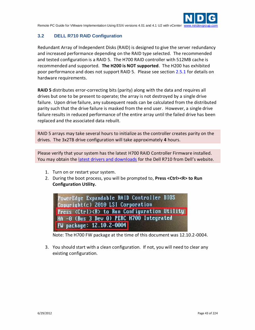
Please verify that your system has the latest H700 RAID Controller Firmware installed. You may obtain the latest drivers and downloads for the Dell R710 from Dell’s website.
1. Turn on or restart your system. 2. During the boot process, you will be prompted to, Press <Ctrl><R> to Run
Configuration Utility.
Note: The H700 FW package at the time of this document was 12.10.2-0004.
3. You should start with a clean configuration. If not, you will need to clear any existing configuration.
Remote PC Guide for VMware Implementation Using ESXi versions 4.01 and 4.1 U2 with vCenter www.netdevgroup.com
6/29/2012 Page 44 of 224
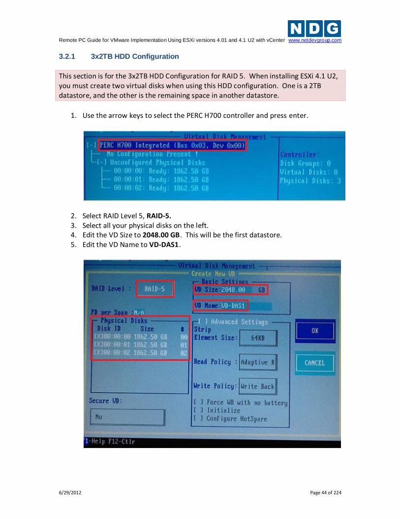
3.2.1 3x2TB HDD Configuration
This section is for the 3x2TB HDD Configuration for RAID 5. When installing ESXi 4.1 U2, you must create two virtual disks when using this HDD configuration. One is a 2TB datastore, and the other is the remaining space in another datastore.
1. Use the arrow keys to select the PERC H700 controller and press enter.
2. Select RAID Level 5, RAID-5. 3. Select all your physical disks on the left. 4. Edit the VD Size to 2048.00 GB. This will be the first datastore. 5. Edit the VD Name to VD-DAS1.
Remote PC Guide for VMware Implementation Using ESXi versions 4.01 and 4.1 U2 with vCenter www.netdevgroup.com
6/29/2012 Page 45 of 224
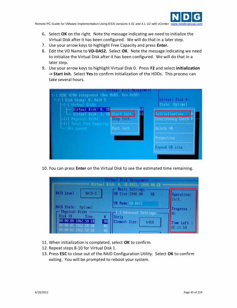
6. Select OK on the right. Note the message indicating we need to initialize the Virtual Disk after it has been configured. We will do that in a later step.
7. Use your arrow keys to highlight Free Capacity and press Enter. 8. Edit the VD Name to VD-DAS2. Select OK. Note the message indicating we need
to initialize the Virtual Disk after it has been configured. We will do that in a later step.
9. Use your arrow keys to highlight Virtual Disk 0. Press F2 and select initialization -> Start Init. Select Yes to confirm Initialization of the HDDs. This process can take several hours.
10. You can press Enter on the Virtual Disk to see the estimated time remaining.
11. When initialization is completed, select OK to confirm. 12. Repeat steps 8-10 for Virtual Disk 1. 13. Press ESC to close out of the RAID Configuration Utility. Select OK to confirm
exiting. You will be prompted to reboot your system.
Remote PC Guide for VMware Implementation Using ESXi versions 4.01 and 4.1 U2 with vCenter www.netdevgroup.com
6/29/2012 Page 46 of 224
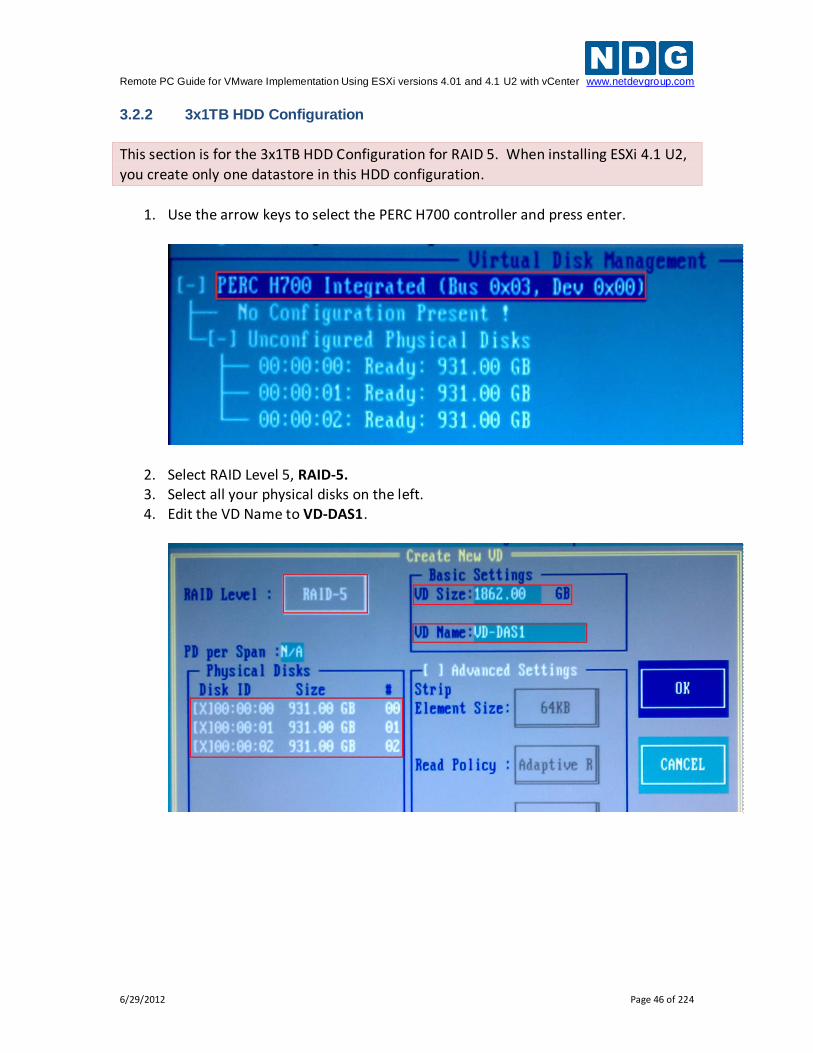
3.2.2 3x1TB HDD Configuration
This section is for the 3x1TB HDD Configuration for RAID 5. When installing ESXi 4.1 U2,
you create only one datastore in this HDD configuration.
1. Use the arrow keys to select the PERC H700 controller and press enter.
2. Select RAID Level 5, RAID-5. 3. Select all your physical disks on the left. 4. Edit the VD Name to VD-DAS1.
Remote PC Guide for VMware Implementation Using ESXi versions 4.01 and 4.1 U2 with vCenter www.netdevgroup.com
6/29/2012 Page 47 of 224
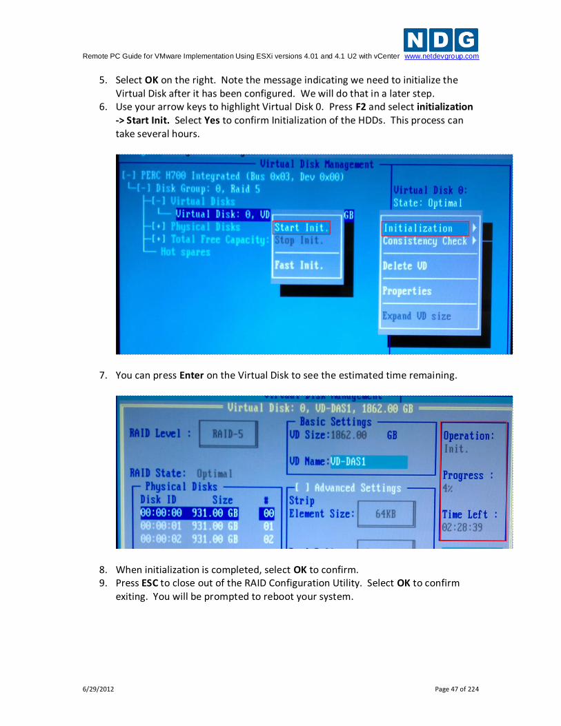
5. Select OK on the right. Note the message indicating we need to initialize the Virtual Disk after it has been configured. We will do that in a later step.
6. Use your arrow keys to highlight Virtual Disk 0. Press F2 and select initialization -> Start Init. Select Yes to confirm Initialization of the HDDs. This process can take several hours.
7. You can press Enter on the Virtual Disk to see the estimated time remaining.
8. When initialization is completed, select OK to confirm. 9. Press ESC to close out of the RAID Configuration Utility. Select OK to confirm
exiting. You will be prompted to reboot your system.
Remote PC Guide for VMware Implementation Using ESXi versions 4.01 and 4.1 U2 with vCenter www.netdevgroup.com
6/29/2012 Page 48 of 224
3.3 Installing ESXi on Host Server
This section will walk you through installing VMware ESXi to your host servers. Please note that the content in the images below will vary based on your system. The instructional steps are the same.
If you are using VMware ESXi 4.1 U2, please review the information in the Getting Started with ESXi Server Installable guide. You may use this guide as a reference for ESXi 4.1 Installable and ESXi 4.1 Embedded versions, with the exception that using ESXi Installable requires performing the installation procedure detailed on page 7, Install ESXi 4.1 using the Interactive Mode.
If you are using VMware ESXi 4.01, please review the information in the Getting Started with ESXi Server Installable guide. You may use this guide as a reference for ESXi 4.01 Installable and ESXi 4.01 Embedded versions, with the exception that using ESXi Installable requires performing the installation procedure detailed on page 9 Install ESXi 4.0. Keep in mind that the procedures detailed in this guide recommends and illustrates the use of ESXi 4.1.
If you have not done so already, burn a copy of the ESXi 4.1 Installable ISO.
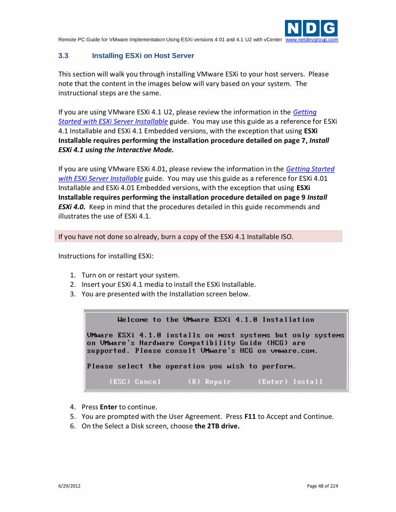
Instructions for installing ESXi:
1. Turn on or restart your system. 2. Insert your ESXi 4.1 media to install the ESXi Installable. 3. You are presented with the Installation screen below.
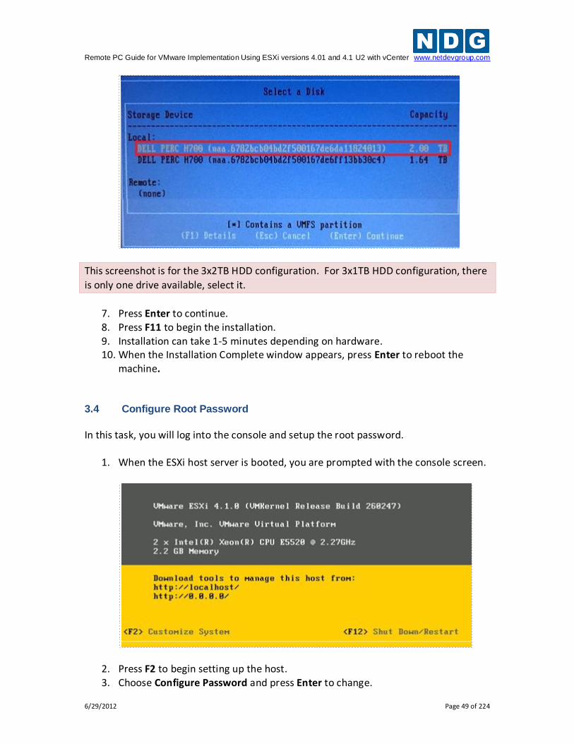
4. Press Enter to continue. 5. You are prompted with the User Agreement. Press F11 to Accept and Continue. 6. On the Select a Disk screen, choose the 2TB drive.
Remote PC Guide for VMware Implementation Using ESXi versions 4.01 and 4.1 U2 with vCenter www.netdevgroup.com
6/29/2012 Page 49 of 224
This screenshot is for the 3x2TB HDD configuration. For 3x1TB HDD configuration, there
is only one drive available, select it.
7. Press Enter to continue. 8. Press F11 to begin the installation. 9. Installation can take 1-5 minutes depending on hardware. 10. When the Installation Complete window appears, press Enter to reboot the
machine. 3.4 Configure Root Password
In this task, you will log into the console and setup the root password.
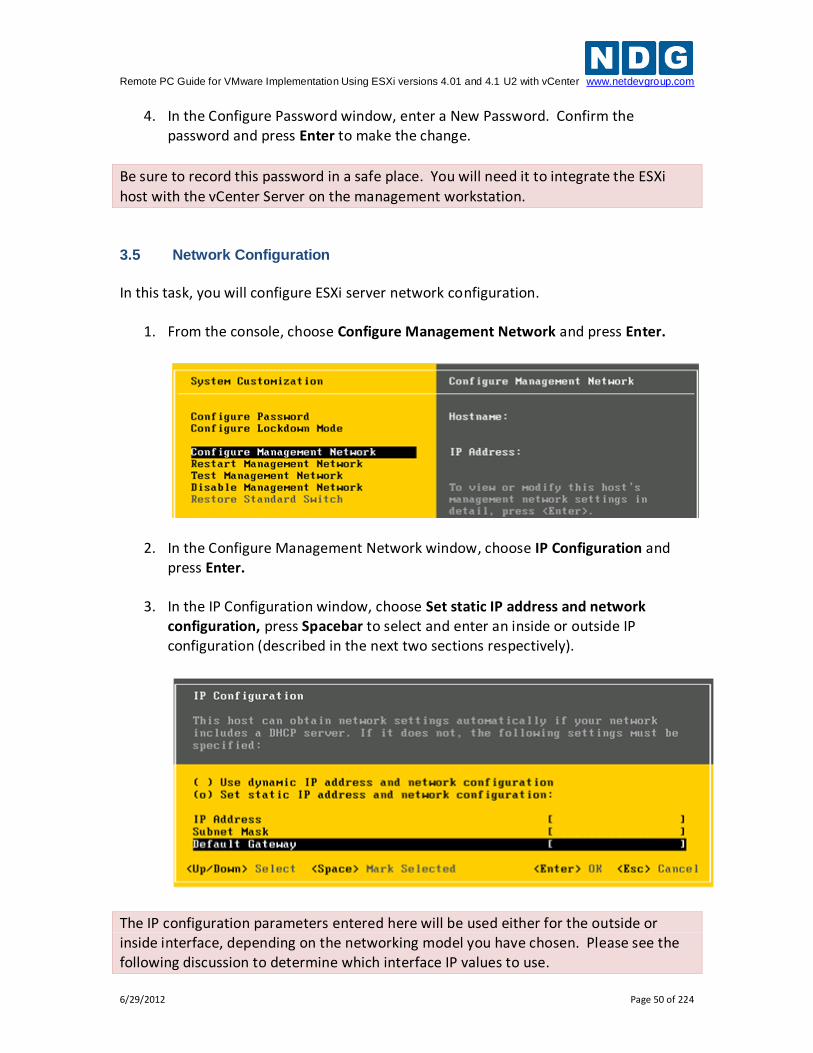
1. When the ESXi host server is booted, you are prompted with the console screen.
2. Press F2 to begin setting up the host. 3. Choose Configure Password and press Enter to change.
Remote PC Guide for VMware Implementation Using ESXi versions 4.01 and 4.1 U2 with vCenter www.netdevgroup.com
6/29/2012 Page 50 of 224
4. In the Configure Password window, enter a New Password. Confirm the password and press Enter to make the change.
Be sure to record this password in a safe place. You will need it to integrate the ESXi
host with the vCenter Server on the management workstation.
3.5 Network Configuration
In this task, you will configure ESXi server network configuration.
1. From the console, choose Configure Management Network and press Enter.
2. In the Configure Management Network window, choose IP Configuration and press Enter.
3. In the IP Configuration window, choose Set static IP address and network configuration, press Spacebar to select and enter an inside or outside IP configuration (described in the next two sections respectively).
The IP configuration parameters entered here will be used either for the outside or inside interface, depending on the networking model you have chosen. Please see the following discussion to determine which interface IP values to use.
Remote PC Guide for VMware Implementation Using ESXi versions 4.01 and 4.1 U2 with vCenter www.netdevgroup.com
6/29/2012 Page 51 of 224
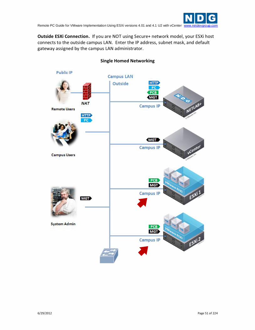
Outside ESXi Connection. If you are NOT using Secure+ network model, your ESXi host connects to the outside campus LAN. Enter the IP address, subnet mask, and default gateway assigned by the campus LAN administrator.
Single Homed Networking
Remote PC Guide for VMware Implementation Using ESXi versions 4.01 and 4.1 U2 with vCenter www.netdevgroup.com
6/29/2012 Page 52 of 224
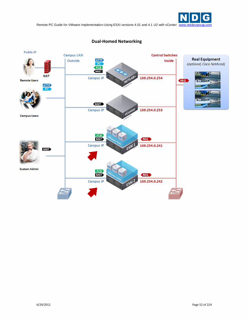
Dual-Homed Networking
Remote PC Guide for VMware Implementation Using ESXi versions 4.01 and 4.1 U2 with vCenter www.netdevgroup.com
6/29/2012 Page 53 of 224
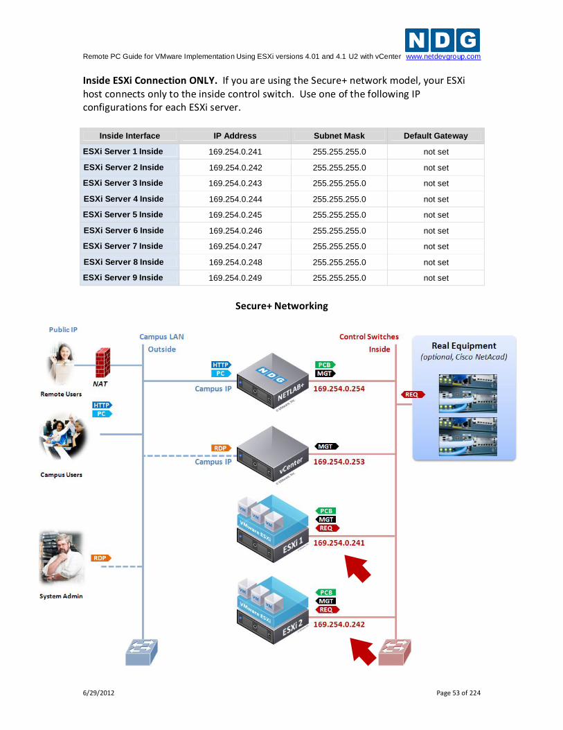
Inside ESXi Connection ONLY. If you are using the Secure+ network model, your ESXi host connects only to the inside control switch. Use one of the following IP configurations for each ESXi server.
Inside Interface IP Address Subnet Mask Default Gateway
ESXi Server 1 Inside 169.254.0.241 255.255.255.0 not set
ESXi Server 2 Inside 169.254.0.242 255.255.255.0 not set
ESXi Server 3 Inside 169.254.0.243 255.255.255.0 not set
ESXi Server 4 Inside 169.254.0.244 255.255.255.0 not set
ESXi Server 5 Inside 169.254.0.245 255.255.255.0 not set
ESXi Server 6 Inside 169.254.0.246 255.255.255.0 not set
ESXi Server 7 Inside 169.254.0.247 255.255.255.0 not set
ESXi Server 8 Inside 169.254.0.248 255.255.255.0 not set
ESXi Server 9 Inside 169.254.0.249 255.255.255.0 not set
Secure+ Networking
Remote PC Guide for VMware Implementation Using ESXi versions 4.01 and 4.1 U2 with vCenter www.netdevgroup.com
6/29/2012 Page 54 of 224
4. Press Enter to confirm changes and return to the Configure Management Network window.
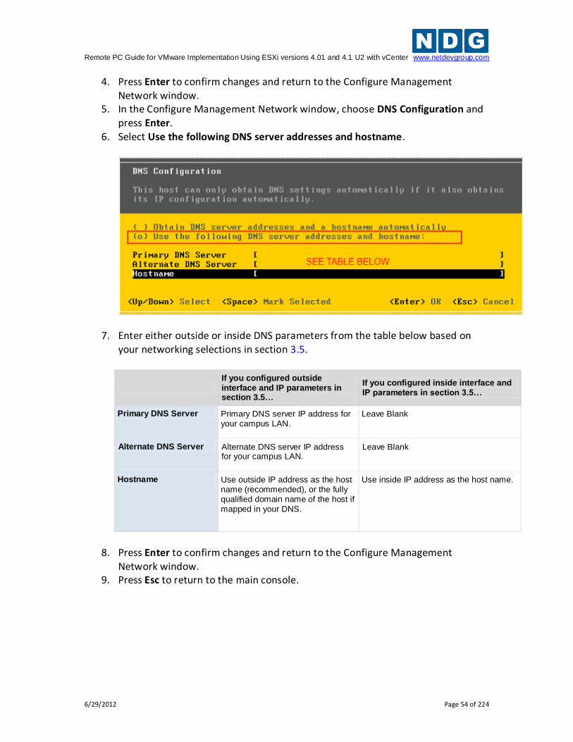
5. In the Configure Management Network window, choose DNS Configuration and press Enter.
6. Select Use the following DNS server addresses and hostname.
7. Enter either outside or inside DNS parameters from the table below based on your networking selections in section 3.5.
If you configured outside interface and IP parameters in section 3.5…
If you configured inside interface and IP parameters in section 3.5…
Primary DNS Server Primary DNS server IP address for your campus LAN.
Leave Blank
Alternate DNS Server Alternate DNS server IP address for your campus LAN.
Leave Blank
Hostname Use outside IP address as the host name (recommended), or the fully qualified domain name of the host if mapped in your DNS.
Use inside IP address as the host name.
8. Press Enter to confirm changes and return to the Configure Management
Network window. 9. Press Esc to return to the main console.
Remote PC Guide for VMware Implementation Using ESXi versions 4.01 and 4.1 U2 with vCenter www.netdevgroup.com
6/29/2012 Page 55 of 224
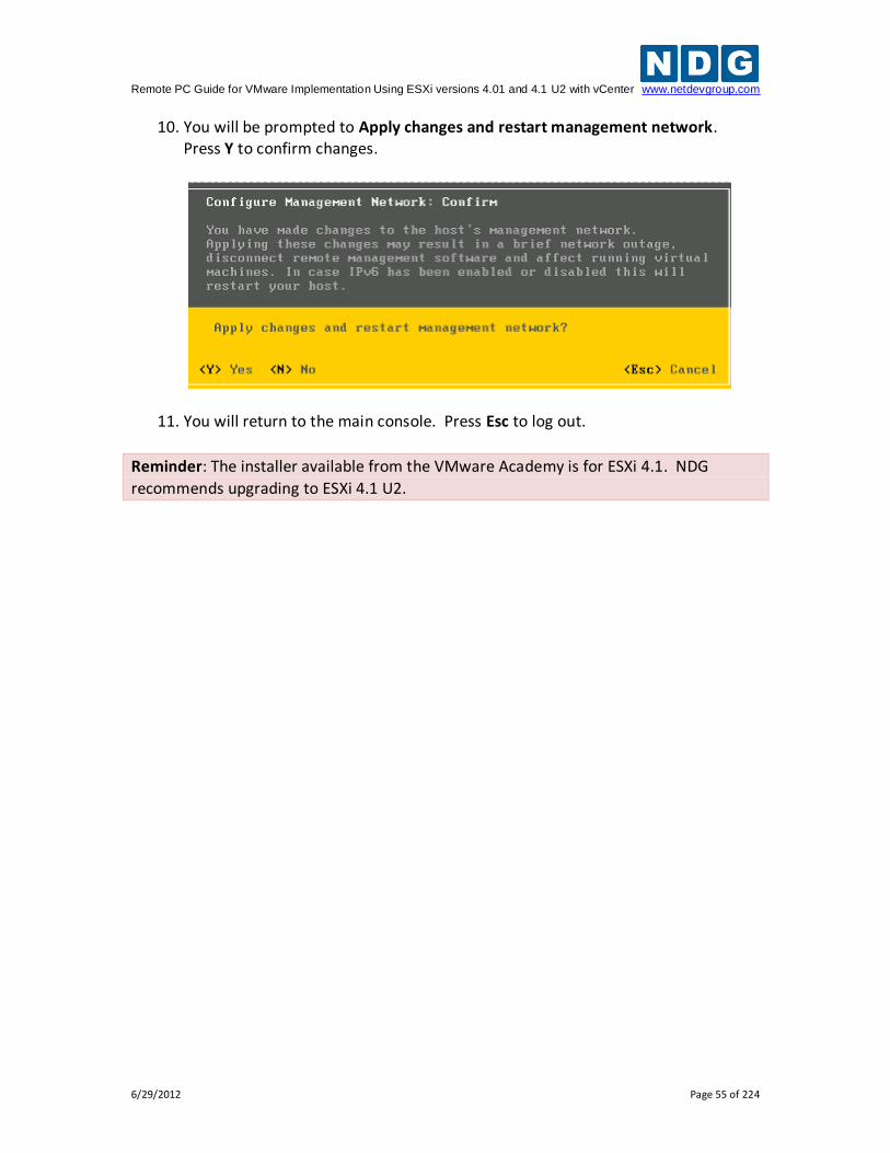
10. You will be prompted to Apply changes and restart management network. Press Y to confirm changes.
11. You will return to the main console. Press Esc to log out.
Reminder: The installer available from the VMware Academy is for ESXi 4.1. NDG
recommends upgrading to ESXi 4.1 U2.
Remote PC Guide for VMware Implementation Using ESXi versions 4.01 and 4.1 U2 with vCenter www.netdevgroup.com
6/29/2012 Page 56 of 224
4 VMware vCenter Server Setup In this section, you will setup the vCenter server and related utilities. A separate server running a 64-bit Windows Server operating system is required for vCenter Server Standard. This server can be a physical server (bare metal) or virtual machine running on a VMware ESXi 4.1 U2 host. In either case, the physical server on which vCenter resides should be a dedicated "management server" to provide ample compute power. VMware vCenter server requires at least two CPU cores.
NDG does not support configurations where vCenter is running on a heavily loaded ESXi host and/or an ESXi host that is also used to host virtual machines for NETLAB+ pods. Such configurations have exhibited poor performance, API timeouts, and sporadic errors
in NETLAB+ operations.
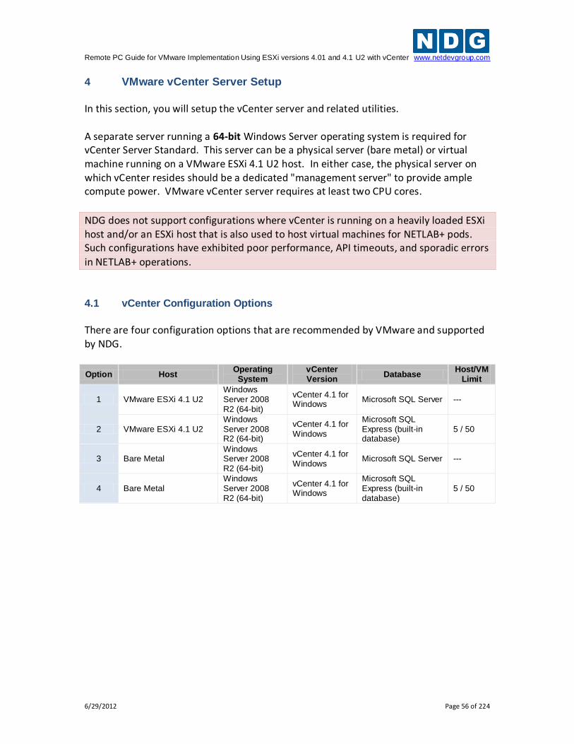
4.1 vCenter Configuration Options
There are four configuration options that are recommended by VMware and supported by NDG.
Option Host Operating
System vCenter Version
Database Host/VM
Limit
1 VMware ESXi 4.1 U2 Windows Server 2008 R2 (64-bit)
vCenter 4.1 for Windows
Microsoft SQL Server ---
2 VMware ESXi 4.1 U2 Windows Server 2008 R2 (64-bit)
vCenter 4.1 for Windows
Microsoft SQL Express (built-in database)
5 / 50
3 Bare Metal Windows Server 2008 R2 (64-bit)
vCenter 4.1 for Windows
Microsoft SQL Server ---
4 Bare Metal Windows Server 2008 R2 (64-bit)
vCenter 4.1 for Windows
Microsoft SQL Express (built-in database)
5 / 50
Remote PC Guide for VMware Implementation Using ESXi versions 4.01 and 4.1 U2 with vCenter www.netdevgroup.com
6/29/2012 Page 57 of 224
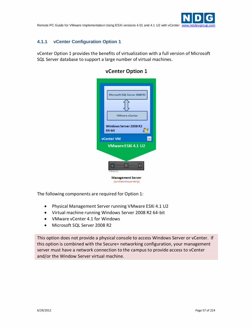
4.1.1 vCenter Configuration Option 1
vCenter Option 1 provides the benefits of virtualization with a full version of Microsoft SQL Server database to support a large number of virtual machines.
The following components are required for Option 1:
Physical Management Server running VMware ESXi 4.1 U2
Virtual machine running Windows Server 2008 R2 64-bit
VMware vCenter 4.1 for Windows
Microsoft SQL Server 2008 R2
This option does not provide a physical console to access Windows Server or vCenter. If this option is combined with the Secure+ networking configuration, your management server must have a network connection to the campus to provide access to vCenter
and/or the Window Server virtual machine.
Remote PC Guide for VMware Implementation Using ESXi versions 4.01 and 4.1 U2 with vCenter www.netdevgroup.com
6/29/2012 Page 58 of 224
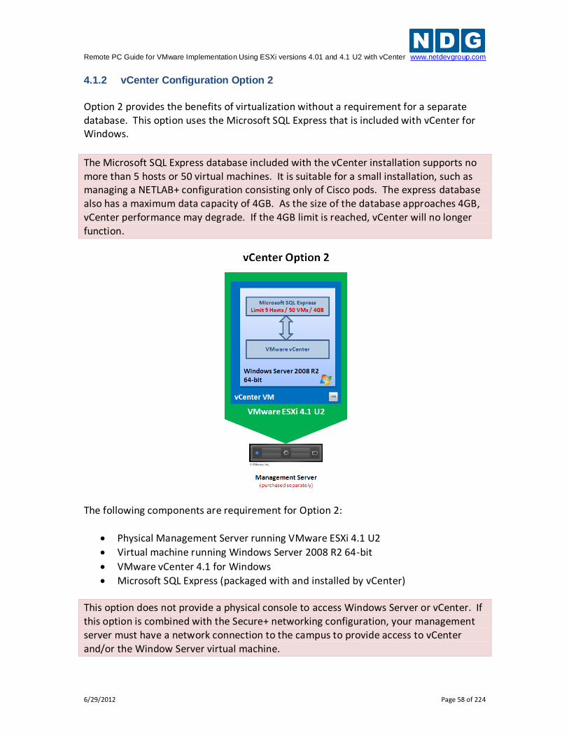
4.1.2 vCenter Configuration Option 2
Option 2 provides the benefits of virtualization without a requirement for a separate database. This option uses the Microsoft SQL Express that is included with vCenter for Windows.
The Microsoft SQL Express database included with the vCenter installation supports no more than 5 hosts or 50 virtual machines. It is suitable for a small installation, such as managing a NETLAB+ configuration consisting only of Cisco pods. The express database also has a maximum data capacity of 4GB. As the size of the database approaches 4GB, vCenter performance may degrade. If the 4GB limit is reached, vCenter will no longer function.
The following components are requirement for Option 2:
Physical Management Server running VMware ESXi 4.1 U2
Virtual machine running Windows Server 2008 R2 64-bit
VMware vCenter 4.1 for Windows
Microsoft SQL Express (packaged with and installed by vCenter)
This option does not provide a physical console to access Windows Server or vCenter. If this option is combined with the Secure+ networking configuration, your management server must have a network connection to the campus to provide access to vCenter and/or the Window Server virtual machine.
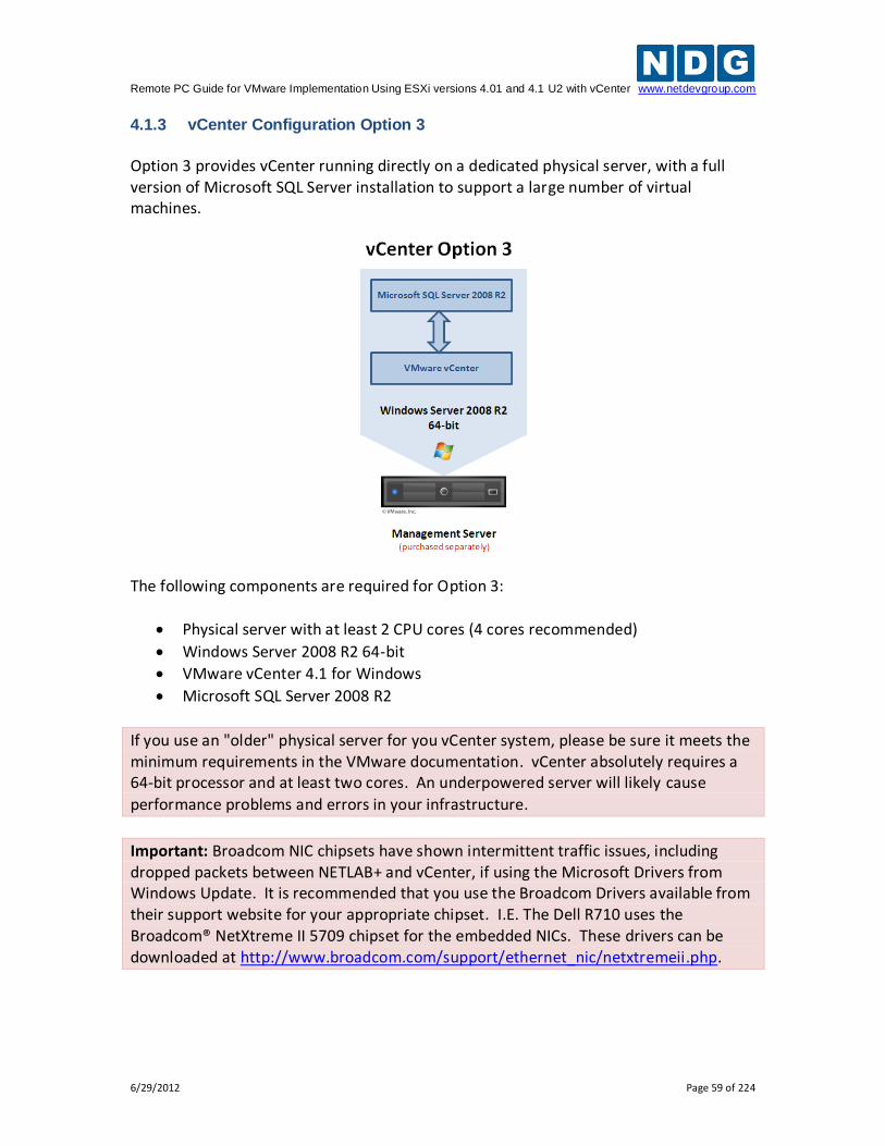
Remote PC Guide for VMware Implementation Using ESXi versions 4.01 and 4.1 U2 with vCenter www.netdevgroup.com
6/29/2012 Page 59 of 224
4.1.3 vCenter Configuration Option 3
Option 3 provides vCenter running directly on a dedicated physical server, with a full version of Microsoft SQL Server installation to support a large number of virtual machines.
The following components are required for Option 3:
Physical server with at least 2 CPU cores (4 cores recommended)
Windows Server 2008 R2 64-bit
VMware vCenter 4.1 for Windows
Microsoft SQL Server 2008 R2
If you use an "older" physical server for you vCenter system, please be sure it meets the minimum requirements in the VMware documentation. vCenter absolutely requires a 64-bit processor and at least two cores. An underpowered server will likely cause
performance problems and errors in your infrastructure.
Important: Broadcom NIC chipsets have shown intermittent traffic issues, including dropped packets between NETLAB+ and vCenter, if using the Microsoft Drivers from Windows Update. It is recommended that you use the Broadcom Drivers available from their support website for your appropriate chipset. I.E. The Dell R710 uses the Broadcom® NetXtreme II 5709 chipset for the embedded NICs. These drivers can be downloaded at http://www.broadcom.com/support/ethernet_nic/netxtremeii.php.
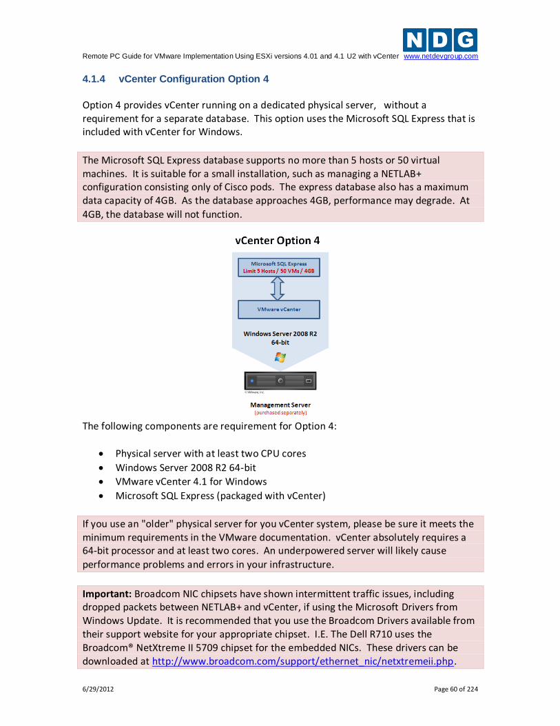
Remote PC Guide for VMware Implementation Using ESXi versions 4.01 and 4.1 U2 with vCenter www.netdevgroup.com
6/29/2012 Page 60 of 224
4.1.4 vCenter Configuration Option 4
Option 4 provides vCenter running on a dedicated physical server, without a requirement for a separate database. This option uses the Microsoft SQL Express that is included with vCenter for Windows.
The Microsoft SQL Express database supports no more than 5 hosts or 50 virtual machines. It is suitable for a small installation, such as managing a NETLAB+ configuration consisting only of Cisco pods. The express database also has a maximum data capacity of 4GB. As the database approaches 4GB, performance may degrade. At
4GB, the database will not function.
The following components are requirement for Option 4:
Physical server with at least two CPU cores
Windows Server 2008 R2 64-bit
VMware vCenter 4.1 for Windows
Microsoft SQL Express (packaged with vCenter)
If you use an "older" physical server for you vCenter system, please be sure it meets the minimum requirements in the VMware documentation. vCenter absolutely requires a 64-bit processor and at least two cores. An underpowered server will likely cause
performance problems and errors in your infrastructure.
Important: Broadcom NIC chipsets have shown intermittent traffic issues, including dropped packets between NETLAB+ and vCenter, if using the Microsoft Drivers from Windows Update. It is recommended that you use the Broadcom Drivers available from their support website for your appropriate chipset. I.E. The Dell R710 uses the Broadcom® NetXtreme II 5709 chipset for the embedded NICs. These drivers can be downloaded at http://www.broadcom.com/support/ethernet_nic/netxtremeii.php.
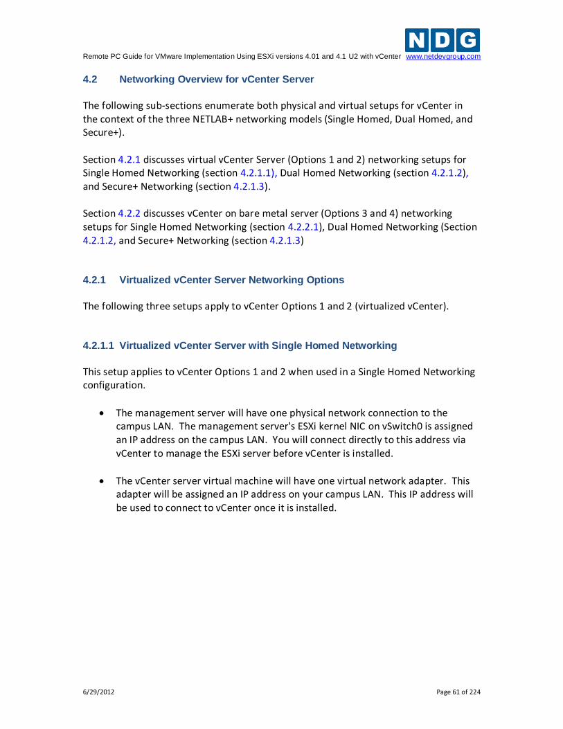
Remote PC Guide for VMware Implementation Using ESXi versions 4.01 and 4.1 U2 with vCenter www.netdevgroup.com
6/29/2012 Page 61 of 224
4.2 Networking Overview for vCenter Server
The following sub-sections enumerate both physical and virtual setups for vCenter in the context of the three NETLAB+ networking models (Single Homed, Dual Homed, and Secure+). Section 4.2.1 discusses virtual vCenter Server (Options 1 and 2) networking setups for Single Homed Networking (section 4.2.1.1), Dual Homed Networking (section 4.2.1.2), and Secure+ Networking (section 4.2.1.3). Section 4.2.2 discusses vCenter on bare metal server (Options 3 and 4) networking setups for Single Homed Networking (section 4.2.2.1), Dual Homed Networking (Section 4.2.1.2, and Secure+ Networking (section 4.2.1.3) 4.2.1 Virtualized vCenter Server Networking Options
The following three setups apply to vCenter Options 1 and 2 (virtualized vCenter). 4.2.1.1 Virtualized vCenter Server with Single Homed Networking
This setup applies to vCenter Options 1 and 2 when used in a Single Homed Networking configuration.
The management server will have one physical network connection to the campus LAN. The management server's ESXi kernel NIC on vSwitch0 is assigned an IP address on the campus LAN. You will connect directly to this address via vCenter to manage the ESXi server before vCenter is installed.
The vCenter server virtual machine will have one virtual network adapter. This adapter will be assigned an IP address on your campus LAN. This IP address will be used to connect to vCenter once it is installed.
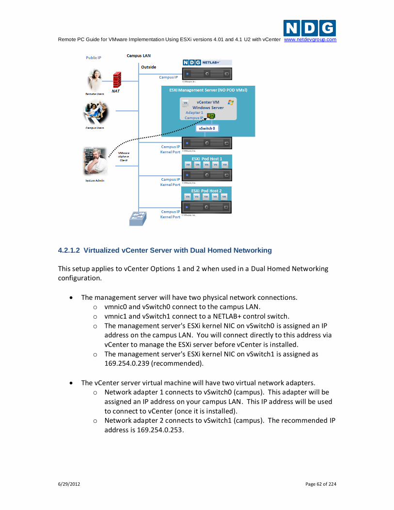
Remote PC Guide for VMware Implementation Using ESXi versions 4.01 and 4.1 U2 with vCenter www.netdevgroup.com
6/29/2012 Page 62 of 224
4.2.1.2 Virtualized vCenter Server with Dual Homed Networking
This setup applies to vCenter Options 1 and 2 when used in a Dual Homed Networking configuration.
The management server will have two physical network connections. o vmnic0 and vSwitch0 connect to the campus LAN. o vmnic1 and vSwitch1 connect to a NETLAB+ control switch. o The management server's ESXi kernel NIC on vSwitch0 is assigned an IP
address on the campus LAN. You will connect directly to this address via vCenter to manage the ESXi server before vCenter is installed.
o The management server's ESXi kernel NIC on vSwitch1 is assigned as 169.254.0.239 (recommended).
The vCenter server virtual machine will have two virtual network adapters. o Network adapter 1 connects to vSwitch0 (campus). This adapter will be
assigned an IP address on your campus LAN. This IP address will be used to connect to vCenter (once it is installed).
o Network adapter 2 connects to vSwitch1 (campus). The recommended IP address is 169.254.0.253.
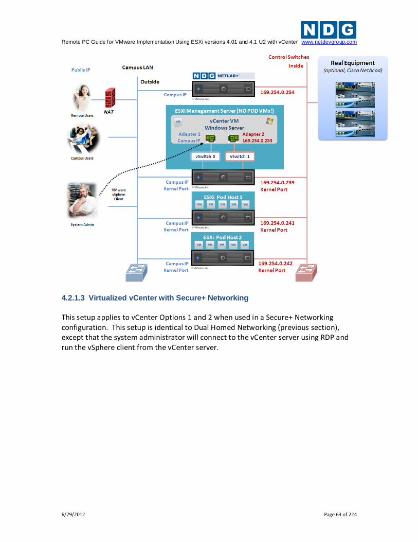
Remote PC Guide for VMware Implementation Using ESXi versions 4.01 and 4.1 U2 with vCenter www.netdevgroup.com
6/29/2012 Page 63 of 224
4.2.1.3 Virtualized vCenter with Secure+ Networking
This setup applies to vCenter Options 1 and 2 when used in a Secure+ Networking configuration. This setup is identical to Dual Homed Networking (previous section), except that the system administrator will connect to the vCenter server using RDP and run the vSphere client from the vCenter server.
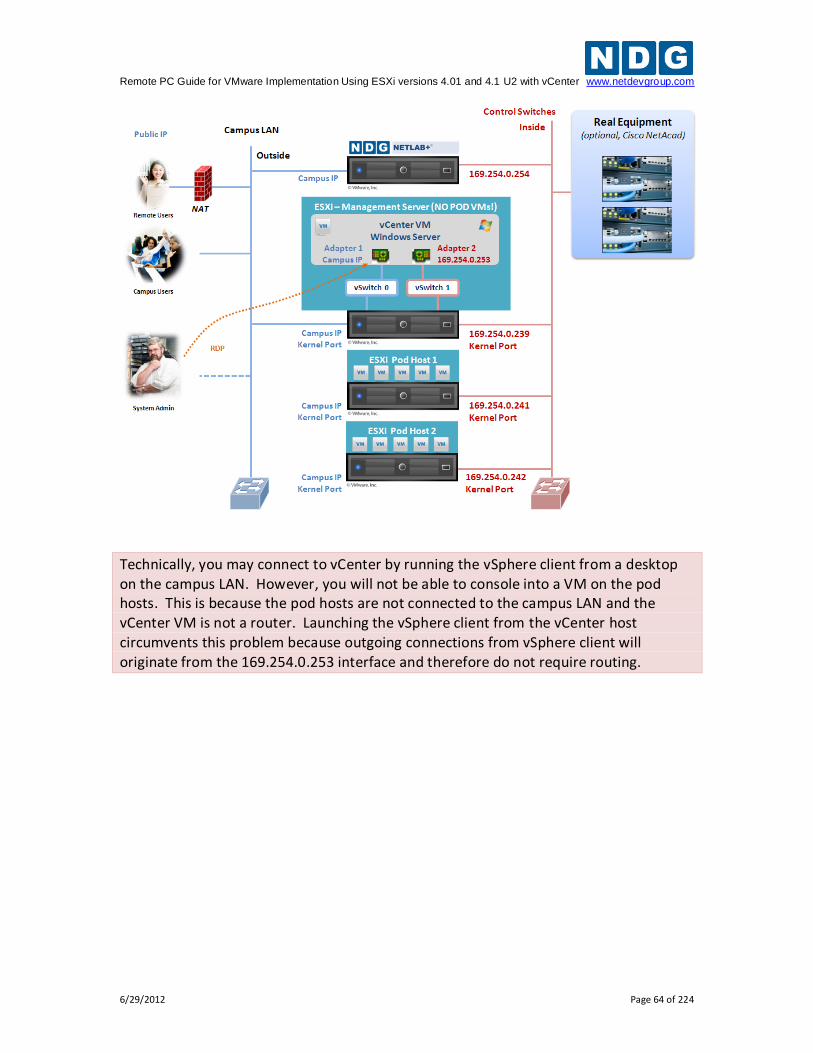
Remote PC Guide for VMware Implementation Using ESXi versions 4.01 and 4.1 U2 with vCenter www.netdevgroup.com
6/29/2012 Page 64 of 224
Technically, you may connect to vCenter by running the vSphere client from a desktop on the campus LAN. However, you will not be able to console into a VM on the pod hosts. This is because the pod hosts are not connected to the campus LAN and the vCenter VM is not a router. Launching the vSphere client from the vCenter host circumvents this problem because outgoing connections from vSphere client will originate from the 169.254.0.253 interface and therefore do not require routing.
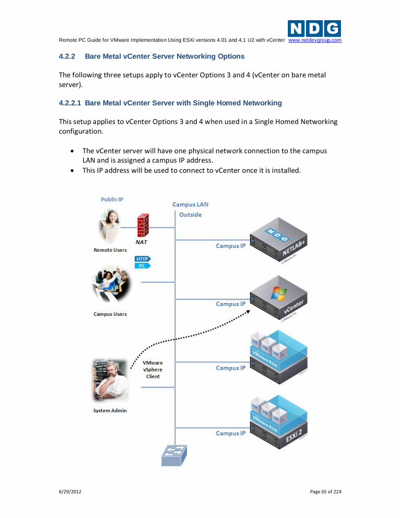
Remote PC Guide for VMware Implementation Using ESXi versions 4.01 and 4.1 U2 with vCenter www.netdevgroup.com
6/29/2012 Page 65 of 224
4.2.2 Bare Metal vCenter Server Networking Options
The following three setups apply to vCenter Options 3 and 4 (vCenter on bare metal server). 4.2.2.1 Bare Metal vCenter Server with Single Homed Networking
This setup applies to vCenter Options 3 and 4 when used in a Single Homed Networking configuration.
The vCenter server will have one physical network connection to the campus LAN and is assigned a campus IP address.
This IP address will be used to connect to vCenter once it is installed.
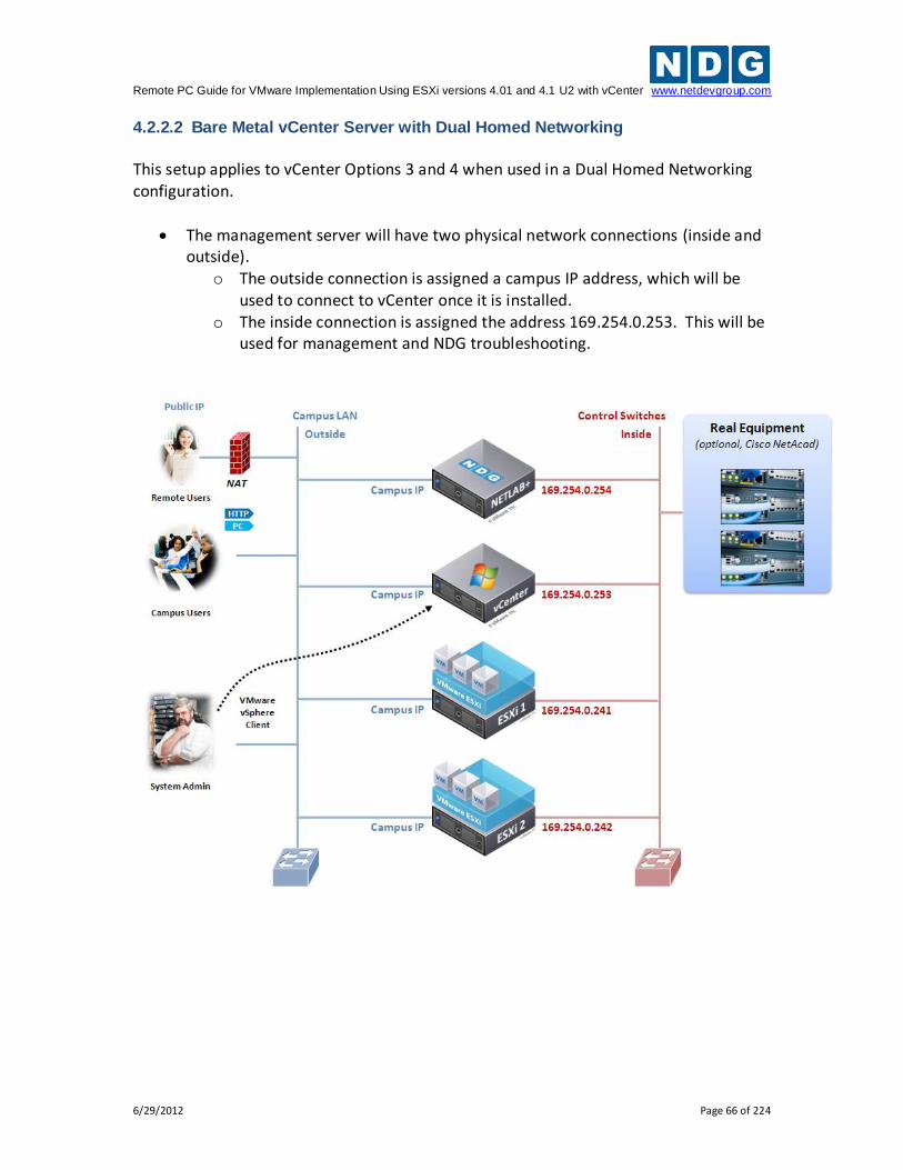
Remote PC Guide for VMware Implementation Using ESXi versions 4.01 and 4.1 U2 with vCenter www.netdevgroup.com
6/29/2012 Page 66 of 224
4.2.2.2 Bare Metal vCenter Server with Dual Homed Networking
This setup applies to vCenter Options 3 and 4 when used in a Dual Homed Networking configuration.
The management server will have two physical network connections (inside and outside).
o The outside connection is assigned a campus IP address, which will be used to connect to vCenter once it is installed.
o The inside connection is assigned the address 169.254.0.253. This will be used for management and NDG troubleshooting.
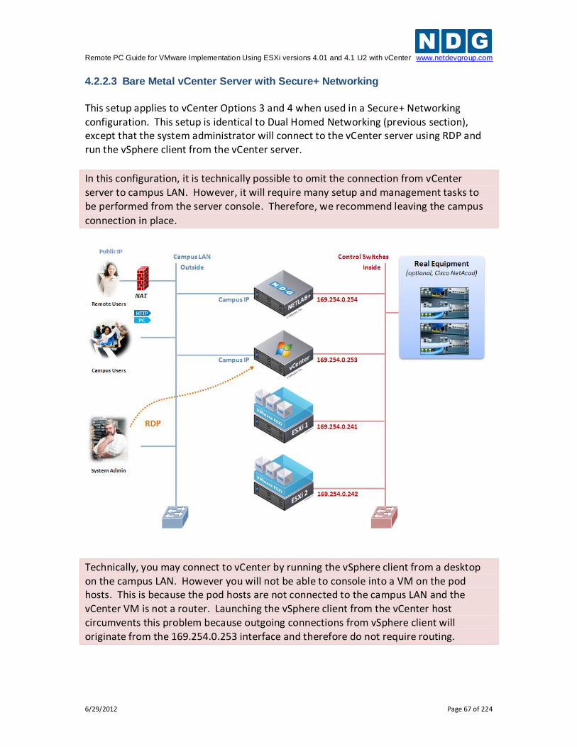
Remote PC Guide for VMware Implementation Using ESXi versions 4.01 and 4.1 U2 with vCenter www.netdevgroup.com
6/29/2012 Page 67 of 224
4.2.2.3 Bare Metal vCenter Server with Secure+ Networking
This setup applies to vCenter Options 3 and 4 when used in a Secure+ Networking configuration. This setup is identical to Dual Homed Networking (previous section), except that the system administrator will connect to the vCenter server using RDP and run the vSphere client from the vCenter server.
In this configuration, it is technically possible to omit the connection from vCenter server to campus LAN. However, it will require many setup and management tasks to be performed from the server console. Therefore, we recommend leaving the campus
connection in place.
Technically, you may connect to vCenter by running the vSphere client from a desktop on the campus LAN. However you will not be able to console into a VM on the pod hosts. This is because the pod hosts are not connected to the campus LAN and the vCenter VM is not a router. Launching the vSphere client from the vCenter host circumvents this problem because outgoing connections from vSphere client will originate from the 169.254.0.253 interface and therefore do not require routing.
Remote PC Guide for VMware Implementation Using ESXi versions 4.01 and 4.1 U2 with vCenter www.netdevgroup.com
6/29/2012 Page 68 of 224
4.3 Configure Management Server
This task applies to (virtual) vCenter Options 1 and 2 only.
1. Install ESXi 4.1 U2 on your management server using guidance from section 3. 2. Open the vSphere client from a workstation on your campus network. 3. Connect directly to the IP address of the management server. 4. Enter the username of root. 5. Enter the password of used during ESXi installation. 6. Create a new virtual machine for vCenter using the following parameters.
vCPUs 2
vRAM 4GB or higher if using Microsoft SQL Server (Option 1) 3GB or higher if using Microsoft SQL Express (Option 2)
Network Adapters 1 for Single Homed Network configuration 2 for Dual Homed Networking configuration 2 for Secure+ Networking configuration
7. Bind network adapter 1 to the vSwitch that is connected to the campus LAN.
This is usually vSwitch0 and is called "VM network" in the pull down menu by default.
8. Bind network adapter 2 (if Dual Homed or Secure+) to the vSwitch that connects with the NETLAB+ control switch. This is typically vSwitch1.
4.4 Install Windows Server 2008 R2 64-bit
At this time, you should install Windows Server 2008 R2 64-bit.
For a virtual vCenter configuration (Option 1 or 2), you will install Windows Server on the virtual machine created in section 4.3.
For a bare metal vCenter configuration (Option 3 or 4), you will install Windows Server on the physical server you have dedicated for vCenter.
Older NETLAB+ servers have CD-ROM drive. Please DO NOT accidently install Windows Server on the NETLAB+ server! This will overwrite the NETLAB+ operating system and software.
Apply all operating system updates are applied before continuing.
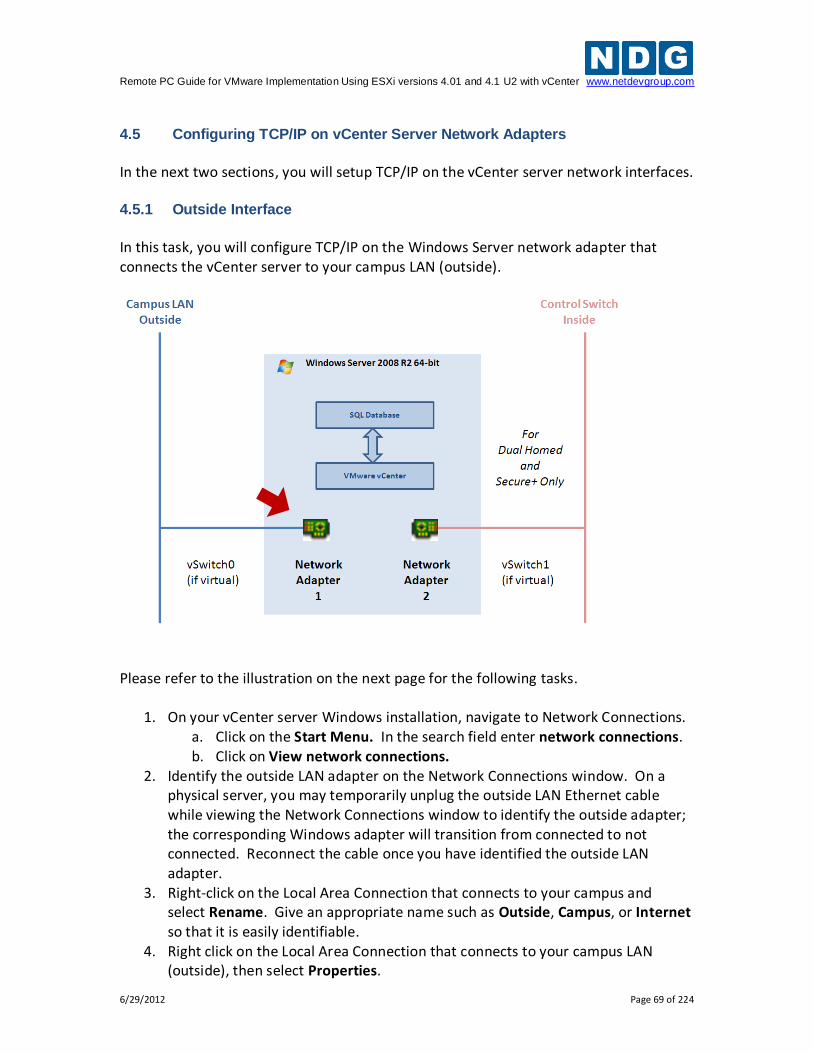
Remote PC Guide for VMware Implementation Using ESXi versions 4.01 and 4.1 U2 with vCenter www.netdevgroup.com
6/29/2012 Page 69 of 224
4.5 Configuring TCP/IP on vCenter Server Network Adapters
In the next two sections, you will setup TCP/IP on the vCenter server network interfaces. 4.5.1 Outside Interface
In this task, you will configure TCP/IP on the Windows Server network adapter that connects the vCenter server to your campus LAN (outside).
Please refer to the illustration on the next page for the following tasks.
1. On your vCenter server Windows installation, navigate to Network Connections. a. Click on the Start Menu. In the search field enter network connections. b. Click on View network connections.
2. Identify the outside LAN adapter on the Network Connections window. On a physical server, you may temporarily unplug the outside LAN Ethernet cable while viewing the Network Connections window to identify the outside adapter; the corresponding Windows adapter will transition from connected to not connected. Reconnect the cable once you have identified the outside LAN adapter.
3. Right-click on the Local Area Connection that connects to your campus and select Rename. Give an appropriate name such as Outside, Campus, or Internet so that it is easily identifiable.
4. Right click on the Local Area Connection that connects to your campus LAN (outside), then select Properties.
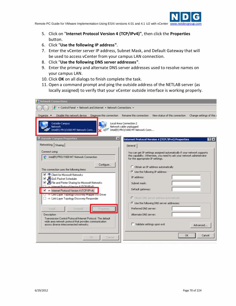
Remote PC Guide for VMware Implementation Using ESXi versions 4.01 and 4.1 U2 with vCenter www.netdevgroup.com
6/29/2012 Page 70 of 224
5. Click on "Internet Protocol Version 4 (TCP/IPv4)", then click the Properties button.
6. Click "Use the following IP address". 7. Enter the vCenter server IP address, Subnet Mask, and Default Gateway that will
be used to access vCenter from your campus LAN connection. 8. Click "Use the following DNS server addresses". 9. Enter the primary and alternate DNS server addresses used to resolve names on
your campus LAN. 10. Click OK on all dialogs to finish complete the task. 11. Open a command prompt and ping the outside address of the NETLAB server (as
locally assigned) to verify that your vCenter outside interface is working properly.
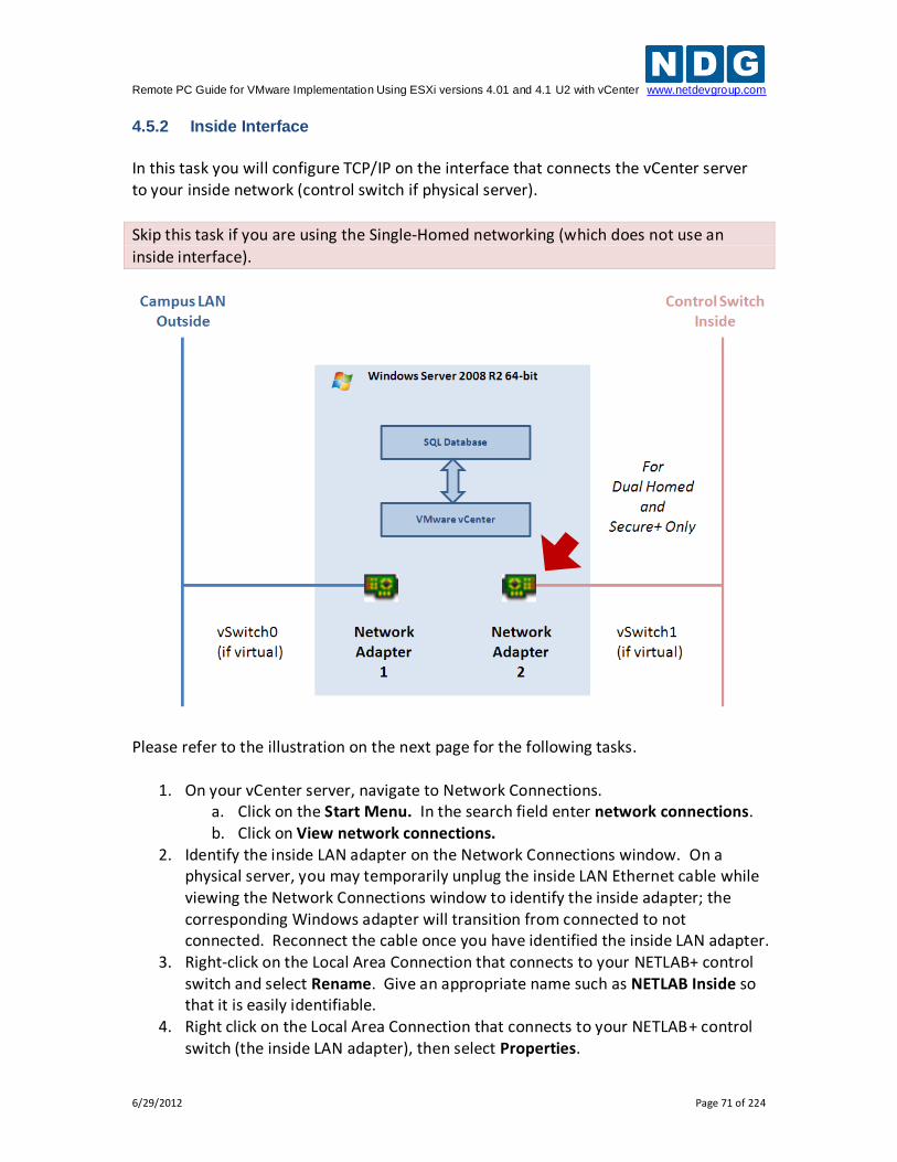
Remote PC Guide for VMware Implementation Using ESXi versions 4.01 and 4.1 U2 with vCenter www.netdevgroup.com
6/29/2012 Page 71 of 224
4.5.2 Inside Interface
In this task you will configure TCP/IP on the interface that connects the vCenter server to your inside network (control switch if physical server).
Skip this task if you are using the Single-Homed networking (which does not use an
inside interface).
Please refer to the illustration on the next page for the following tasks.
1. On your vCenter server, navigate to Network Connections. a. Click on the Start Menu. In the search field enter network connections. b. Click on View network connections.
2. Identify the inside LAN adapter on the Network Connections window. On a physical server, you may temporarily unplug the inside LAN Ethernet cable while viewing the Network Connections window to identify the inside adapter; the corresponding Windows adapter will transition from connected to not connected. Reconnect the cable once you have identified the inside LAN adapter.
3. Right-click on the Local Area Connection that connects to your NETLAB+ control switch and select Rename. Give an appropriate name such as NETLAB Inside so that it is easily identifiable.
4. Right click on the Local Area Connection that connects to your NETLAB+ control switch (the inside LAN adapter), then select Properties.
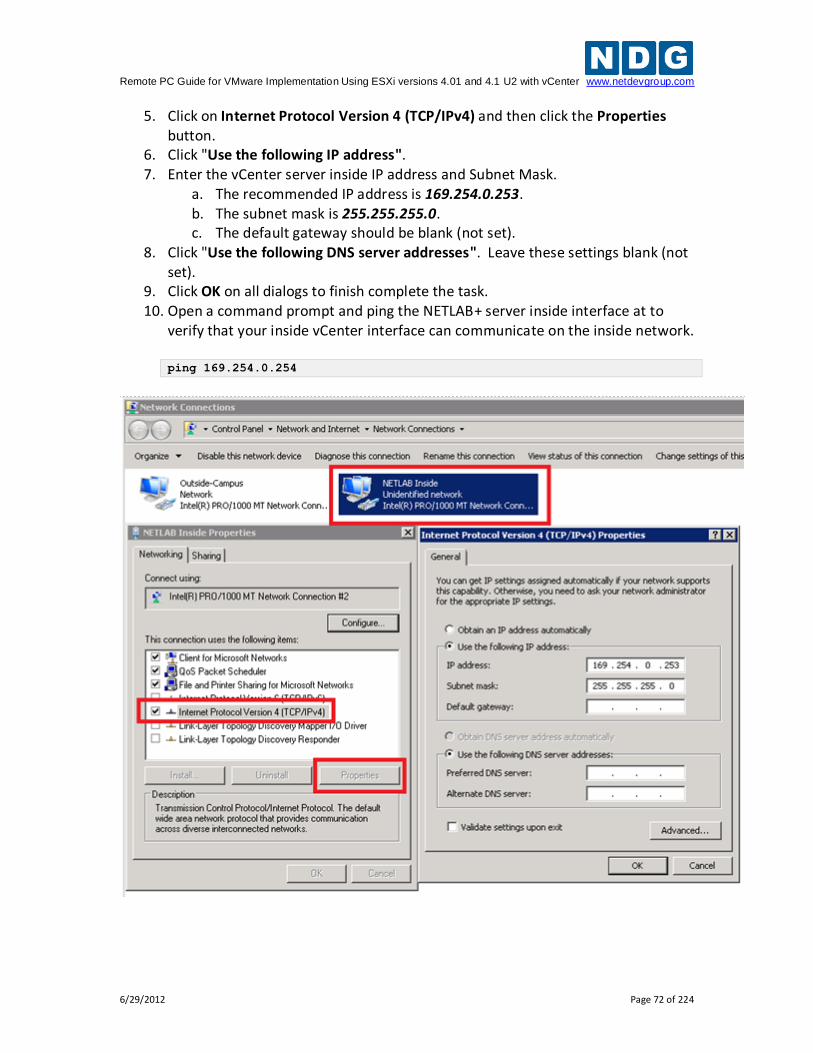
Remote PC Guide for VMware Implementation Using ESXi versions 4.01 and 4.1 U2 with vCenter www.netdevgroup.com
6/29/2012 Page 72 of 224
5. Click on Internet Protocol Version 4 (TCP/IPv4) and then click the Properties button.
6. Click "Use the following IP address". 7. Enter the vCenter server inside IP address and Subnet Mask.
a. The recommended IP address is 169.254.0.253. b. The subnet mask is 255.255.255.0. c. The default gateway should be blank (not set).
8. Click "Use the following DNS server addresses". Leave these settings blank (not set).
9. Click OK on all dialogs to finish complete the task. 10. Open a command prompt and ping the NETLAB+ server inside interface at to
verify that your inside vCenter interface can communicate on the inside network. ping 169.254.0.254
Remote PC Guide for VMware Implementation Using ESXi versions 4.01 and 4.1 U2 with vCenter www.netdevgroup.com
6/29/2012 Page 73 of 224
4.6 Installing VMware vCenter and Related Software
vCenter Server requires Windows Server 2008 R2 64-bit. Please install this on your virtual machine or physical machine depending on your setup. Make sure all operating system updates are applied before continuing. If you install vCenter Server on a virtual
machine, be sure to install VMware Tools before continuing.
4.6.1 Installing vCenter with Microsoft SQL Server 2008 R2 (Option 1 and 3)
This section is recommended for vCenter deployments that will exceed 50 virtual machines. If you are not exceeding 50 virtual machines, but plan to in the near future, it is recommended that you use this section.
This setup is the same for both virtual vCenter (Option 1) and bare metal vCenter (Option 3) installs. Please have your license key for Microsoft SQL Server 2008 R2 available. Microsoft SQL Server 2008 R2 must be installed and a database created before installing vCenter Server. This section will assist you in that setup.
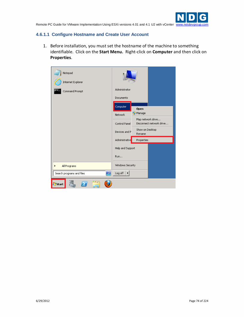
Remote PC Guide for VMware Implementation Using ESXi versions 4.01 and 4.1 U2 with vCenter www.netdevgroup.com
6/29/2012 Page 74 of 224
4.6.1.1 Configure Hostname and Create User Account
1. Before installation, you must set the hostname of the machine to something
identifiable. Click on the Start Menu. Right-click on Computer and then click on Properties.
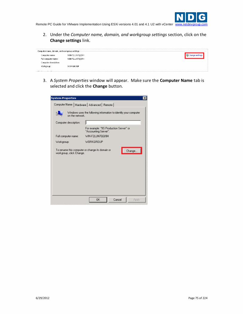
Remote PC Guide for VMware Implementation Using ESXi versions 4.01 and 4.1 U2 with vCenter www.netdevgroup.com
6/29/2012 Page 75 of 224
2. Under the Computer name, domain, and workgroup settings section, click on the Change settings link.
3. A System Properties window will appear. Make sure the Computer Name tab is selected and click the Change button.
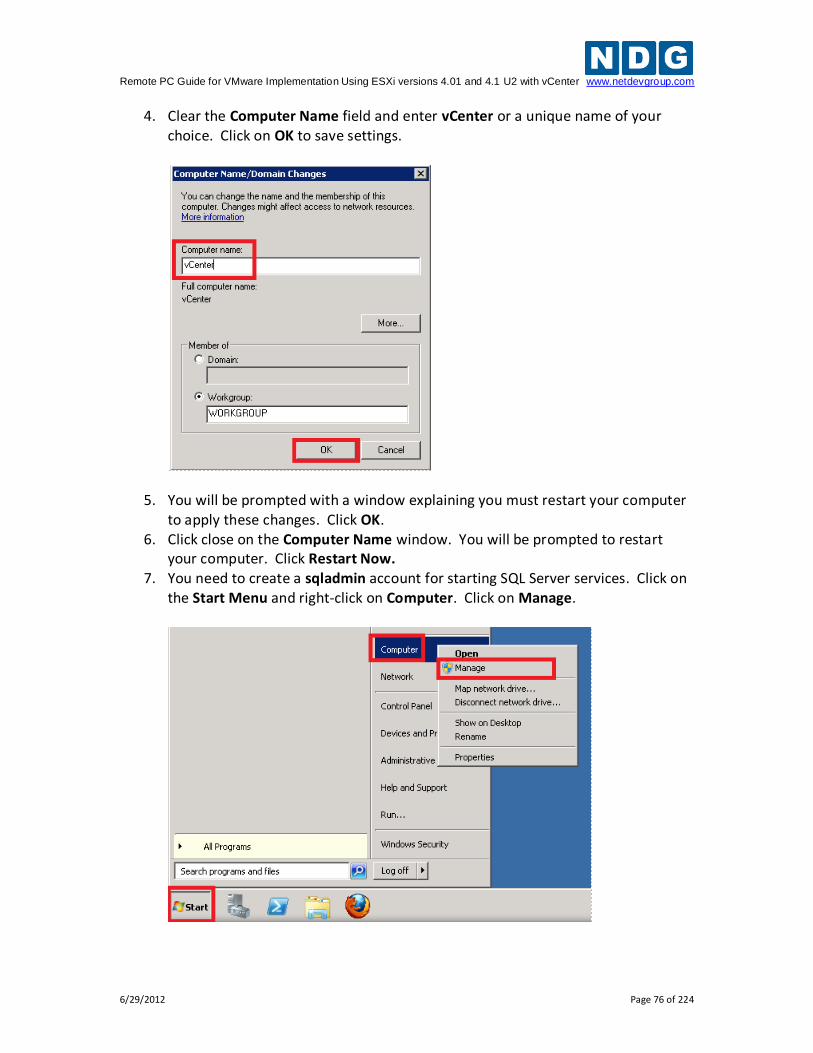
Remote PC Guide for VMware Implementation Using ESXi versions 4.01 and 4.1 U2 with vCenter www.netdevgroup.com
6/29/2012 Page 76 of 224
4. Clear the Computer Name field and enter vCenter or a unique name of your choice. Click on OK to save settings.
5. You will be prompted with a window explaining you must restart your computer to apply these changes. Click OK.
6. Click close on the Computer Name window. You will be prompted to restart your computer. Click Restart Now.
7. You need to create a sqladmin account for starting SQL Server services. Click on the Start Menu and right-click on Computer. Click on Manage.
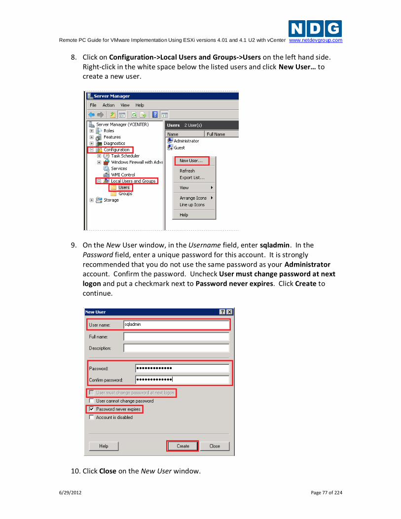
Remote PC Guide for VMware Implementation Using ESXi versions 4.01 and 4.1 U2 with vCenter www.netdevgroup.com
6/29/2012 Page 77 of 224
8. Click on Configuration->Local Users and Groups->Users on the left hand side. Right-click in the white space below the listed users and click New User… to create a new user.
9. On the New User window, in the Username field, enter sqladmin. In the Password field, enter a unique password for this account. It is strongly recommended that you do not use the same password as your Administrator account. Confirm the password. Uncheck User must change password at next logon and put a checkmark next to Password never expires. Click Create to continue.
10. Click Close on the New User window.
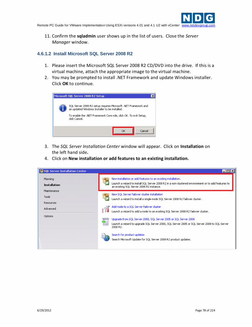
Remote PC Guide for VMware Implementation Using ESXi versions 4.01 and 4.1 U2 with vCenter www.netdevgroup.com
6/29/2012 Page 78 of 224
11. Confirm the sqladmin user shows up in the list of users. Close the Server Manager window.
4.6.1.2 Install Microsoft SQL Server 2008 R2
1. Please insert the Microsoft SQL Server 2008 R2 CD/DVD into the drive. If this is a
virtual machine, attach the appropriate image to the virtual machine. 2. You may be prompted to install .NET Framework and update Windows installer.
Click OK to continue.
3. The SQL Server Installation Center window will appear. Click on Installation on the left hand side.
4. Click on New installation or add features to an existing installation.
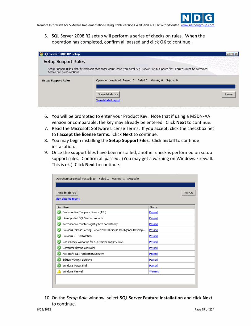
Remote PC Guide for VMware Implementation Using ESXi versions 4.01 and 4.1 U2 with vCenter www.netdevgroup.com
6/29/2012 Page 79 of 224
5. SQL Server 2008 R2 setup will perform a series of checks on rules. When the operation has completed, confirm all passed and click OK to continue.
6. You will be prompted to enter your Product Key. Note that if using a MSDN-AA version or comparable, the key may already be entered. Click Next to continue.
7. Read the Microsoft Software License Terms. If you accept, click the checkbox net to I accept the license terms. Click Next to continue.
8. You may begin installing the Setup Support Files. Click Install to continue installation.
9. Once the support files have been installed, another check is performed on setup support rules. Confirm all passed. (You may get a warning on Windows Firewall. This is ok.) Click Next to continue.
10. On the Setup Role window, select SQL Server Feature Installation and click Next to continue.
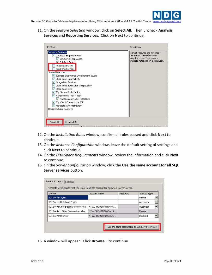
Remote PC Guide for VMware Implementation Using ESXi versions 4.01 and 4.1 U2 with vCenter www.netdevgroup.com
6/29/2012 Page 80 of 224
11. On the Feature Selection window, click on Select All. Then uncheck Analysis Services and Reporting Services. Click on Next to continue.
12. On the Installation Rules window, confirm all rules passed and click Next to continue.
13. On the Instance Configuration window, leave the default setting of settings and click Next to continue.
14. On the Disk Space Requirements window, review the information and click Next to continue.
15. On the Server Configuration window, click the Use the same account for all SQL Server services button.
16. A window will appear. Click Browse… to continue.
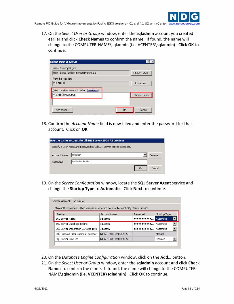
Remote PC Guide for VMware Implementation Using ESXi versions 4.01 and 4.1 U2 with vCenter www.netdevgroup.com
6/29/2012 Page 81 of 224
17. On the Select User or Group window, enter the sqladmin account you created earlier and click Check Names to confirm the name. If found, the name will change to the COMPUTER-NAME\sqladmin (i.e. VCENTER\sqladmin). Click OK to continue.
18. Confirm the Account Name field is now filled and enter the password for that account. Click on OK.
19. On the Server Configuration window, locate the SQL Server Agent service and change the Startup Type to Automatic. Click Next to continue.
20. On the Database Engine Configuration window, click on the Add… button. 21. On the Select User or Group window, enter the sqladmin account and click Check
Names to confirm the name. If found, the name will change to the COMPUTER-NAME\sqladmin (i.e. VCENTER\sqladmin). Click OK to continue.
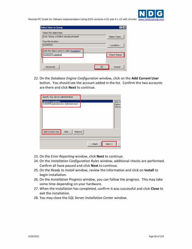
Remote PC Guide for VMware Implementation Using ESXi versions 4.01 and 4.1 U2 with vCenter www.netdevgroup.com
6/29/2012 Page 82 of 224
22. On the Database Engine Configuration window, click on the Add Current User button. You should see the account added in the list. Confirm the two accounts are there and click Next to continue.
23. On the Error Reporting window, click Next to continue. 24. On the Installation Configuration Rules window, additional checks are performed.
Confirm all have passed and click Next to continue. 25. On the Ready to Install window, review the information and click on Install to
begin installation. 26. On the Installation Progress window, you can follow the progress. This may take
some time depending on your hardware. 27. When the installation has completed, confirm it was successful and click Close to
exit the installation. 28. You may close the SQL Server Installation Center window.
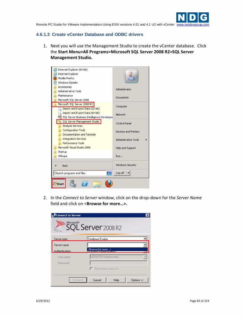
Remote PC Guide for VMware Implementation Using ESXi versions 4.01 and 4.1 U2 with vCenter www.netdevgroup.com
6/29/2012 Page 83 of 224
4.6.1.3 Create vCenter Database and ODBC drivers
1. Next you will use the Management Studio to create the vCenter database. Click
the Start Menu>All Programs>Microsoft SQL Server 2008 R2>SQL Server Management Studio.
2. In the Connect to Server window, click on the drop-down for the Server Name field and click on <Browse for more…>.
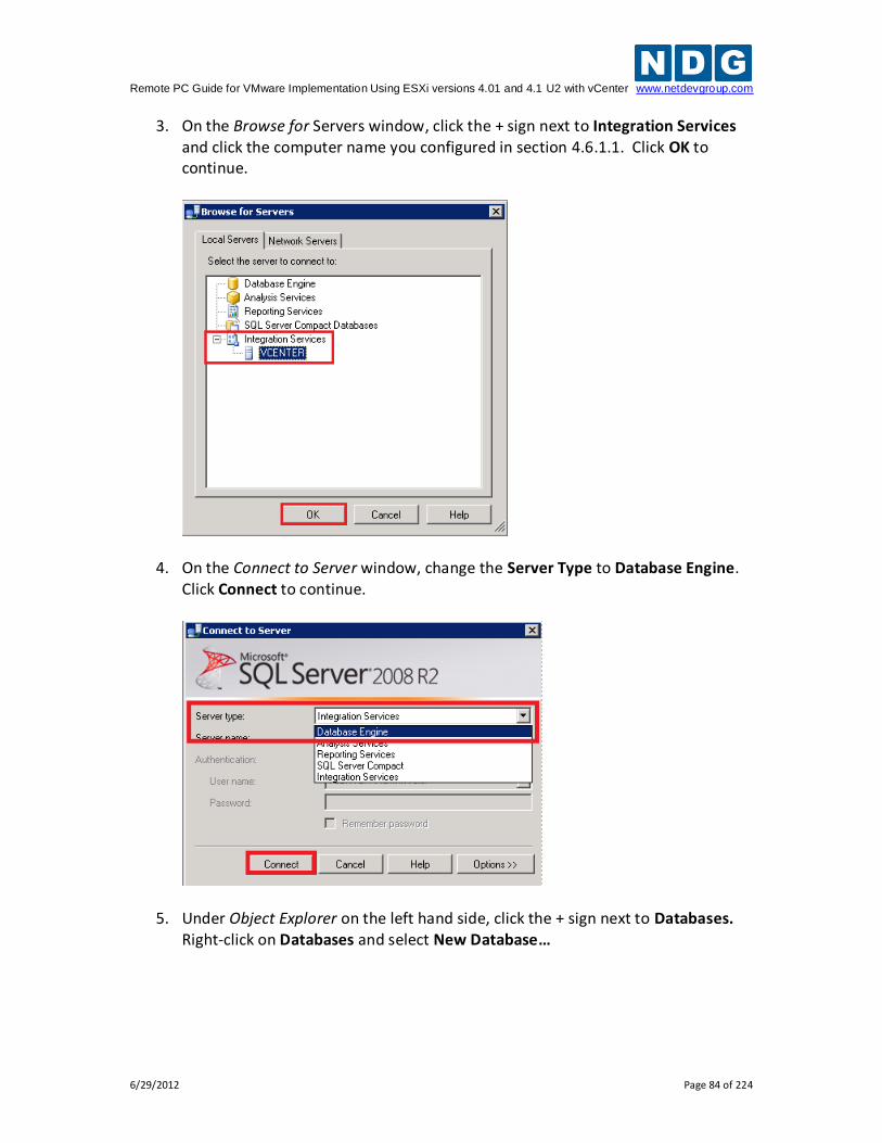
Remote PC Guide for VMware Implementation Using ESXi versions 4.01 and 4.1 U2 with vCenter www.netdevgroup.com
6/29/2012 Page 84 of 224
3. On the Browse for Servers window, click the + sign next to Integration Services and click the computer name you configured in section 4.6.1.1. Click OK to continue.
4. On the Connect to Server window, change the Server Type to Database Engine. Click Connect to continue.
5. Under Object Explorer on the left hand side, click the + sign next to Databases. Right-click on Databases and select New Database…
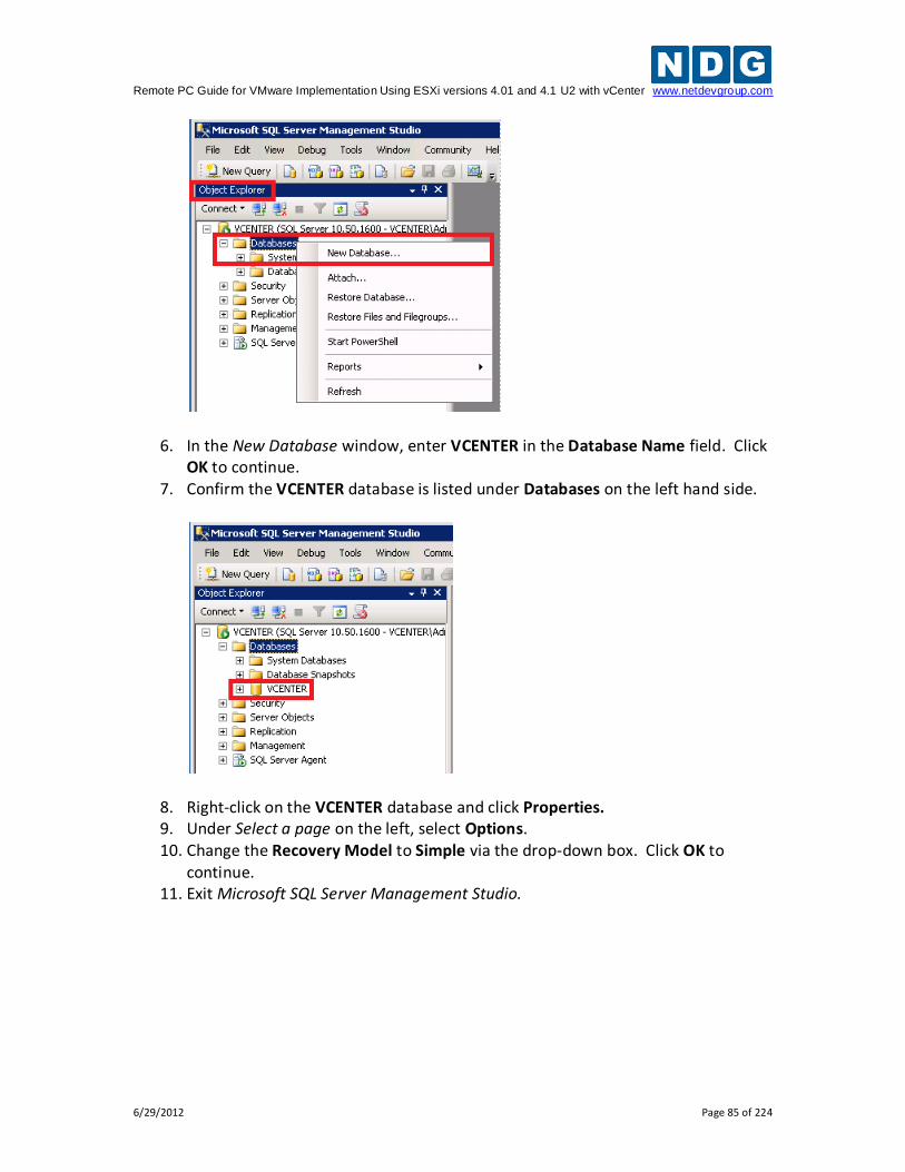
Remote PC Guide for VMware Implementation Using ESXi versions 4.01 and 4.1 U2 with vCenter www.netdevgroup.com
6/29/2012 Page 85 of 224
6. In the New Database window, enter VCENTER in the Database Name field. Click OK to continue.
7. Confirm the VCENTER database is listed under Databases on the left hand side.
8. Right-click on the VCENTER database and click Properties. 9. Under Select a page on the left, select Options. 10. Change the Recovery Model to Simple via the drop-down box. Click OK to
continue. 11. Exit Microsoft SQL Server Management Studio.
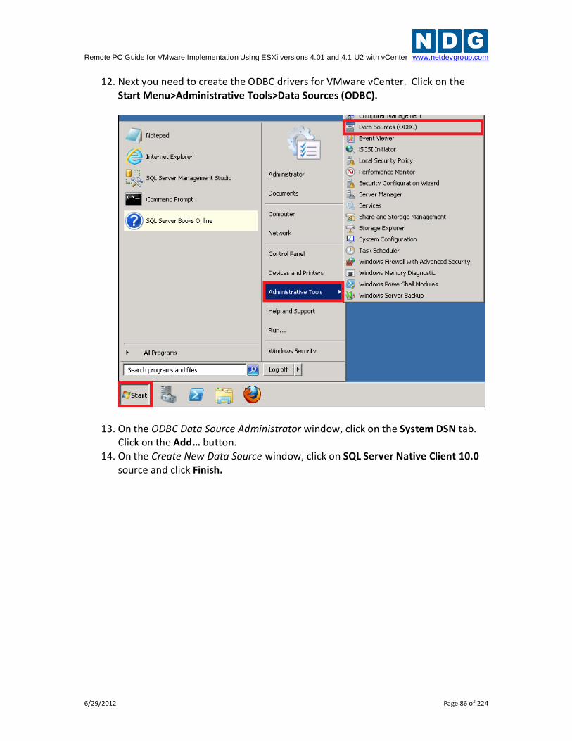
Remote PC Guide for VMware Implementation Using ESXi versions 4.01 and 4.1 U2 with vCenter www.netdevgroup.com
6/29/2012 Page 86 of 224
12. Next you need to create the ODBC drivers for VMware vCenter. Click on the Start Menu>Administrative Tools>Data Sources (ODBC).
13. On the ODBC Data Source Administrator window, click on the System DSN tab. Click on the Add… button.
14. On the Create New Data Source window, click on SQL Server Native Client 10.0 source and click Finish.
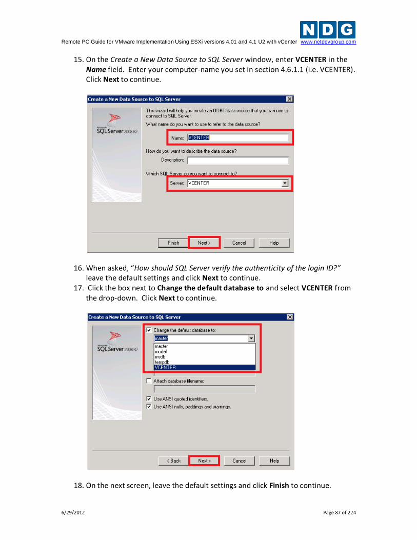
Remote PC Guide for VMware Implementation Using ESXi versions 4.01 and 4.1 U2 with vCenter www.netdevgroup.com
6/29/2012 Page 87 of 224
15. On the Create a New Data Source to SQL Server window, enter VCENTER in the Name field. Enter your computer-name you set in section 4.6.1.1 (i.e. VCENTER). Click Next to continue.
16. When asked, “How should SQL Server verify the authenticity of the login ID?” leave the default settings and click Next to continue.
17. Click the box next to Change the default database to and select VCENTER from the drop-down. Click Next to continue.
18. On the next screen, leave the default settings and click Finish to continue.
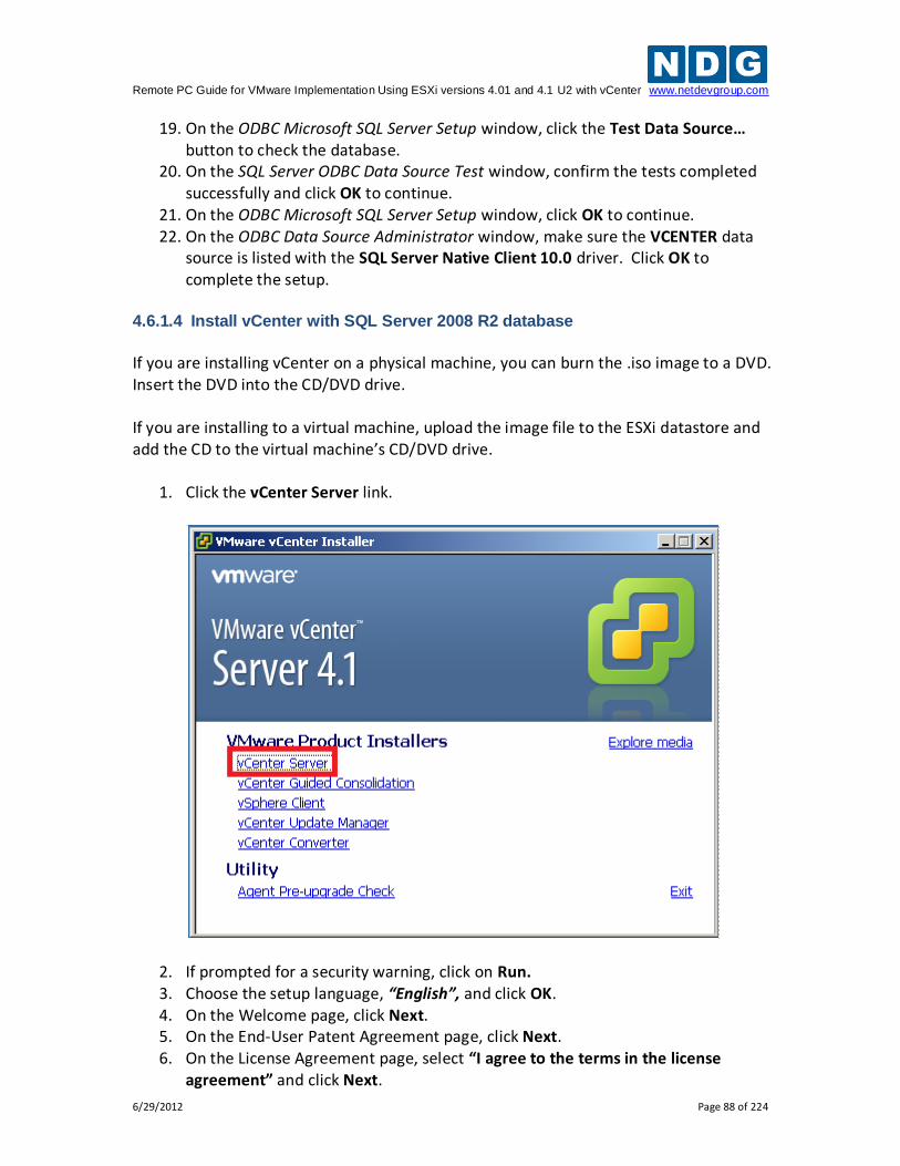
Remote PC Guide for VMware Implementation Using ESXi versions 4.01 and 4.1 U2 with vCenter www.netdevgroup.com
6/29/2012 Page 88 of 224
19. On the ODBC Microsoft SQL Server Setup window, click the Test Data Source… button to check the database.
20. On the SQL Server ODBC Data Source Test window, confirm the tests completed successfully and click OK to continue.
21. On the ODBC Microsoft SQL Server Setup window, click OK to continue. 22. On the ODBC Data Source Administrator window, make sure the VCENTER data
source is listed with the SQL Server Native Client 10.0 driver. Click OK to complete the setup.
4.6.1.4 Install vCenter with SQL Server 2008 R2 database
If you are installing vCenter on a physical machine, you can burn the .iso image to a DVD. Insert the DVD into the CD/DVD drive. If you are installing to a virtual machine, upload the image file to the ESXi datastore and add the CD to the virtual machine’s CD/DVD drive.
1. Click the vCenter Server link.
2. If prompted for a security warning, click on Run. 3. Choose the setup language, “English”, and click OK. 4. On the Welcome page, click Next. 5. On the End-User Patent Agreement page, click Next. 6. On the License Agreement page, select “I agree to the terms in the license
agreement” and click Next.
Remote PC Guide for VMware Implementation Using ESXi versions 4.01 and 4.1 U2 with vCenter www.netdevgroup.com
6/29/2012 Page 89 of 224
7. On the Customer Information page, enter your information. In the License key field, enter the license key assigned to you when you downloaded vCenter Server from the VMware e-academy website and then click Next.
8. On the Database Options page, select Use an existing support database and select VCENTER (MS SQL) from the Data source Name (DSN) drop-down box. Click Next to continue.
9. Confirm the correct DSN and ODBC Driver are selected and click Next to continue. 10. On the vCenter Server Service page, enter the account password and confirm the
password. Click Next to continue. 11. On the Destination Folder page, leave the default and click Next. 12. On the vCenter Linked Mode Options page, leave “Create a standalone VMware
vCenter Server instance” selected and click Next. 13. On the Configure Ports page, leave the defaults and click Next. 14. On the vCenter Server JVM Memory page, select “Small (less than 100 hosts)”
and click Next. 15. On the Ready to Install the Program page, click Install. The installation will take
a few minutes to complete. 16. When the installation is complete, click Finish to exit the wizard. Leave the
VMware vCenter Installer window open.
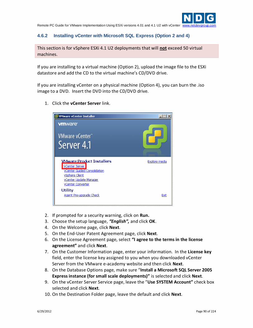
Remote PC Guide for VMware Implementation Using ESXi versions 4.01 and 4.1 U2 with vCenter www.netdevgroup.com
6/29/2012 Page 90 of 224
4.6.2 Installing vCenter with Microsoft SQL Express (Option 2 and 4)
This section is for vSphere ESXi 4.1 U2 deployments that will not exceed 50 virtual
machines.
If you are installing to a virtual machine (Option 2), upload the image file to the ESXi datastore and add the CD to the virtual machine’s CD/DVD drive. If you are installing vCenter on a physical machine (Option 4), you can burn the .iso image to a DVD. Insert the DVD into the CD/DVD drive.
1. Click the vCenter Server link.
2. If prompted for a security warning, click on Run. 3. Choose the setup language, “English”, and click OK. 4. On the Welcome page, click Next. 5. On the End-User Patent Agreement page, click Next. 6. On the License Agreement page, select “I agree to the terms in the license
agreement” and click Next. 7. On the Customer Information page, enter your information. In the License key
field, enter the license key assigned to you when you downloaded vCenter Server from the VMware e-academy website and then click Next.
8. On the Database Options page, make sure “Install a Microsoft SQL Server 2005 Express instance (for small scale deployments)” is selected and click Next.
9. On the vCenter Server Service page, leave the “Use SYSTEM Account” check box selected and click Next.
10. On the Destination Folder page, leave the default and click Next.
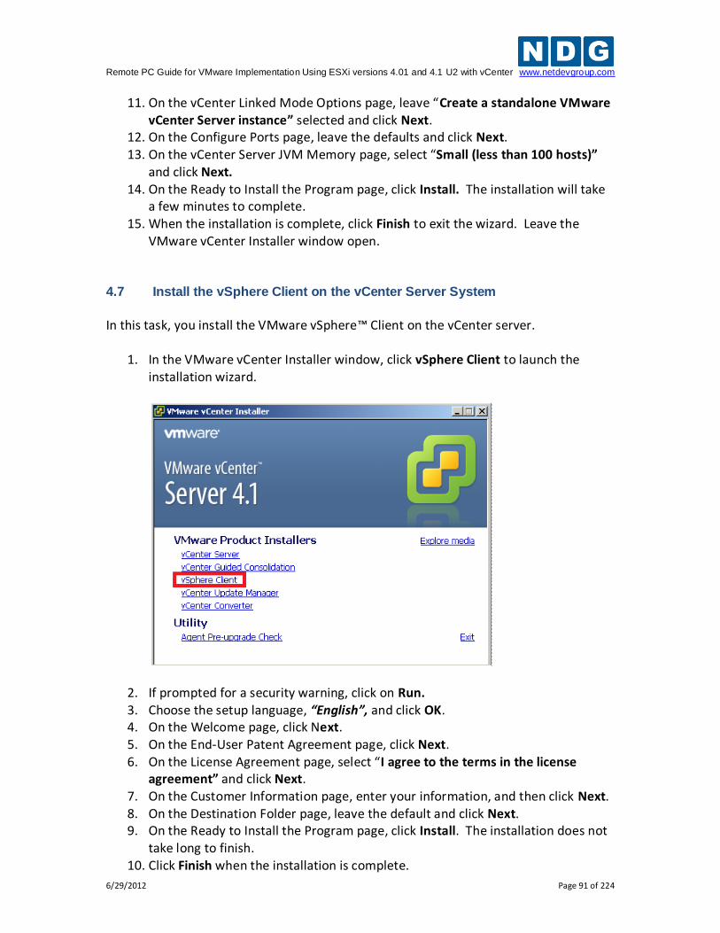
Remote PC Guide for VMware Implementation Using ESXi versions 4.01 and 4.1 U2 with vCenter www.netdevgroup.com
6/29/2012 Page 91 of 224
11. On the vCenter Linked Mode Options page, leave “Create a standalone VMware vCenter Server instance” selected and click Next.
12. On the Configure Ports page, leave the defaults and click Next. 13. On the vCenter Server JVM Memory page, select “Small (less than 100 hosts)”
and click Next. 14. On the Ready to Install the Program page, click Install. The installation will take
a few minutes to complete. 15. When the installation is complete, click Finish to exit the wizard. Leave the
VMware vCenter Installer window open. 4.7 Install the vSphere Client on the vCenter Server System
In this task, you install the VMware vSphere™ Client on the vCenter server.
1. In the VMware vCenter Installer window, click vSphere Client to launch the installation wizard.
2. If prompted for a security warning, click on Run. 3. Choose the setup language, “English”, and click OK. 4. On the Welcome page, click Next. 5. On the End-User Patent Agreement page, click Next. 6. On the License Agreement page, select “I agree to the terms in the license
agreement” and click Next. 7. On the Customer Information page, enter your information, and then click Next. 8. On the Destination Folder page, leave the default and click Next. 9. On the Ready to Install the Program page, click Install. The installation does not
take long to finish. 10. Click Finish when the installation is complete.
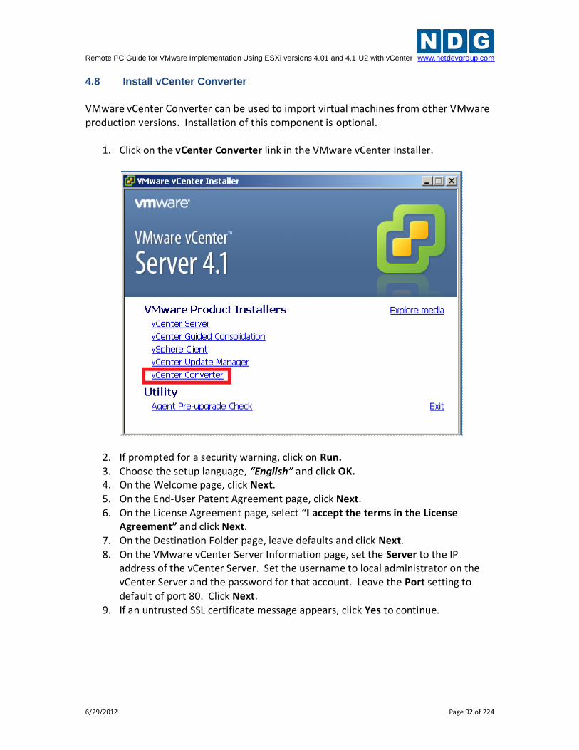
Remote PC Guide for VMware Implementation Using ESXi versions 4.01 and 4.1 U2 with vCenter www.netdevgroup.com
6/29/2012 Page 92 of 224
4.8 Install vCenter Converter
VMware vCenter Converter can be used to import virtual machines from other VMware production versions. Installation of this component is optional.
1. Click on the vCenter Converter link in the VMware vCenter Installer.
2. If prompted for a security warning, click on Run. 3. Choose the setup language, “English” and click OK. 4. On the Welcome page, click Next. 5. On the End-User Patent Agreement page, click Next. 6. On the License Agreement page, select “I accept the terms in the License
Agreement” and click Next. 7. On the Destination Folder page, leave defaults and click Next. 8. On the VMware vCenter Server Information page, set the Server to the IP
address of the vCenter Server. Set the username to local administrator on the vCenter Server and the password for that account. Leave the Port setting to default of port 80. Click Next.
9. If an untrusted SSL certificate message appears, click Yes to continue.
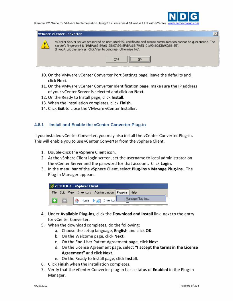
Remote PC Guide for VMware Implementation Using ESXi versions 4.01 and 4.1 U2 with vCenter www.netdevgroup.com
6/29/2012 Page 93 of 224
10. On the VMware vCenter Converter Port Settings page, leave the defaults and click Next.
11. On the VMware vCenter Converter Identification page, make sure the IP address of your vCenter Server is selected and click on Next.
12. On the Ready to Install page, click Install. 13. When the installation completes, click Finish. 14. Click Exit to close the VMware vCenter Installer.
4.8.1 Install and Enable the vCenter Converter Plug-in
If you installed vCenter Converter, you may also install the vCenter Converter Plug-in. This will enable you to use vCenter Converter from the vSphere Client.
1. Double-click the vSphere Client icon. 2. At the vSphere Client login screen, set the username to local administrator on
the vCenter Server and the password for that account. Click Login. 3. In the menu bar of the vSphere Client, select Plug-ins > Manage Plug-ins. The
Plug-in Manager appears.
4. Under Available Plug-ins, click the Download and Install link, next to the entry for vCenter Converter.
5. When the download completes, do the following: a. Choose the setup language, English and click OK. b. On the Welcome page, click Next. c. On the End-User Patent Agreement page, click Next. d. On the License Agreement page, select “I accept the terms in the License
Agreement” and click Next. e. On the Ready to Install page, click Install.
6. Click Finish when the installation completes. 7. Verify that the vCenter Converter plug-in has a status of Enabled in the Plug-in
Manager.
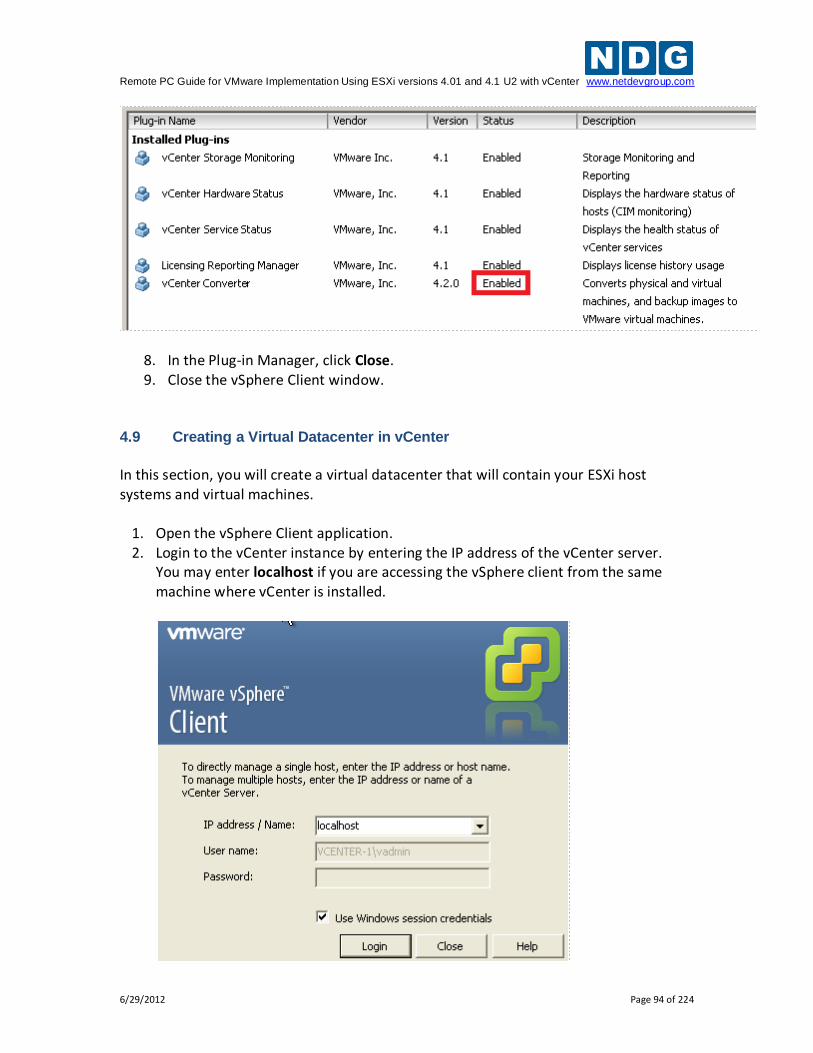
Remote PC Guide for VMware Implementation Using ESXi versions 4.01 and 4.1 U2 with vCenter www.netdevgroup.com
6/29/2012 Page 94 of 224
8. In the Plug-in Manager, click Close. 9. Close the vSphere Client window.
4.9 Creating a Virtual Datacenter in vCenter
In this section, you will create a virtual datacenter that will contain your ESXi host systems and virtual machines.
1. Open the vSphere Client application. 2. Login to the vCenter instance by entering the IP address of the vCenter server.
You may enter localhost if you are accessing the vSphere client from the same machine where vCenter is installed.
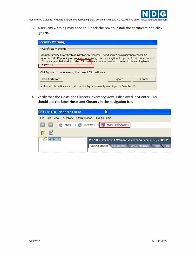
Remote PC Guide for VMware Implementation Using ESXi versions 4.01 and 4.1 U2 with vCenter www.netdevgroup.com
6/29/2012 Page 95 of 224
3. A security warning may appear. Check the box to install the certificate and click Ignore.
4. Verify that the Hosts and Clusters Inventory view is displayed in vCenter. You should see the label Hosts and Clusters in the navigation bar.
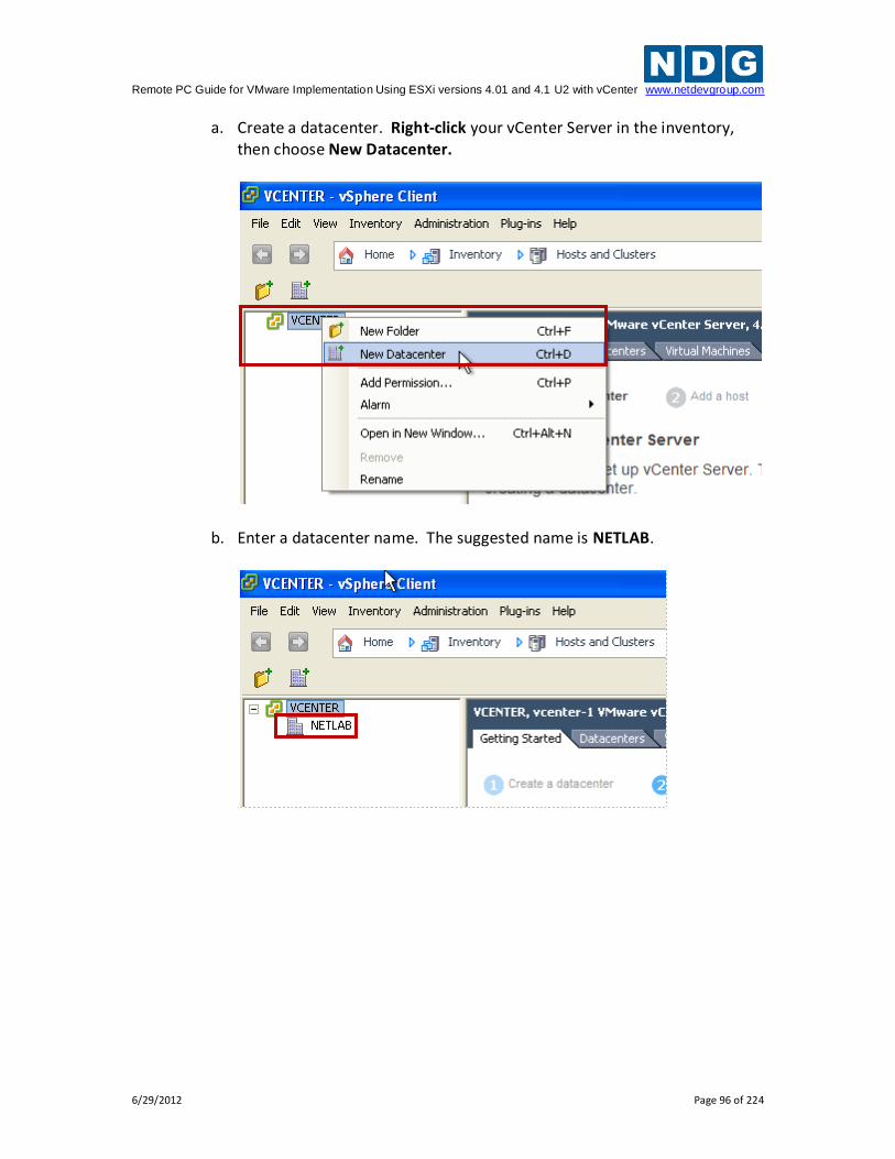
Remote PC Guide for VMware Implementation Using ESXi versions 4.01 and 4.1 U2 with vCenter www.netdevgroup.com
6/29/2012 Page 96 of 224
a. Create a datacenter. Right-click your vCenter Server in the inventory, then choose New Datacenter.
b. Enter a datacenter name. The suggested name is NETLAB.
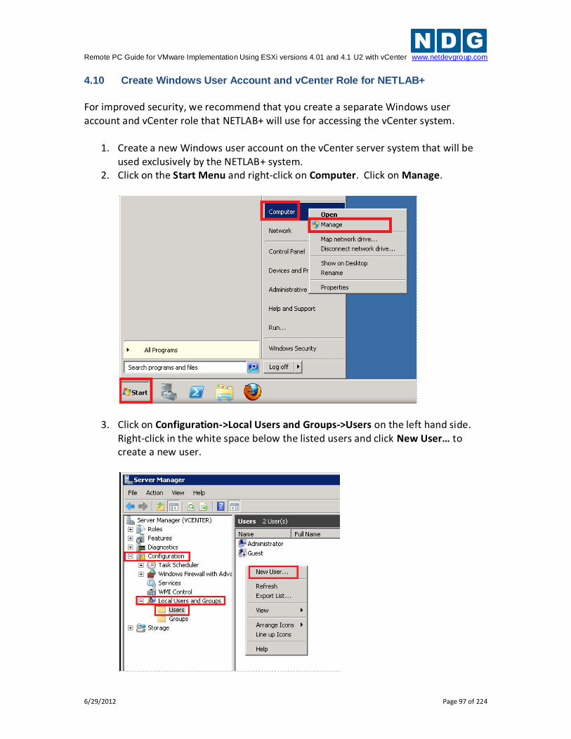
Remote PC Guide for VMware Implementation Using ESXi versions 4.01 and 4.1 U2 with vCenter www.netdevgroup.com
6/29/2012 Page 97 of 224
4.10 Create Windows User Account and vCenter Role for NETLAB+
For improved security, we recommend that you create a separate Windows user account and vCenter role that NETLAB+ will use for accessing the vCenter system.
1. Create a new Windows user account on the vCenter server system that will be used exclusively by the NETLAB+ system.
2. Click on the Start Menu and right-click on Computer. Click on Manage.
3. Click on Configuration->Local Users and Groups->Users on the left hand side. Right-click in the white space below the listed users and click New User… to create a new user.
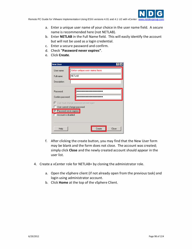
Remote PC Guide for VMware Implementation Using ESXi versions 4.01 and 4.1 U2 with vCenter www.netdevgroup.com
6/29/2012 Page 98 of 224
a. Enter a unique user name of your choice in the user name field. A secure name is recommended here (not NETLAB).
b. Enter NETLAB in the Full Name field. This will easily identify the account but will not be used as a login credential.
c. Enter a secure password and confirm. d. Check "Password never expires". e. Click Create.
f. After clicking the create button, you may find that the New User form may be blank and the form does not close. The account was created; simply click Close and the newly created account should appear in the user list.
4. Create a vCenter role for NETLAB+ by cloning the administrator role.
a. Open the vSphere client (if not already open from the previous task) and
login using administrator account. b. Click Home at the top of the vSphere Client.
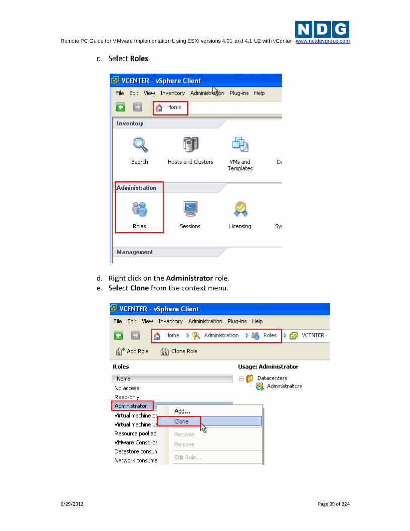
Remote PC Guide for VMware Implementation Using ESXi versions 4.01 and 4.1 U2 with vCenter www.netdevgroup.com
6/29/2012 Page 99 of 224
c. Select Roles.
d. Right click on the Administrator role. e. Select Clone from the context menu.
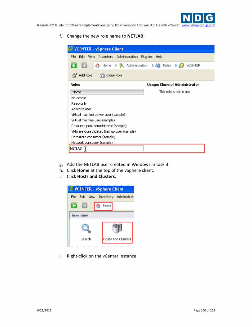
Remote PC Guide for VMware Implementation Using ESXi versions 4.01 and 4.1 U2 with vCenter www.netdevgroup.com
6/29/2012 Page 100 of 224
f. Change the new role name to NETLAB.
g. Add the NETLAB user created in Windows in task 3. h. Click Home at the top of the vSphere client. i. Click Hosts and Clusters.
j. Right-click on the vCenter instance.
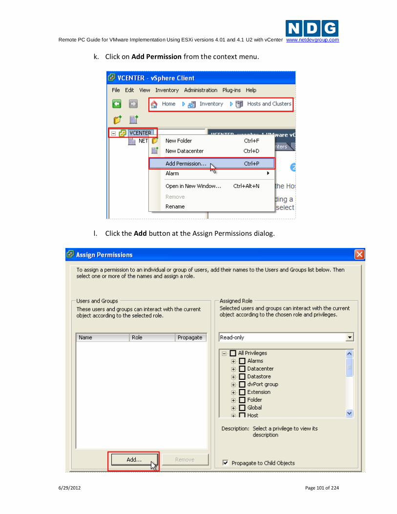
Remote PC Guide for VMware Implementation Using ESXi versions 4.01 and 4.1 U2 with vCenter www.netdevgroup.com
6/29/2012 Page 101 of 224
k. Click on Add Permission from the context menu.
l. Click the Add button at the Assign Permissions dialog.
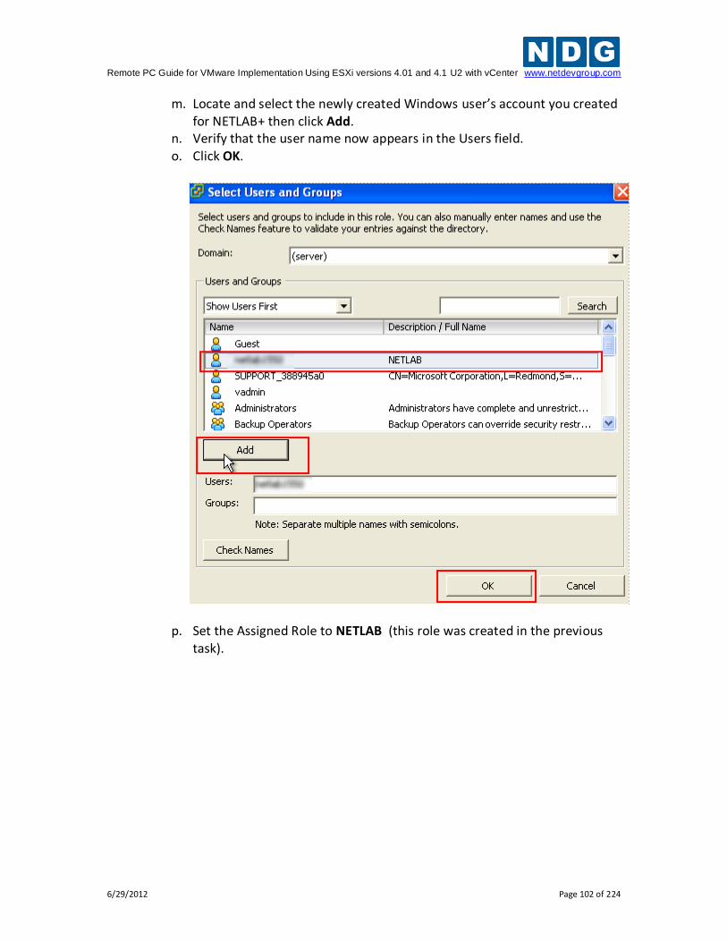
Remote PC Guide for VMware Implementation Using ESXi versions 4.01 and 4.1 U2 with vCenter www.netdevgroup.com
6/29/2012 Page 102 of 224
m. Locate and select the newly created Windows user’s account you created for NETLAB+ then click Add.
n. Verify that the user name now appears in the Users field. o. Click OK.
p. Set the Assigned Role to NETLAB (this role was created in the previous task).
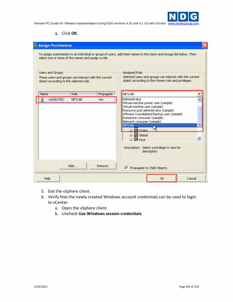
Remote PC Guide for VMware Implementation Using ESXi versions 4.01 and 4.1 U2 with vCenter www.netdevgroup.com
6/29/2012 Page 103 of 224
q. Click OK.
5. Exit the vSphere client. 6. Verify that the newly created Windows account credentials can be used to login
to vCenter. a. Open the vSphere client. b. Uncheck Use Windows session credentials.
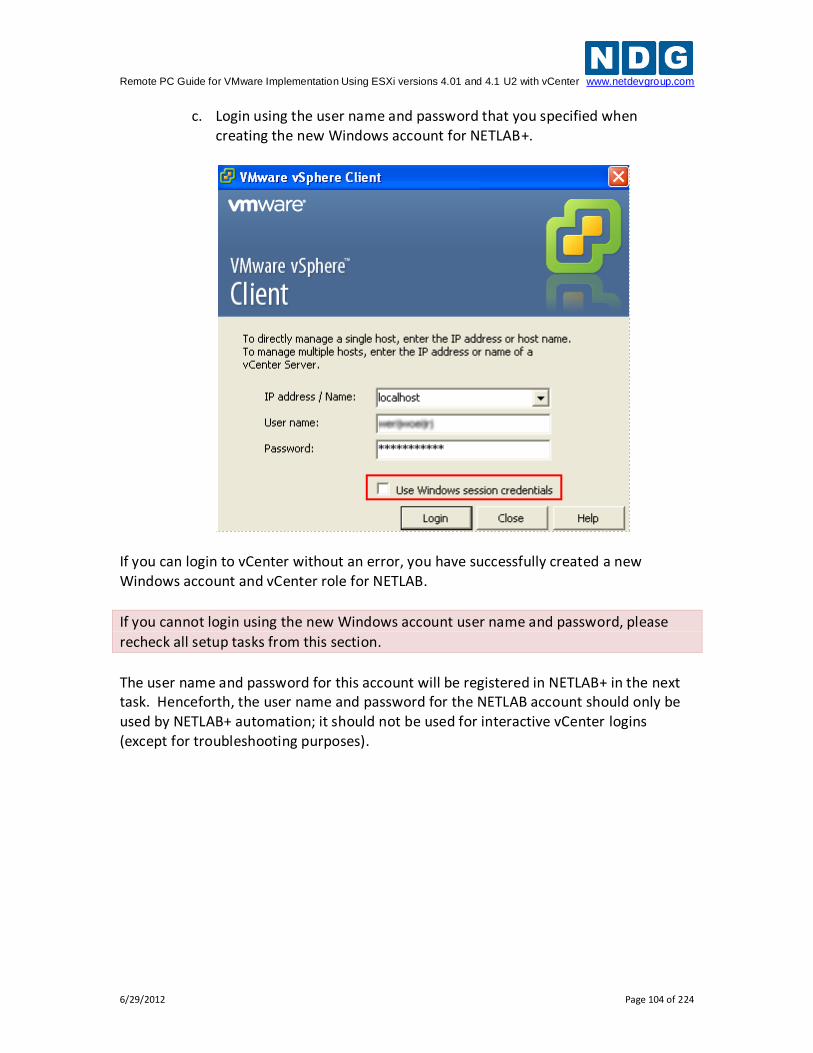
Remote PC Guide for VMware Implementation Using ESXi versions 4.01 and 4.1 U2 with vCenter www.netdevgroup.com
6/29/2012 Page 104 of 224
c. Login using the user name and password that you specified when creating the new Windows account for NETLAB+.
If you can login to vCenter without an error, you have successfully created a new Windows account and vCenter role for NETLAB.
If you cannot login using the new Windows account user name and password, please
recheck all setup tasks from this section.
The user name and password for this account will be registered in NETLAB+ in the next task. Henceforth, the user name and password for the NETLAB account should only be used by NETLAB+ automation; it should not be used for interactive vCenter logins (except for troubleshooting purposes).
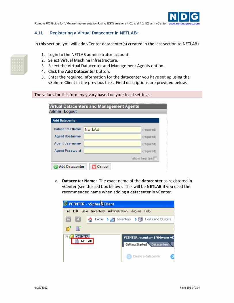
Remote PC Guide for VMware Implementation Using ESXi versions 4.01 and 4.1 U2 with vCenter www.netdevgroup.com
6/29/2012 Page 105 of 224
4.11 Registering a Virtual Datacenter in NETLAB+
In this section, you will add vCenter datacenter(s) created in the last section to NETLAB+.
1. Login to the NETLAB administrator account. 2. Select Virtual Machine Infrastructure. 3. Select the Virtual Datacenter and Management Agents option. 4. Click the Add Datacenter button. 5. Enter the required information for the datacenter you have set up using the
vSphere Client in the previous task. Field descriptions are provided below.
The values for this form may vary based on your local settings.
a. Datacenter Name: The exact name of the datacenter as registered in vCenter (see the red box below). This will be NETLAB if you used the recommended name when adding a datacenter in vCenter.
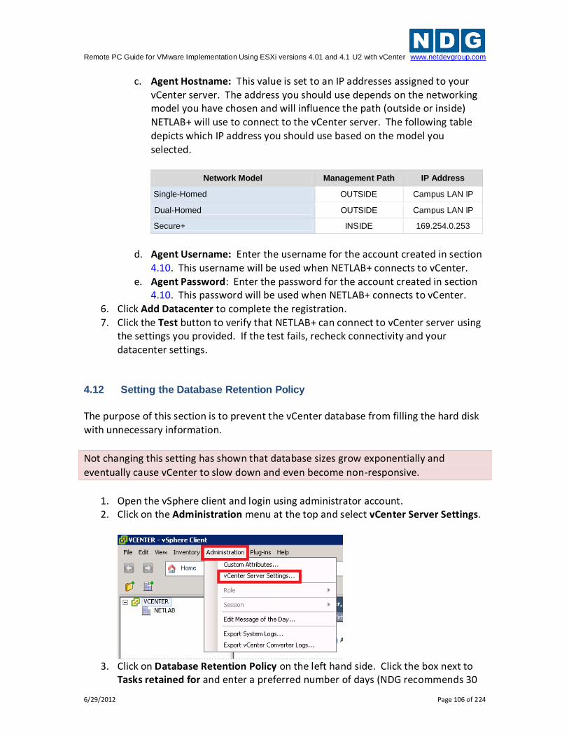
Remote PC Guide for VMware Implementation Using ESXi versions 4.01 and 4.1 U2 with vCenter www.netdevgroup.com
6/29/2012 Page 106 of 224
c. Agent Hostname: This value is set to an IP addresses assigned to your vCenter server. The address you should use depends on the networking model you have chosen and will influence the path (outside or inside) NETLAB+ will use to connect to the vCenter server. The following table depicts which IP address you should use based on the model you selected.
Network Model Management Path IP Address
Single-Homed OUTSIDE Campus LAN IP
Dual-Homed OUTSIDE Campus LAN IP
Secure+ INSIDE 169.254.0.253
d. Agent Username: Enter the username for the account created in section
4.10. This username will be used when NETLAB+ connects to vCenter. e. Agent Password: Enter the password for the account created in section
4.10. This password will be used when NETLAB+ connects to vCenter. 6. Click Add Datacenter to complete the registration. 7. Click the Test button to verify that NETLAB+ can connect to vCenter server using
the settings you provided. If the test fails, recheck connectivity and your datacenter settings.
4.12 Setting the Database Retention Policy
The purpose of this section is to prevent the vCenter database from filling the hard disk with unnecessary information.
Not changing this setting has shown that database sizes grow exponentially and
eventually cause vCenter to slow down and even become non-responsive.
1. Open the vSphere client and login using administrator account. 2. Click on the Administration menu at the top and select vCenter Server Settings.
3. Click on Database Retention Policy on the left hand side. Click the box next to
Tasks retained for and enter a preferred number of days (NDG recommends 30
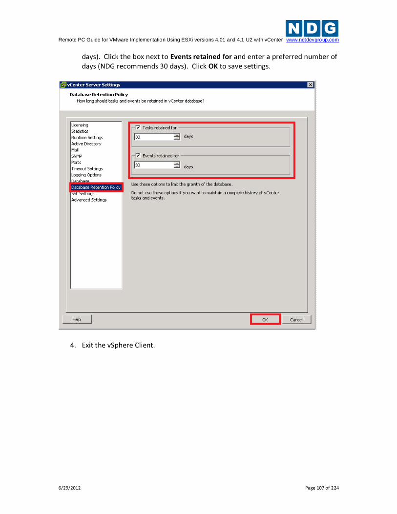
Remote PC Guide for VMware Implementation Using ESXi versions 4.01 and 4.1 U2 with vCenter www.netdevgroup.com
6/29/2012 Page 107 of 224
days). Click the box next to Events retained for and enter a preferred number of days (NDG recommends 30 days). Click OK to save settings.
4. Exit the vSphere Client.
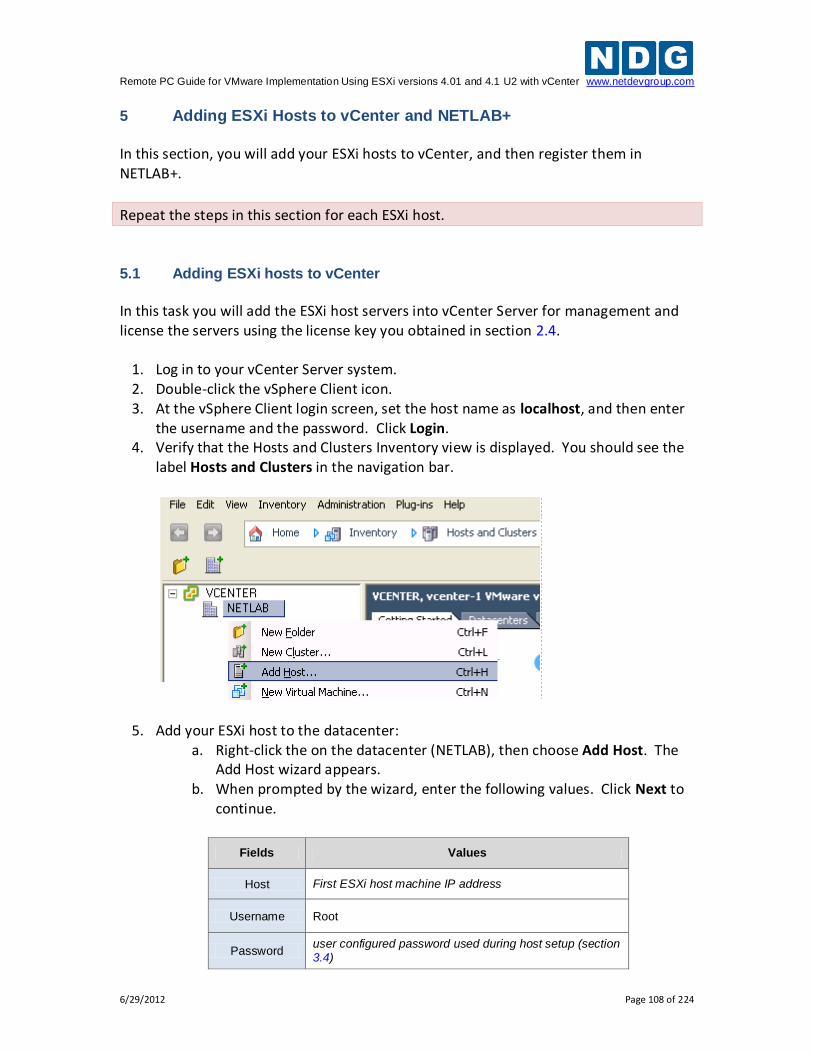
Remote PC Guide for VMware Implementation Using ESXi versions 4.01 and 4.1 U2 with vCenter www.netdevgroup.com
6/29/2012 Page 108 of 224
5 Adding ESXi Hosts to vCenter and NETLAB+ In this section, you will add your ESXi hosts to vCenter, and then register them in NETLAB+.
Repeat the steps in this section for each ESXi host.
5.1 Adding ESXi hosts to vCenter
In this task you will add the ESXi host servers into vCenter Server for management and license the servers using the license key you obtained in section 2.4.
1. Log in to your vCenter Server system. 2. Double-click the vSphere Client icon. 3. At the vSphere Client login screen, set the host name as localhost, and then enter
the username and the password. Click Login. 4. Verify that the Hosts and Clusters Inventory view is displayed. You should see the
label Hosts and Clusters in the navigation bar.
5. Add your ESXi host to the datacenter: a. Right-click the on the datacenter (NETLAB), then choose Add Host. The
Add Host wizard appears. b. When prompted by the wizard, enter the following values. Click Next to
continue.
Fields Values
Host First ESXi host machine IP address
Username Root
Password user configured password used during host setup (section 3.4)
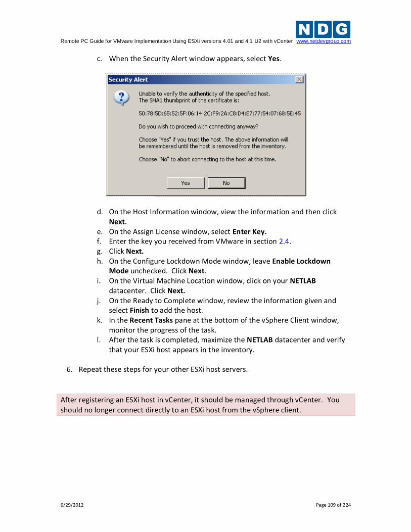
Remote PC Guide for VMware Implementation Using ESXi versions 4.01 and 4.1 U2 with vCenter www.netdevgroup.com
6/29/2012 Page 109 of 224
c. When the Security Alert window appears, select Yes.
d. On the Host Information window, view the information and then click Next.
e. On the Assign License window, select Enter Key. f. Enter the key you received from VMware in section 2.4. g. Click Next. h. On the Configure Lockdown Mode window, leave Enable Lockdown
Mode unchecked. Click Next. i. On the Virtual Machine Location window, click on your NETLAB
datacenter. Click Next. j. On the Ready to Complete window, review the information given and
select Finish to add the host. k. In the Recent Tasks pane at the bottom of the vSphere Client window,
monitor the progress of the task. l. After the task is completed, maximize the NETLAB datacenter and verify
that your ESXi host appears in the inventory.
6. Repeat these steps for your other ESXi host servers.
After registering an ESXi host in vCenter, it should be managed through vCenter. You
should no longer connect directly to an ESXi host from the vSphere client.
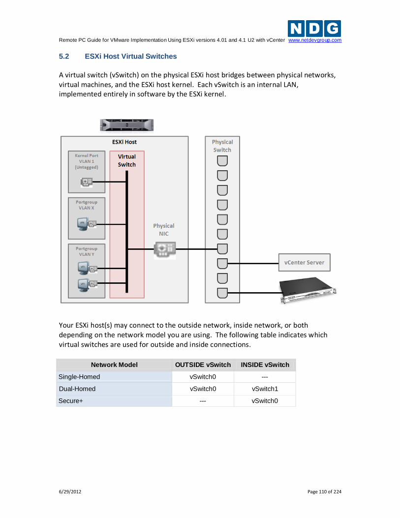
Remote PC Guide for VMware Implementation Using ESXi versions 4.01 and 4.1 U2 with vCenter www.netdevgroup.com
6/29/2012 Page 110 of 224
5.2 ESXi Host Virtual Switches
A virtual switch (vSwitch) on the physical ESXi host bridges between physical networks, virtual machines, and the ESXi host kernel. Each vSwitch is an internal LAN, implemented entirely in software by the ESXi kernel.
Your ESXi host(s) may connect to the outside network, inside network, or both depending on the network model you are using. The following table indicates which virtual switches are used for outside and inside connections.
Network Model OUTSIDE vSwitch INSIDE vSwitch
Single-Homed vSwitch0 ---
Dual-Homed vSwitch0 vSwitch1
Secure+ --- vSwitch0
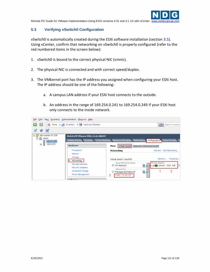
Remote PC Guide for VMware Implementation Using ESXi versions 4.01 and 4.1 U2 with vCenter www.netdevgroup.com
6/29/2012 Page 111 of 224
5.3 Verifying vSwitch0 Configuration
vSwitch0 is automatically created during the ESXi software installation (section 3.5). Using vCenter, confirm that networking on vSwitch0 is properly configured (refer to the red numbered items in the screen below): 1. vSwitch0 is bound to the correct physical NIC (vmnic).
2. The physical NIC is connected and with correct speed/duplex.
3. The VMkernel port has the IP address you assigned when configuring your ESXi host.
The IP address should be one of the following:
a. A campus LAN address if your ESXi host connects to the outside.
b. An address in the range of 169.254.0.241 to 169.254.0.249 if your ESXi host only connects to the inside network.
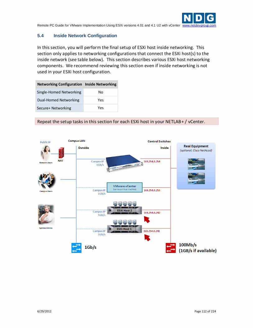
Remote PC Guide for VMware Implementation Using ESXi versions 4.01 and 4.1 U2 with vCenter www.netdevgroup.com
6/29/2012 Page 112 of 224
5.4 Inside Network Configuration
In this section, you will perform the final setup of ESXi host inside networking. This section only applies to networking configurations that connect the ESXi host(s) to the inside network (see table below). This section describes various ESXi host networking components. We recommend reviewing this section even if inside networking is not used in your ESXi host configuration.
Networking Configuration Inside Networking
Single-Homed Networking No
Dual-Homed Networking Yes
Secure+ Networking Yes
Repeat the setup tasks in this section for each ESXi host in your NETLAB+ / vCenter.
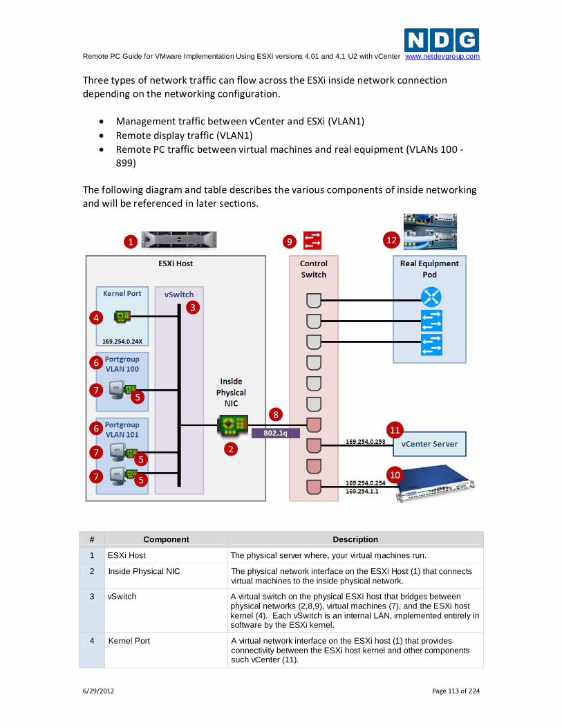
Remote PC Guide for VMware Implementation Using ESXi versions 4.01 and 4.1 U2 with vCenter www.netdevgroup.com
6/29/2012 Page 113 of 224
Three types of network traffic can flow across the ESXi inside network connection depending on the networking configuration.
Management traffic between vCenter and ESXi (VLAN1)
Remote display traffic (VLAN1)
Remote PC traffic between virtual machines and real equipment (VLANs 100 - 899)
The following diagram and table describes the various components of inside networking and will be referenced in later sections.
# Component Description
1 ESXi Host The physical server where, your virtual machines run.
2 Inside Physical NIC The physical network interface on the ESXi Host (1) that connects virtual machines to the inside physical network.
3 vSwitch A virtual switch on the physical ESXi host that bridges between physical networks (2,8,9), virtual machines (7), and the ESXi host kernel (4). Each vSwitch is an internal LAN, implemented entirely in software by the ESXi kernel.
4 Kernel Port A virtual network interface on the ESXi host (1) that provides connectivity between the ESXi host kernel and other components such vCenter (11).
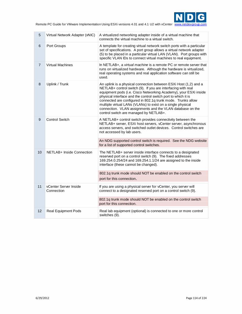
Remote PC Guide for VMware Implementation Using ESXi versions 4.01 and 4.1 U2 with vCenter www.netdevgroup.com
6/29/2012 Page 114 of 224
5 Virtual Network Adapter (vNIC) A virtualized networking adapter inside of a virtual machine that connects the virtual machine to a virtual switch.
6 Port Groups A template for creating virtual network switch ports with a particular set of specifications. A port group allows a virtual network adapter (5) to be placed in a particular virtual LAN (VLAN). Port groups with specific VLAN IDs to connect virtual machines to real equipment.
7 Virtual Machines In NETLAB+, a virtual machine is a remote PC or remote server that
runs on virtualized hardware. Although the hardware is virtualized, real operating systems and real application software can still be used.
8 Uplink / Trunk An uplink is a physical connection between ESXi Host (1,2) and a NETLAB+ control switch (9). If you are interfacing with real equipment pods (i.e. Cisco Networking Academy), your ESXi inside physical interface and the control switch port to which it is connected are configured in 802.1q trunk mode. Trunks allow multiple virtual LANs (VLANs) to exist on a single physical connection. VLAN assignments and the VLAN database on the control switch are managed by NETLAB+.
9 Control Switch A NETLAB+ control switch provides connectivity between the NETLAB+ server, ESXi host servers, vCenter server, asynchronous access servers, and switched outlet devices. Control switches are not accessed by lab users.
An NDG supported control switch is required. See the NDG website
for a list of supported control switches.
10 NETLAB+ Inside Connection The NETLAB+ server inside interface connects to a designated reserved port on a control switch (9). The fixed addresses 169.254.0.254/24 and 169.254.1.1/24 are assigned to the inside interface (these cannot be changed).
802.1q trunk mode should NOT be enabled on the control switch
port for this connection.
11 vCenter Server Inside Connection
If you are using a physical server for vCenter, you server will connect to a designated reserved port on a control switch (9).
802.1q trunk mode should NOT be enabled on the control switch
port for this connection.
12 Real Equipment Pods Real lab equipment (optional) is connected to one or more control switches (9).
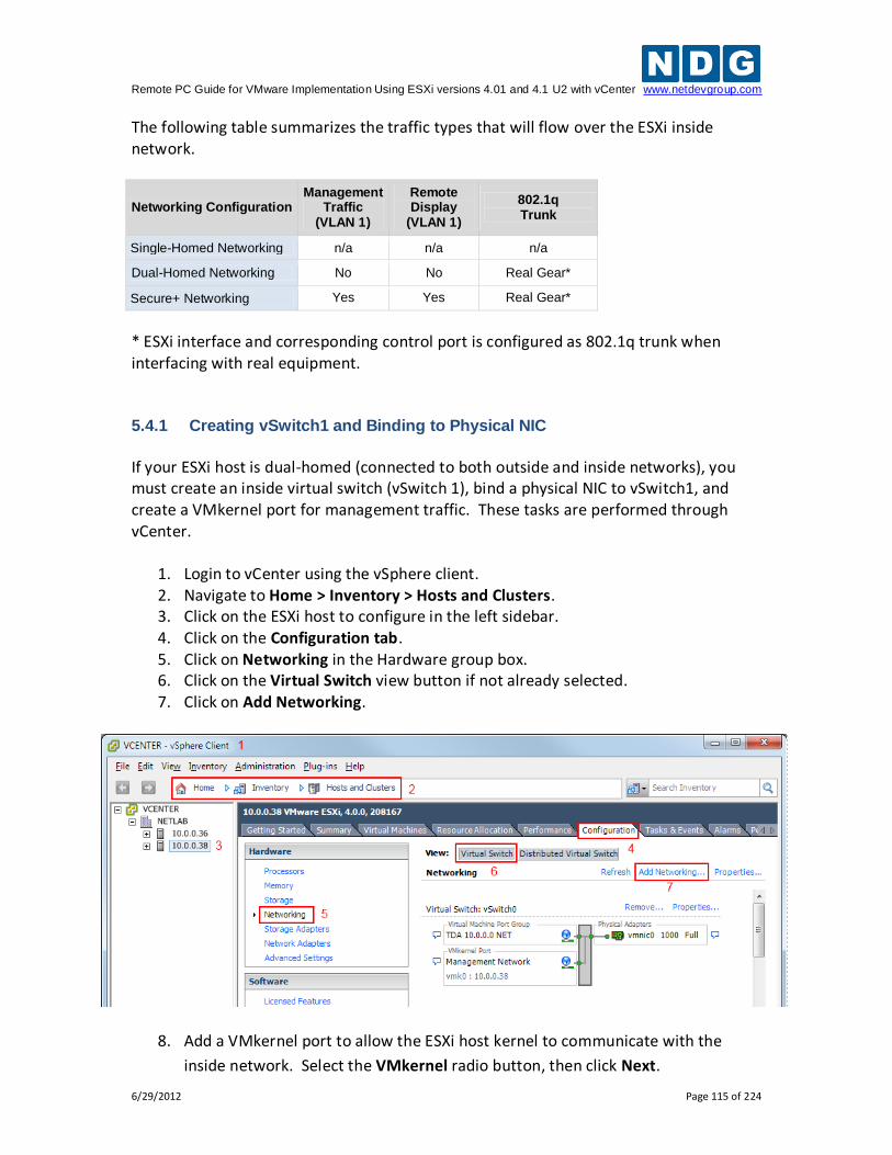
Remote PC Guide for VMware Implementation Using ESXi versions 4.01 and 4.1 U2 with vCenter www.netdevgroup.com
6/29/2012 Page 115 of 224
The following table summarizes the traffic types that will flow over the ESXi inside network.
Networking Configuration Management
Traffic (VLAN 1)
Remote Display
(VLAN 1)
802.1q Trunk
Single-Homed Networking n/a n/a n/a
Dual-Homed Networking No No Real Gear*
Secure+ Networking Yes Yes Real Gear*
* ESXi interface and corresponding control port is configured as 802.1q trunk when interfacing with real equipment. 5.4.1 Creating vSwitch1 and Binding to Physical NIC
If your ESXi host is dual-homed (connected to both outside and inside networks), you must create an inside virtual switch (vSwitch 1), bind a physical NIC to vSwitch1, and create a VMkernel port for management traffic. These tasks are performed through vCenter.
1. Login to vCenter using the vSphere client. 2. Navigate to Home > Inventory > Hosts and Clusters. 3. Click on the ESXi host to configure in the left sidebar. 4. Click on the Configuration tab. 5. Click on Networking in the Hardware group box. 6. Click on the Virtual Switch view button if not already selected. 7. Click on Add Networking.
8. Add a VMkernel port to allow the ESXi host kernel to communicate with the
inside network. Select the VMkernel radio button, then click Next.
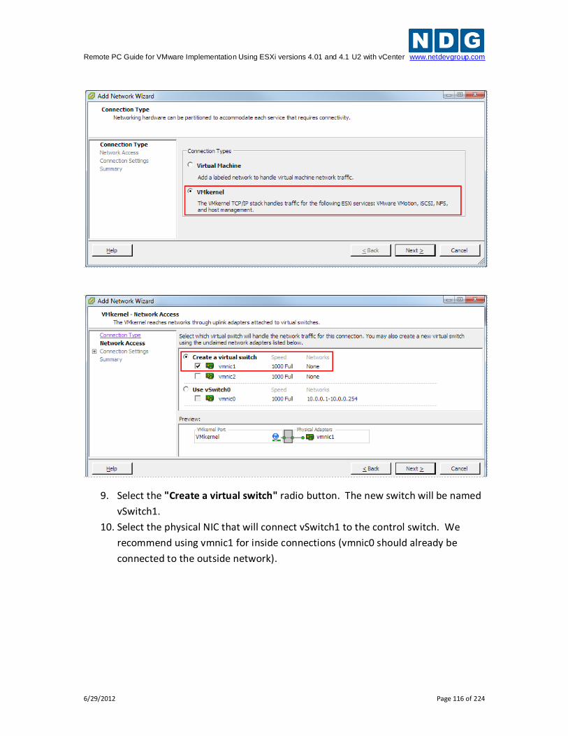
Remote PC Guide for VMware Implementation Using ESXi versions 4.01 and 4.1 U2 with vCenter www.netdevgroup.com
6/29/2012 Page 116 of 224
9. Select the "Create a virtual switch" radio button. The new switch will be named
vSwitch1.
10. Select the physical NIC that will connect vSwitch1 to the control switch. We
recommend using vmnic1 for inside connections (vmnic0 should already be
connected to the outside network).
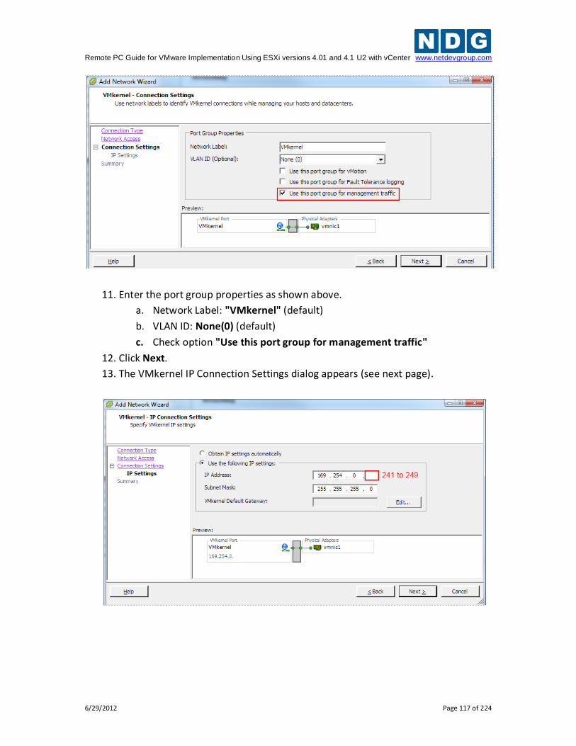
Remote PC Guide for VMware Implementation Using ESXi versions 4.01 and 4.1 U2 with vCenter www.netdevgroup.com
6/29/2012 Page 117 of 224
11. Enter the port group properties as shown above.
a. Network Label: "VMkernel" (default)
b. VLAN ID: None(0) (default)
c. Check option "Use this port group for management traffic"
12. Click Next.
13. The VMkernel IP Connection Settings dialog appears (see next page).
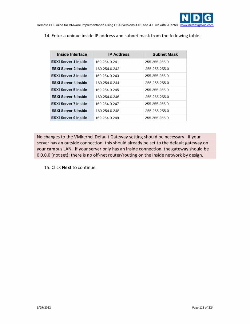
Remote PC Guide for VMware Implementation Using ESXi versions 4.01 and 4.1 U2 with vCenter www.netdevgroup.com
6/29/2012 Page 118 of 224
14. Enter a unique inside IP address and subnet mask from the following table.
Inside Interface IP Address Subnet Mask
ESXi Server 1 Inside 169.254.0.241 255.255.255.0
ESXi Server 2 Inside 169.254.0.242 255.255.255.0
ESXi Server 3 Inside 169.254.0.243 255.255.255.0
ESXi Server 4 Inside 169.254.0.244 255.255.255.0
ESXi Server 5 Inside 169.254.0.245 255.255.255.0
ESXi Server 6 Inside 169.254.0.246 255.255.255.0
ESXi Server 7 Inside 169.254.0.247 255.255.255.0
ESXi Server 8 Inside 169.254.0.248 255.255.255.0
ESXi Server 9 Inside 169.254.0.249 255.255.255.0
No changes to the VMkernel Default Gateway setting should be necessary. If your server has an outside connection, this should already be set to the default gateway on your campus LAN. If your server only has an inside connection, the gateway should be
0.0.0.0 (not set); there is no off-net router/routing on the inside network by design.
15. Click Next to continue.
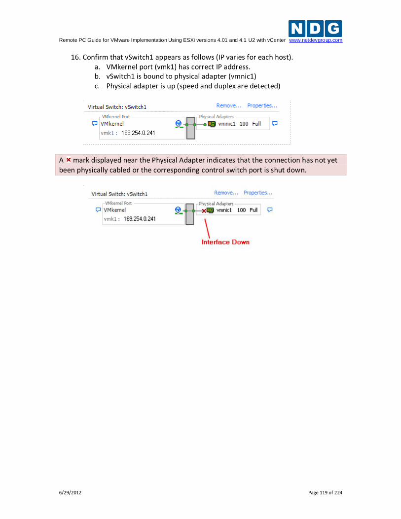
Remote PC Guide for VMware Implementation Using ESXi versions 4.01 and 4.1 U2 with vCenter www.netdevgroup.com
6/29/2012 Page 119 of 224
16. Confirm that vSwitch1 appears as follows (IP varies for each host). a. VMkernel port (vmk1) has correct IP address. b. vSwitch1 is bound to physical adapter (vmnic1) c. Physical adapter is up (speed and duplex are detected)
A mark displayed near the Physical Adapter indicates that the connection has not yet
been physically cabled or the corresponding control switch port is shut down.
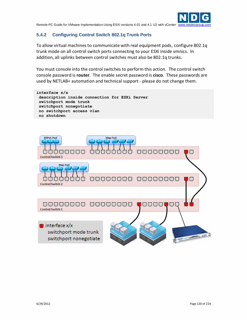
Remote PC Guide for VMware Implementation Using ESXi versions 4.01 and 4.1 U2 with vCenter www.netdevgroup.com
6/29/2012 Page 120 of 224
5.4.2 Configuring Control Switch 802.1q Trunk Ports
To allow virtual machines to communicate with real equipment pods, configure 802.1q trunk mode on all control switch ports connecting to your ESXi inside vmnics. In addition, all uplinks between control switches must also be 802.1q trunks. You must console into the control switches to perform this action. The control switch console password is router. The enable secret password is cisco. These passwords are used by NETLAB+ automation and technical support - please do not change them. interface x/x
description inside connection for ESXi Server
switchport mode trunk
switchport nonegotiate
no switchport access vlan
no shutdown
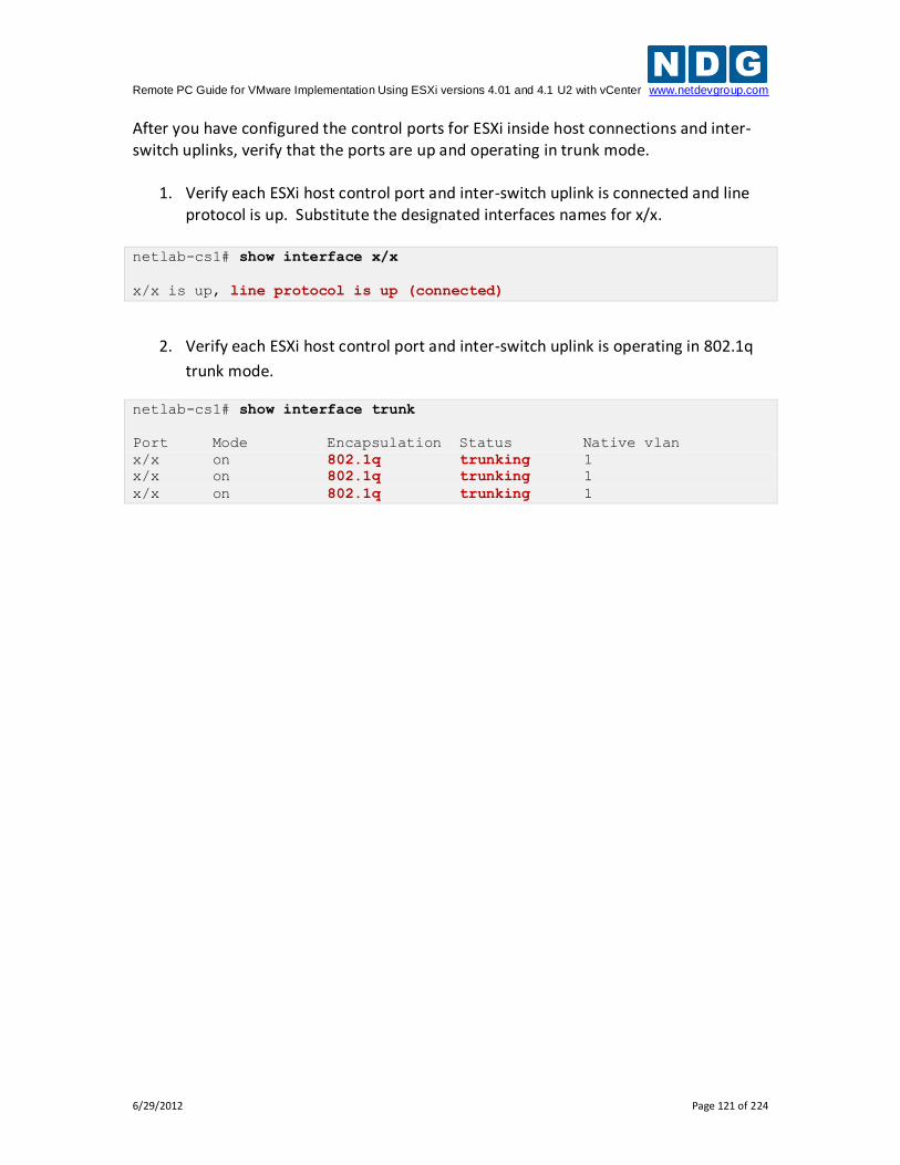
Remote PC Guide for VMware Implementation Using ESXi versions 4.01 and 4.1 U2 with vCenter www.netdevgroup.com
6/29/2012 Page 121 of 224
After you have configured the control ports for ESXi inside host connections and inter-switch uplinks, verify that the ports are up and operating in trunk mode.
1. Verify each ESXi host control port and inter-switch uplink is connected and line protocol is up. Substitute the designated interfaces names for x/x.
netlab-cs1# show interface x/x
x/x is up, line protocol is up (connected)
2. Verify each ESXi host control port and inter-switch uplink is operating in 802.1q
trunk mode.
netlab-cs1# show interface trunk
Port Mode Encapsulation Status Native vlan
x/x on 802.1q trunking 1
x/x on 802.1q trunking 1
x/x on 802.1q trunking 1
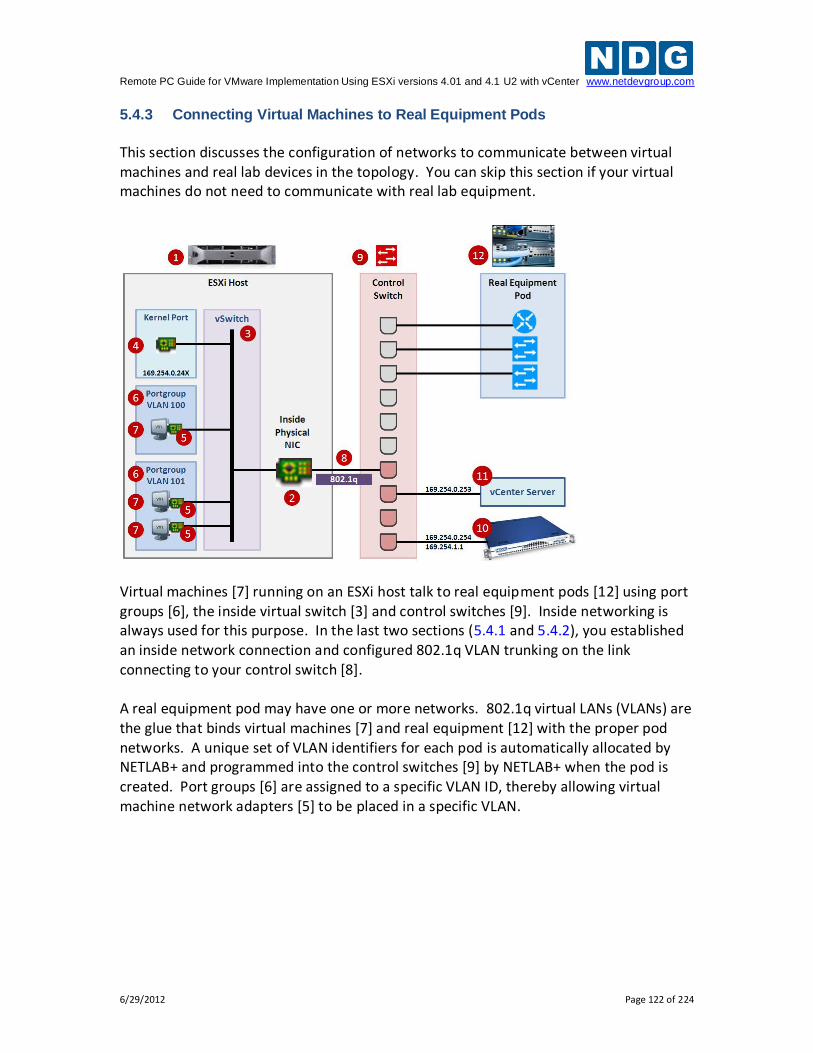
Remote PC Guide for VMware Implementation Using ESXi versions 4.01 and 4.1 U2 with vCenter www.netdevgroup.com
6/29/2012 Page 122 of 224
5.4.3 Connecting Virtual Machines to Real Equipment Pods
This section discusses the configuration of networks to communicate between virtual machines and real lab devices in the topology. You can skip this section if your virtual machines do not need to communicate with real lab equipment.
Virtual machines [7] running on an ESXi host talk to real equipment pods [12] using port groups [6], the inside virtual switch [3] and control switches [9]. Inside networking is always used for this purpose. In the last two sections (5.4.1 and 5.4.2), you established an inside network connection and configured 802.1q VLAN trunking on the link connecting to your control switch [8]. A real equipment pod may have one or more networks. 802.1q virtual LANs (VLANs) are the glue that binds virtual machines [7] and real equipment [12] with the proper pod networks. A unique set of VLAN identifiers for each pod is automatically allocated by NETLAB+ and programmed into the control switches [9] by NETLAB+ when the pod is created. Port groups [6] are assigned to a specific VLAN ID, thereby allowing virtual machine network adapters [5] to be placed in a specific VLAN.
Remote PC Guide for VMware Implementation Using ESXi versions 4.01 and 4.1 U2 with vCenter www.netdevgroup.com
6/29/2012 Page 123 of 224
As of version 2011.R2, NETLAB+ will automatically setup and teardown VLAN based port
groups on the inside vSwitch on NDG standard pods.
Automatic network setup on NDG standard pods occurs when a pod is reserved. Automatic network teardown on NDG standard pods occurs when a reservation completes. These features are enabled by default but can be disabled on a per pod basis. Refer to Appendix A for pods that require manual networking, such as custom pods. 5.4.3.1 Creating a Real Equipment Pod
Creating a real equipment pod in NETLAB+ should be done first. This will automatically generate the required number of VLANs for the selected pod type, and add those VLANs to the control switches. This should be done before ESXi host networking is configured.
1. Login to the NETLAB+ administrator account. 2. Select Equipment Pods. 3. Click the Add a Pod button at the bottom of the page. 4. Select the desired pod type. Only pod types that use both real lab equipment
and remote PCs are relevant to this section. Our examples use the Multi-purpose Academy Pod, which contains 3 routers, 3 switches, and 3 remote PCs.
5. Complete the New Pod Wizard. Please refer to the NETLAB+ Administrator Guide, NDG website pod specific web pages, and NDG pod guides for pod specific installation instructions.
After the pod is created, you will be placed in the Pod Management page. You will notice that all virtual machines are initially ABSENT. You will add virtual machines to the pod later. 5.4.3.2 Determining the Base VLAN and VLAN Pool
This is now an automated task for NDG standard pods as NETLAB+ version 2011.R2. Refer to Appendix A for manual networking setup guidance for custom pods or pods that do not support automatic networking. 5.4.3.3 Creating Port Groups for Pod VLANs on the Inside Network
This is now an automated task for NDG standard pods as NETLAB+ version 2011.R2. Refer to Appendix A for manual networking setup guidance for custom pods or pods that do not support automatic networking.
Remote PC Guide for VMware Implementation Using ESXi versions 4.01 and 4.1 U2 with vCenter www.netdevgroup.com
6/29/2012 Page 124 of 224
5.4.3.4 Increasing the Inside vSwitch Port Count
By default, a vSwitch is provisioned with 56 virtual ports. This means that 56 virtual network adapters can be connected to the virtual switch, regardless of which port group the adapter is connected. For most NETLAB AE setups, this is sufficient for the inside vSwitch. For large NETLAB PE setups or systems with custom real equipment pods, you may need to increase this value to accommodate more virtual machine connections to the inside vSwitch.
This discussion applies to virtual machines that are part of real equipment pods. Pods that contain only virtual machines are usually placed on separate vSwitches that do not
connect to the inside network / real equipment.
To calculate the number of inside vSwitch ports required on a particular ESXi host, add up the number of virtual machines in real equipment pods that are assigned to the host. This is the number of virtual ports required on the inside vSwitch (assuming one connection per VM). If this number exceeds 50, you should select the next highest port count setting (120). In special cases, an even higher setting may be required. Note: 50 is not an error; 6 extra ports were subtracted (from 56) to allow for VMkernel ports and other possible connections. Higher port count settings consume additional host resources, so you should set this value to the lowest possible setting that provides enough ports for every virtual machine connecting to the inside vSwitch.
There is no warning when the number of virtual ports is exceeded and the problem is not obvious. Some of the virtual machines will fail to communicate for no apparent reason. The only clue may be a disconnected network status from the guest operating
system.
The following procedure is used to increase the number of virtual ports on the inside virtual switch. The same procedure can be used on any virtual switch should the need arise.
1. Login to vCenter using the vSphere client. 2. Navigate to Home > Inventory > Hosts and Clusters. 3. Click on the ESXi host where the pod's virtual machines will run. 4. Click on the Configuration tab. 5. Click on Networking in the Hardware group box. 6. Click on the Virtual Switch view button if not already selected. 7. Click Properties on the INSIDE vSwitch. The inside vSwitch is the one that is
connected to the control switch (typically vSwitch0 if single homed, vSwitch1 if dual homed).
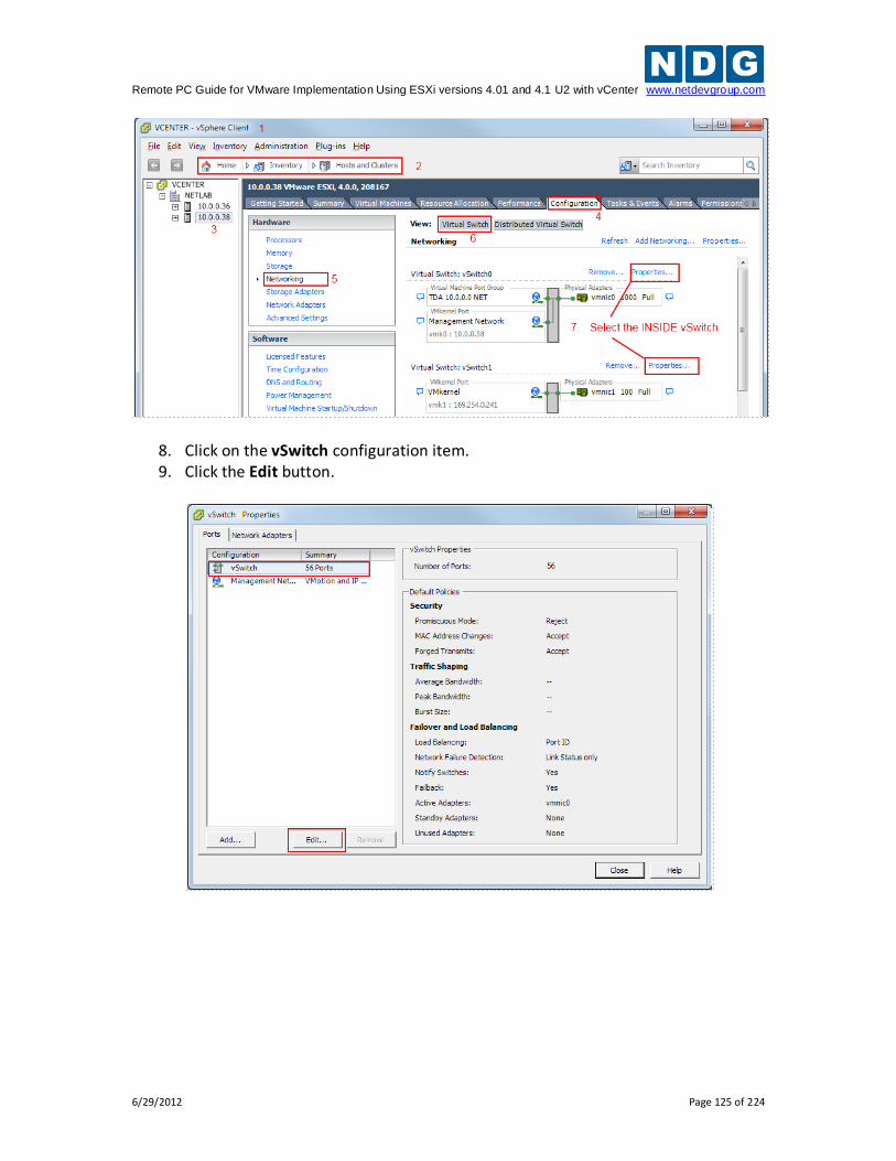
Remote PC Guide for VMware Implementation Using ESXi versions 4.01 and 4.1 U2 with vCenter www.netdevgroup.com
6/29/2012 Page 125 of 224
8. Click on the vSwitch configuration item. 9. Click the Edit button.
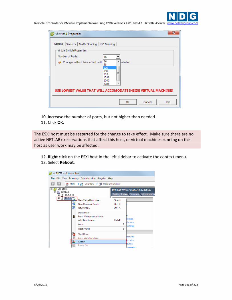
Remote PC Guide for VMware Implementation Using ESXi versions 4.01 and 4.1 U2 with vCenter www.netdevgroup.com
6/29/2012 Page 126 of 224
10. Increase the number of ports, but not higher than needed. 11. Click OK.
The ESXi host must be restarted for the change to take effect. Make sure there are no active NETLAB+ reservations that affect this host, or virtual machines running on this
host as user work may be affected.
12. Right click on the ESXi host in the left sidebar to activate the context menu. 13. Select Reboot.
Remote PC Guide for VMware Implementation Using ESXi versions 4.01 and 4.1 U2 with vCenter www.netdevgroup.com
6/29/2012 Page 127 of 224
5.5 Creating a Safe Staging Network
Most virtual machines in your pods will typically be equipped with one or more virtual network adapters, which are used to communicate with other peer devices in a pod, such as other virtual machines or real networking equipment (Cisco Netacad). Virtual switches and port groups form networks that interconnect virtual machines and real equipment. These networks are created on each ESXi host in one of two ways:
Automatic Networking. Many NETLAB+ virtual pods support automatic networking. When a pod is activated, NETLAB+ will create the necessary virtual switches and port groups, and bind the virtual network adapters automatically.
Manual Networking. For pods that do not support automatic networking, the VMware administrator will create virtual switches and port groups, and bind the virtual network adapters using the vSphere client.
When creating new virtual machines, the vSphere client will require and prompt for an existing network to place the virtual machine. If a network has not been created yet using automatic or manual networking, this creates a dilemma: on what network should I place my virtual machine in the mean time? The default value is usually the network connecting to your campus LAN. This is a potential security risk and should be avoided, unless you want the VM to have temporary access to the campus network or Internet for the purpose of software installation and patches. A safety net is a safe staging network where you can temporarily connect your VMs. It consists of a virtual switch and port group that is not connected to any other networks (virtual or real). Should the virtual machine be powered, its traffic will be confined to the safety net. This ensures that the virtual machine will not pose a security risk to your campus LAN or interfere with other pods, until it is relocated to its final network via automatic or manual networking. To create the safety net on each ESXi host, repeat the following steps:
1. Login to vCenter using the vSphere client. 2. Navigate to Home > Inventory > Hosts and Clusters. 3. Click on the ESXi host to configure in the left sidebar. 4. Click on the Configuration tab. 5. Click on Networking in the Hardware group box. 6. Click on the Virtual Switch view button if not already selected. 7. Click on Add Networking.
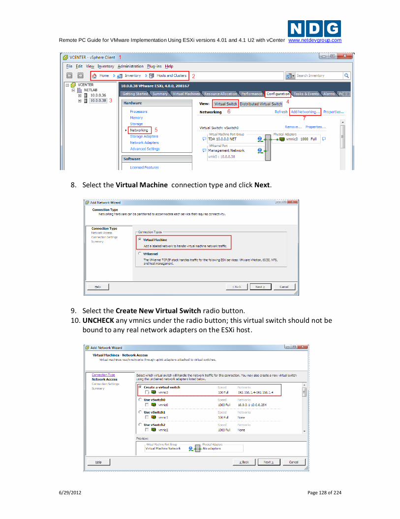
Remote PC Guide for VMware Implementation Using ESXi versions 4.01 and 4.1 U2 with vCenter www.netdevgroup.com
6/29/2012 Page 128 of 224
8. Select the Virtual Machine connection type and click Next.
9. Select the Create New Virtual Switch radio button. 10. UNCHECK any vmnics under the radio button; this virtual switch should not be
bound to any real network adapters on the ESXi host.
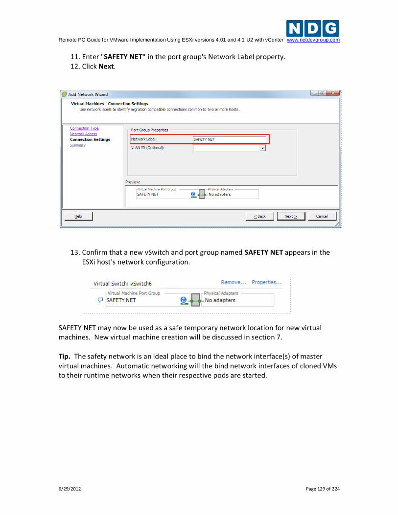
Remote PC Guide for VMware Implementation Using ESXi versions 4.01 and 4.1 U2 with vCenter www.netdevgroup.com
6/29/2012 Page 129 of 224
11. Enter "SAFETY NET" in the port group's Network Label property. 12. Click Next.
13. Confirm that a new vSwitch and port group named SAFETY NET appears in the ESXi host's network configuration.
SAFETY NET may now be used as a safe temporary network location for new virtual machines. New virtual machine creation will be discussed in section 7. Tip. The safety network is an ideal place to bind the network interface(s) of master virtual machines. Automatic networking will the bind network interfaces of cloned VMs to their runtime networks when their respective pods are started.
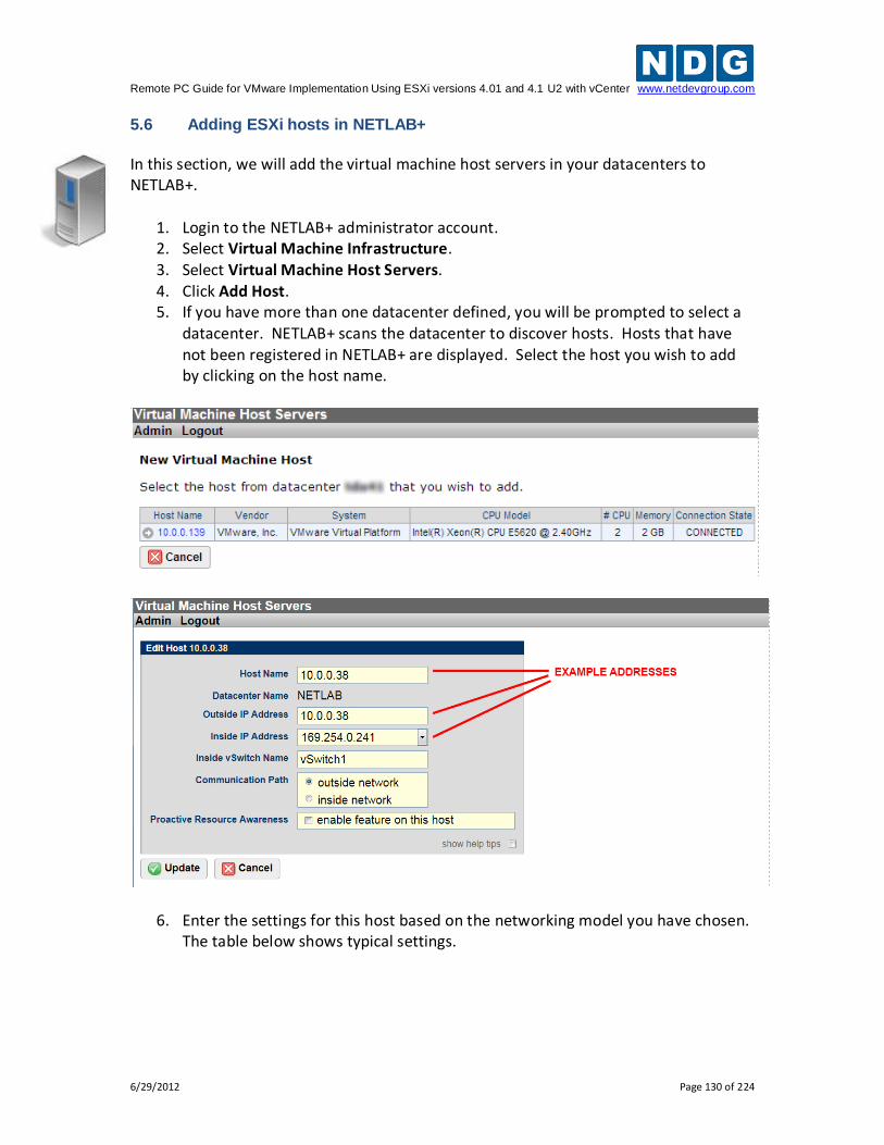
Remote PC Guide for VMware Implementation Using ESXi versions 4.01 and 4.1 U2 with vCenter www.netdevgroup.com
6/29/2012 Page 130 of 224
5.6 Adding ESXi hosts in NETLAB+
In this section, we will add the virtual machine host servers in your datacenters to NETLAB+.
1. Login to the NETLAB+ administrator account. 2. Select Virtual Machine Infrastructure. 3. Select Virtual Machine Host Servers. 4. Click Add Host. 5. If you have more than one datacenter defined, you will be prompted to select a
datacenter. NETLAB+ scans the datacenter to discover hosts. Hosts that have not been registered in NETLAB+ are displayed. Select the host you wish to add by clicking on the host name.
6. Enter the settings for this host based on the networking model you have chosen. The table below shows typical settings.
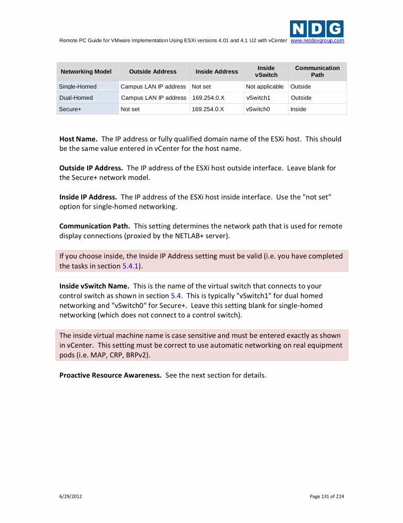
Remote PC Guide for VMware Implementation Using ESXi versions 4.01 and 4.1 U2 with vCenter www.netdevgroup.com
6/29/2012 Page 131 of 224
Networking Model Outside Address Inside Address Inside
vSwitch Communication
Path
Single-Homed Campus LAN IP address Not set Not applicable Outside
Dual-Homed Campus LAN IP address 169.254.0.X vSwitch1 Outside
Secure+ Not set 169.254.0.X vSwitch0 Inside
Host Name. The IP address or fully qualified domain name of the ESXi host. This should be the same value entered in vCenter for the host name. Outside IP Address. The IP address of the ESXi host outside interface. Leave blank for the Secure+ network model. Inside IP Address. The IP address of the ESXi host inside interface. Use the "not set" option for single-homed networking. Communication Path. This setting determines the network path that is used for remote display connections (proxied by the NETLAB+ server).
If you choose inside, the Inside IP Address setting must be valid (i.e. you have completed
the tasks in section 5.4.1).
Inside vSwitch Name. This is the name of the virtual switch that connects to your control switch as shown in section 5.4. This is typically "vSwitch1" for dual homed networking and "vSwitch0" for Secure+. Leave this setting blank for single-homed networking (which does not connect to a control switch).
The inside virtual machine name is case sensitive and must be entered exactly as shown in vCenter. This setting must be correct to use automatic networking on real equipment pods (i.e. MAP, CRP, BRPv2).
Proactive Resource Awareness. See the next section for details.
Remote PC Guide for VMware Implementation Using ESXi versions 4.01 and 4.1 U2 with vCenter www.netdevgroup.com
6/29/2012 Page 132 of 224
5.7 Proactive Resource Awareness
Proactive Resource Awareness (PRA) allows you to time-share virtualization servers using the NETLAB+ scheduler. PRA is designed with 3 goals in mind.
1. Ensure a quality lab experience for all trainees by reserving CPU and memory resources on VM servers at the scheduled lab times. This proactively prevents the VM servers from becoming overloaded and unresponsive.
2. Increase the number of trainees that you can run through your training programs by spreading out the trainee lab sessions over time.
3. Reduce costs of your training programs by using fewer virtualization servers. For each VM server in your inventory, you may set 3 limits.
Total number of active virtual machines
Active number of virtual CPUs
Active maximum memory usage With these limits defined, the scheduler will proactively manage the servers CPU and memory resources. If scheduling a particular pod would exceed one of the set limits in a 30 minute time slot, the pod cannot be scheduled at that time and the limitation will be clearly indicated on the scheduler. PRA is enabled in Virtual Machine Host Servers on a per host basis. You can enable PRA when adding a host or editing the host settings of an existing host. Administrator Account > Virtual Machine Inventory > Virtual Machine Host Servers
The values you set for PRA will depend on your host server specifications and the types of workloads that you run on your servers. Proactive Resource Awareness is a scheduling algorithm based on workload forecasting; it does not monitor real time workload. PRA assumes that all virtual machines running on a host server are under the control of NETLAB+; it does not account for VMs that are powered on independently of NETLAB+.
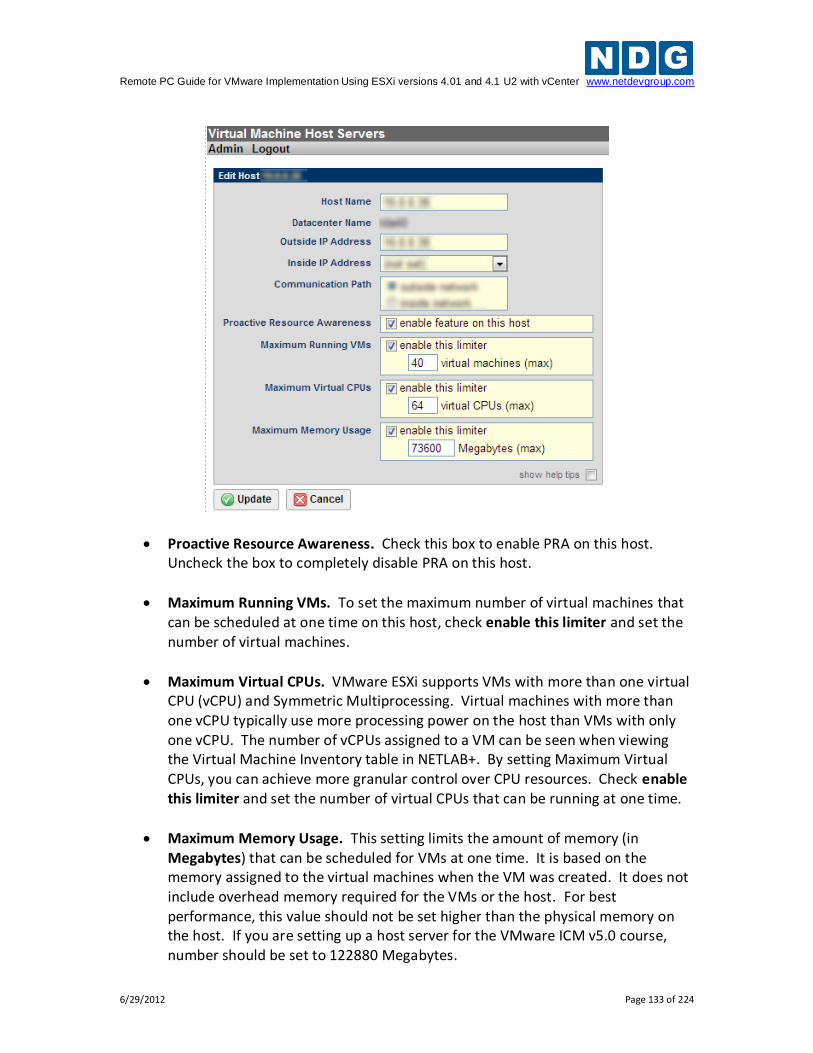
Remote PC Guide for VMware Implementation Using ESXi versions 4.01 and 4.1 U2 with vCenter www.netdevgroup.com
6/29/2012 Page 133 of 224
Proactive Resource Awareness. Check this box to enable PRA on this host. Uncheck the box to completely disable PRA on this host.
Maximum Running VMs. To set the maximum number of virtual machines that can be scheduled at one time on this host, check enable this limiter and set the number of virtual machines.
Maximum Virtual CPUs. VMware ESXi supports VMs with more than one virtual CPU (vCPU) and Symmetric Multiprocessing. Virtual machines with more than one vCPU typically use more processing power on the host than VMs with only one vCPU. The number of vCPUs assigned to a VM can be seen when viewing the Virtual Machine Inventory table in NETLAB+. By setting Maximum Virtual CPUs, you can achieve more granular control over CPU resources. Check enable this limiter and set the number of virtual CPUs that can be running at one time.
Maximum Memory Usage. This setting limits the amount of memory (in Megabytes) that can be scheduled for VMs at one time. It is based on the memory assigned to the virtual machines when the VM was created. It does not include overhead memory required for the VMs or the host. For best performance, this value should not be set higher than the physical memory on the host. If you are setting up a host server for the VMware ICM v5.0 course, number should be set to 122880 Megabytes.
Remote PC Guide for VMware Implementation Using ESXi versions 4.01 and 4.1 U2 with vCenter www.netdevgroup.com
6/29/2012 Page 134 of 224
6 vCenter Update Manager
Depending on the installation method you selected in section 4.6, please choose the appropriate sub section below. You will need to perform updates if you installed an older version of ESXi on your host
machines (i.e. ESXi 4.1 or ESXi 4.1 U1).
NETLAB+ requires you to use ESXi 4.1 U2. This section will assist in making sure you are at the appropriate version.
VMware vCenter Update Manager requires Internet access to update ESXi hosts. If you do not have Internet access on your vCenter Server machine, there are ways to download the patches from VMware.
Refer to the VMware vCenter Update Manager Installation and Administration Guide
from VMware for more information.
VMware vCenter Update Manager helps the administrator keep VMware components up to date. In this section, you will be installing vCenter Update Manager and perform updates to assure you are at the correct patch level for NETLAB+ operation. If you are installing vCenter Update Manager on a physical machine, you can burn the vCenter Server .iso image to a DVD. Insert the DVD into the CD/DVD drive. If you are installing to a virtual machine, upload the vCenter Server image file to the ESXi datastore and add the CD to the virtual machine’s CD/DVD drive.
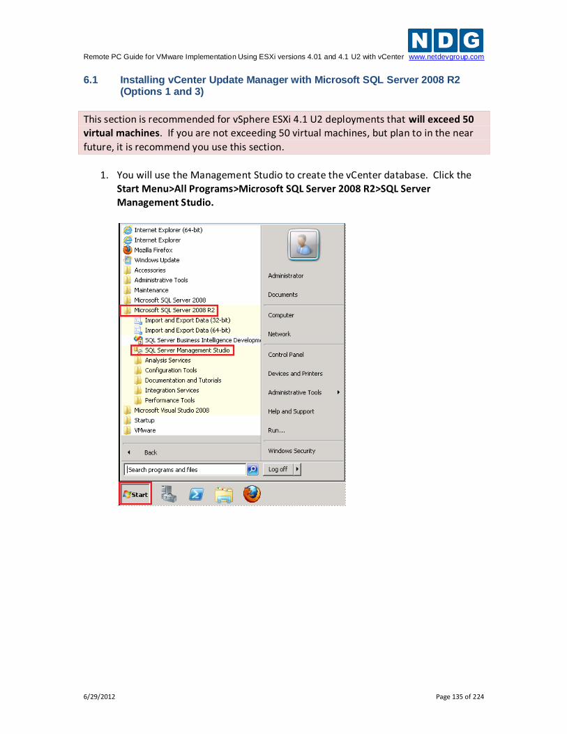
Remote PC Guide for VMware Implementation Using ESXi versions 4.01 and 4.1 U2 with vCenter www.netdevgroup.com
6/29/2012 Page 135 of 224
6.1 Installing vCenter Update Manager with Microsoft SQL Server 2008 R2 (Options 1 and 3)
This section is recommended for vSphere ESXi 4.1 U2 deployments that will exceed 50 virtual machines. If you are not exceeding 50 virtual machines, but plan to in the near
future, it is recommend you use this section.
1. You will use the Management Studio to create the vCenter database. Click the
Start Menu>All Programs>Microsoft SQL Server 2008 R2>SQL Server Management Studio.
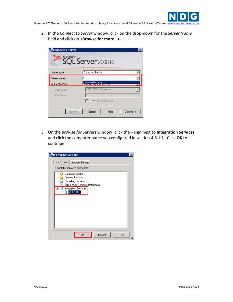
Remote PC Guide for VMware Implementation Using ESXi versions 4.01 and 4.1 U2 with vCenter www.netdevgroup.com
6/29/2012 Page 136 of 224
2. In the Connect to Server window, click on the drop-down for the Server Name field and click on <Browse for more…>.
3. On the Browse for Servers window, click the + sign next to Integration Services and click the computer name you configured in section 4.6.1.1. Click OK to continue.
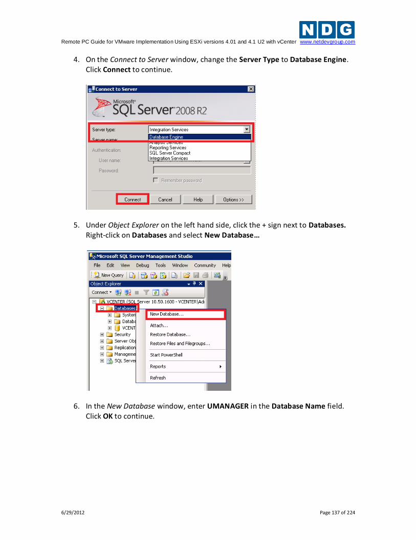
Remote PC Guide for VMware Implementation Using ESXi versions 4.01 and 4.1 U2 with vCenter www.netdevgroup.com
6/29/2012 Page 137 of 224
4. On the Connect to Server window, change the Server Type to Database Engine. Click Connect to continue.
5. Under Object Explorer on the left hand side, click the + sign next to Databases. Right-click on Databases and select New Database…
6. In the New Database window, enter UMANAGER in the Database Name field. Click OK to continue.
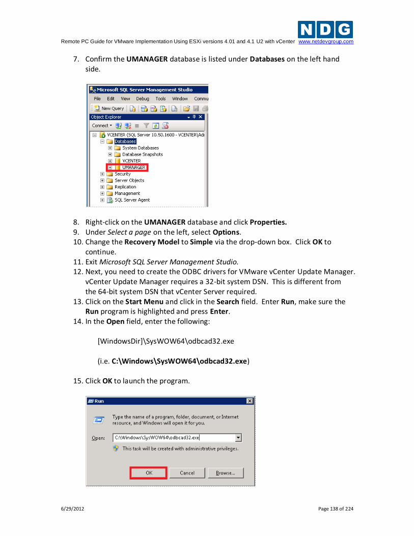
Remote PC Guide for VMware Implementation Using ESXi versions 4.01 and 4.1 U2 with vCenter www.netdevgroup.com
6/29/2012 Page 138 of 224
7. Confirm the UMANAGER database is listed under Databases on the left hand side.
8. Right-click on the UMANAGER database and click Properties. 9. Under Select a page on the left, select Options. 10. Change the Recovery Model to Simple via the drop-down box. Click OK to
continue. 11. Exit Microsoft SQL Server Management Studio. 12. Next, you need to create the ODBC drivers for VMware vCenter Update Manager.
vCenter Update Manager requires a 32-bit system DSN. This is different from the 64-bit system DSN that vCenter Server required.
13. Click on the Start Menu and click in the Search field. Enter Run, make sure the Run program is highlighted and press Enter.
14. In the Open field, enter the following: [WindowsDir]\SysWOW64\odbcad32.exe (i.e. C:\Windows\SysWOW64\odbcad32.exe)
15. Click OK to launch the program.
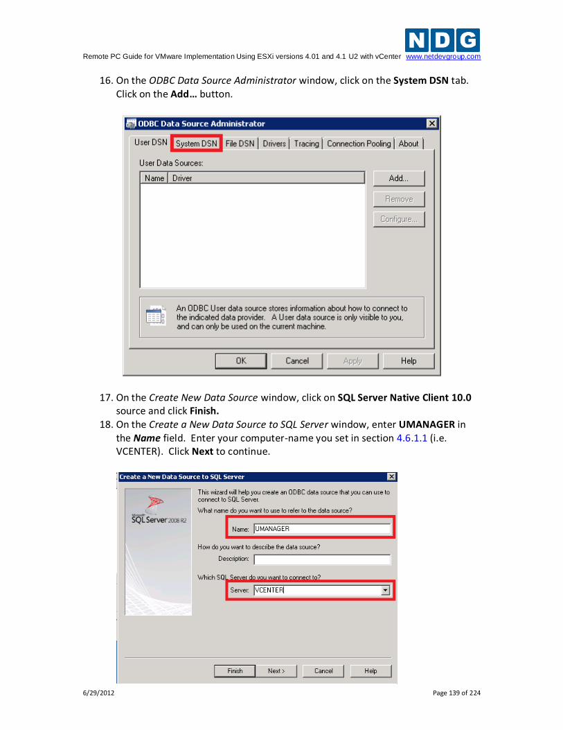
Remote PC Guide for VMware Implementation Using ESXi versions 4.01 and 4.1 U2 with vCenter www.netdevgroup.com
6/29/2012 Page 139 of 224
16. On the ODBC Data Source Administrator window, click on the System DSN tab. Click on the Add… button.
17. On the Create New Data Source window, click on SQL Server Native Client 10.0 source and click Finish.
18. On the Create a New Data Source to SQL Server window, enter UMANAGER in the Name field. Enter your computer-name you set in section 4.6.1.1 (i.e. VCENTER). Click Next to continue.
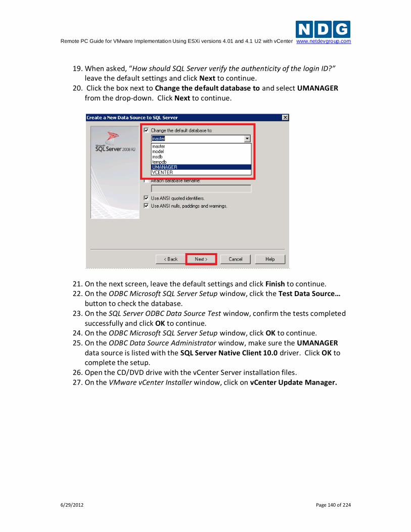
Remote PC Guide for VMware Implementation Using ESXi versions 4.01 and 4.1 U2 with vCenter www.netdevgroup.com
6/29/2012 Page 140 of 224
19. When asked, “How should SQL Server verify the authenticity of the login ID?”
leave the default settings and click Next to continue. 20. Click the box next to Change the default database to and select UMANAGER
from the drop-down. Click Next to continue.
21. On the next screen, leave the default settings and click Finish to continue. 22. On the ODBC Microsoft SQL Server Setup window, click the Test Data Source…
button to check the database. 23. On the SQL Server ODBC Data Source Test window, confirm the tests completed
successfully and click OK to continue. 24. On the ODBC Microsoft SQL Server Setup window, click OK to continue. 25. On the ODBC Data Source Administrator window, make sure the UMANAGER
data source is listed with the SQL Server Native Client 10.0 driver. Click OK to complete the setup.
26. Open the CD/DVD drive with the vCenter Server installation files. 27. On the VMware vCenter Installer window, click on vCenter Update Manager.
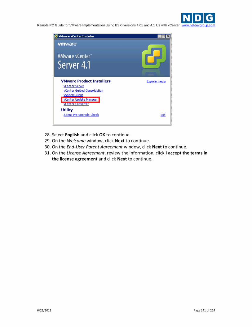
Remote PC Guide for VMware Implementation Using ESXi versions 4.01 and 4.1 U2 with vCenter www.netdevgroup.com
6/29/2012 Page 141 of 224
28. Select English and click OK to continue. 29. On the Welcome window, click Next to continue. 30. On the End-User Patent Agreement window, click Next to continue. 31. On the License Agreement, review the information, click I accept the terms in
the license agreement and click Next to continue.
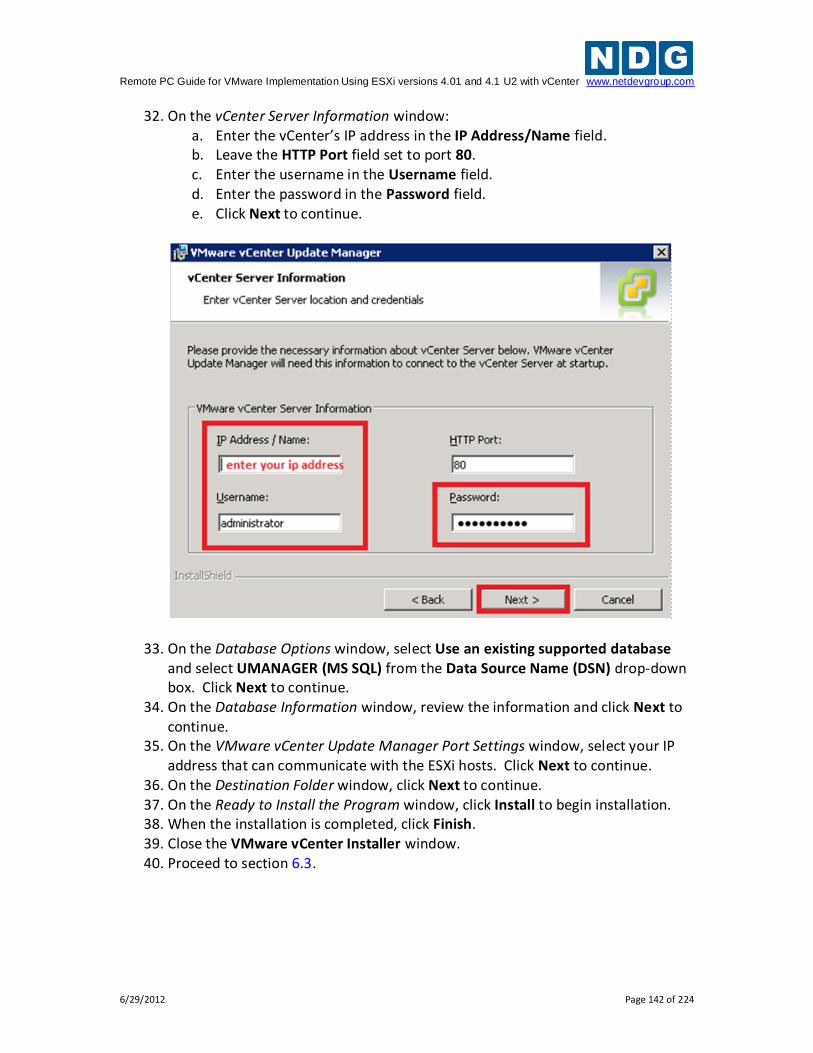
Remote PC Guide for VMware Implementation Using ESXi versions 4.01 and 4.1 U2 with vCenter www.netdevgroup.com
6/29/2012 Page 142 of 224
32. On the vCenter Server Information window: a. Enter the vCenter’s IP address in the IP Address/Name field. b. Leave the HTTP Port field set to port 80. c. Enter the username in the Username field. d. Enter the password in the Password field. e. Click Next to continue.
33. On the Database Options window, select Use an existing supported database and select UMANAGER (MS SQL) from the Data Source Name (DSN) drop-down box. Click Next to continue.
34. On the Database Information window, review the information and click Next to continue.
35. On the VMware vCenter Update Manager Port Settings window, select your IP address that can communicate with the ESXi hosts. Click Next to continue.
36. On the Destination Folder window, click Next to continue. 37. On the Ready to Install the Program window, click Install to begin installation. 38. When the installation is completed, click Finish. 39. Close the VMware vCenter Installer window. 40. Proceed to section 6.3.
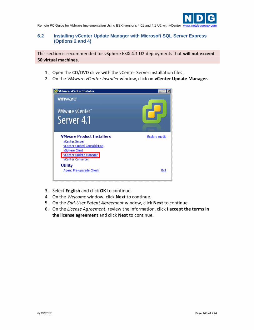
Remote PC Guide for VMware Implementation Using ESXi versions 4.01 and 4.1 U2 with vCenter www.netdevgroup.com
6/29/2012 Page 143 of 224
6.2 Installing vCenter Update Manager with Microsoft SQL Server Express (Options 2 and 4)
This section is recommended for vSphere ESXi 4.1 U2 deployments that will not exceed
50 virtual machines.
1. Open the CD/DVD drive with the vCenter Server installation files. 2. On the VMware vCenter Installer window, click on vCenter Update Manager.
3. Select English and click OK to continue. 4. On the Welcome window, click Next to continue. 5. On the End-User Patent Agreement window, click Next to continue. 6. On the License Agreement, review the information, click I accept the terms in
the license agreement and click Next to continue.
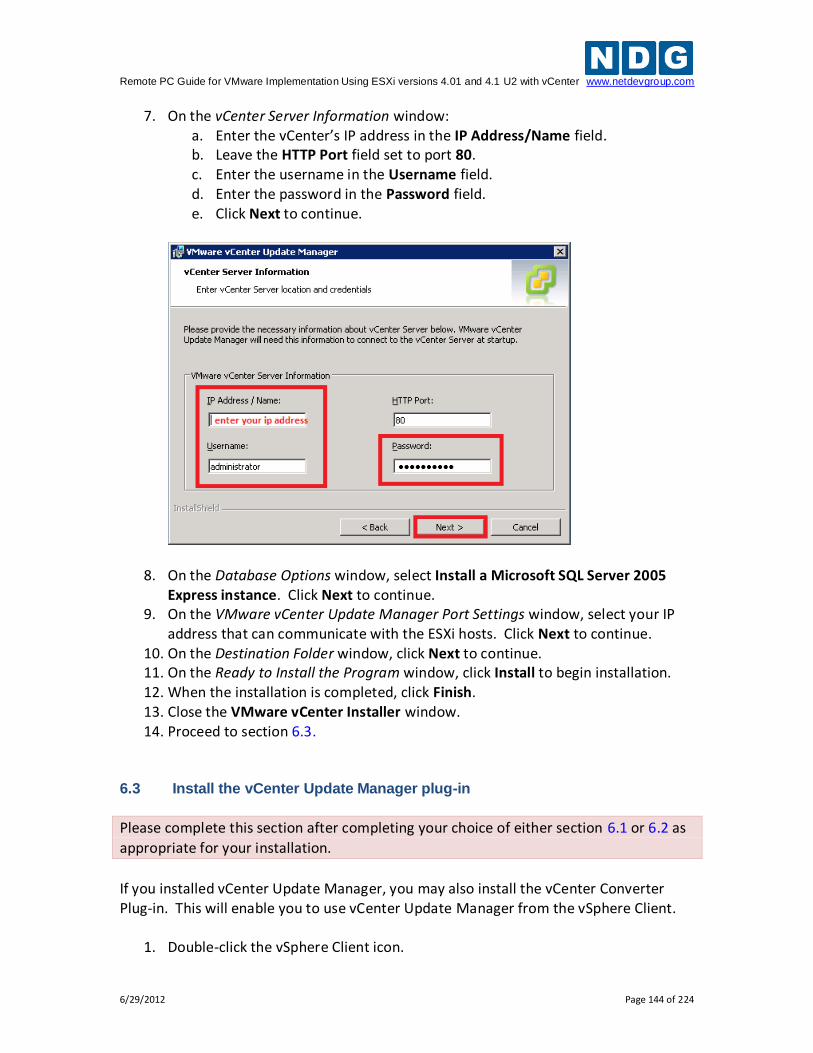
Remote PC Guide for VMware Implementation Using ESXi versions 4.01 and 4.1 U2 with vCenter www.netdevgroup.com
6/29/2012 Page 144 of 224
7. On the vCenter Server Information window: a. Enter the vCenter’s IP address in the IP Address/Name field. b. Leave the HTTP Port field set to port 80. c. Enter the username in the Username field. d. Enter the password in the Password field. e. Click Next to continue.
8. On the Database Options window, select Install a Microsoft SQL Server 2005 Express instance. Click Next to continue.
9. On the VMware vCenter Update Manager Port Settings window, select your IP address that can communicate with the ESXi hosts. Click Next to continue.
10. On the Destination Folder window, click Next to continue. 11. On the Ready to Install the Program window, click Install to begin installation. 12. When the installation is completed, click Finish. 13. Close the VMware vCenter Installer window. 14. Proceed to section 6.3.
6.3 Install the vCenter Update Manager plug-in
Please complete this section after completing your choice of either section 6.1 or 6.2 as
appropriate for your installation.
If you installed vCenter Update Manager, you may also install the vCenter Converter Plug-in. This will enable you to use vCenter Update Manager from the vSphere Client.
1. Double-click the vSphere Client icon.
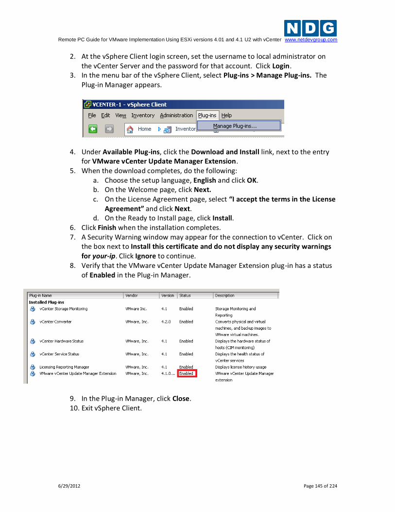
Remote PC Guide for VMware Implementation Using ESXi versions 4.01 and 4.1 U2 with vCenter www.netdevgroup.com
6/29/2012 Page 145 of 224
2. At the vSphere Client login screen, set the username to local administrator on the vCenter Server and the password for that account. Click Login.
3. In the menu bar of the vSphere Client, select Plug-ins > Manage Plug-ins. The Plug-in Manager appears.
4. Under Available Plug-ins, click the Download and Install link, next to the entry for VMware vCenter Update Manager Extension.
5. When the download completes, do the following: a. Choose the setup language, English and click OK. b. On the Welcome page, click Next. c. On the License Agreement page, select “I accept the terms in the License
Agreement” and click Next. d. On the Ready to Install page, click Install.
6. Click Finish when the installation completes. 7. A Security Warning window may appear for the connection to vCenter. Click on
the box next to Install this certificate and do not display any security warnings for your-ip. Click Ignore to continue.
8. Verify that the VMware vCenter Update Manager Extension plug-in has a status of Enabled in the Plug-in Manager.
9. In the Plug-in Manager, click Close. 10. Exit vSphere Client.
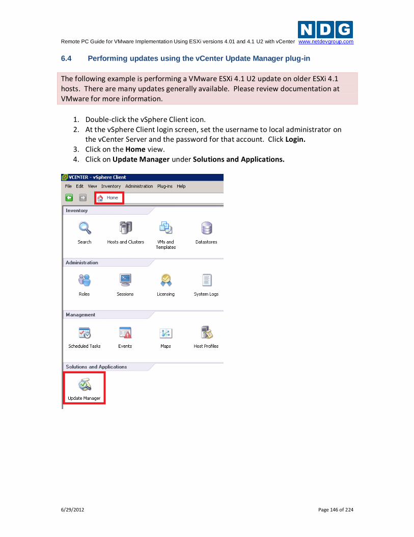
Remote PC Guide for VMware Implementation Using ESXi versions 4.01 and 4.1 U2 with vCenter www.netdevgroup.com
6/29/2012 Page 146 of 224
6.4 Performing updates using the vCenter Update Manager plug-in
The following example is performing a VMware ESXi 4.1 U2 update on older ESXi 4.1 hosts. There are many updates generally available. Please review documentation at VMware for more information.
1. Double-click the vSphere Client icon. 2. At the vSphere Client login screen, set the username to local administrator on
the vCenter Server and the password for that account. Click Login. 3. Click on the Home view. 4. Click on Update Manager under Solutions and Applications.
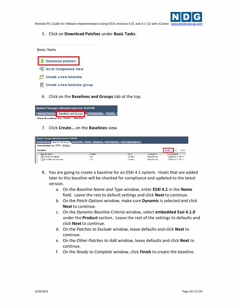
Remote PC Guide for VMware Implementation Using ESXi versions 4.01 and 4.1 U2 with vCenter www.netdevgroup.com
6/29/2012 Page 147 of 224
5. Click on Download Patches under Basic Tasks.
6. Click on the Baselines and Groups tab at the top.
7. Click Create… on the Baselines view.
8. You are going to create a baseline for an ESXi 4.1 system. Hosts that are added later to this baseline will be checked for compliance and updated to the latest version.
a. On the Baseline Name and Type window, enter ESXi 4.1 in the Name field. Leave the rest to default settings and click Next to continue.
b. On the Patch Options window, make sure Dynamic is selected and click Next to continue.
c. On the Dynamic Baseline Criteria window, select embedded Esxi 4.1.0 under the Product section. Leave the rest of the settings to defaults and click Next to continue.
d. On the Patches to Exclude window, leave defaults and click Next to continue.
e. On the Other Patches to Add window, leave defaults and click Next to continue.
f. On the Ready to Complete window, click Finish to create the baseline.
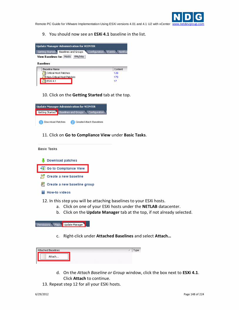
Remote PC Guide for VMware Implementation Using ESXi versions 4.01 and 4.1 U2 with vCenter www.netdevgroup.com
6/29/2012 Page 148 of 224
9. You should now see an ESXi 4.1 baseline in the list.
10. Click on the Getting Started tab at the top.
11. Click on Go to Compliance View under Basic Tasks.
12. In this step you will be attaching baselines to your ESXi hosts.
a. Click on one of your ESXi hosts under the NETLAB datacenter. b. Click on the Update Manager tab at the top, if not already selected.
c. Right-click under Attached Baselines and select Attach…
d. On the Attach Baseline or Group window, click the box next to ESXi 4.1. Click Attach to continue.
13. Repeat step 12 for all your ESXi hosts.
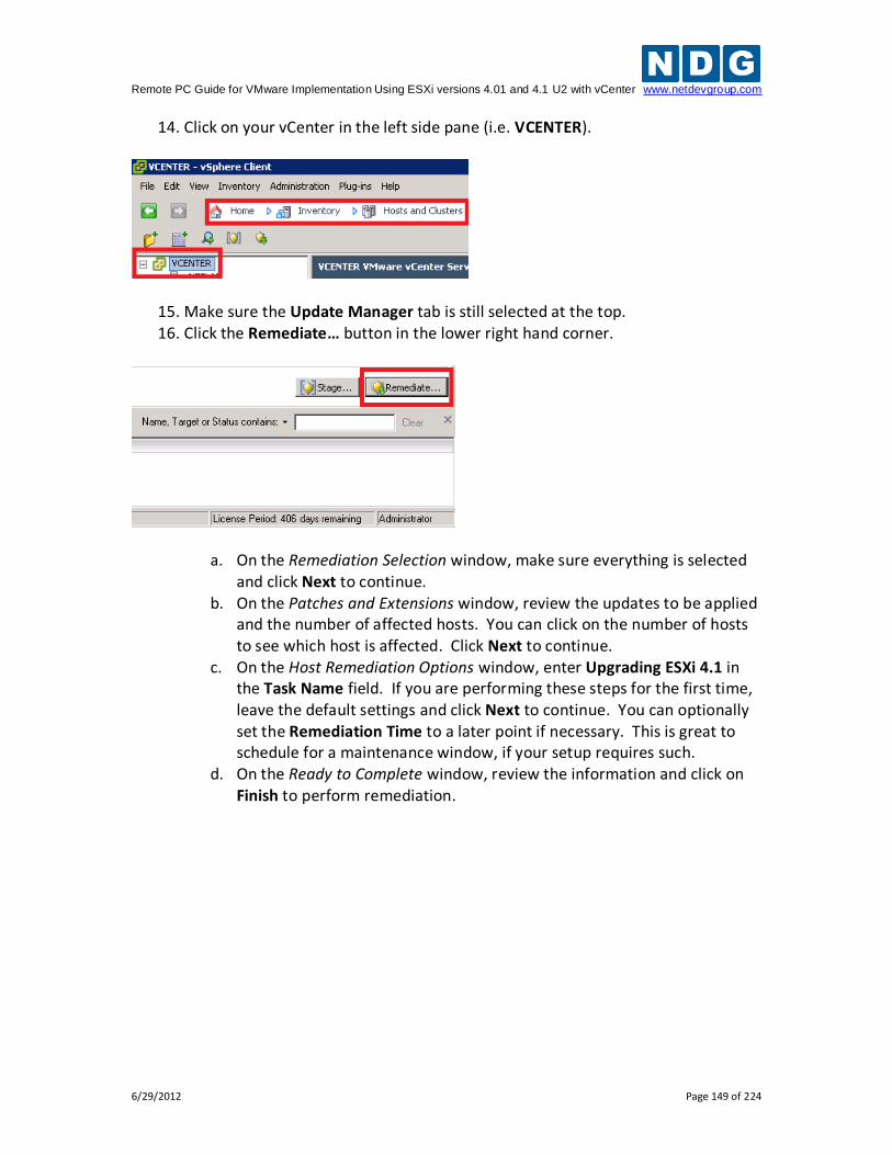
Remote PC Guide for VMware Implementation Using ESXi versions 4.01 and 4.1 U2 with vCenter www.netdevgroup.com
6/29/2012 Page 149 of 224
14. Click on your vCenter in the left side pane (i.e. VCENTER).
15. Make sure the Update Manager tab is still selected at the top. 16. Click the Remediate… button in the lower right hand corner.
a. On the Remediation Selection window, make sure everything is selected and click Next to continue.
b. On the Patches and Extensions window, review the updates to be applied and the number of affected hosts. You can click on the number of hosts to see which host is affected. Click Next to continue.
c. On the Host Remediation Options window, enter Upgrading ESXi 4.1 in the Task Name field. If you are performing these steps for the first time, leave the default settings and click Next to continue. You can optionally set the Remediation Time to a later point if necessary. This is great to schedule for a maintenance window, if your setup requires such.
d. On the Ready to Complete window, review the information and click on Finish to perform remediation.
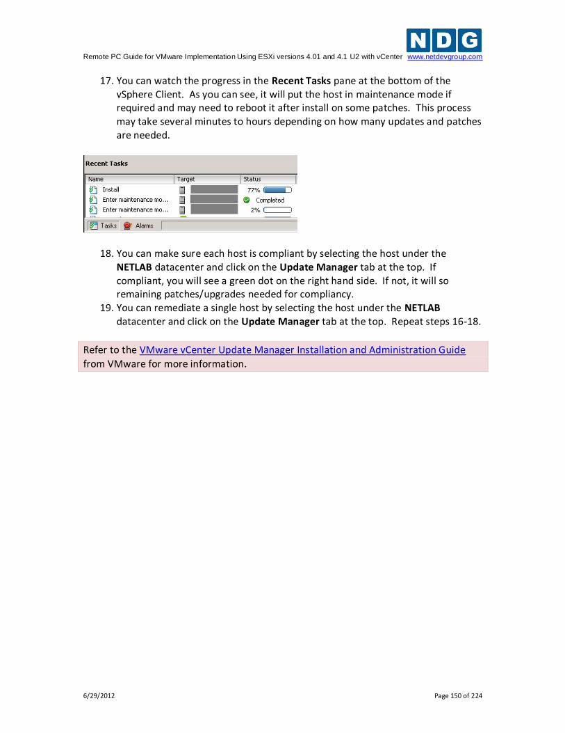
Remote PC Guide for VMware Implementation Using ESXi versions 4.01 and 4.1 U2 with vCenter www.netdevgroup.com
6/29/2012 Page 150 of 224
17. You can watch the progress in the Recent Tasks pane at the bottom of the vSphere Client. As you can see, it will put the host in maintenance mode if required and may need to reboot it after install on some patches. This process may take several minutes to hours depending on how many updates and patches are needed.
18. You can make sure each host is compliant by selecting the host under the NETLAB datacenter and click on the Update Manager tab at the top. If compliant, you will see a green dot on the right hand side. If not, it will so remaining patches/upgrades needed for compliancy.
19. You can remediate a single host by selecting the host under the NETLAB datacenter and click on the Update Manager tab at the top. Repeat steps 16-18.
Refer to the VMware vCenter Update Manager Installation and Administration Guide
from VMware for more information.
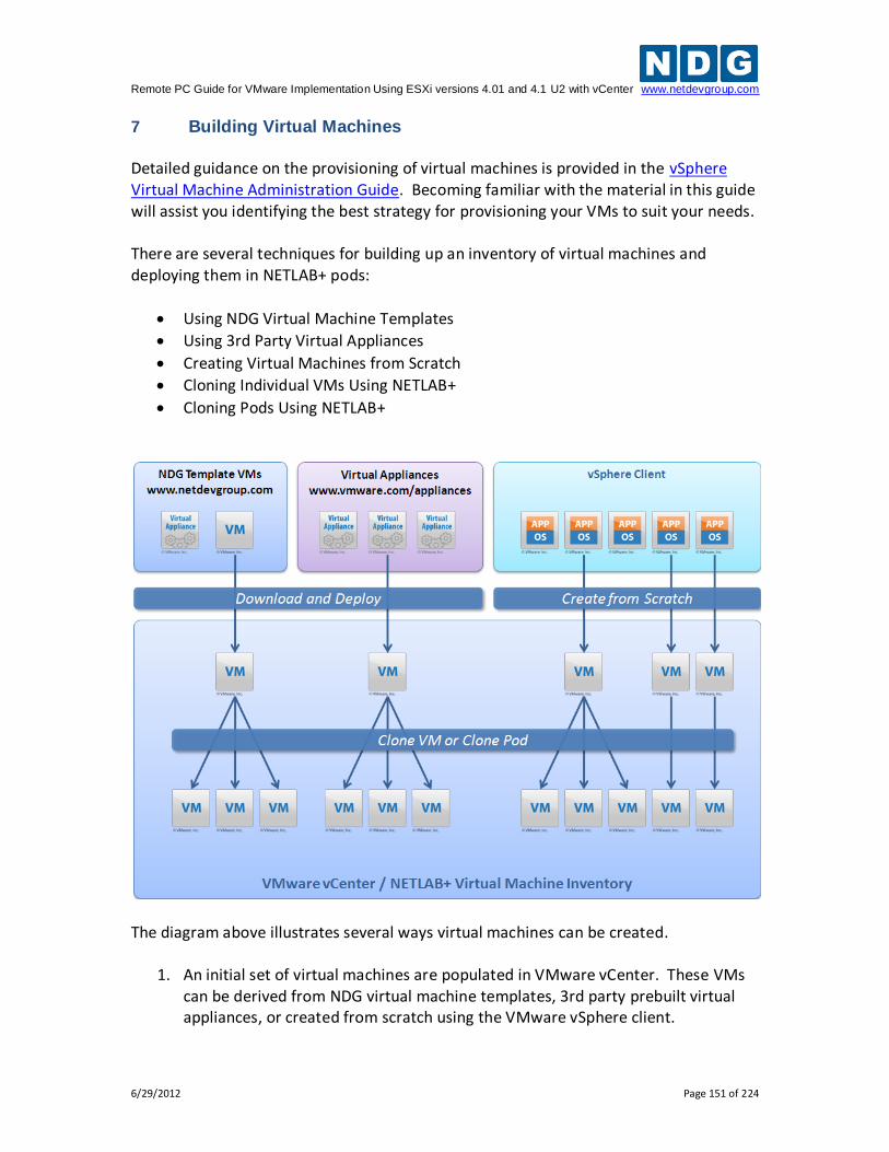
Remote PC Guide for VMware Implementation Using ESXi versions 4.01 and 4.1 U2 with vCenter www.netdevgroup.com
6/29/2012 Page 151 of 224
7 Building Virtual Machines Detailed guidance on the provisioning of virtual machines is provided in the vSphere Virtual Machine Administration Guide. Becoming familiar with the material in this guide will assist you identifying the best strategy for provisioning your VMs to suit your needs. There are several techniques for building up an inventory of virtual machines and deploying them in NETLAB+ pods:
Using NDG Virtual Machine Templates
Using 3rd Party Virtual Appliances
Creating Virtual Machines from Scratch
Cloning Individual VMs Using NETLAB+
Cloning Pods Using NETLAB+
The diagram above illustrates several ways virtual machines can be created.
1. An initial set of virtual machines are populated in VMware vCenter. These VMs can be derived from NDG virtual machine templates, 3rd party prebuilt virtual appliances, or created from scratch using the VMware vSphere client.
Remote PC Guide for VMware Implementation Using ESXi versions 4.01 and 4.1 U2 with vCenter www.netdevgroup.com
6/29/2012 Page 152 of 224
2. The initial set of VMs is imported into the NETLAB+ virtual machine inventory.
3. Individual VMs can be cloned directly from NETLAB+ to create more virtual machines. Cloned virtual machines can be modified to perform different roles.
4. After virtual machines are assigned to a NETLAB+ pod, the pod and its virtual machines can be cloned in one operation.
In this section, you will learn three methods that can be used to create an initial set of virtual machines, starting from an empty inventory:
Using NDG Template Virtual Machines
Using 3rd Party Virtual Appliances
Creating Virtual Machines from Scratch This section also discusses two important tasks that apply to all virtual machines:
Configuring virtual machines to provide optimal user performance.
Taking virtual machine snapshots that can be used to place pods in a clean state. Detailed guidance on the provisioning of virtual machines is provided in the vSphere Virtual Machine Administration Guide. Becoming familiar with the material in this guide will assist you in identifying the best strategy of provisioning your VMs to suit your needs.
All tasks in this section are performed using only the VMware vSphere client.
In section 8, you will learn how to import your initial set of virtual machines into NETLAB+, then create additional virtual machines quickly using cloning techniques.
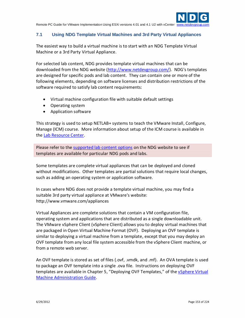
Remote PC Guide for VMware Implementation Using ESXi versions 4.01 and 4.1 U2 with vCenter www.netdevgroup.com
6/29/2012 Page 153 of 224
7.1 Using NDG Template Virtual Machines and 3rd Party Virtual Appliances
The easiest way to build a virtual machine is to start with an NDG Template Virtual Machine or a 3rd Party Virtual Appliance. For selected lab content, NDG provides template virtual machines that can be downloaded from the NDG website (http://www.netdevgroup.com/). NDG's templates are designed for specific pods and lab content. They can contain one or more of the following elements, depending on software licenses and distribution restrictions of the software required to satisfy lab content requirements:
Virtual machine configuration file with suitable default settings
Operating system
Application software This strategy is used to setup NETLAB+ systems to teach the VMware Install, Configure, Manage (ICM) course. More information about setup of the ICM course is available in the Lab Resource Center.
Please refer to the supported lab content options on the NDG website to see if
templates are available for particular NDG pods and labs.
Some templates are complete virtual appliances that can be deployed and cloned without modifications. Other templates are partial solutions that require local changes, such as adding an operating system or application software. In cases where NDG does not provide a template virtual machine, you may find a suitable 3rd party virtual appliance at VMware's website: http://www.vmware.com/appliances Virtual Appliances are complete solutions that contain a VM configuration file, operating system and applications that are distributed as a single downloadable unit. The VMware vSphere Client (vSphere Client) allows you to deploy virtual machines that are packaged in Open Virtual Machine Format (OVF). Deploying an OVF template is similar to deploying a virtual machine from a template, except that you may deploy an OVF template from any local file system accessible from the vSphere Client machine, or from a remote web server. An OVF template is stored as set of files (.ovf, .vmdk, and .mf). An OVA template is used to package an OVF template into a single .ova file. Instructions on deploying OVF templates are available in Chapter 5, “Deploying OVF Templates,” of the vSphere Virtual Machine Administration Guide.
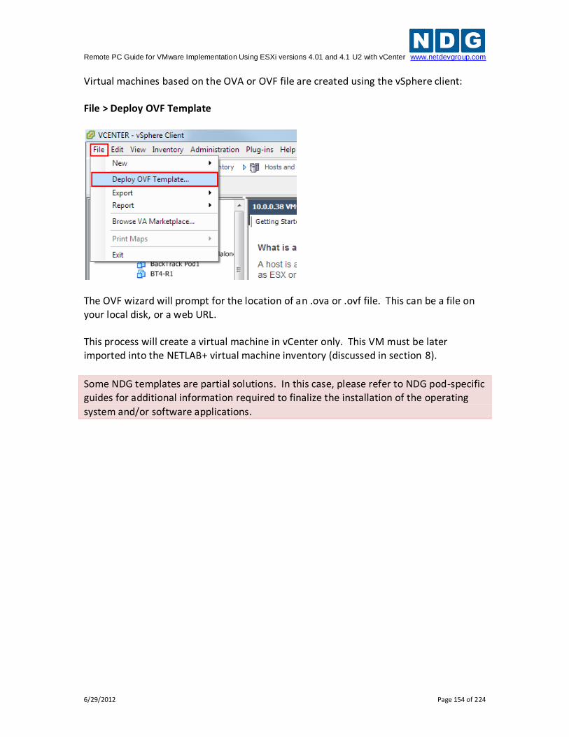
Remote PC Guide for VMware Implementation Using ESXi versions 4.01 and 4.1 U2 with vCenter www.netdevgroup.com
6/29/2012 Page 154 of 224
Virtual machines based on the OVA or OVF file are created using the vSphere client: File > Deploy OVF Template
The OVF wizard will prompt for the location of an .ova or .ovf file. This can be a file on your local disk, or a web URL. This process will create a virtual machine in vCenter only. This VM must be later imported into the NETLAB+ virtual machine inventory (discussed in section 8).
Some NDG templates are partial solutions. In this case, please refer to NDG pod-specific guides for additional information required to finalize the installation of the operating
system and/or software applications.
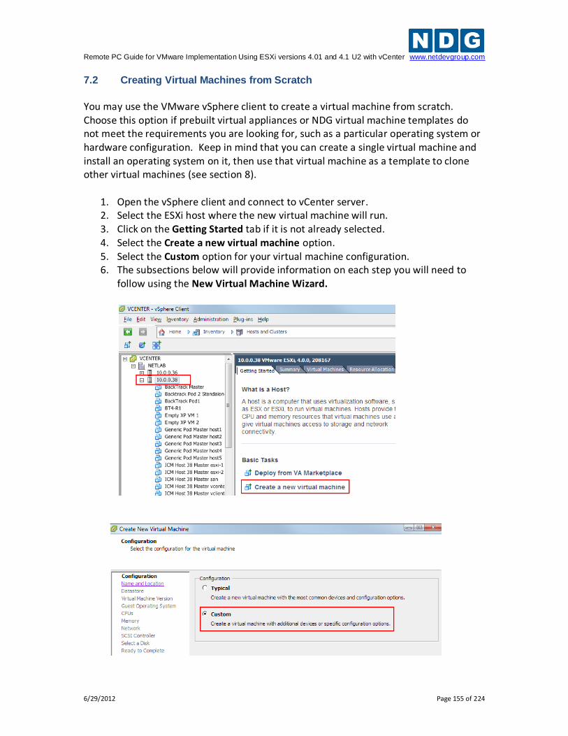
Remote PC Guide for VMware Implementation Using ESXi versions 4.01 and 4.1 U2 with vCenter www.netdevgroup.com
6/29/2012 Page 155 of 224
7.2 Creating Virtual Machines from Scratch
You may use the VMware vSphere client to create a virtual machine from scratch. Choose this option if prebuilt virtual appliances or NDG virtual machine templates do not meet the requirements you are looking for, such as a particular operating system or hardware configuration. Keep in mind that you can create a single virtual machine and install an operating system on it, then use that virtual machine as a template to clone other virtual machines (see section 8).
1. Open the vSphere client and connect to vCenter server. 2. Select the ESXi host where the new virtual machine will run. 3. Click on the Getting Started tab if it is not already selected. 4. Select the Create a new virtual machine option. 5. Select the Custom option for your virtual machine configuration. 6. The subsections below will provide information on each step you will need to
follow using the New Virtual Machine Wizard.
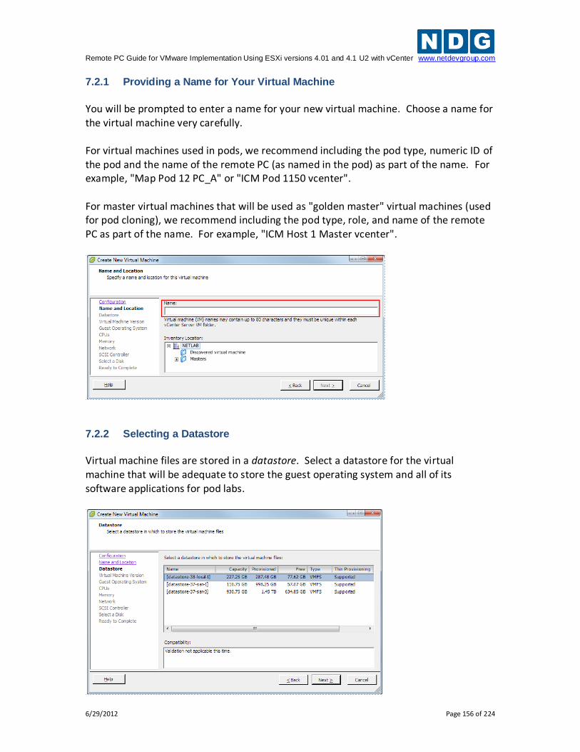
Remote PC Guide for VMware Implementation Using ESXi versions 4.01 and 4.1 U2 with vCenter www.netdevgroup.com
6/29/2012 Page 156 of 224
7.2.1 Providing a Name for Your Virtual Machine
You will be prompted to enter a name for your new virtual machine. Choose a name for the virtual machine very carefully. For virtual machines used in pods, we recommend including the pod type, numeric ID of the pod and the name of the remote PC (as named in the pod) as part of the name. For example, "Map Pod 12 PC_A" or "ICM Pod 1150 vcenter". For master virtual machines that will be used as "golden master" virtual machines (used for pod cloning), we recommend including the pod type, role, and name of the remote PC as part of the name. For example, "ICM Host 1 Master vcenter".
7.2.2 Selecting a Datastore
Virtual machine files are stored in a datastore. Select a datastore for the virtual machine that will be adequate to store the guest operating system and all of its software applications for pod labs.
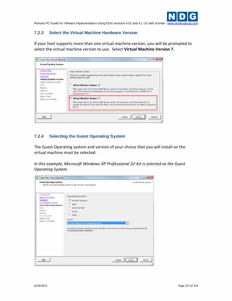
Remote PC Guide for VMware Implementation Using ESXi versions 4.01 and 4.1 U2 with vCenter www.netdevgroup.com
6/29/2012 Page 157 of 224
7.2.3 Select the Virtual Machine Hardware Version
If your host supports more than one virtual machine version, you will be prompted to select the virtual machine version to use. Select Virtual Machine Version 7.
7.2.4 Selecting the Guest Operating System
The Guest Operating system and version of your choice that you will install on the virtual machine must be selected. In this example, Microsoft Windows XP Professional 32-bit is selected as the Guest Operating System.
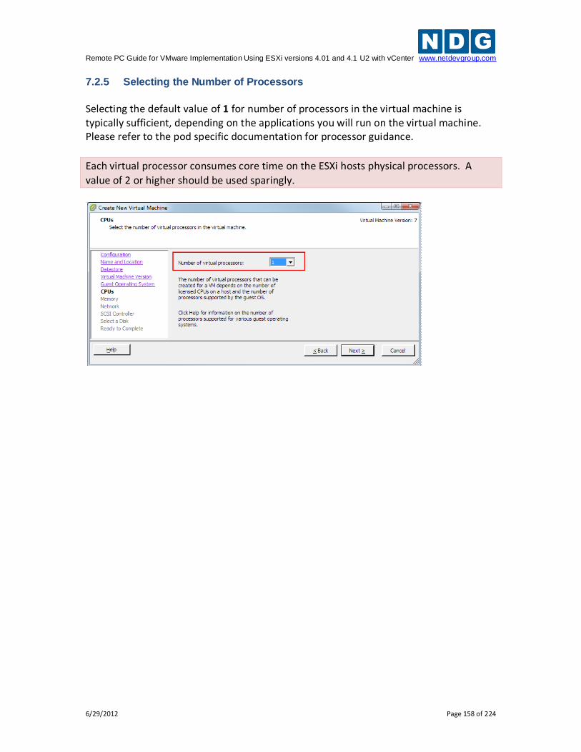
Remote PC Guide for VMware Implementation Using ESXi versions 4.01 and 4.1 U2 with vCenter www.netdevgroup.com
6/29/2012 Page 158 of 224
7.2.5 Selecting the Number of Processors
Selecting the default value of 1 for number of processors in the virtual machine is typically sufficient, depending on the applications you will run on the virtual machine. Please refer to the pod specific documentation for processor guidance.
Each virtual processor consumes core time on the ESXi hosts physical processors. A
value of 2 or higher should be used sparingly.
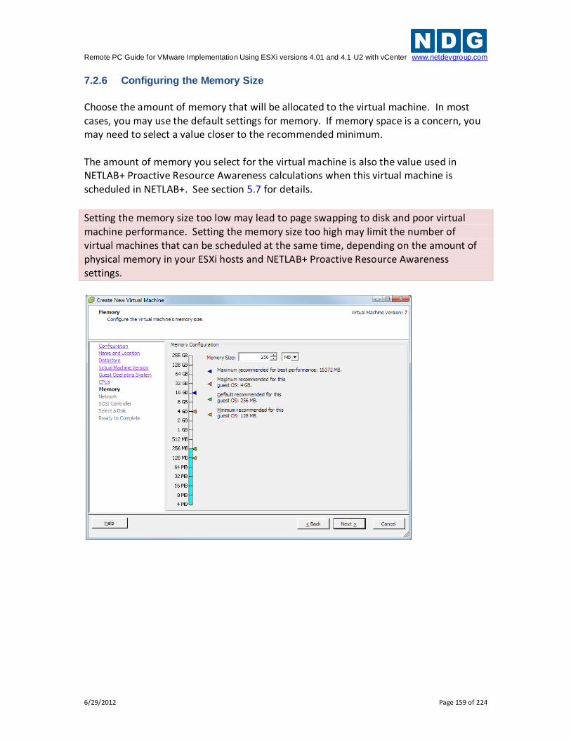
Remote PC Guide for VMware Implementation Using ESXi versions 4.01 and 4.1 U2 with vCenter www.netdevgroup.com
6/29/2012 Page 159 of 224
7.2.6 Configuring the Memory Size
Choose the amount of memory that will be allocated to the virtual machine. In most cases, you may use the default settings for memory. If memory space is a concern, you may need to select a value closer to the recommended minimum. The amount of memory you select for the virtual machine is also the value used in NETLAB+ Proactive Resource Awareness calculations when this virtual machine is scheduled in NETLAB+. See section 5.7 for details.
Setting the memory size too low may lead to page swapping to disk and poor virtual machine performance. Setting the memory size too high may limit the number of virtual machines that can be scheduled at the same time, depending on the amount of physical memory in your ESXi hosts and NETLAB+ Proactive Resource Awareness settings.
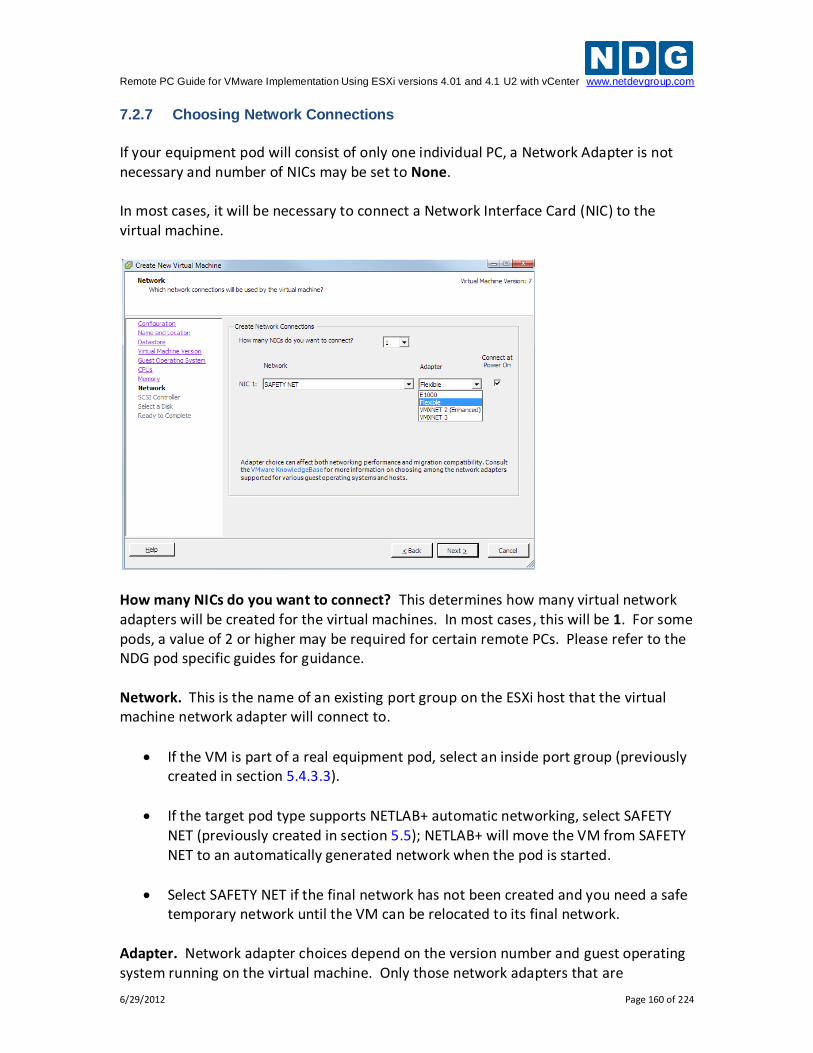
Remote PC Guide for VMware Implementation Using ESXi versions 4.01 and 4.1 U2 with vCenter www.netdevgroup.com
6/29/2012 Page 160 of 224
7.2.7 Choosing Network Connections
If your equipment pod will consist of only one individual PC, a Network Adapter is not necessary and number of NICs may be set to None. In most cases, it will be necessary to connect a Network Interface Card (NIC) to the virtual machine.
How many NICs do you want to connect? This determines how many virtual network adapters will be created for the virtual machines. In most cases, this will be 1. For some pods, a value of 2 or higher may be required for certain remote PCs. Please refer to the NDG pod specific guides for guidance. Network. This is the name of an existing port group on the ESXi host that the virtual machine network adapter will connect to.
If the VM is part of a real equipment pod, select an inside port group (previously created in section 5.4.3.3).
If the target pod type supports NETLAB+ automatic networking, select SAFETY NET (previously created in section 5.5); NETLAB+ will move the VM from SAFETY NET to an automatically generated network when the pod is started.
Select SAFETY NET if the final network has not been created and you need a safe temporary network until the VM can be relocated to its final network.
Adapter. Network adapter choices depend on the version number and guest operating system running on the virtual machine. Only those network adapters that are
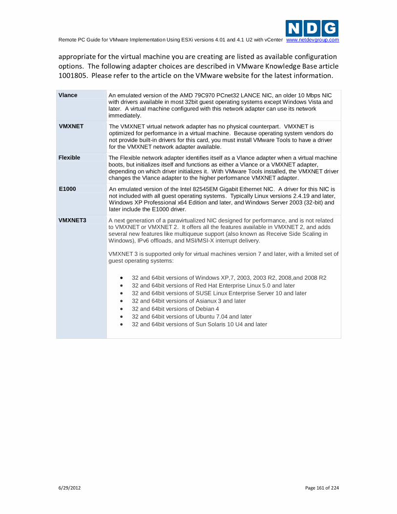
Remote PC Guide for VMware Implementation Using ESXi versions 4.01 and 4.1 U2 with vCenter www.netdevgroup.com
6/29/2012 Page 161 of 224
appropriate for the virtual machine you are creating are listed as available configuration options. The following adapter choices are described in VMware Knowledge Base article 1001805. Please refer to the article on the VMware website for the latest information. Vlance An emulated version of the AMD 79C970 PCnet32 LANCE NIC, an older 10 Mbps NIC
with drivers available in most 32bit guest operating systems except Windows Vista and later. A virtual machine configured with this network adapter can use its network immediately.
VMXNET The VMXNET virtual network adapter has no physical counterpart. VMXNET is optimized for performance in a virtual machine. Because operating system vendors do not provide built-in drivers for this card, you must install VMware Tools to have a driver for the VMXNET network adapter available.
Flexible The Flexible network adapter identifies itself as a Vlance adapter when a virtual machine boots, but initializes itself and functions as either a Vlance or a VMXNET adapter, depending on which driver initializes it. With VMware Tools installed, the VMXNET driver changes the Vlance adapter to the higher performance VMXNET adapter.
E1000 An emulated version of the Intel 82545EM Gigabit Ethernet NIC. A driver for this NIC is not included with all guest operating systems. Typically Linux versions 2.4.19 and later, Windows XP Professional x64 Edition and later, and Windows Server 2003 (32-bit) and later include the E1000 driver.
VMXNET3 A next generation of a paravirtualized NIC designed for performance, and is not related to VMXNET or VMXNET 2. It offers all the features available in VMXNET 2, and adds several new features like multiqueue support (also known as Receive Side Scaling in Windows), IPv6 offloads, and MSI/MSI-X interrupt delivery. VMXNET 3 is supported only for virtual machines version 7 and later, with a limited set of guest operating systems:
32 and 64bit versions of Windows XP,7, 2003, 2003 R2, 2008,and 2008 R2
32 and 64bit versions of Red Hat Enterprise Linux 5.0 and later
32 and 64bit versions of SUSE Linux Enterprise Server 10 and later
32 and 64bit versions of Asianux 3 and later
32 and 64bit versions of Debian 4
32 and 64bit versions of Ubuntu 7.04 and later
32 and 64bit versions of Sun Solaris 10 U4 and later
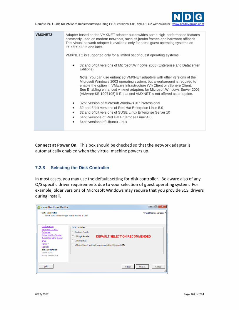
Remote PC Guide for VMware Implementation Using ESXi versions 4.01 and 4.1 U2 with vCenter www.netdevgroup.com
6/29/2012 Page 162 of 224
VMXNET2 Adapter based on the VMXNET adapter but provides some high-performance features commonly used on modern networks, such as jumbo frames and hardware offloads. This virtual network adapter is available only for some guest operating systems on ESX/ESXi 3.5 and later. VMXNET 2 is supported only for a limited set of guest operating systems:
32 and 64bit versions of Microsoft Windows 2003 (Enterprise and Datacenter Editions). Note: You can use enhanced VMXNET adapters with other versions of the
Microsoft Windows 2003 operating system, but a workaround is required to enable the option in VMware Infrastructure (VI) Client or vSphere Client. See Enabling enhanced vmxnet adapters for Microsoft Windows Server 2003
(VMware KB 1007195) if Enhanced VMXNET is not offered as an option.
32bit version of Microsoft Windows XP Professional
32 and 64bit versions of Red Hat Enterprise Linux 5.0
32 and 64bit versions of SUSE Linux Enterprise Server 10
64bit versions of Red Hat Enterprise Linux 4.0
64bit versions of Ubuntu Linux
Connect at Power On. This box should be checked so that the network adapter is automatically enabled when the virtual machine powers up. 7.2.8 Selecting the Disk Controller
In most cases, you may use the default setting for disk controller. Be aware also of any O/S specific driver requirements due to your selection of guest operating system. For example, older versions of Microsoft Windows may require that you provide SCSI drivers during install.
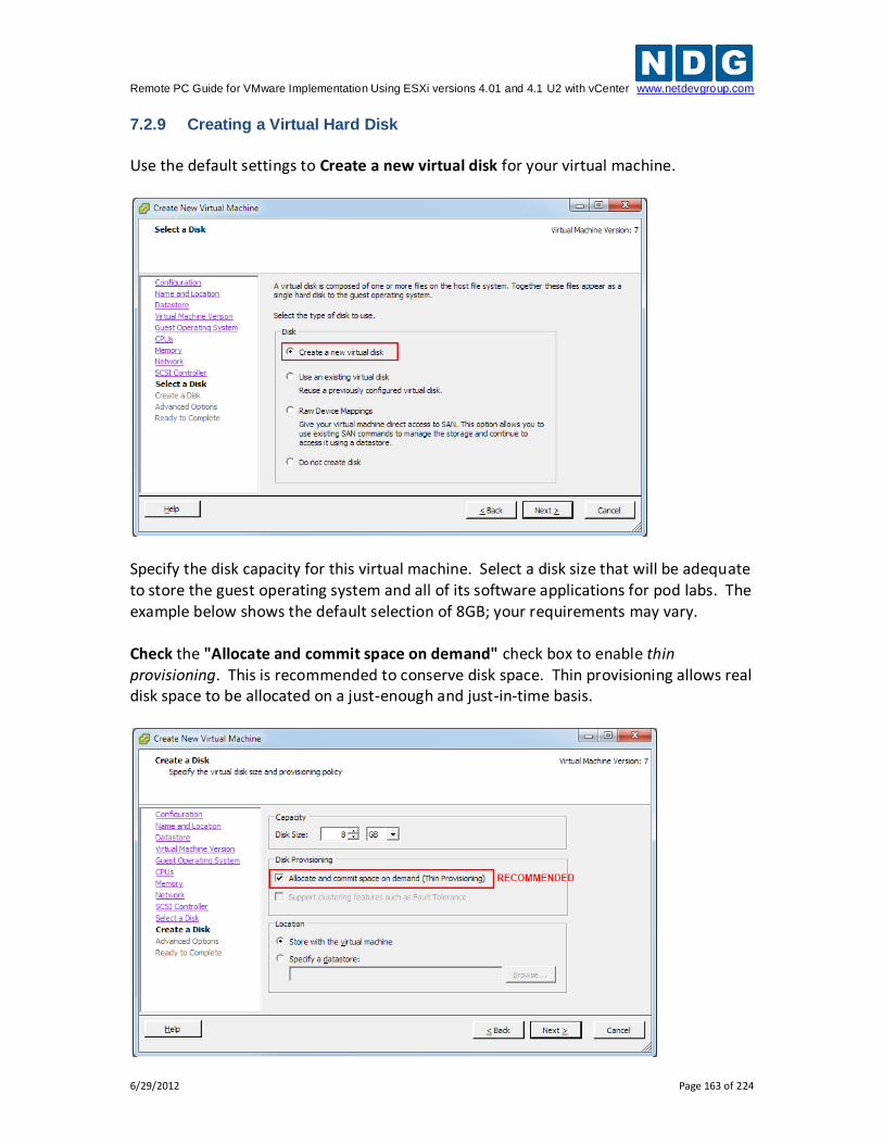
Remote PC Guide for VMware Implementation Using ESXi versions 4.01 and 4.1 U2 with vCenter www.netdevgroup.com
6/29/2012 Page 163 of 224
7.2.9 Creating a Virtual Hard Disk
Use the default settings to Create a new virtual disk for your virtual machine.
Specify the disk capacity for this virtual machine. Select a disk size that will be adequate to store the guest operating system and all of its software applications for pod labs. The example below shows the default selection of 8GB; your requirements may vary. Check the "Allocate and commit space on demand" check box to enable thin provisioning. This is recommended to conserve disk space. Thin provisioning allows real disk space to be allocated on a just-enough and just-in-time basis.
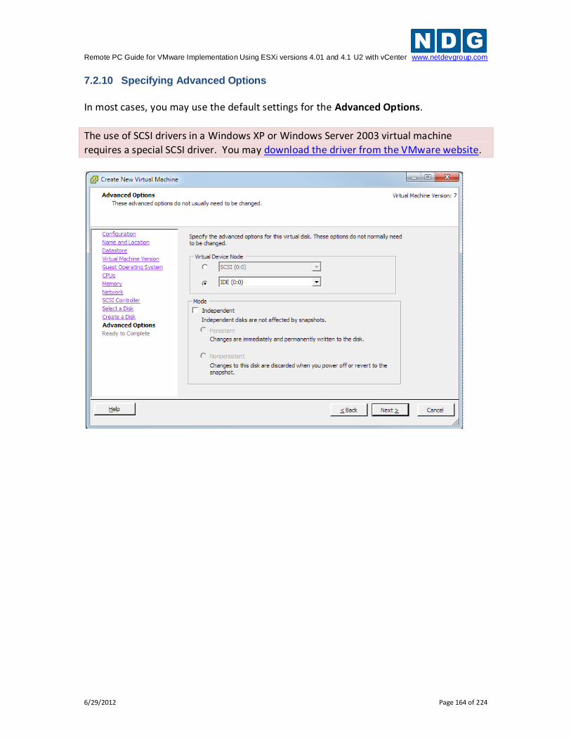
Remote PC Guide for VMware Implementation Using ESXi versions 4.01 and 4.1 U2 with vCenter www.netdevgroup.com
6/29/2012 Page 164 of 224
7.2.10 Specifying Advanced Options
In most cases, you may use the default settings for the Advanced Options.
The use of SCSI drivers in a Windows XP or Windows Server 2003 virtual machine
requires a special SCSI driver. You may download the driver from the VMware website.
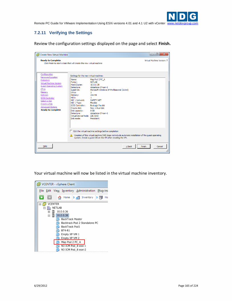
Remote PC Guide for VMware Implementation Using ESXi versions 4.01 and 4.1 U2 with vCenter www.netdevgroup.com
6/29/2012 Page 165 of 224
7.2.11 Verifying the Settings
Review the configuration settings displayed on the page and select Finish.
Your virtual machine will now be listed in the virtual machine inventory.
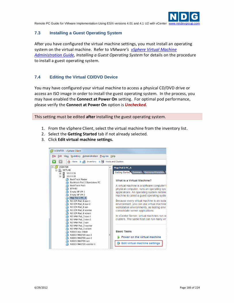
Remote PC Guide for VMware Implementation Using ESXi versions 4.01 and 4.1 U2 with vCenter www.netdevgroup.com
6/29/2012 Page 166 of 224
7.3 Installing a Guest Operating System
After you have configured the virtual machine settings, you must install an operating system on the virtual machine. Refer to VMware’s vSphere Virtual Machine Administration Guide, Installing a Guest Operating System for details on the procedure to install a guest operating system. 7.4 Editing the Virtual CD/DVD Device
You may have configured your virtual machine to access a physical CD/DVD drive or access an ISO image in order to install the guest operating system. In the process, you may have enabled the Connect at Power On setting. For optimal pod performance, please verify the Connect at Power On option is Unchecked.
This setting must be edited after installing the guest operating system.
1. From the vSphere Client, select the virtual machine from the inventory list. 2. Select the Getting Started tab if not already selected. 3. Click Edit virtual machine settings.
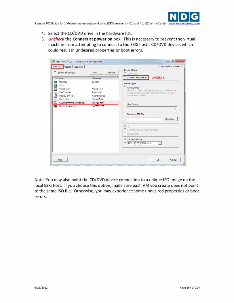
Remote PC Guide for VMware Implementation Using ESXi versions 4.01 and 4.1 U2 with vCenter www.netdevgroup.com
6/29/2012 Page 167 of 224
4. Select the CD/DVD drive in the hardware list. 5. Uncheck the Connect at power on box. This is necessary to prevent the virtual
machine from attempting to connect to the ESXi host’s CD/DVD device, which could result in undesired properties or boot errors.
Note: You may also point the CD/DVD device connection to a unique ISO image on the local ESXi host. If you choose this option, make sure each VM you create does not point to the same ISO file. Otherwise, you may experience some undesired properties or boot errors.
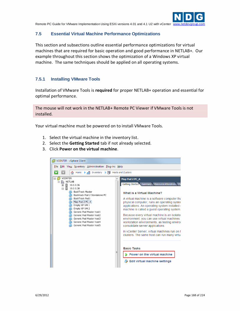
Remote PC Guide for VMware Implementation Using ESXi versions 4.01 and 4.1 U2 with vCenter www.netdevgroup.com
6/29/2012 Page 168 of 224
7.5 Essential Virtual Machine Performance Optimizations
This section and subsections outline essential performance optimizations for virtual machines that are required for basic operation and good performance in NETLAB+. Our example throughout this section shows the optimization of a Windows XP virtual machine. The same techniques should be applied on all operating systems. 7.5.1 Installing VMware Tools
Installation of VMware Tools is required for proper NETLAB+ operation and essential for optimal performance.
The mouse will not work in the NETLAB+ Remote PC Viewer if VMware Tools is not
installed.
Your virtual machine must be powered on to install VMware Tools.
1. Select the virtual machine in the inventory list. 2. Select the Getting Started tab if not already selected. 3. Click Power on the virtual machine.
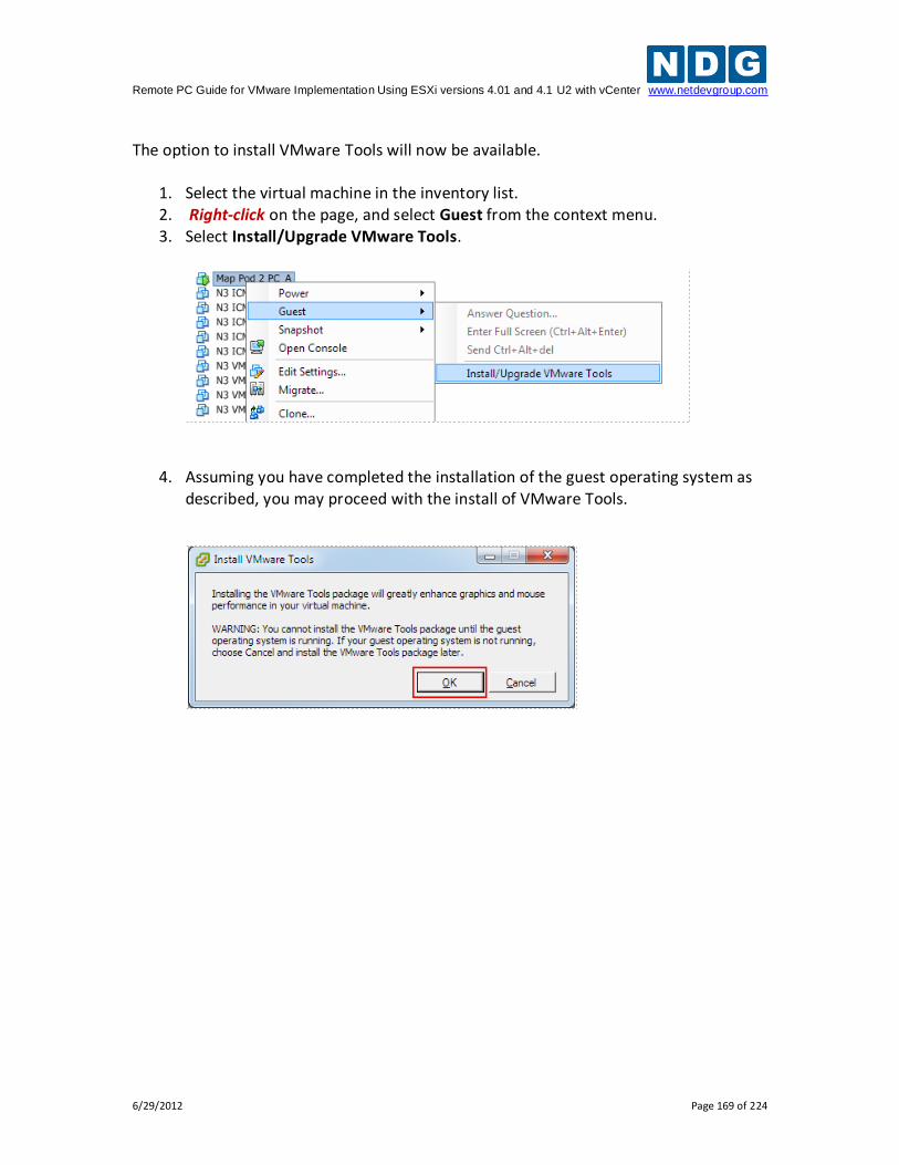
Remote PC Guide for VMware Implementation Using ESXi versions 4.01 and 4.1 U2 with vCenter www.netdevgroup.com
6/29/2012 Page 169 of 224
The option to install VMware Tools will now be available.
1. Select the virtual machine in the inventory list. 2. Right-click on the page, and select Guest from the context menu. 3. Select Install/Upgrade VMware Tools.
4. Assuming you have completed the installation of the guest operating system as described, you may proceed with the install of VMware Tools.
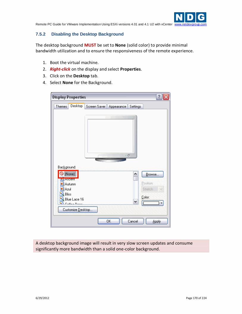
Remote PC Guide for VMware Implementation Using ESXi versions 4.01 and 4.1 U2 with vCenter www.netdevgroup.com
6/29/2012 Page 170 of 224
7.5.2 Disabling the Desktop Background
The desktop background MUST be set to None (solid color) to provide minimal bandwidth utilization and to ensure the responsiveness of the remote experience.
1. Boot the virtual machine.
2. Right-click on the display and select Properties.
3. Click on the Desktop tab.
4. Select None for the Background.
A desktop background image will result in very slow screen updates and consume significantly more bandwidth than a solid one-color background.
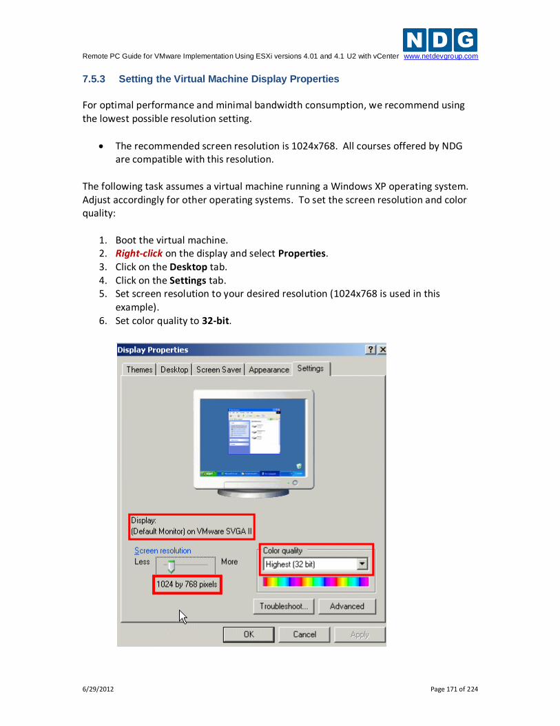
Remote PC Guide for VMware Implementation Using ESXi versions 4.01 and 4.1 U2 with vCenter www.netdevgroup.com
6/29/2012 Page 171 of 224
7.5.3 Setting the Virtual Machine Display Properties
For optimal performance and minimal bandwidth consumption, we recommend using the lowest possible resolution setting.
The recommended screen resolution is 1024x768. All courses offered by NDG are compatible with this resolution.
The following task assumes a virtual machine running a Windows XP operating system. Adjust accordingly for other operating systems. To set the screen resolution and color quality:
1. Boot the virtual machine. 2. Right-click on the display and select Properties. 3. Click on the Desktop tab. 4. Click on the Settings tab. 5. Set screen resolution to your desired resolution (1024x768 is used in this
example). 6. Set color quality to 32-bit.
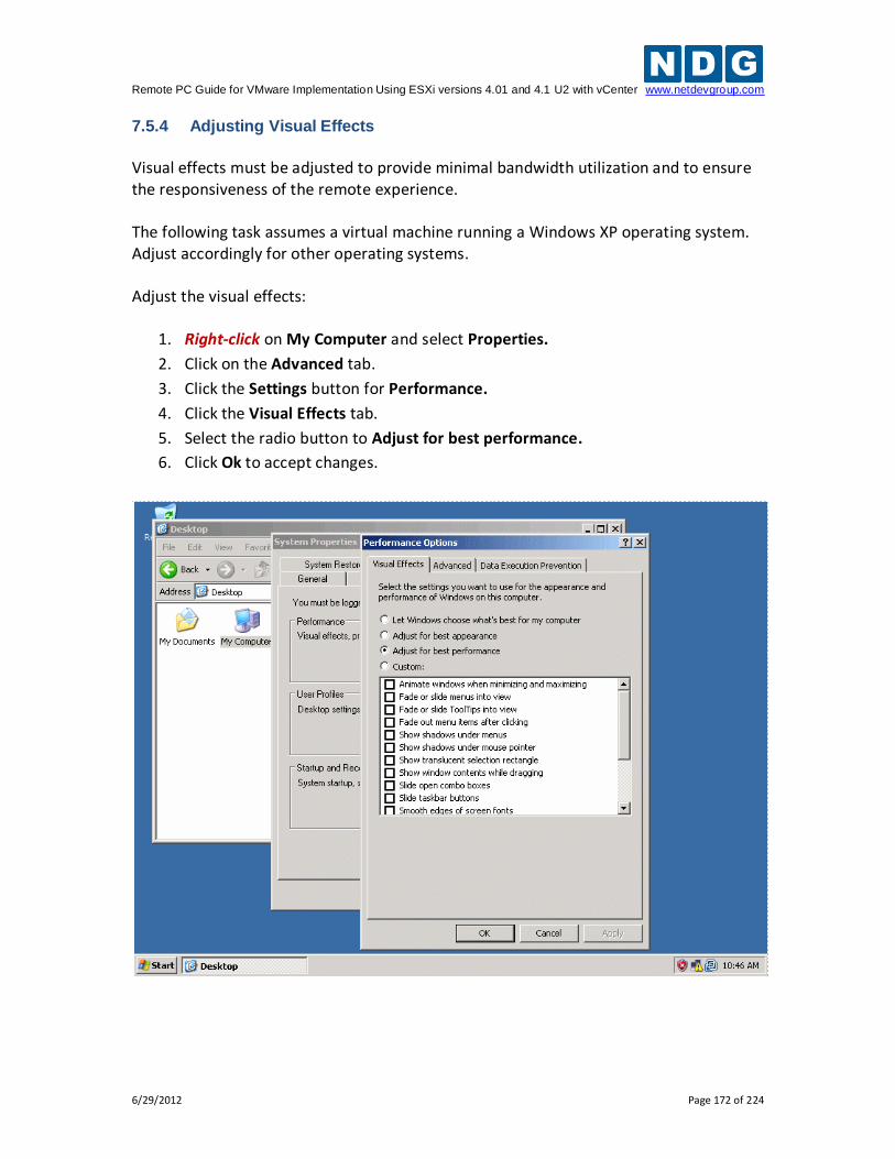
Remote PC Guide for VMware Implementation Using ESXi versions 4.01 and 4.1 U2 with vCenter www.netdevgroup.com
6/29/2012 Page 172 of 224
7.5.4 Adjusting Visual Effects
Visual effects must be adjusted to provide minimal bandwidth utilization and to ensure the responsiveness of the remote experience. The following task assumes a virtual machine running a Windows XP operating system. Adjust accordingly for other operating systems. Adjust the visual effects:
1. Right-click on My Computer and select Properties.
2. Click on the Advanced tab.
3. Click the Settings button for Performance.
4. Click the Visual Effects tab.
5. Select the radio button to Adjust for best performance.
6. Click Ok to accept changes.
Remote PC Guide for VMware Implementation Using ESXi versions 4.01 and 4.1 U2 with vCenter www.netdevgroup.com
6/29/2012 Page 173 of 224
7.6 Adding Software Applications
You may now add new software to your virtual machine as required by the lab exercises you plan to use on your pods. It may be helpful to temporarily bind the virtual network adapter to the outside campus network to load applications from the Internet or local file server.
The Secure+ network model does not provide outside connectivity. In this model, you will need to load from ISO files on the ESXi servers or from a file server VM on an inside network.
7.7 Virtual Machine Snapshots
A snapshot preserves the state and data of a virtual machine at a specific point in time.
State includes the virtual machine’s power state (powered‐on, powered‐off, suspended, etc).
Data includes all the files that make‐up the virtual machine, including configuration file, disks, memory, and other devices, such as virtual network interface cards.
The VMware vSphere client provides several operations for creating and managing snapshots and snapshot trees. These operations let you create snapshots, revert to any snapshot in the tree, and remove snapshots.
Large snapshot trees are not recommended for production virtual machines (see
Snapshot Best Practices, section 7.7.2 below).
7.7.1 How NETLAB+ Uses Snapshots
In NETLAB+, snapshots are used for two purposes. Virtual Machine Reset. A virtual machine can be optionally reset to a specific state at the beginning or end of a lab reservation, or when the user initiates the scrub action on the virtual machine or pod.
Linked Virtual Machines. A linked virtual machine shares a base virtual disk with a "master" virtual machine in an ongoing manner. This conserves disk space and allows multiple virtual machines to use the same software installation. A snapshot on the master virtual machine becomes the disk starting point for linked virtual machines that are derived from the master.
Remote PC Guide for VMware Implementation Using ESXi versions 4.01 and 4.1 U2 with vCenter www.netdevgroup.com
6/29/2012 Page 174 of 224
7.7.2 Snapshot Best Practices
Here are some best practices for using snapshots in the NETLAB+ environment and some common pitfalls to avoid. 1. Be sure to take a new snapshot each time you edit virtual machine settings or
install new applications on a virtual machine. Unsaved changes to a virtual machine are lost after reverting to snapshot. A revert to snapshot can occur manually when invoked from the vSphere client, or automatically by NETLAB+ (depending on your virtual machine inventory settings).
2. Take snapshots in a powered-off state. Snapshots taken in a powered-on or suspended state can reduce virtual machine boot time. However, this consumes significantly more disk space per VM than in a powered-off state. The disk space required can easily exceed one gigabyte since the virtual machine's memory state and/or swap files must also be preserved for powered-on and suspended states. Resuming from a powered-on or suspended state can also result in failed network connection states in some cases. To avoid these issues, gracefully power down the virtual machine before taking a snapshot.
3. Take only one snapshot per virtual machine for best performance. In academic environments, there is often an affinity for large snapshot trees since snapshots provide an intuitive way to return to a topic in a course syllabus. This is not recommended for production virtual machines where user performance is paramount. Large snapshot trees can degrade virtual machine performance. Each level in the snapshot tree creates a "delta disk" which must be accessed before data can be read from the "base disk" (where most files typically reside). We recommend only one snapshot per virtual machine, particularly when the virtual machine is used in a production pod, or for master virtual machines that are the basis for linked virtual machines.
4. Specify a unique name for every snapshot (if you must keep more than one snapshot on the same virtual machine). The vSphere client will allow you to create multiple snapshots with the same name. To avoid ambiguity during cloning operations, NETLAB+ requires that all snapshots on a single VM be named uniquely. NETLAB+ cloning operations may fail with the error E_VM_SNAPSHOT_NOT_UNIQUE when attempting to clone a virtual machine that has two or more snapshots with the same name. Duplicate snapshot names will not be an issue if you follow the best practice of one snapshot per virtual machine for best performance.
5. Snapshots used for linked clones must be thoroughly tested before cloning. Replacing a snapshot on the master (parent) virtual machine does not propagate changes to existing linked clones (as one might hope). Only new linked clones will pick up the changes from the new snapshot. Linked clones will be discussed in detail in the Cloning section.
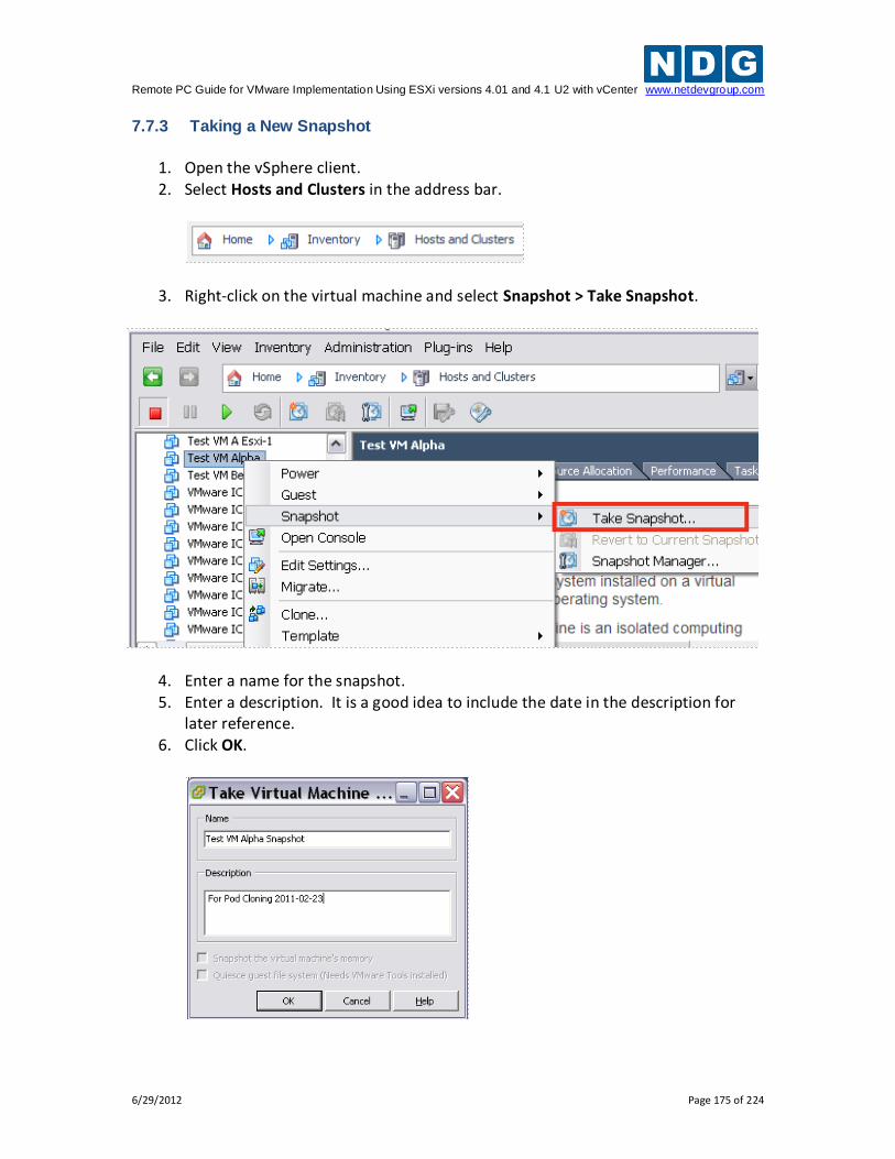
Remote PC Guide for VMware Implementation Using ESXi versions 4.01 and 4.1 U2 with vCenter www.netdevgroup.com
6/29/2012 Page 175 of 224
7.7.3 Taking a New Snapshot
1. Open the vSphere client. 2. Select Hosts and Clusters in the address bar.
3. Right-click on the virtual machine and select Snapshot > Take Snapshot.
4. Enter a name for the snapshot. 5. Enter a description. It is a good idea to include the date in the description for
later reference. 6. Click OK.
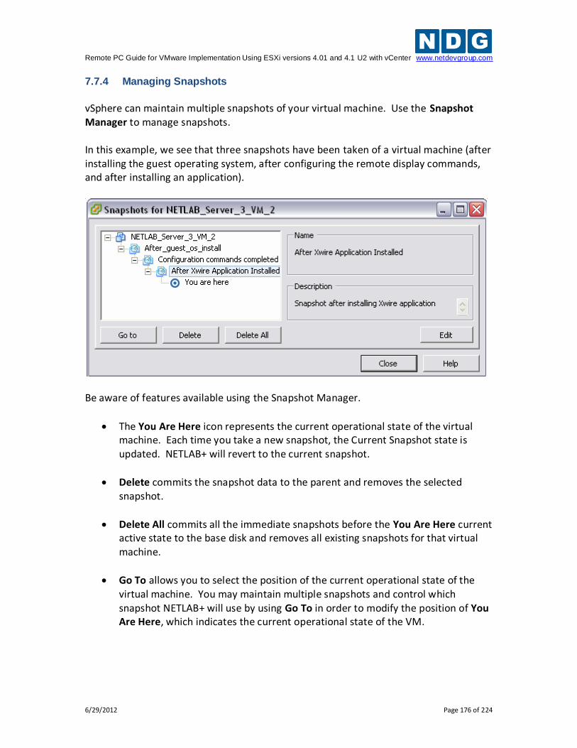
Remote PC Guide for VMware Implementation Using ESXi versions 4.01 and 4.1 U2 with vCenter www.netdevgroup.com
6/29/2012 Page 176 of 224
7.7.4 Managing Snapshots
vSphere can maintain multiple snapshots of your virtual machine. Use the Snapshot Manager to manage snapshots. In this example, we see that three snapshots have been taken of a virtual machine (after installing the guest operating system, after configuring the remote display commands, and after installing an application).
Be aware of features available using the Snapshot Manager.
The You Are Here icon represents the current operational state of the virtual machine. Each time you take a new snapshot, the Current Snapshot state is updated. NETLAB+ will revert to the current snapshot.
Delete commits the snapshot data to the parent and removes the selected snapshot.
Delete All commits all the immediate snapshots before the You Are Here current active state to the base disk and removes all existing snapshots for that virtual machine.
Go To allows you to select the position of the current operational state of the virtual machine. You may maintain multiple snapshots and control which snapshot NETLAB+ will use by using Go To in order to modify the position of You Are Here, which indicates the current operational state of the VM.
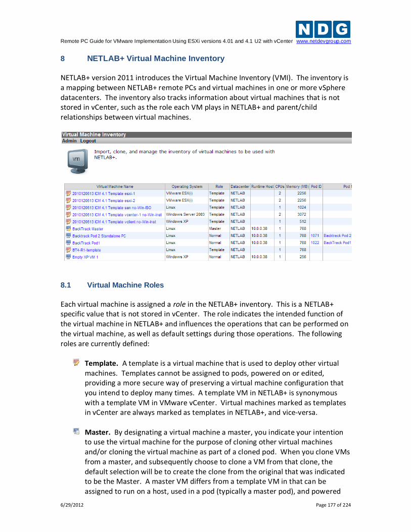
Remote PC Guide for VMware Implementation Using ESXi versions 4.01 and 4.1 U2 with vCenter www.netdevgroup.com
6/29/2012 Page 177 of 224
8 NETLAB+ Virtual Machine Inventory NETLAB+ version 2011 introduces the Virtual Machine Inventory (VMI). The inventory is a mapping between NETLAB+ remote PCs and virtual machines in one or more vSphere datacenters. The inventory also tracks information about virtual machines that is not stored in vCenter, such as the role each VM plays in NETLAB+ and parent/child relationships between virtual machines.
8.1 Virtual Machine Roles
Each virtual machine is assigned a role in the NETLAB+ inventory. This is a NETLAB+ specific value that is not stored in vCenter. The role indicates the intended function of the virtual machine in NETLAB+ and influences the operations that can be performed on the virtual machine, as well as default settings during those operations. The following roles are currently defined:
Template. A template is a virtual machine that is used to deploy other virtual machines. Templates cannot be assigned to pods, powered on or edited, providing a more secure way of preserving a virtual machine configuration that you intend to deploy many times. A template VM in NETLAB+ is synonymous with a template VM in VMware vCenter. Virtual machines marked as templates in vCenter are always marked as templates in NETLAB+, and vice-versa.
Master. By designating a virtual machine a master, you indicate your intention to use the virtual machine for the purpose of cloning other virtual machines and/or cloning the virtual machine as part of a cloned pod. When you clone VMs from a master, and subsequently choose to clone a VM from that clone, the default selection will be to create the clone from the original that was indicated to be the Master. A master VM differs from a template VM in that can be assigned to run on a host, used in a pod (typically a master pod), and powered
Remote PC Guide for VMware Implementation Using ESXi versions 4.01 and 4.1 U2 with vCenter www.netdevgroup.com
6/29/2012 Page 178 of 224
on for the purpose of adding and configuring new software. Once the virtual machine has all the required software components and thoroughly tested, a golden master snapshot is taken and becomes the basis for full or linked clones (discussed later).
Normal. A normal VM is a virtual machine that will be assigned to a production
pod. A normal VM may be configured to revert to a snapshot at the beginning and end of a lab reservation, or when the user explicitly invokes the scrub action on the VM or the entire pod. A normal VM is an ideal choice for pods that should always start in the same state, such as VMs in Cisco Netacad pods.
Persistent. A persistent VM is assigned to a production pod, with the additional
characteristic that its state will be retained from one reservation to the next. A persistent VM never reverts to a snapshot. This type of VM is appropriate when the user assigned to the pod is working on a curriculum that carries the result of each lab assignment progressively. An example scenario would be a course where the student performs “Lab One” and then on a subsequent reservation performs “Lab Two”, with the pod in the state it was in at the end of “Lab One”.
8.2 How Virtual Machines Become Part of the NETLAB+ Inventory
Virtual machines must first reside in the NETLAB+ Virtual Machine Inventory before they can be assigned to pods and function as NETLAB+ remote PCs. There are three ways virtual machines can become part of the NETLAB+ inventory:
Import. NETLAB+ communicates with vCenter and scans the selected datacenter to identify existing VMs that are available to be added to the NETLAB+ virtual machine inventory. The import function is used to import virtual machines that were created outside of NETLAB+ (i.e. from the vSphere Client or VMware Converter).
Clone VM. NETLAB+ communicates with vCenter and makes a copy of a virtual machine that already exists in the NETLAB+ inventory. When a virtual machine is cloned from the NETLAB+ inventory, the new virtual machine is added to both the NETLAB+ inventory and vCenter in one operation. NETLAB+ also supports linked clones (virtual machines that share disk content with another parent virtual machine).
Clone Pod. If a pod contains only virtual machines, NETLAB+ can clone the entire pod in one operation. Each virtual machine in the source pod is cloned and added to both the NETLAB+ inventory and vCenter in one operation.
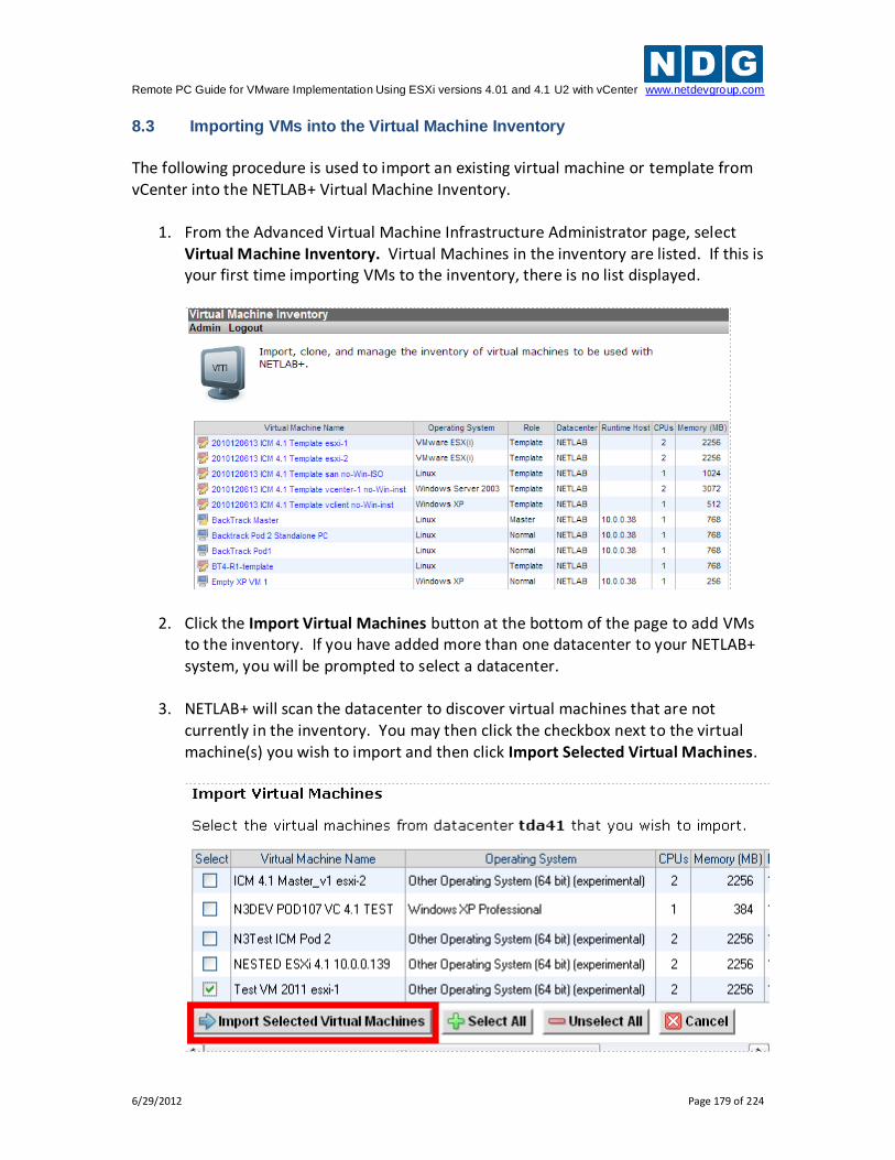
Remote PC Guide for VMware Implementation Using ESXi versions 4.01 and 4.1 U2 with vCenter www.netdevgroup.com
6/29/2012 Page 179 of 224
8.3 Importing VMs into the Virtual Machine Inventory
The following procedure is used to import an existing virtual machine or template from vCenter into the NETLAB+ Virtual Machine Inventory.
1. From the Advanced Virtual Machine Infrastructure Administrator page, select Virtual Machine Inventory. Virtual Machines in the inventory are listed. If this is your first time importing VMs to the inventory, there is no list displayed.
2. Click the Import Virtual Machines button at the bottom of the page to add VMs to the inventory. If you have added more than one datacenter to your NETLAB+ system, you will be prompted to select a datacenter.
3. NETLAB+ will scan the datacenter to discover virtual machines that are not
currently in the inventory. You may then click the checkbox next to the virtual machine(s) you wish to import and then click Import Selected Virtual Machines.
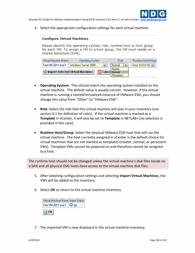
Remote PC Guide for VMware Implementation Using ESXi versions 4.01 and 4.1 U2 with vCenter www.netdevgroup.com
6/29/2012 Page 180 of 224
4. Select the appropriate configuration settings for each virtual machine.
Operating System: This should match the operating system installed on the virtual machine. The default value is usually correct. However, if the virtual machine is running a nested/virtualized instance of VMware ESXi, you should change this value from "Other" to "VMware ESXi".
Role: Select the role that this virtual machine will play in your inventory (see section 8.1 for definition of roles). If the virtual machine is marked as a Template in vCenter, it will also be set to Template in NETLAB+ (no selection is provided in this case).
Runtime Host/Group: Select the physical VMware ESXi host that will run the virtual machine. The host currently assigned in vCenter is the default choice for virtual machines that are not marked as templates (master, normal, or persistent VMs). Template VMs cannot be powered on and therefore cannot be assigned to a host.
The runtime host should not be changed unless the virtual machine's disk files reside on
a SAN and all physical ESXi hosts have access to the virtual machine disk files.
5. After selecting configuration settings and selecting Import Virtual Machines, the
VMs will be added to the inventory.
6. Select OK to return to the virtual machine inventory.
7. The imported VM is now displayed in the virtual machine inventory.
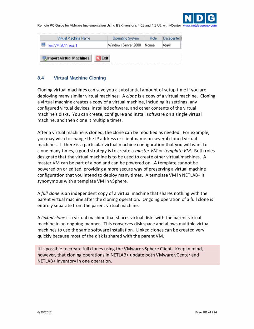
Remote PC Guide for VMware Implementation Using ESXi versions 4.01 and 4.1 U2 with vCenter www.netdevgroup.com
6/29/2012 Page 181 of 224
8.4 Virtual Machine Cloning
Cloning virtual machines can save you a substantial amount of setup time if you are deploying many similar virtual machines. A clone is a copy of a virtual machine. Cloning a virtual machine creates a copy of a virtual machine, including its settings, any configured virtual devices, installed software, and other contents of the virtual machine's disks. You can create, configure and install software on a single virtual machine, and then clone it multiple times. After a virtual machine is cloned, the clone can be modified as needed. For example, you may wish to change the IP address or client name on several cloned virtual machines. If there is a particular virtual machine configuration that you will want to clone many times, a good strategy is to create a master VM or template VM. Both roles designate that the virtual machine is to be used to create other virtual machines. A master VM can be part of a pod and can be powered on. A template cannot be powered on or edited, providing a more secure way of preserving a virtual machine configuration that you intend to deploy many times. A template VM in NETLAB+ is synonymous with a template VM in vSphere.
A full clone is an independent copy of a virtual machine that shares nothing with the parent virtual machine after the cloning operation. Ongoing operation of a full clone is entirely separate from the parent virtual machine. A linked clone is a virtual machine that shares virtual disks with the parent virtual machine in an ongoing manner. This conserves disk space and allows multiple virtual machines to use the same software installation. Linked clones can be created very quickly because most of the disk is shared with the parent VM.
It is possible to create full clones using the VMware vSphere Client. Keep in mind, however, that cloning operations in NETLAB+ update both VMware vCenter and NETLAB+ inventory in one operation.
Remote PC Guide for VMware Implementation Using ESXi versions 4.01 and 4.1 U2 with vCenter www.netdevgroup.com
6/29/2012 Page 182 of 224
8.4.1 Golden Masters and Golden Snapshots
Master virtual machines and templates should be thoroughly tested before making production clones (full or linked). A master virtual machine (or template) that has been tested and deemed to be production quality is called a golden master. Linked clones also require a pristine snapshot that becomes the base disk for linked clones. This snapshot is called a golden snapshot. Keep in mind the following important rules about golden snapshots.
1. Updates to the golden snapshot only affect NEW clones (full or linked).
2. Updates to the golden snapshot do not affect EXISTING clones (full or linked). Since snapshots operate on disk sectors and not individual files, this would lead to disk corruption and is prevented by vSphere.
It is inevitable that at some point your master VMs will need to be updated, either in response to a defect or to install new files. When this need arises, you must decide whether to update existing clones, or create them over again. Since linked clones can be made very quickly (including pod cloning), it may be easier to simply re-clone from the updated master VMs. Should you decide to update existing clones, be sure to create a new snapshot on each clone if the clone is a normal VM that reverts to snapshot. 8.4.2 Using NETLAB+ to Clone a Single Virtual Machine
NETLAB+ provides a convenient way to clone virtual machines. In order to clone virtual machines within NETLAB+, you must first create a source virtual machine or template (see section 7), to be used as the source for the clone. The source virtual machine must also be registered in the NETLAB+ inventory.
1. To clone a virtual machine, select the source virtual machine to be cloned in the NETLAB+ Virtual Machine Inventory. In this example we have a selected a virtual machine that has been designated a master. Notice also that since this virtual machine has been assigned to a pod, the pod name and link to the pod management page are available.
2. Begin the cloning process by selecting the Clone button.
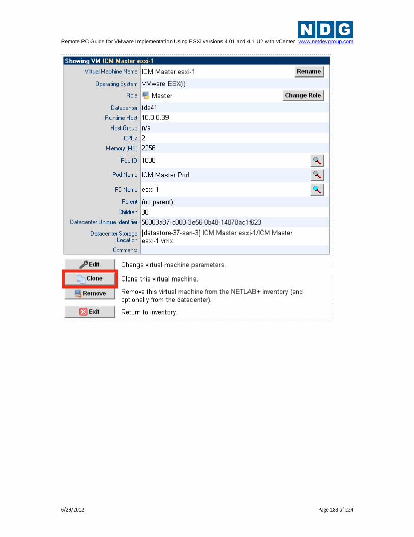
Remote PC Guide for VMware Implementation Using ESXi versions 4.01 and 4.1 U2 with vCenter www.netdevgroup.com
6/29/2012 Page 183 of 224
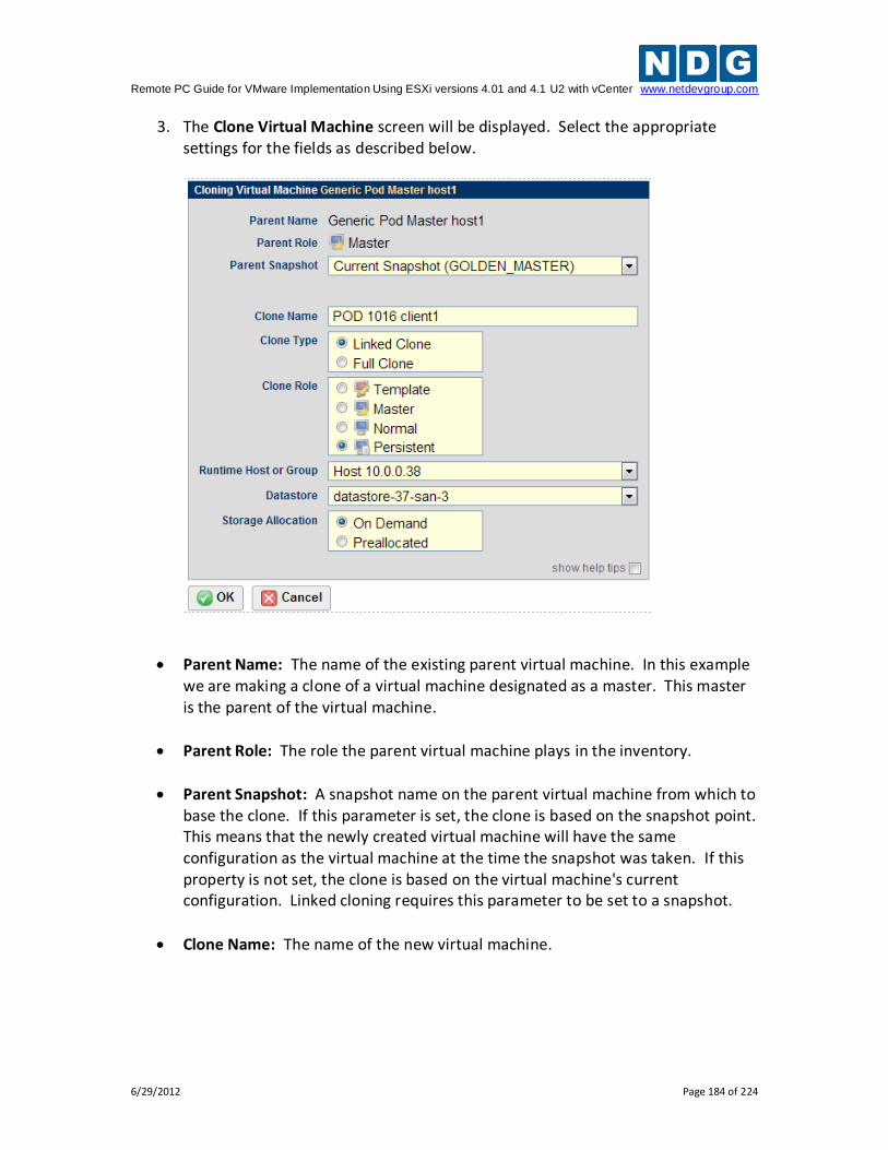
Remote PC Guide for VMware Implementation Using ESXi versions 4.01 and 4.1 U2 with vCenter www.netdevgroup.com
6/29/2012 Page 184 of 224
3. The Clone Virtual Machine screen will be displayed. Select the appropriate settings for the fields as described below.
Parent Name: The name of the existing parent virtual machine. In this example we are making a clone of a virtual machine designated as a master. This master is the parent of the virtual machine.
Parent Role: The role the parent virtual machine plays in the inventory.
Parent Snapshot: A snapshot name on the parent virtual machine from which to base the clone. If this parameter is set, the clone is based on the snapshot point. This means that the newly created virtual machine will have the same configuration as the virtual machine at the time the snapshot was taken. If this property is not set, the clone is based on the virtual machine's current configuration. Linked cloning requires this parameter to be set to a snapshot.
Clone Name: The name of the new virtual machine.
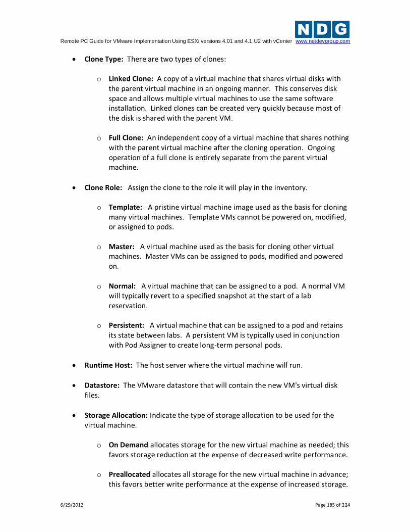
Remote PC Guide for VMware Implementation Using ESXi versions 4.01 and 4.1 U2 with vCenter www.netdevgroup.com
6/29/2012 Page 185 of 224
Clone Type: There are two types of clones:
o Linked Clone: A copy of a virtual machine that shares virtual disks with the parent virtual machine in an ongoing manner. This conserves disk space and allows multiple virtual machines to use the same software installation. Linked clones can be created very quickly because most of the disk is shared with the parent VM.
o Full Clone: An independent copy of a virtual machine that shares nothing with the parent virtual machine after the cloning operation. Ongoing operation of a full clone is entirely separate from the parent virtual machine.
Clone Role: Assign the clone to the role it will play in the inventory.
o Template: A pristine virtual machine image used as the basis for cloning many virtual machines. Template VMs cannot be powered on, modified, or assigned to pods.
o Master: A virtual machine used as the basis for cloning other virtual
machines. Master VMs can be assigned to pods, modified and powered on.
o Normal: A virtual machine that can be assigned to a pod. A normal VM
will typically revert to a specified snapshot at the start of a lab reservation.
o Persistent: A virtual machine that can be assigned to a pod and retains
its state between labs. A persistent VM is typically used in conjunction with Pod Assigner to create long-term personal pods.
Runtime Host: The host server where the virtual machine will run.
Datastore: The VMware datastore that will contain the new VM's virtual disk files.
Storage Allocation: Indicate the type of storage allocation to be used for the virtual machine.
o On Demand allocates storage for the new virtual machine as needed; this
favors storage reduction at the expense of decreased write performance.
o Preallocated allocates all storage for the new virtual machine in advance; this favors better write performance at the expense of increased storage.
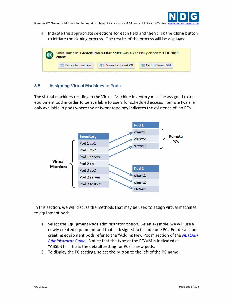
Remote PC Guide for VMware Implementation Using ESXi versions 4.01 and 4.1 U2 with vCenter www.netdevgroup.com
6/29/2012 Page 186 of 224
4. Indicate the appropriate selections for each field and then click the Clone button to initiate the cloning process. The results of the process will be displayed.
8.5 Assigning Virtual Machines to Pods
The virtual machines residing in the Virtual Machine Inventory must be assigned to an equipment pod in order to be available to users for scheduled access. Remote PCs are only available in pods where the network topology indicates the existence of lab PCs.
In this section, we will discuss the methods that may be used to assign virtual machines to equipment pods.
1. Select the Equipment Pods administrator option. As an example, we will use a newly created equipment pod that is designed to include one PC. For details on creating equipment pods refer to the “Adding New Pods” section of the NETLAB+ Administrator Guide Notice that the type of the PC/VM is indicated as “ABSENT”. This is the default setting for PCs in new pods.
2. To display the PC settings, select the button to the left of the PC name.
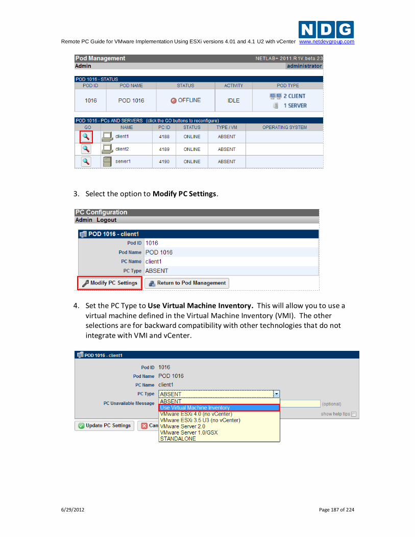
Remote PC Guide for VMware Implementation Using ESXi versions 4.01 and 4.1 U2 with vCenter www.netdevgroup.com
6/29/2012 Page 187 of 224
3. Select the option to Modify PC Settings.
4. Set the PC Type to Use Virtual Machine Inventory. This will allow you to use a virtual machine defined in the Virtual Machine Inventory (VMI). The other selections are for backward compatibility with other technologies that do not integrate with VMI and vCenter.
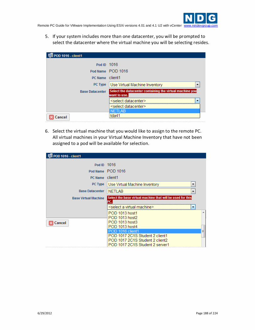
Remote PC Guide for VMware Implementation Using ESXi versions 4.01 and 4.1 U2 with vCenter www.netdevgroup.com
6/29/2012 Page 188 of 224
5. If your system includes more than one datacenter, you will be prompted to select the datacenter where the virtual machine you will be selecting resides.
6. Select the virtual machine that you would like to assign to the remote PC. All virtual machines in your Virtual Machine Inventory that have not been assigned to a pod will be available for selection.
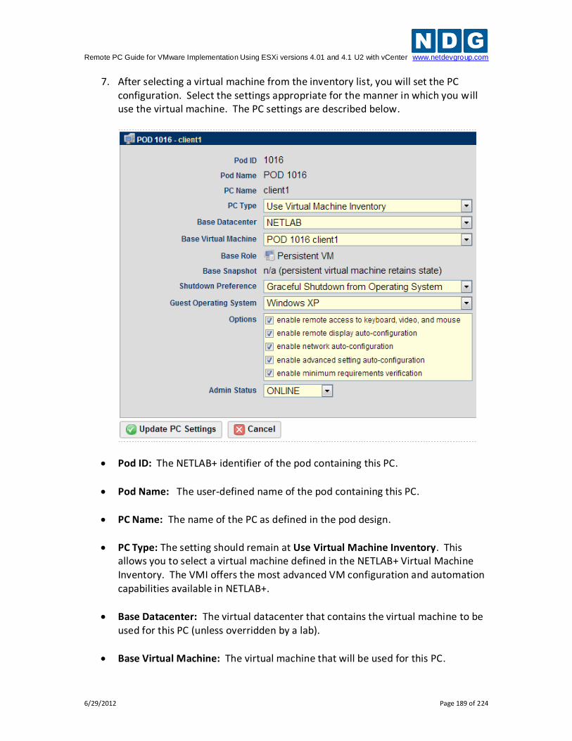
Remote PC Guide for VMware Implementation Using ESXi versions 4.01 and 4.1 U2 with vCenter www.netdevgroup.com
6/29/2012 Page 189 of 224
7. After selecting a virtual machine from the inventory list, you will set the PC configuration. Select the settings appropriate for the manner in which you will use the virtual machine. The PC settings are described below.
Pod ID: The NETLAB+ identifier of the pod containing this PC.
Pod Name: The user-defined name of the pod containing this PC.
PC Name: The name of the PC as defined in the pod design.
PC Type: The setting should remain at Use Virtual Machine Inventory. This allows you to select a virtual machine defined in the NETLAB+ Virtual Machine Inventory. The VMI offers the most advanced VM configuration and automation capabilities available in NETLAB+.
Base Datacenter: The virtual datacenter that contains the virtual machine to be used for this PC (unless overridden by a lab).
Base Virtual Machine: The virtual machine that will be used for this PC.
Remote PC Guide for VMware Implementation Using ESXi versions 4.01 and 4.1 U2 with vCenter www.netdevgroup.com
6/29/2012 Page 190 of 224
Base Role: The pre-assigned role that the base virtual machine plays in the inventory.
Base Snapshot: The snapshot that will be used to revert the base virtual machine to a clean state during pod initialization, user initiated scrub action, and at the end of a lab reservation. This setting does not apply to persistent VMs because that always retain state.
Shutdown Preference: Select the preferred shutdown sequence if the virtual machine is still powered on at the end of a lab reservation. If a base snapshot is configured, it is reverted first. If the virtual machine is still powered on after reverting to the specified snapshot, the preferred shutdown sequence is executed. Otherwise, the final power state will be the same as the snapshot state.
o Graceful Shutdown from Operating System: Perform an orderly shutdown from the operating system if possible (i.e. VMware Tools is supported and installed on the VM). This is best setting in most situations. If an orderly shutdown is not possible, the virtual machine is powered off.
o Power Off: Powers off the virtual machine. Does not perform an orderly shutdown.
This option is not recommended for persistent virtual machines as this
may lead to disk corruption.
o Suspend Virtual Machine: Suspend the virtual machine in its current
state. When powered on, it will resume in the same state without booting.
This option will cause virtual machines memory and page files to be retained on disk. Significant disk space per VM may be required to
support this option. Network connection state is not preserved.
o Keep Running: The virtual machine is left in the powered on state.
This is rarely desirable since the VM will continue to consume host CPU and memory resources.
Remote PC Guide for VMware Implementation Using ESXi versions 4.01 and 4.1 U2 with vCenter www.netdevgroup.com
6/29/2012 Page 191 of 224
Guest Operating System: The operating system running on this virtual machine.
Options: Enable or disable automated features.
o Enable remote access to keyboard, video, and mouse: if enabled, NETLAB+ will allow the virtual machine to be accessed using a built-in remote PC viewers. Keep this option enabled unless you do not want users to access the VM; for example, a special server in the pod that should not be configured by the user.
o Enable remote display auto-configuration: if enabled, NETLAB+ will automatically configure remote display parameters on the VM after a power on or revert to snapshot operation. This option allows VMs to be cloned without manual customization of the remote display settings. Therefore, we recommend you enable this setting and be happy about it.
o Enable network auto-configuration: if enabled, NETLAB+ will automatically bind the virtual machine's network adapters to the correct port group. This option allows VMs to be cloned without manual customization of networking bindings. This option is ignored if the pod type does not support automatic networking. If this setting is disabled and/or the pod type does not support automatic networking, then the virtual machine network adapters must be manually bound to the correct port group(s) using the vSphere client.
o Enable advanced setting auto-configuration: if enabled, NETLAB+ will automatically program advanced virtual machine settings that may be required for a particular pod type. For example, nested VM support for the VMware IT Academy program. It is usually safe to enable this option. It will be ignored if the pod type does not require advanced settings.
o Enable minimum requirements verification: if enabled, NETLAB+ will verify that the current settings of the virtual machine meet or exceed any minimum requirements established for the remote PC to which it is assigned. It is usually safe to enable this option. The setting will be ignored if the pod type does not specify a set of minimum requirements for the remote PC.
Admin Status: Set administrative status to ONLINE to enable this PC. You can temporarily disable this PC by setting the administrative status to OFFLINE.
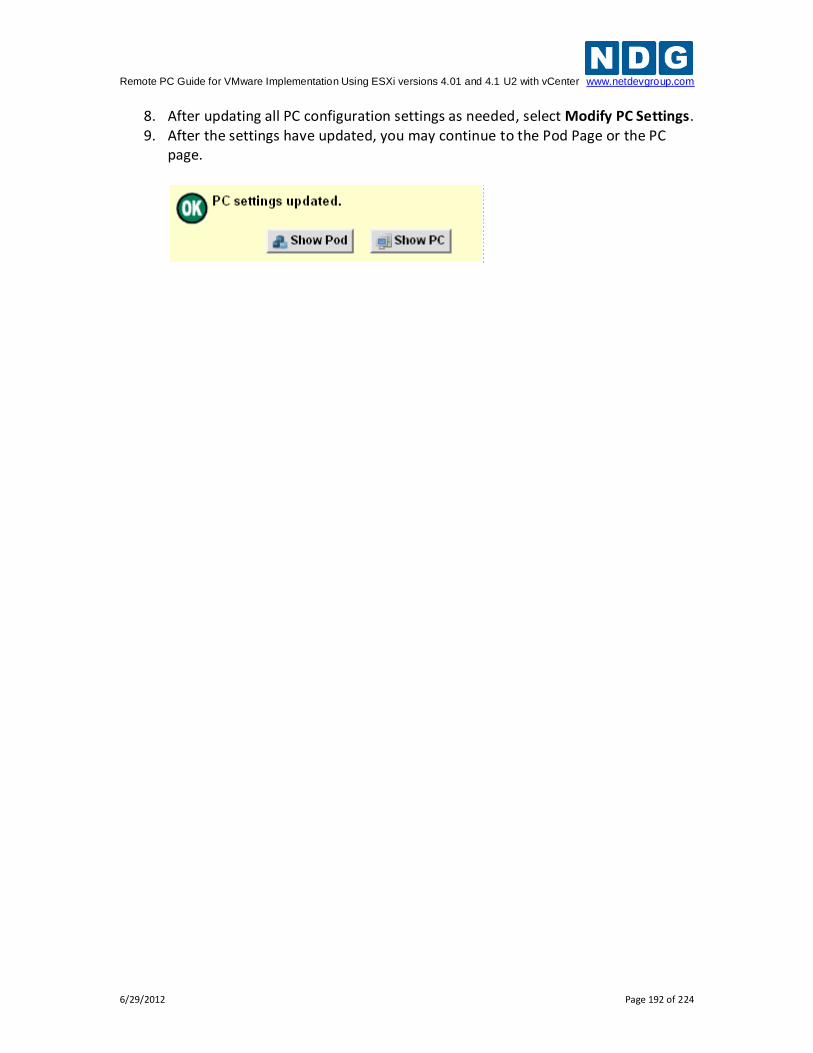
Remote PC Guide for VMware Implementation Using ESXi versions 4.01 and 4.1 U2 with vCenter www.netdevgroup.com
6/29/2012 Page 192 of 224
8. After updating all PC configuration settings as needed, select Modify PC Settings. 9. After the settings have updated, you may continue to the Pod Page or the PC
page.
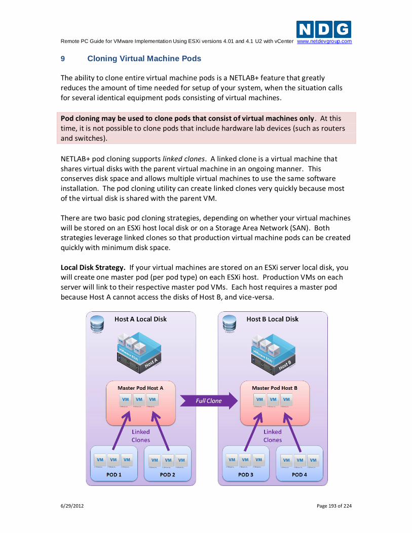
Remote PC Guide for VMware Implementation Using ESXi versions 4.01 and 4.1 U2 with vCenter www.netdevgroup.com
6/29/2012 Page 193 of 224
9 Cloning Virtual Machine Pods The ability to clone entire virtual machine pods is a NETLAB+ feature that greatly reduces the amount of time needed for setup of your system, when the situation calls for several identical equipment pods consisting of virtual machines.
Pod cloning may be used to clone pods that consist of virtual machines only. At this time, it is not possible to clone pods that include hardware lab devices (such as routers and switches).
NETLAB+ pod cloning supports linked clones. A linked clone is a virtual machine that shares virtual disks with the parent virtual machine in an ongoing manner. This conserves disk space and allows multiple virtual machines to use the same software installation. The pod cloning utility can create linked clones very quickly because most of the virtual disk is shared with the parent VM. There are two basic pod cloning strategies, depending on whether your virtual machines will be stored on an ESXi host local disk or on a Storage Area Network (SAN). Both strategies leverage linked clones so that production virtual machine pods can be created quickly with minimum disk space. Local Disk Strategy. If your virtual machines are stored on an ESXi server local disk, you will create one master pod (per pod type) on each ESXi host. Production VMs on each server will link to their respective master pod VMs. Each host requires a master pod because Host A cannot access the disks of Host B, and vice-versa.
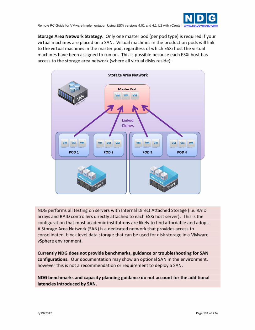
Remote PC Guide for VMware Implementation Using ESXi versions 4.01 and 4.1 U2 with vCenter www.netdevgroup.com
6/29/2012 Page 194 of 224
Storage Area Network Strategy. Only one master pod (per pod type) is required if your virtual machines are placed on a SAN. Virtual machines in the production pods will link to the virtual machines in the master pod, regardless of which ESXi host the virtual machines have been assigned to run on. This is possible because each ESXi host has access to the storage area network (where all virtual disks reside).
NDG performs all testing on servers with Internal Direct Attached Storage (i.e. RAID arrays and RAID controllers directly attached to each ESXi host server). This is the configuration that most academic institutions are likely to find affordable and adopt. A Storage Area Network (SAN) is a dedicated network that provides access to consolidated, block level data storage that can be used for disk storage in a VMware vSphere environment. Currently NDG does not provide benchmarks, guidance or troubleshooting for SAN configurations. Our documentation may show an optional SAN in the environment, however this is not a recommendation or requirement to deploy a SAN. NDG benchmarks and capacity planning guidance do not account for the additional
latencies introduced by SAN.
Remote PC Guide for VMware Implementation Using ESXi versions 4.01 and 4.1 U2 with vCenter www.netdevgroup.com
6/29/2012 Page 195 of 224
9.1 Golden Masters and Golden Snapshots
Virtual machines in a master pod should be thoroughly tested before pod cloning takes place (full or linked). A master virtual machine that has been tested and deemed to be production quality is called a golden master. Linked clones also require a pristine snapshot that becomes the base disk for linked clones. This snapshot is called a golden snapshot. Keep in mind the following important rules about golden snapshots.
1. Updates to the golden snapshot only affect NEW clones (full or linked).
2. Updates to the golden snapshot do not affect EXISTING clones (full or linked). Since snapshots operate on disk sectors and not individual files, this would lead to disk corruption and is prevented by vSphere.
At some point, the VMs in your master pod will need to be updated, either in response to a defect or to install new files. When this need arises, you must decide whether to update existing cloned pods, or create them over again. Since linked clones can be created very quickly, it may be easier to simply re-clone the pod rather than touch every existing clone pod. 9.2 Creating a Master Pod
The first step in the pod cloning process is to create a master pod. At this time, the pod type must contain only virtual machines if it is to be cloned using the pod cloning utility. The following steps are used to create a master pod.
1. Create a new pod in NETLAB+ of the desired type. All of the pod VMs will initially be set to ABSENT.
2. Using the techniques outlined in section 7, build some virtual machines that will map to each remote PC position for the pod type you are targeting.
a. Each virtual machine in the master pod should have its role set to master. The role can be set when importing a virtual machine or cloning a virtual machine. You can also change the role of an existing virtual machine to master.
b. Whether you are storing VMs on an ESXi local disk or SAN, you should assign the master to run on one of the ESXi hosts so software can be installed on the VMs and the pod tested as a single functional unit.
3. Assign your master virtual machines to the new master pod (section 8.5). 4. You may wish to use Pod Assigner at this point to prevent others from
scheduling the pod. You may assign the pod to an instructor account for this purpose.
Remote PC Guide for VMware Implementation Using ESXi versions 4.01 and 4.1 U2 with vCenter www.netdevgroup.com
6/29/2012 Page 196 of 224
5. Many NDG virtual pods support automatic networking. On the other hand, if you are using a custom built pod or other pod that does not have automatic networking support, you should make sure the virtual machines network adapters are bound to the correct networks at this time.
6. Bring the pod online so that it can be tested. 7. Test the master pod.
a. Login to an instructor account (use the same account used with pod assigner in step 3 if applicable).
b. Scheduled lab reservation in NETLAB+ and test the pod thoroughly including testing all the virtual machines to assure proper configuration.
8. Linked clones in a master pod require a pristine snapshot that becomes the base disk for your production linked clones. This snapshot is called a golden snapshot. Once you are very confident that the virtual machines in the master pod are free of defects, it is time to create a golden snapshot.
a. In most cases, you will want to power down every virtual machine before taking the golden snapshot, for reasons explained in section 7.7.4. You can do this from the NETLAB+ action tab or from the vSphere client.
b. Take a snapshot on each master VM using a name such as GOLDEN_SNAPSHOT. Currently, you must take snapshots using the vSphere client.
Once each virtual machine in the master pod has a golden snapshot, linked clones are possible.
9.3 Cloning a Virtual Machine Pod Using Linked Clones
In this section you will learn how clone a master virtual machine pod using linked clones. Let’s suppose that the master pod is called pod MP1 and we want to create similar cloned pods called CP1, CP2, CP3, etc. The first time you clone the master MP1 to create cloned pod CP1, you will need to specify some parameters for each virtual machine in CP1. NETLAB+ will keep track of the parameters used to clone CP1. You can then instruct NETLAB+ to "create a CP2 pod like CP1" by cloning from CP1 instead of MP1. In our first example, we will make clone the master pod for the first time (MP1 to CP1). The 3 virtual machines are master VMs with a golden snapshot. Recall that a golden snapshot on master VM is required to create linked clones.
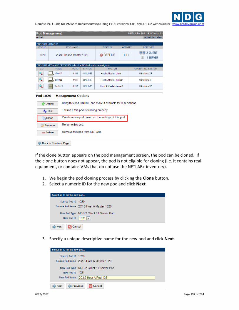
Remote PC Guide for VMware Implementation Using ESXi versions 4.01 and 4.1 U2 with vCenter www.netdevgroup.com
6/29/2012 Page 197 of 224
If the clone button appears on the pod management screen, the pod can be cloned. If the clone button does not appear, the pod is not eligible for cloning (i.e. it contains real equipment, or contains VMs that do not use the NETLAB+ inventory).
1. We begin the pod cloning process by clicking the Clone button. 2. Select a numeric ID for the new pod and click Next.
3. Specify a unique descriptive name for the new pod and click Next.
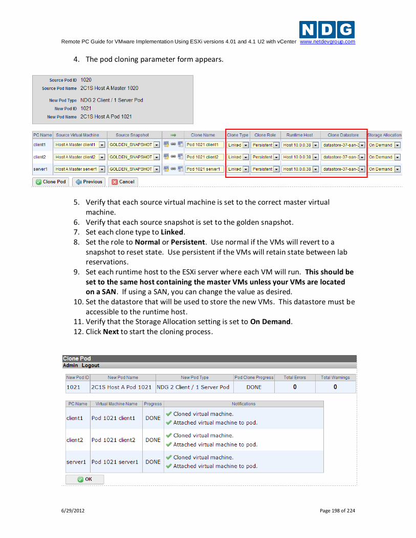
Remote PC Guide for VMware Implementation Using ESXi versions 4.01 and 4.1 U2 with vCenter www.netdevgroup.com
6/29/2012 Page 198 of 224
4. The pod cloning parameter form appears.
5. Verify that each source virtual machine is set to the correct master virtual machine.
6. Verify that each source snapshot is set to the golden snapshot. 7. Set each clone type to Linked. 8. Set the role to Normal or Persistent. Use normal if the VMs will revert to a
snapshot to reset state. Use persistent if the VMs will retain state between lab reservations.
9. Set each runtime host to the ESXi server where each VM will run. This should be set to the same host containing the master VMs unless your VMs are located on a SAN. If using a SAN, you can change the value as desired.
10. Set the datastore that will be used to store the new VMs. This datastore must be accessible to the runtime host.
11. Verify that the Storage Allocation setting is set to On Demand. 12. Click Next to start the cloning process.
Remote PC Guide for VMware Implementation Using ESXi versions 4.01 and 4.1 U2 with vCenter www.netdevgroup.com
6/29/2012 Page 199 of 224
9.4 Tasks to Perform After Pod Cloning
Here are some additional tasks that may be required after pod cloning.
If you want to restrict access to the new pod, use the Pod Assignment utility. This is often the case with persistent pods where you want to assign virtual machines to a student or team for a long period of time.
If the pod contains normal VMs that should revert to snapshot, take a snapshot of each new VM using the vSphere client. Make sure each remote PC is set to revert to this snapshot.
If the virtual pod does not support automatic networking, be sure to bind each VM to the proper port group using the vSphere client. If your VMs will revert to a snapshot, be sure your snapshot is taken after this binding is made.
When you are finished with all tasks, do not forget to bring the pod online, otherwise it
will not appear in the scheduler.
9.5 Saving Time on Subsequent Pod Cloning
In our last example, we cloned the master pod (MP1) for the first time. We had to change several parameters on the pod cloning form to produce the cloned pod (CP1). You could produce a second and third pod (CP2 & CP3) by cloning MP1 repeatedly. However, you will have to make the same form changes again and again. A more efficient way to produce CP2 and CP3 is to clone pod CP1. When NETLAB+ sees that CP1 is based on linked clones, it will assume you want to create a similar pod using linked clones based on the same master VMs. The default values will be the same as those you set for CP1, eliminating the need for changes. In most cases, you can click the Clone Pod button without form changes and NETLAB+ will produce the correct result.
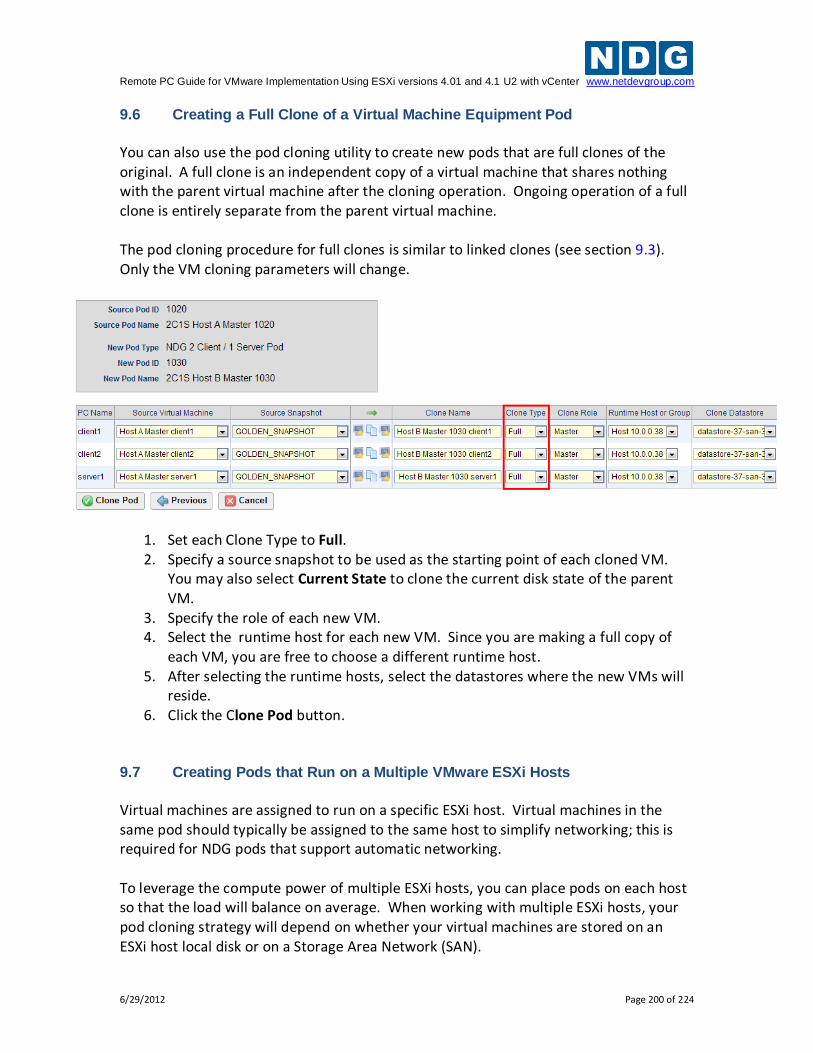
Remote PC Guide for VMware Implementation Using ESXi versions 4.01 and 4.1 U2 with vCenter www.netdevgroup.com
6/29/2012 Page 200 of 224
9.6 Creating a Full Clone of a Virtual Machine Equipment Pod
You can also use the pod cloning utility to create new pods that are full clones of the original. A full clone is an independent copy of a virtual machine that shares nothing with the parent virtual machine after the cloning operation. Ongoing operation of a full clone is entirely separate from the parent virtual machine. The pod cloning procedure for full clones is similar to linked clones (see section 9.3). Only the VM cloning parameters will change.
1. Set each Clone Type to Full. 2. Specify a source snapshot to be used as the starting point of each cloned VM.
You may also select Current State to clone the current disk state of the parent VM.
3. Specify the role of each new VM. 4. Select the runtime host for each new VM. Since you are making a full copy of
each VM, you are free to choose a different runtime host. 5. After selecting the runtime hosts, select the datastores where the new VMs will
reside. 6. Click the Clone Pod button.
9.7 Creating Pods that Run on a Multiple VMware ESXi Hosts
Virtual machines are assigned to run on a specific ESXi host. Virtual machines in the same pod should typically be assigned to the same host to simplify networking; this is required for NDG pods that support automatic networking. To leverage the compute power of multiple ESXi hosts, you can place pods on each host so that the load will balance on average. When working with multiple ESXi hosts, your pod cloning strategy will depend on whether your virtual machines are stored on an ESXi host local disk or on a Storage Area Network (SAN).
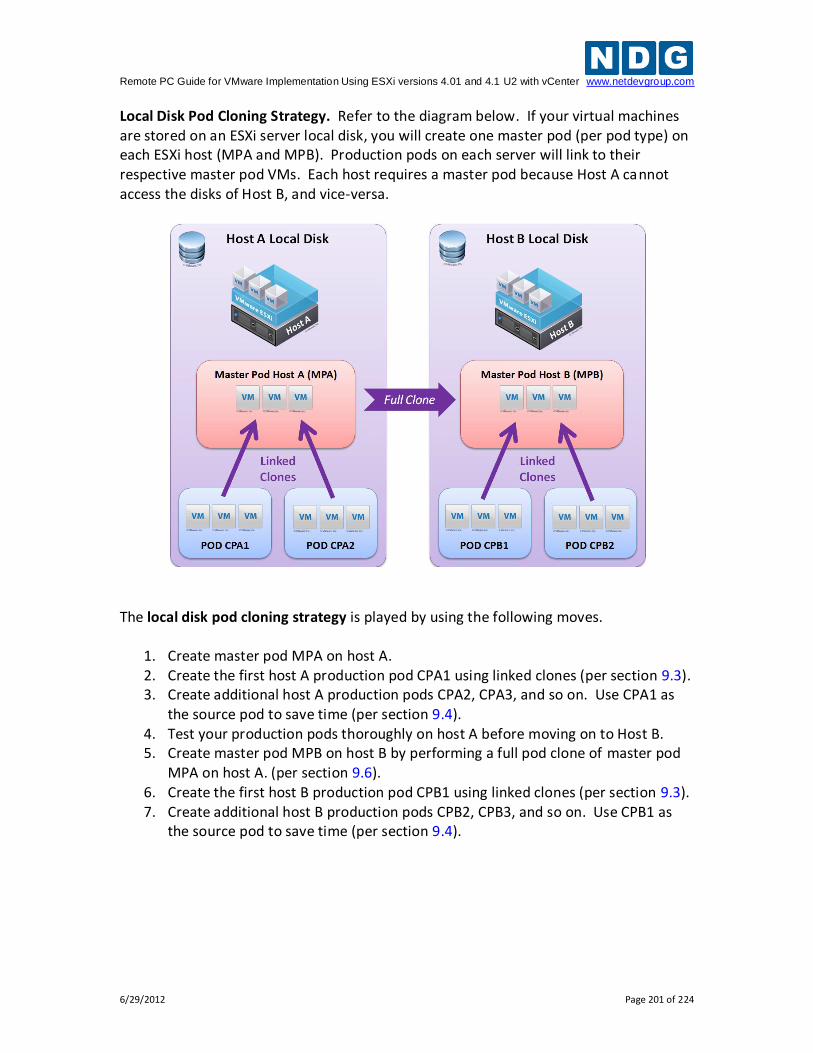
Remote PC Guide for VMware Implementation Using ESXi versions 4.01 and 4.1 U2 with vCenter www.netdevgroup.com
6/29/2012 Page 201 of 224
Local Disk Pod Cloning Strategy. Refer to the diagram below. If your virtual machines are stored on an ESXi server local disk, you will create one master pod (per pod type) on each ESXi host (MPA and MPB). Production pods on each server will link to their respective master pod VMs. Each host requires a master pod because Host A cannot access the disks of Host B, and vice-versa.
The local disk pod cloning strategy is played by using the following moves.
1. Create master pod MPA on host A. 2. Create the first host A production pod CPA1 using linked clones (per section 9.3). 3. Create additional host A production pods CPA2, CPA3, and so on. Use CPA1 as
the source pod to save time (per section 9.4). 4. Test your production pods thoroughly on host A before moving on to Host B. 5. Create master pod MPB on host B by performing a full pod clone of master pod
MPA on host A. (per section 9.6). 6. Create the first host B production pod CPB1 using linked clones (per section 9.3). 7. Create additional host B production pods CPB2, CPB3, and so on. Use CPB1 as
the source pod to save time (per section 9.4).
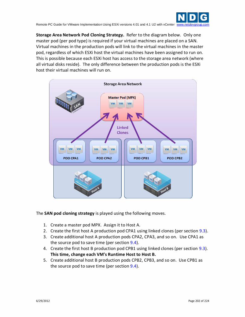
Remote PC Guide for VMware Implementation Using ESXi versions 4.01 and 4.1 U2 with vCenter www.netdevgroup.com
6/29/2012 Page 202 of 224
Storage Area Network Pod Cloning Strategy. Refer to the diagram below. Only one master pod (per pod type) is required if your virtual machines are placed on a SAN. Virtual machines in the production pods will link to the virtual machines in the master pod, regardless of which ESXi host the virtual machines have been assigned to run on. This is possible because each ESXi host has access to the storage area network (where all virtual disks reside). The only difference between the production pods is the ESXi host their virtual machines will run on.
The SAN pod cloning strategy is played using the following moves.
1. Create a master pod MPX. Assign it to Host A. 2. Create the first host A production pod CPA1 using linked clones (per section 9.3). 3. Create additional host A production pods CPA2, CPA3, and so on. Use CPA1 as
the source pod to save time (per section 9.4). 4. Create the first host B production pod CPB1 using linked clones (per section 9.3).
This time, change each VM's Runtime Host to Host B. 5. Create additional host B production pods CPB2, CPB3, and so on. Use CPB1 as
the source pod to save time (per section 9.4).
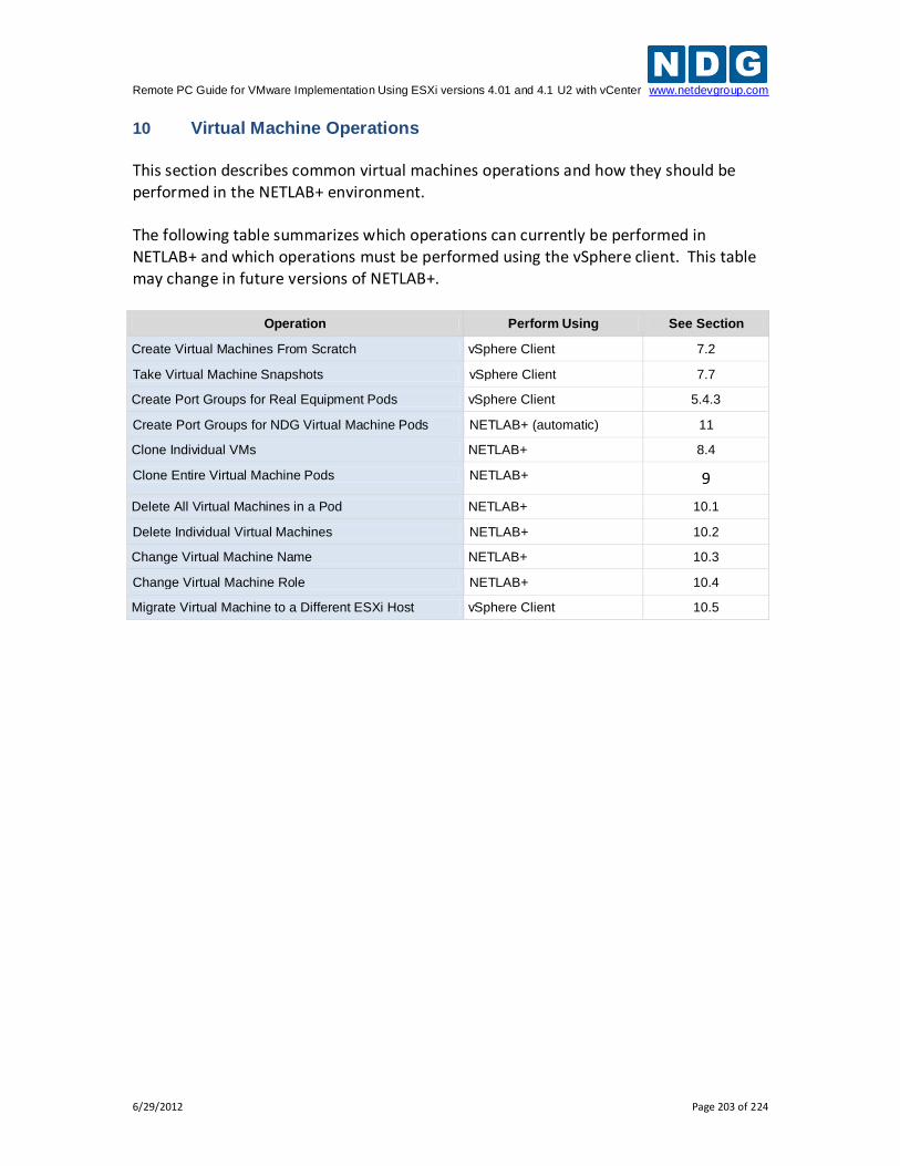
Remote PC Guide for VMware Implementation Using ESXi versions 4.01 and 4.1 U2 with vCenter www.netdevgroup.com
6/29/2012 Page 203 of 224
10 Virtual Machine Operations This section describes common virtual machines operations and how they should be performed in the NETLAB+ environment. The following table summarizes which operations can currently be performed in NETLAB+ and which operations must be performed using the vSphere client. This table may change in future versions of NETLAB+.
Operation Perform Using See Section
Create Virtual Machines From Scratch vSphere Client 7.2
Take Virtual Machine Snapshots vSphere Client 7.7
Create Port Groups for Real Equipment Pods vSphere Client 5.4.3
Create Port Groups for NDG Virtual Machine Pods NETLAB+ (automatic) 11
Clone Individual VMs NETLAB+ 8.4
Clone Entire Virtual Machine Pods NETLAB+ 9
Delete All Virtual Machines in a Pod NETLAB+ 10.1
Delete Individual Virtual Machines NETLAB+ 10.2
Change Virtual Machine Name NETLAB+ 10.3
Change Virtual Machine Role NETLAB+ 10.4
Migrate Virtual Machine to a Different ESXi Host vSphere Client 10.5
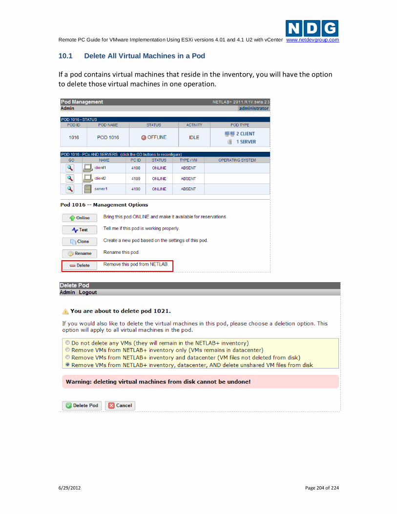
Remote PC Guide for VMware Implementation Using ESXi versions 4.01 and 4.1 U2 with vCenter www.netdevgroup.com
6/29/2012 Page 204 of 224
10.1 Delete All Virtual Machines in a Pod
If a pod contains virtual machines that reside in the inventory, you will have the option to delete those virtual machines in one operation.
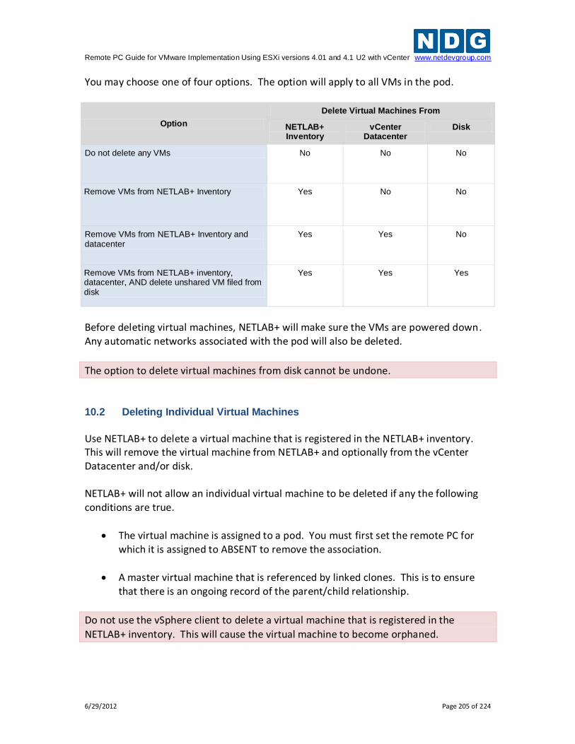
Remote PC Guide for VMware Implementation Using ESXi versions 4.01 and 4.1 U2 with vCenter www.netdevgroup.com
6/29/2012 Page 205 of 224
You may choose one of four options. The option will apply to all VMs in the pod.
Option
Delete Virtual Machines From
NETLAB+ Inventory
vCenter Datacenter
Disk
Do not delete any VMs No No No
Remove VMs from NETLAB+ Inventory Yes No No
Remove VMs from NETLAB+ Inventory and datacenter
Yes Yes No
Remove VMs from NETLAB+ inventory, datacenter, AND delete unshared VM filed from disk
Yes Yes Yes
Before deleting virtual machines, NETLAB+ will make sure the VMs are powered down. Any automatic networks associated with the pod will also be deleted.
The option to delete virtual machines from disk cannot be undone.
10.2 Deleting Individual Virtual Machines
Use NETLAB+ to delete a virtual machine that is registered in the NETLAB+ inventory. This will remove the virtual machine from NETLAB+ and optionally from the vCenter Datacenter and/or disk. NETLAB+ will not allow an individual virtual machine to be deleted if any the following conditions are true.
The virtual machine is assigned to a pod. You must first set the remote PC for which it is assigned to ABSENT to remove the association.
A master virtual machine that is referenced by linked clones. This is to ensure that there is an ongoing record of the parent/child relationship.
Do not use the vSphere client to delete a virtual machine that is registered in the
NETLAB+ inventory. This will cause the virtual machine to become orphaned.
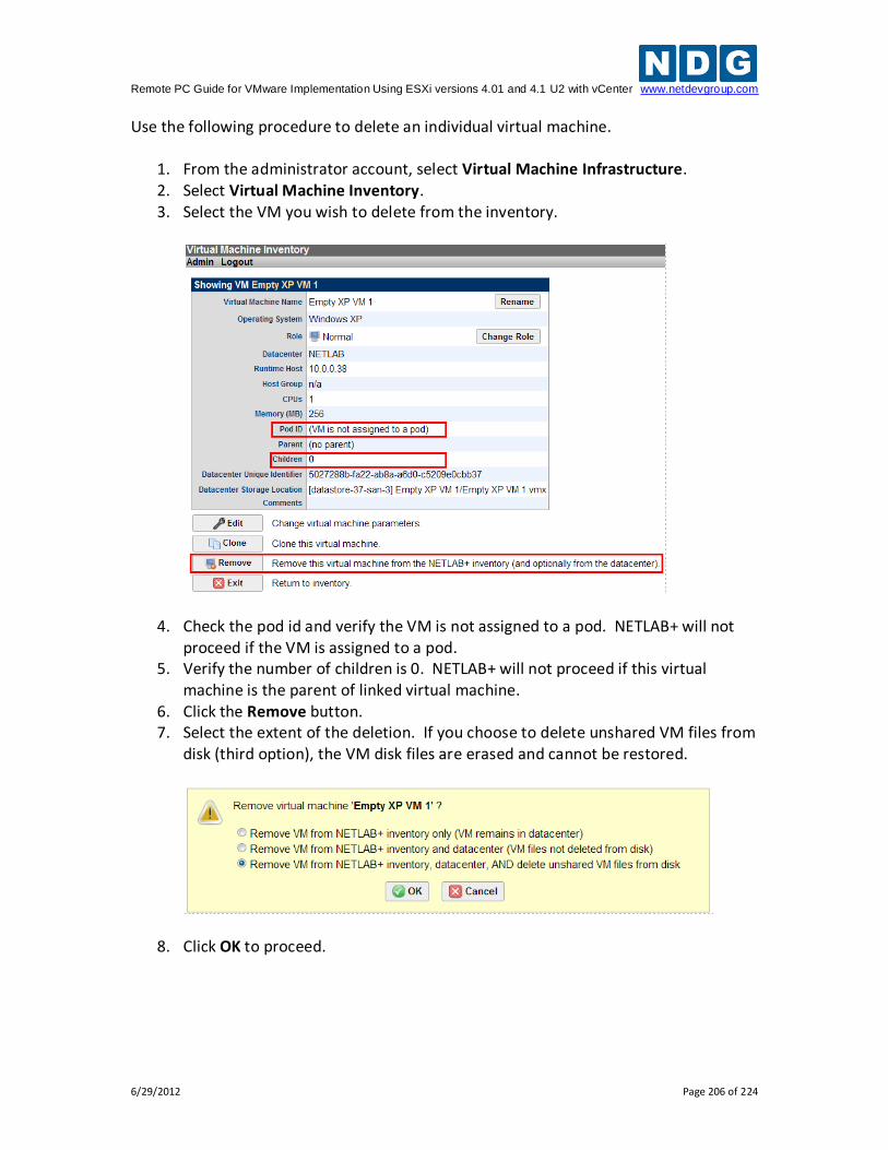
Remote PC Guide for VMware Implementation Using ESXi versions 4.01 and 4.1 U2 with vCenter www.netdevgroup.com
6/29/2012 Page 206 of 224
Use the following procedure to delete an individual virtual machine.
1. From the administrator account, select Virtual Machine Infrastructure. 2. Select Virtual Machine Inventory. 3. Select the VM you wish to delete from the inventory.
4. Check the pod id and verify the VM is not assigned to a pod. NETLAB+ will not proceed if the VM is assigned to a pod.
5. Verify the number of children is 0. NETLAB+ will not proceed if this virtual machine is the parent of linked virtual machine.
6. Click the Remove button. 7. Select the extent of the deletion. If you choose to delete unshared VM files from
disk (third option), the VM disk files are erased and cannot be restored.
8. Click OK to proceed.
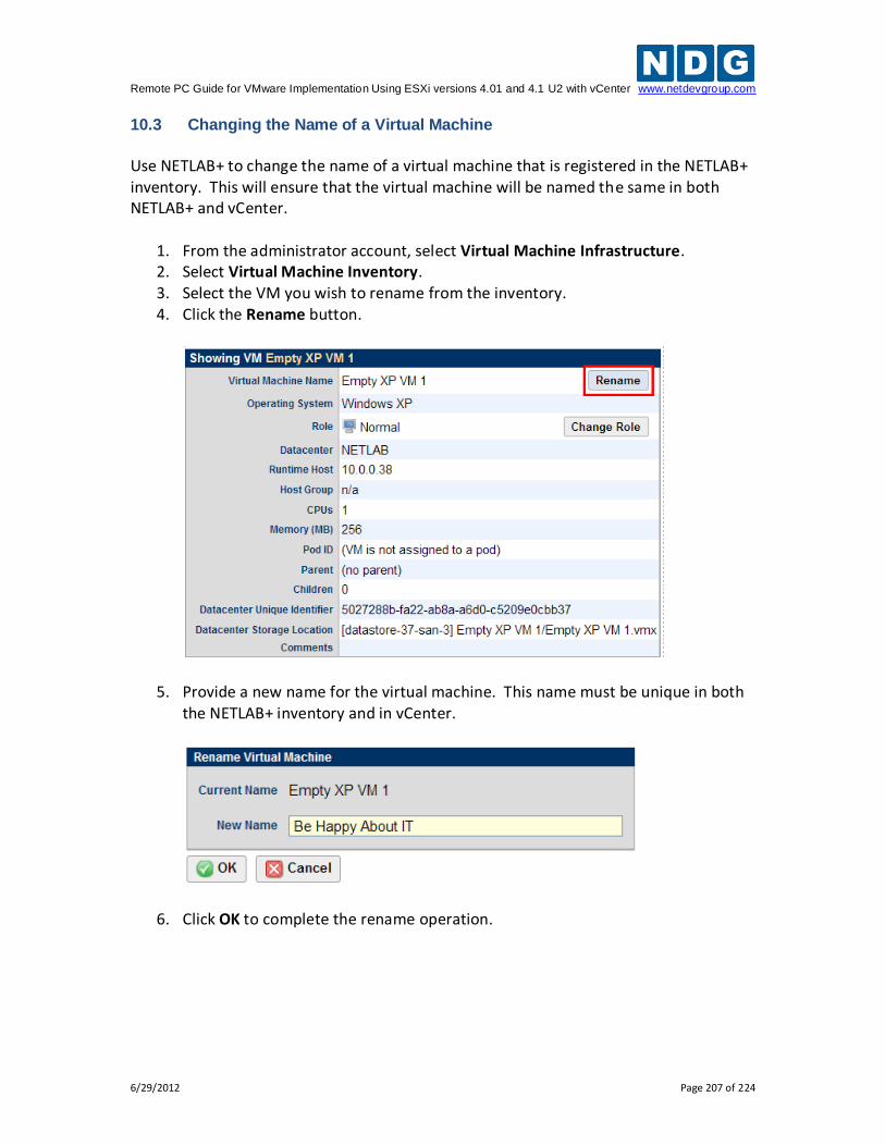
Remote PC Guide for VMware Implementation Using ESXi versions 4.01 and 4.1 U2 with vCenter www.netdevgroup.com
6/29/2012 Page 207 of 224
10.3 Changing the Name of a Virtual Machine
Use NETLAB+ to change the name of a virtual machine that is registered in the NETLAB+ inventory. This will ensure that the virtual machine will be named the same in both NETLAB+ and vCenter.
1. From the administrator account, select Virtual Machine Infrastructure. 2. Select Virtual Machine Inventory. 3. Select the VM you wish to rename from the inventory. 4. Click the Rename button.
5. Provide a new name for the virtual machine. This name must be unique in both the NETLAB+ inventory and in vCenter.
6. Click OK to complete the rename operation.
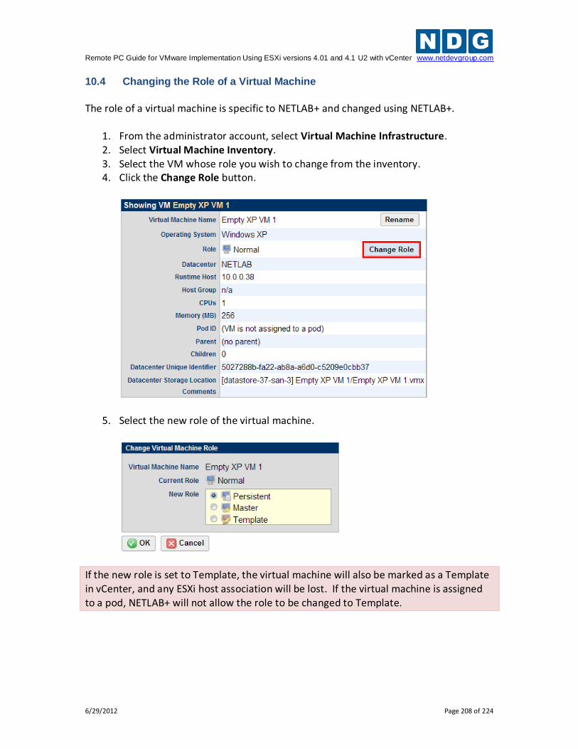
Remote PC Guide for VMware Implementation Using ESXi versions 4.01 and 4.1 U2 with vCenter www.netdevgroup.com
6/29/2012 Page 208 of 224
10.4 Changing the Role of a Virtual Machine
The role of a virtual machine is specific to NETLAB+ and changed using NETLAB+.
1. From the administrator account, select Virtual Machine Infrastructure. 2. Select Virtual Machine Inventory. 3. Select the VM whose role you wish to change from the inventory. 4. Click the Change Role button.
5. Select the new role of the virtual machine.
If the new role is set to Template, the virtual machine will also be marked as a Template in vCenter, and any ESXi host association will be lost. If the virtual machine is assigned to a pod, NETLAB+ will not allow the role to be changed to Template.
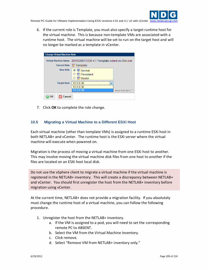
Remote PC Guide for VMware Implementation Using ESXi versions 4.01 and 4.1 U2 with vCenter www.netdevgroup.com
6/29/2012 Page 209 of 224
6. If the current role is Template, you must also specify a target runtime host for the virtual machine. This is because non-template VMs are associated with a runtime host. The virtual machine will be set to run on the target host and will no longer be marked as a template in vCenter.
7. Click OK to complete the role change. 10.5 Migrating a Virtual Machine to a Different ESXi Host
Each virtual machine (other than template VMs) is assigned to a runtime ESXi host in both NETLAB+ and vCenter. The runtime host is the ESXi server where the virtual machine will execute when powered on. Migration is the process of moving a virtual machine from one ESXi host to another. This may involve moving the virtual machine disk files from one host to another if the files are located on an ESXi host local disk.
Do not use the vSphere client to migrate a virtual machine if the virtual machine is registered in the NETLAB+ inventory. This will create a discrepancy between NETLAB+ and vCenter. You should first unregister the host from the NETLAB+ inventory before migration using vCenter.
At the current time, NETLAB+ does not provide a migration facility. If you absolutely must change the runtime host of a virtual machine, you can follow the following procedure.
1. Unregister the host from the NETLAB+ inventory. a. If the VM is assigned to a pod, you will need to set the corresponding
remote PC to ABSENT. b. Select the VM from the Virtual Machine Inventory. c. Click remove. d. Select "Remove VM from NETLAB+ inventory only."
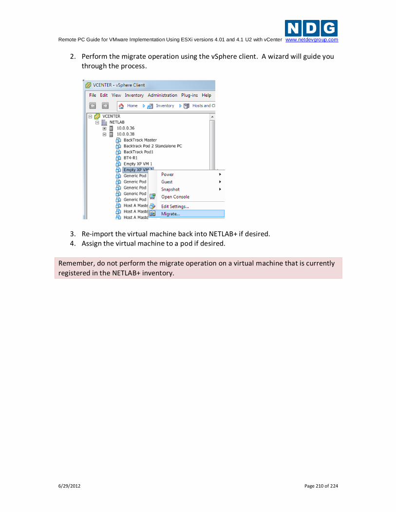
Remote PC Guide for VMware Implementation Using ESXi versions 4.01 and 4.1 U2 with vCenter www.netdevgroup.com
6/29/2012 Page 210 of 224
2. Perform the migrate operation using the vSphere client. A wizard will guide you through the process.
3. Re-import the virtual machine back into NETLAB+ if desired. 4. Assign the virtual machine to a pod if desired.
Remember, do not perform the migrate operation on a virtual machine that is currently
registered in the NETLAB+ inventory.
Remote PC Guide for VMware Implementation Using ESXi versions 4.01 and 4.1 U2 with vCenter www.netdevgroup.com
6/29/2012 Page 211 of 224
11 Using NDG Automated Pods
NDG provides many standard topologies that support special automation for virtual machines. Pods using these topologies are created using the techniques described earlier in this guide.
The automation described in this section requires VMware vCenter and the NETLAB+ Virtual Machine Inventory features as described in this guide.
11.1 NDG Virtual Machine Topologies
NDG standard topologies that contain only virtual machines can be replicated and deployed very quickly using a combination of pod cloning, automatic networking and automatic remote display setup features. The list of NDG automated virtual machine topologies includes:
25 automated client/server pods for General IT usage. For details see http://www.netdevgroup.com/content/generalit
An automated topology for CNSS 4011 cyber security. For details see http://www.netdevgroup.com/content/cybersecurity/topologies
An automated topology for the VMware IT Academy Install, Configure, Manage course. This pod is available to member organizations of the VMware IT Academy. For details see: http://www.netdevgroup.com/content/vmita and the pod specific guide in the NDG Lab Resource Center for VMware IT Academy.
Once production pods are created using the pod cloning utility, they are ready to go. When an automated pod is scheduled and lab reservation begins, the following automation takes place:
NETLAB+ will automatically create virtual switches and port groups required for the pod.
NETLAB+ will bind the virtual network adapters of each VM to the correct port group.
NETLAB+ will configure remote display parameters automatically. When the lab reservation is over, NETLAB+ will tear down the virtual switches and port groups created for the pod to free resources on the host.
Remote PC Guide for VMware Implementation Using ESXi versions 4.01 and 4.1 U2 with vCenter www.netdevgroup.com
6/29/2012 Page 212 of 224
11.2 NDG Real Equipment Topologies
As of NETLAB+ version 2011.R2, automatic networking and automatic remote display setup is supported on the following topologies:
Multi-purpose Academy Pod (MAP)
Cuatro Router Pod (CRP)
Cuatro Switch Pod (CSP)
LAN Switching Pod (LSP)
Network Security Pod (NSP)
Basic Router Pod Version 2 (BRPv2)
Basic Switch Pod Version 2 (BSPv2) When a pod is scheduled and lab reservation begins, the following automation takes place:
NETLAB+ will automatically calculate the control switch VLANs that are required for the pod.
NETLAB+ will automatically create VLAN based port groups on the virtual machine host's inside virtual switch.
NETLAB+ will bind the virtual network adapters of each VM to the correct port group.
NETLAB+ will configure remote display parameters automatically. When the lab reservation is over, NETLAB+ will tear down the port groups created for the pod to free resources on the host.
For automatic networking on real equipment pods, you must setup the inside virtual switch on each ESXi host (section 5.4). You must also provide the name of the virtual switch in the NETLAB+ virtual machine host setup (section 5.6). Automatic networking
will not occur if these tasks are not performed.
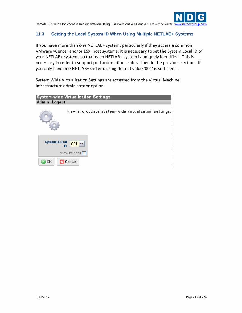
Remote PC Guide for VMware Implementation Using ESXi versions 4.01 and 4.1 U2 with vCenter www.netdevgroup.com
6/29/2012 Page 213 of 224
11.3 Setting the Local System ID When Using Multiple NETLAB+ Systems
If you have more than one NETLAB+ system, particularly if they access a common VMware vCenter and/or ESXi host systems, it is necessary to set the System Local ID of your NETLAB+ systems so that each NETLAB+ system is uniquely identified. This is necessary in order to support pod automation as described in the previous section. If you only have one NETLAB+ system, using default value '001' is sufficient. System Wide Virtualization Settings are accessed from the Virtual Machine Infrastructure administrator option.
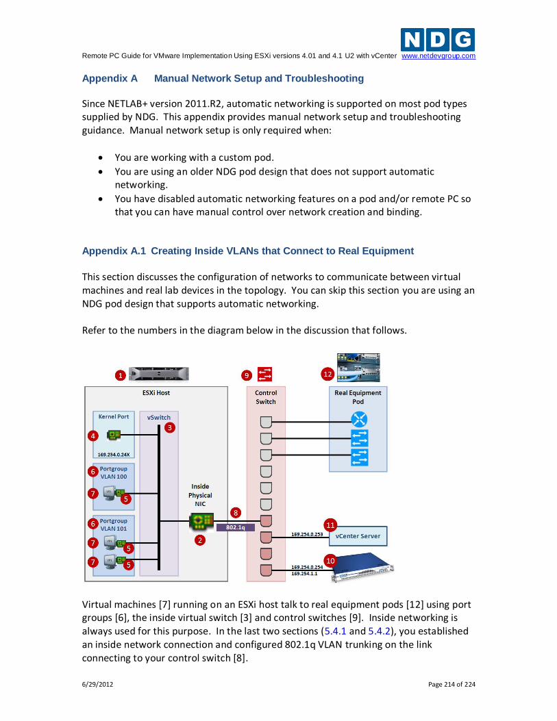
Remote PC Guide for VMware Implementation Using ESXi versions 4.01 and 4.1 U2 with vCenter www.netdevgroup.com
6/29/2012 Page 214 of 224
Appendix A Manual Network Setup and Troubleshooting
Since NETLAB+ version 2011.R2, automatic networking is supported on most pod types supplied by NDG. This appendix provides manual network setup and troubleshooting guidance. Manual network setup is only required when:
You are working with a custom pod.
You are using an older NDG pod design that does not support automatic networking.
You have disabled automatic networking features on a pod and/or remote PC so that you can have manual control over network creation and binding.
Appendix A.1 Creating Inside VLANs that Connect to Real Equipment
This section discusses the configuration of networks to communicate between virtual machines and real lab devices in the topology. You can skip this section you are using an NDG pod design that supports automatic networking. Refer to the numbers in the diagram below in the discussion that follows.
Virtual machines [7] running on an ESXi host talk to real equipment pods [12] using port groups [6], the inside virtual switch [3] and control switches [9]. Inside networking is always used for this purpose. In the last two sections (5.4.1 and 5.4.2), you established an inside network connection and configured 802.1q VLAN trunking on the link connecting to your control switch [8].
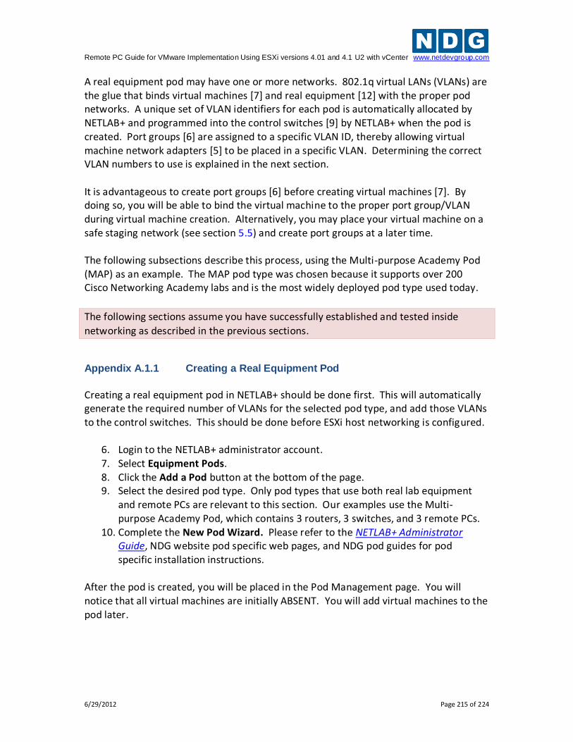
Remote PC Guide for VMware Implementation Using ESXi versions 4.01 and 4.1 U2 with vCenter www.netdevgroup.com
6/29/2012 Page 215 of 224
A real equipment pod may have one or more networks. 802.1q virtual LANs (VLANs) are the glue that binds virtual machines [7] and real equipment [12] with the proper pod networks. A unique set of VLAN identifiers for each pod is automatically allocated by NETLAB+ and programmed into the control switches [9] by NETLAB+ when the pod is created. Port groups [6] are assigned to a specific VLAN ID, thereby allowing virtual machine network adapters [5] to be placed in a specific VLAN. Determining the correct VLAN numbers to use is explained in the next section. It is advantageous to create port groups [6] before creating virtual machines [7]. By doing so, you will be able to bind the virtual machine to the proper port group/VLAN during virtual machine creation. Alternatively, you may place your virtual machine on a safe staging network (see section 5.5) and create port groups at a later time. The following subsections describe this process, using the Multi-purpose Academy Pod (MAP) as an example. The MAP pod type was chosen because it supports over 200 Cisco Networking Academy labs and is the most widely deployed pod type used today.
The following sections assume you have successfully established and tested inside
networking as described in the previous sections. Appendix A.1.1 Creating a Real Equipment Pod
Creating a real equipment pod in NETLAB+ should be done first. This will automatically generate the required number of VLANs for the selected pod type, and add those VLANs to the control switches. This should be done before ESXi host networking is configured.
6. Login to the NETLAB+ administrator account. 7. Select Equipment Pods. 8. Click the Add a Pod button at the bottom of the page. 9. Select the desired pod type. Only pod types that use both real lab equipment
and remote PCs are relevant to this section. Our examples use the Multi-purpose Academy Pod, which contains 3 routers, 3 switches, and 3 remote PCs.
10. Complete the New Pod Wizard. Please refer to the NETLAB+ Administrator Guide, NDG website pod specific web pages, and NDG pod guides for pod specific installation instructions.
After the pod is created, you will be placed in the Pod Management page. You will notice that all virtual machines are initially ABSENT. You will add virtual machines to the pod later.
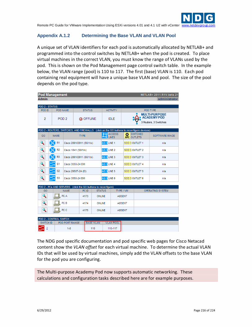
Remote PC Guide for VMware Implementation Using ESXi versions 4.01 and 4.1 U2 with vCenter www.netdevgroup.com
6/29/2012 Page 216 of 224
Appendix A.1.2 Determining the Base VLAN and VLAN Pool
A unique set of VLAN identifiers for each pod is automatically allocated by NETLAB+ and programmed into the control switches by NETLAB+ when the pod is created. To place virtual machines in the correct VLAN, you must know the range of VLANs used by the pod. This is shown on the Pod Management page control switch table. In the example below, the VLAN range (pool) is 110 to 117. The first (base) VLAN is 110. Each pod containing real equipment will have a unique base VLAN and pool. The size of the pool depends on the pod type.
The NDG pod specific documentation and pod specific web pages for Cisco Netacad content show the VLAN offset for each virtual machine. To determine the actual VLAN IDs that will be used by virtual machines, simply add the VLAN offsets to the base VLAN for the pod you are configuring.
The Multi-purpose Academy Pod now supports automatic networking. These
calculations and configuration tasks described here are for example purposes.
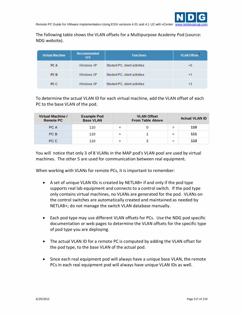
Remote PC Guide for VMware Implementation Using ESXi versions 4.01 and 4.1 U2 with vCenter www.netdevgroup.com
6/29/2012 Page 217 of 224
The following table shows the VLAN offsets for a Multipurpose Academy Pod (source: NDG website).
To determine the actual VLAN ID for each virtual machine, add the VLAN offset of each PC to the base VLAN of the pod.
Virtual Machine / Remote PC
Example Pod Base VLAN
VLAN Offset
From Table Above Actual VLAN ID
PC A 110 + 0 = 110
PC B 110 + 1 = 111
PC C 110 + 3 = 113
You will notice that only 3 of 8 VLANs in the MAP pod's VLAN pool are used by virtual machines. The other 5 are used for communication between real equipment. When working with VLANs for remote PCs, it is important to remember:
A set of unique VLAN IDs is created by NETLAB+ if and only if the pod type supports real lab equipment and connects to a control switch. If the pod type only contains virtual machines, no VLANs are generated for the pod. VLANs on the control switches are automatically created and maintained as needed by NETLAB+; do not manage the switch VLAN database manually.
Each pod type may use different VLAN offsets for PCs. Use the NDG pod specific documentation or web pages to determine the VLAN offsets for the specific type of pod type you are deploying.
The actual VLAN ID for a remote PC is computed by adding the VLAN offset for the pod type, to the base VLAN of the actual pod.
Since each real equipment pod will always have a unique base VLAN, the remote PCs in each real equipment pod will always have unique VLAN IDs as well.
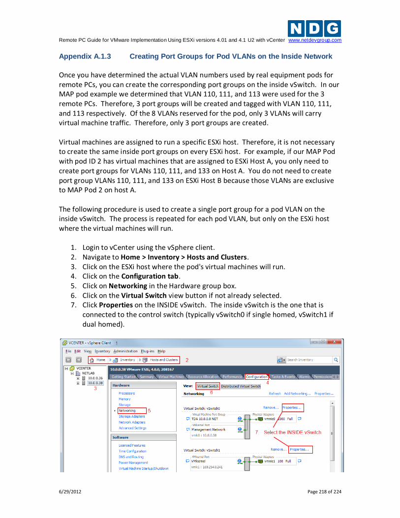
Remote PC Guide for VMware Implementation Using ESXi versions 4.01 and 4.1 U2 with vCenter www.netdevgroup.com
6/29/2012 Page 218 of 224
Appendix A.1.3 Creating Port Groups for Pod VLANs on the Inside Network
Once you have determined the actual VLAN numbers used by real equipment pods for remote PCs, you can create the corresponding port groups on the inside vSwitch. In our MAP pod example we determined that VLAN 110, 111, and 113 were used for the 3 remote PCs. Therefore, 3 port groups will be created and tagged with VLAN 110, 111, and 113 respectively. Of the 8 VLANs reserved for the pod, only 3 VLANs will carry virtual machine traffic. Therefore, only 3 port groups are created. Virtual machines are assigned to run a specific ESXi host. Therefore, it is not necessary to create the same inside port groups on every ESXi host. For example, if our MAP Pod with pod ID 2 has virtual machines that are assigned to ESXi Host A, you only need to create port groups for VLANs 110, 111, and 133 on Host A. You do not need to create port group VLANs 110, 111, and 133 on ESXi Host B because those VLANs are exclusive to MAP Pod 2 on host A. The following procedure is used to create a single port group for a pod VLAN on the inside vSwitch. The process is repeated for each pod VLAN, but only on the ESXi host where the virtual machines will run.
1. Login to vCenter using the vSphere client. 2. Navigate to Home > Inventory > Hosts and Clusters. 3. Click on the ESXi host where the pod's virtual machines will run. 4. Click on the Configuration tab. 5. Click on Networking in the Hardware group box. 6. Click on the Virtual Switch view button if not already selected. 7. Click Properties on the INSIDE vSwitch. The inside vSwitch is the one that is
connected to the control switch (typically vSwitch0 if single homed, vSwitch1 if dual homed).
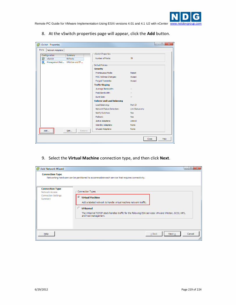
Remote PC Guide for VMware Implementation Using ESXi versions 4.01 and 4.1 U2 with vCenter www.netdevgroup.com
6/29/2012 Page 219 of 224
8. At the vSwitch properties page will appear, click the Add button.
9. Select the Virtual Machine connection type, and then click Next.
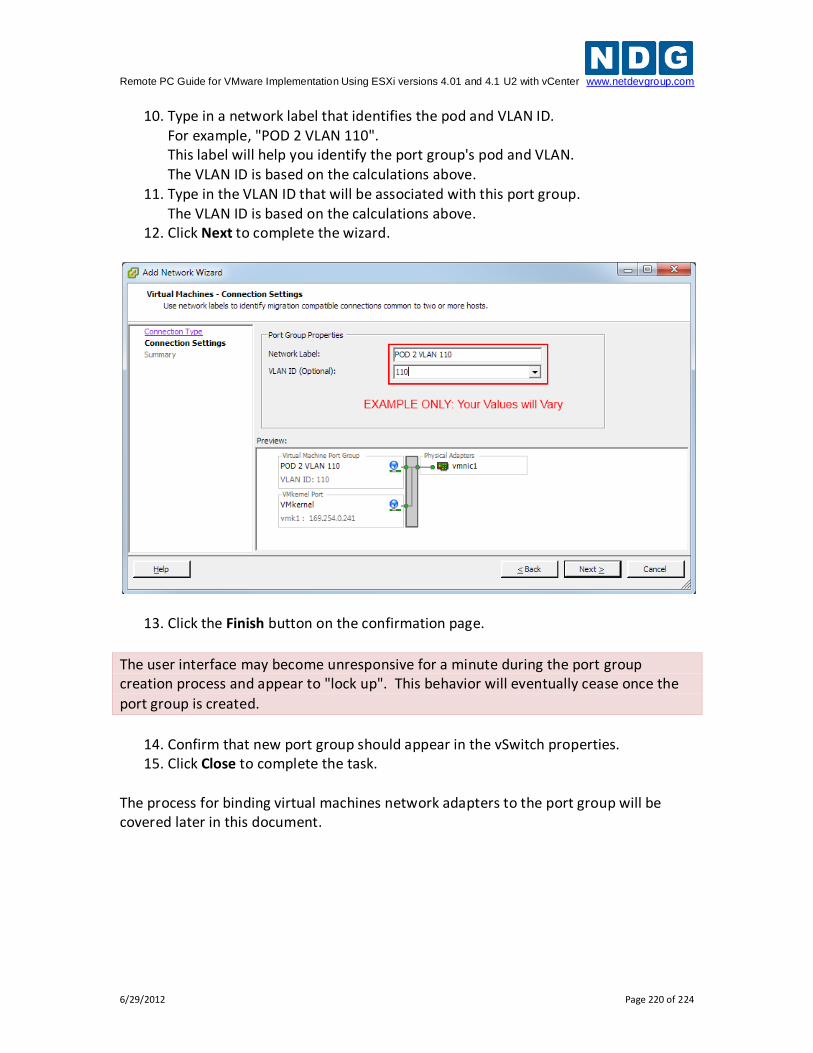
Remote PC Guide for VMware Implementation Using ESXi versions 4.01 and 4.1 U2 with vCenter www.netdevgroup.com
6/29/2012 Page 220 of 224
10. Type in a network label that identifies the pod and VLAN ID. For example, "POD 2 VLAN 110". This label will help you identify the port group's pod and VLAN. The VLAN ID is based on the calculations above.
11. Type in the VLAN ID that will be associated with this port group. The VLAN ID is based on the calculations above.
12. Click Next to complete the wizard.
13. Click the Finish button on the confirmation page.
The user interface may become unresponsive for a minute during the port group creation process and appear to "lock up". This behavior will eventually cease once the
port group is created.
14. Confirm that new port group should appear in the vSwitch properties. 15. Click Close to complete the task.
The process for binding virtual machines network adapters to the port group will be covered later in this document.
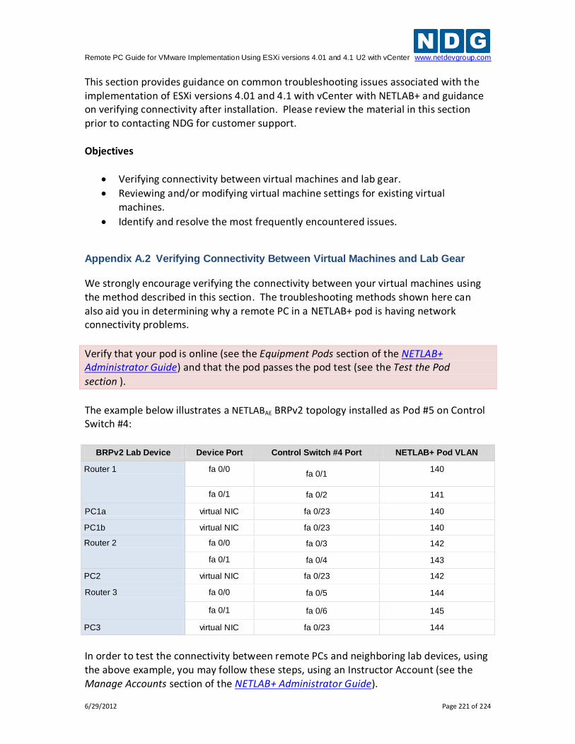
Remote PC Guide for VMware Implementation Using ESXi versions 4.01 and 4.1 U2 with vCenter www.netdevgroup.com
6/29/2012 Page 221 of 224
This section provides guidance on common troubleshooting issues associated with the implementation of ESXi versions 4.01 and 4.1 with vCenter with NETLAB+ and guidance on verifying connectivity after installation. Please review the material in this section prior to contacting NDG for customer support. Objectives
Verifying connectivity between virtual machines and lab gear.
Reviewing and/or modifying virtual machine settings for existing virtual machines.
Identify and resolve the most frequently encountered issues.
Appendix A.2 Verifying Connectivity Between Virtual Machines and Lab Gear
We strongly encourage verifying the connectivity between your virtual machines using the method described in this section. The troubleshooting methods shown here can also aid you in determining why a remote PC in a NETLAB+ pod is having network connectivity problems.
Verify that your pod is online (see the Equipment Pods section of the NETLAB+ Administrator Guide) and that the pod passes the pod test (see the Test the Pod
section ).
The example below illustrates a NETLABAE BRPv2 topology installed as Pod #5 on Control Switch #4:
BRPv2 Lab Device Device Port Control Switch #4 Port NETLAB+ Pod VLAN
Router 1 fa 0/0 fa 0/1
140
fa 0/1 fa 0/2 141
PC1a virtual NIC fa 0/23 140
PC1b virtual NIC fa 0/23 140
Router 2 fa 0/0 fa 0/3 142
fa 0/1 fa 0/4 143
PC2 virtual NIC fa 0/23 142
Router 3 fa 0/0 fa 0/5 144
fa 0/1 fa 0/6 145
PC3 virtual NIC fa 0/23 144
In order to test the connectivity between remote PCs and neighboring lab devices, using the above example, you may follow these steps, using an Instructor Account (see the Manage Accounts section of the NETLAB+ Administrator Guide).
Remote PC Guide for VMware Implementation Using ESXi versions 4.01 and 4.1 U2 with vCenter www.netdevgroup.com
6/29/2012 Page 222 of 224
1. Make a lab reservation. 2. Configure IP addresses on the remote PCs and neighboring lab devices you will
be testing. 3. In the example above, PC1a and PC1b should share the same VLAN adapter, so
they should be able to ping each other. If they cannot ping each other, then you should review the following:
What VLAN adapter are PC1a and PC1b using? (refer to section 5.4.3. Is there a firewall installed or enabled on the virtual machine?
4. To verify the connectivity between remote PCs and neighboring lab devices, you
should test the following:
Ping from PC1a to R1 and vice versa.
Ping from PC1b to R1 and vice versa.
Ping from PC2 to R2 and vice versa.
Ping from PC3 to R3 and vice versa.
5. If you can ping from a remote PC to a neighboring lab device, but cannot ping from the lab device to the remote PC, then you may want to determine if there is a firewall installed or enabled on the virtual machine.
6. If any of the tests from step 4 completely fail (you cannot ping from remote PC to neighboring lab device and vice versa), then you will need to analyze the network traffic on the control switch. Using the above example, perform the following steps:
Connect a PC or terminal to the console port of the control switch.
Type “show vlan” or “show vlan brief” to view the VLAN status on the control switch.
The control switch console password is router. The enable secret password is cisco. These passwords are used by NETLAB+ automation and technical support - please do
not change them.
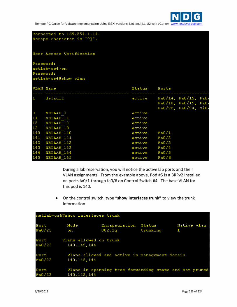
Remote PC Guide for VMware Implementation Using ESXi versions 4.01 and 4.1 U2 with vCenter www.netdevgroup.com
6/29/2012 Page 223 of 224
During a lab reservation, you will notice the active lab ports and their VLAN assignments. From the example above, Pod #5 is a BRPv2 installed on ports fa0/1 through fa0/6 on Control Switch #4. The base VLAN for this pod is 140.
On the control switch, type “show interfaces trunk” to view the trunk information.
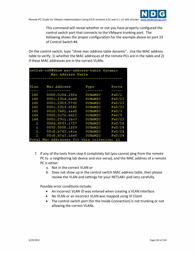
Remote PC Guide for VMware Implementation Using ESXi versions 4.01 and 4.1 U2 with vCenter www.netdevgroup.com
6/29/2012 Page 224 of 224
This command will reveal whether or not you have properly configured the control switch port that connects to the VMware trunking port. The following shows the proper configuration for the example above on port 23 of Control Switch #4.
On the control switch, type “show mac-address-table dynamic”. Use the MAC address table to verify: 1) whether the MAC addresses of the remote PCs are in the table and 2) if these MAC addresses are in the correct VLANs.
7. If any of the tests from step 4 completely fail (you cannot ping from the remote PC to a neighboring lab device and vice versa), and the MAC address of a remote PC is either:
a. Not in the correct VLAN or b. Does not show up in the control switch MAC address table, then please
review the VLAN and settings for your NETLAB+ pod very carefully.
Possible error conditions include:
An incorrect VLAN ID was entered when creating a VLAN interface.
No VLAN or an incorrect VLAN was mapped using VI Client
The control switch port (for the Inside Connection) is not trunking or not allowing the correct VLANs.