Embed Size (px)
Citation preview
Remote Sensing Basics | June 14-20, 2009
SLC-Off Gap FilledProduct Generation
Richard IrishSSAI, NASA’s Goddard Space Flight Center
Pat ScaramuzzaSAIC, Center for Earth Observations and Science (EROS)
Remote Sensing Basics | June 14-20, 2009
Scan Line Corrector Failure
On May 31, 2003, Landsat 7 experienced an anomaly causing the Scan Line Corrector (SLC) to stop functioning normally.
The telescope focuses energy onto a pair of motion compensation mirrors (i.e. SLC) where it is redirected to the focal planes and accounts for the compound effect of along-track orbital motion and cross-track scanning which leads to significant overlap and underlap in ground coverage between successive scans.
While missing data is lost, it was possible to modify existing algorithms to produce imagery containing roughly 80% of the expected scene.
The processed post-anomaly data continues to maintain its expected radiometric and geometric fidelity.
Remote Sensing Basics | June 14-20, 2009
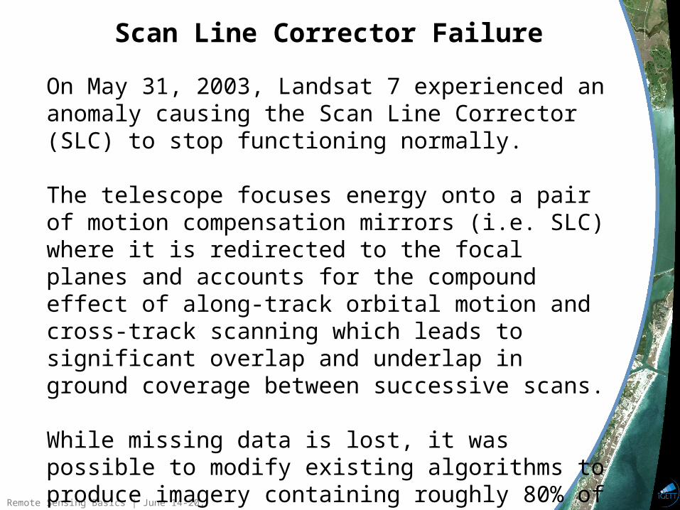
Scan Line Corrector
Remote Sensing Basics | June 14-20, 2009
SLC-off Archive Potential
Landsat 5 has outlived its design life by an astounding 22 years yet its demise will likely precede that of Landsat 7.
Over 660,000 SLC-off scenes have been acquired, archived, and are available for free. Many uniquely represent the only recent Landsat observations over foreign soil.
The goal of the algorithm presented here is to tap the value represented by the SLC-off archive by filling missing pixels with radiometry that has scientific purpose.
With a LDCM (Landsat - 8) scheduled for a late 2012 launch, there maybe no choice.
Remote Sensing Basics | June 14-20, 2009
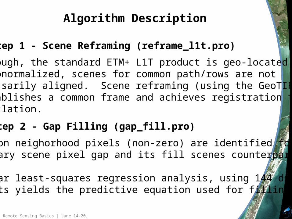
Algorithm Description
Step 1 - Scene Reframing (reframe_l1t.pro)
Step 2 - Gap Filling (gap_fill.pro)
Although, the standard ETM+ L1T product is geo-located and Orthonormalized, scenes for common path/rows are notnecessarily aligned. Scene reframing (using the GeoTIFF header) establishes a common frame and achieves registration through translation.
Common neighorhood pixels (non-zero) are identified for each primary scene pixel gap and its fill scenes counterparts.
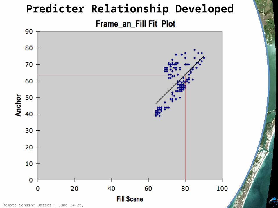
Linear least-squares regression analysis, using 144 data points yields the predictive equation used for filling.
Remote Sensing Basics | June 14-20, 2009
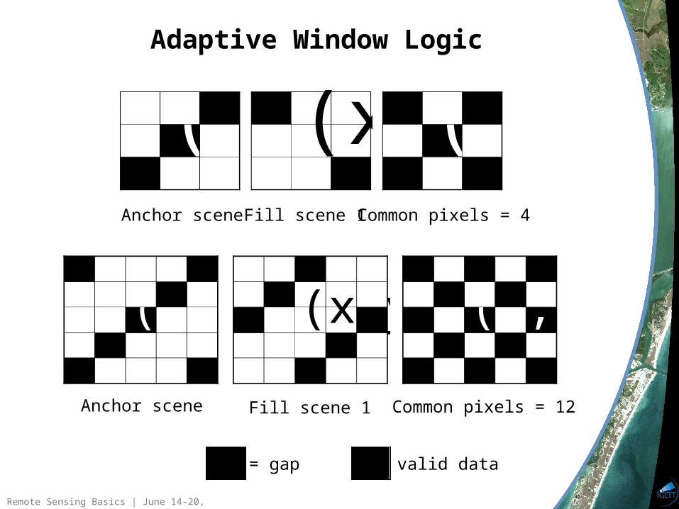
Adaptive Window Logic
(x,y)(x,y)(x,y)
(x,y) (x,y) (x,y)
Anchor scene Fill scene 1 Common pixels = 4
Anchor scene Fill scene 1 Common pixels = 12
= gap = valid data
Remote Sensing Basics | June 14-20, 2009
Predicter Relationship Developed
Remote Sensing Basics | June 14-20, 2009
Frame_and_fill The primary goal of this endeavor was to create freeware so anyone with a desire could take greater advantage of the ETM+ SLC-off archive.
Unfotunately, reframe_l1t.pro and gap_fill.pro require an IDL license to run.
Fortunately, ITT provides a Virtual Machine a mechanism for creating standalone applications called runtime distrubutions. The only penaltyis an ITT splash screen at program launch.
Creating a runtime distribution required learning the IDL GUI language,a treat, and creating a solitary application called frame_and_fill.
Currently versions exist for Windows - 32 and Mac PPC. Plans are to make additional versions for Mac Int (32, 64 bit), Windows-64, Linux and Solaris (32 and 64 bit).http://landsathandbook.gsfc.nasa.gov/handbook/software/gap_filling_software.html
Remote Sensing Basics | June 14-20, 2009
Frame_and_fill Data Staging Rules
The primary scene to be filled is termed the anchor scene. It MUST reside in a folder named anchor for the software to work.
The filler scenes reside in separate folders at the same directory level as the anchor folder.
They are so named fill_scene_1, fill_scene_2... to reflect their processing priority.
These folder naming conventions must be followed for the software to work.
Remote Sensing Basics | June 14-20, 2009
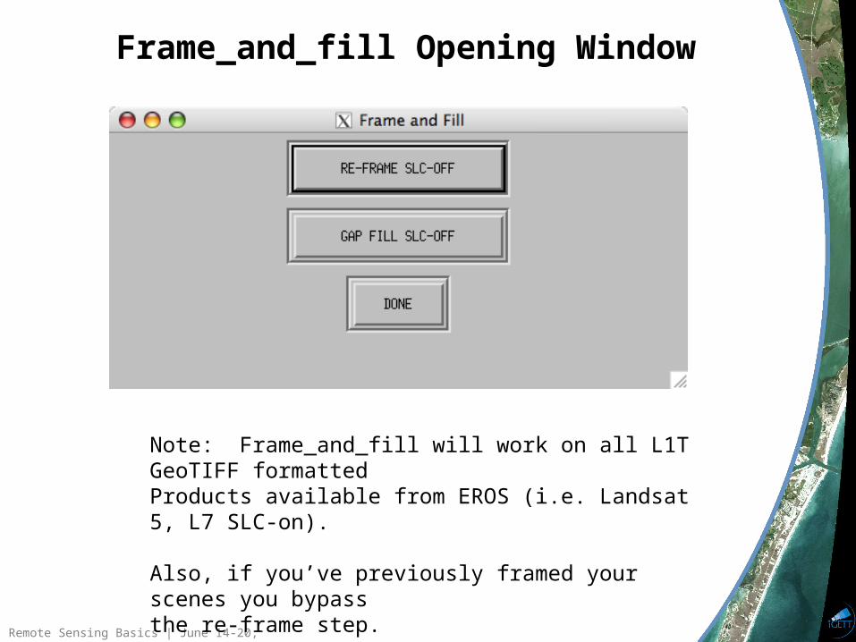
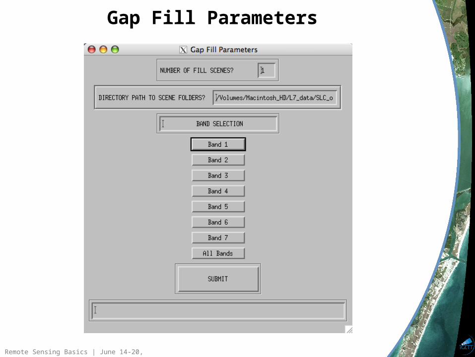
Frame_and_fill Opening Window
Note: Frame_and_fill will work on all L1T GeoTIFF formattedProducts available from EROS (i.e. Landsat 5, L7 SLC-on).
Also, if you’ve previously framed your scenes you bypassthe re-frame step.
Remote Sensing Basics | June 14-20, 2009
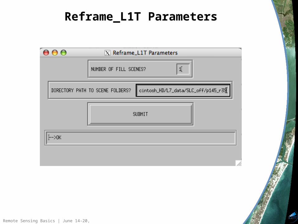
Reframe_L1T Parameters
Remote Sensing Basics | June 14-20, 2009
Gap Fill Parameters
Remote Sensing Basics | June 14-20, 2009
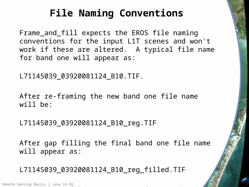
Frame_and_fill expects the EROS file naming conventions for the input L1T scenes and won't work if these are altered. A typical file name for band one will appear as: L71145039_03920081124_B10.TIF.
After re-framing the new band one file name will be: L71145039_03920081124_B10_reg.TIF
After gap filling the final band one file name will appear as: L71145039_03920081124_B10_reg_filled.TIF
Output band files are GeoTIFF formatted. Additionally, processing results text files are produced.
File Naming Conventions
Remote Sensing Basics | June 14-20, 2009
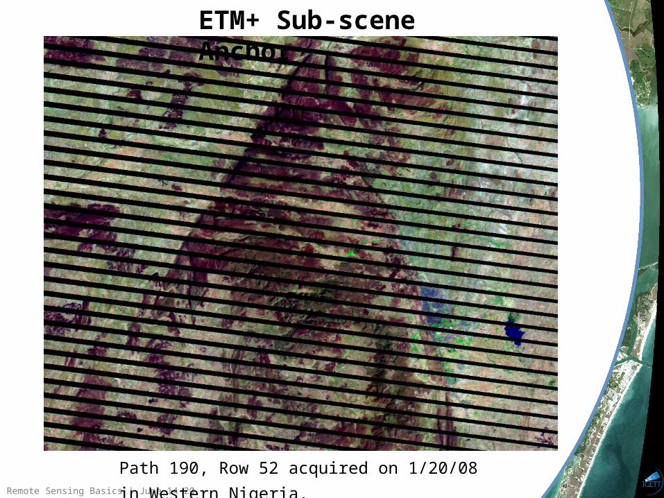
Path 190, Row 52 acquired on 1/20/08 in Western Nigeria.
ETM+ Sub-scene Anchor
Remote Sensing Basics | June 14-20, 2009
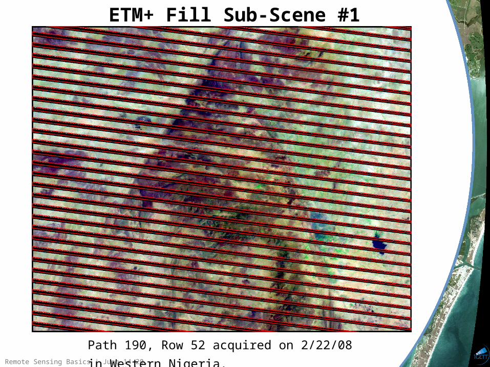
ETM+ Fill Sub-Scene #1
Path 190, Row 52 acquired on 2/22/08 in Western Nigeria.
Remote Sensing Basics | June 14-20, 2009
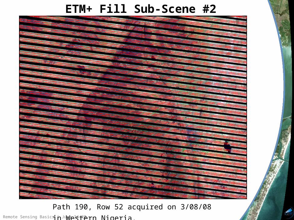
ETM+ Fill Sub-Scene #2
Path 190, Row 52 acquired on 3/08/08 in Western Nigeria.
Remote Sensing Basics | June 14-20, 2009
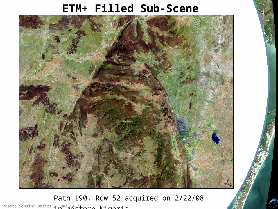
ETM+ Filled Sub-Scene
Path 190, Row 52 acquired on 2/22/08 in Western Nigeria.
Remote Sensing Basics | June 14-20, 2009
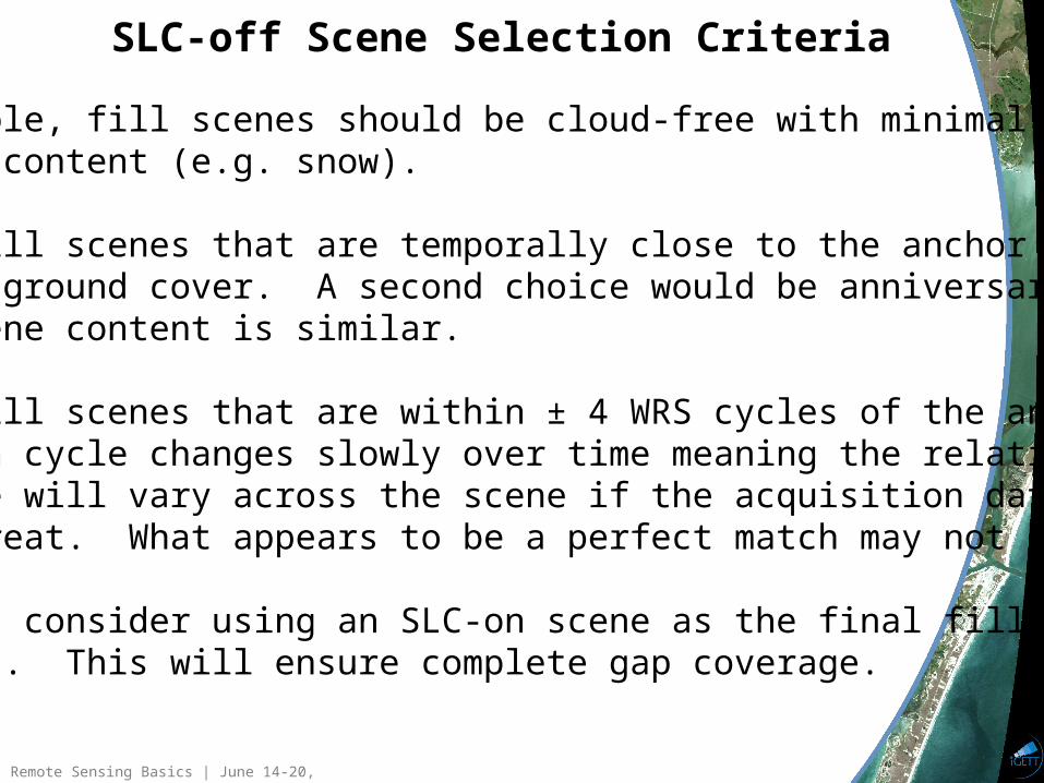
SLC-off Scene Selection Criteria
If possible, fill scenes should be cloud-free with minimal changesIn scene content (e.g. snow).
Choose fill scenes that are temporally close to the anchor to minimizechanging ground cover. A second choice would be anniversary sceneswhere scene content is similar.
Select fill scenes that are within ± 4 WRS cycles of the anchor. TheETM+ scan cycle changes slowly over time meaning the relative scangap phase will vary across the scene if the acquisition date intervalIs too great. What appears to be a perfect match may not be.
One might consider using an SLC-on scene as the final fillcomponent. This will ensure complete gap coverage.
![Lunar Reconnaissance Orbiter (LRO): Leading NASA’s Way ...2].pdf · Lunar Reconnaissance Orbiter (LRO): Leading NASA’s Way Back to the Moon ... nancy.n.jones@nasa.gov Jonas Dino](https://img.pdfslide.net/doc/110x75/5e703682e07d8403d07255d8/lunar-reconnaissance-orbiter-lro-leading-nasaas-way-2pdf-lunar-reconnaissance.jpg)