Embed Size (px)
Citation preview
1
REMOTE SOLAR-POWERED WATER PUMP
CONTROLLER
A Design Project Report
Presented to the School of Electrical and Computer Engineering of
Cornell University in Partial Fulfillment of the Requirements for the
Degree of Master of Engineering, Electrical and Computer
Engineering
Submitted by
Roland Krieger
Saisrinivasan Mohankumar
MEng Field Advisor: Bruce R. Land
Degree Date: May 2014
2
ABSTRACT
Master of Engineering Program
School of Electrical and Computer Engineering
Cornell University
Design Project Report
Project Title: Remote Solar-Powered Water Pump Controller
Authors: Roland Krieger
Saisrinivasan Mohankumar
Abstract:
Our goal is to design a remote solar-powered water pump controller. The system
consists of two parts: transmitter and receiver/pump end. The transmitter end consists
of a microcontroller, a float sensor, a 1.5W solar panel and an RF transmitter. The
receiver/pump end consists of a microcontroller, a water pump, hose, two 40 W solar
panels and an RF receiver. A steel frame is built to hold the solar panels, and a power
supply circuit is built to power the microcontrollers. In software development, the
microcontrollers will be programmed to enable communication over a 433 MHz channel.
The pump will draw water from the pump end to the transmitter end when there is
enough sunlight and the storage container is not full. The transmitter will communicate
the state of the container wirelessly to the receiver.
3
Executive Summary
The primary aim of the project is to design and deploy a remote, solar-powered waterpump controller to detect the level of water in a tank and pump in water from a remotesource like a pond as and when required. The water tank and the pond are separatedby about 100 meters and communicate wirelessly.The project consists of a transmitter unit and a receiver unit. The transmitter unit islocated near the water tank and receiver unit is located near the pond. The transmitterand receiver units are controlled by Atmel Atmega32 microcontroller units (MCUs).The transmitter unit consists of a microcontroller board for control, a float switch forchecking the level of water in the tank and a 433 MHz transmitter module for thewireless transmission of data. The entire module is powered by a 1.5W solar panelwhich gives a maximum output voltage of about 20V to power the microcontroller boardand transmitter.The receiver unit consists of a microcontroller board, a Shurflo diaphragm pump forpumping water, a 433MHz receiver module for wireless reception of data and a powertransistor circuit for controlling the motor. The entire setup and the motor is powered by2 large solar panels which are setup on a steel mount for rigidity. Furthermore, thecircuitry is enclosed in a steel case to protect it from adverse weather conditions.During operation, the microcontroller at the transmitter end senses the level of water inthe tank via the float switch. If the water level is low, the microcontroller transmits a‘pump on’ signal to the receiver through the RF transmitter using the 433 MHz wirelesslink. The MCU at the receiver end upon reception of this signal, sends a logic highsignal to the gate of a power transistor. This turns on the power transistor and causesthe motor to pump in water from the pond to the water tank.Upon design and testing, we got the transmitter and receiver subsystems to be workingseparately and communicating wirelessly. We were able to achieve a good range ofaround 80 metres with the RF wireless medium.The major challenges we faced were the accurate transmission of data and limitedrange of the wireless link. We approached these issues by increasing the baud ratefrom 400 to 4000 bps, and increasing the input voltage to the transmitter to about 12 V.

4
Individual Contribution
Roland Krieger completed the following parts of the design project
● Transmitter MCU Board development and soldering.● RF transmitter board development and soldering.● Software section for the transmitter.● Building receiver steel mount.● Introduction, Software, Results section and general formatting of the design
report.● Wireless link range tests● Pump rate tests
Saisrinivasan Mohankumar completed the following parts of the design project.● Receiver MCU Board development and soldering.● RF Receiver board development and soldering.● Software section for the Receiver.● Building receiver steel mount.● Abstract, Executive Summary, Design and Hardware section of the design
report.● Wireless link range tests● Pump rate tests
5
Table of Contents
1 Introduction………………………………………………………………….. 6
2 Requirements……………………………………………………………….. 8
2.1 System Level Requirements……………………………………………… 8
2.2 Transmitter Unit Requirements…………………………………………... 8
2.3 Receiver Unit Requirements……………………………………………… 8
2.4 Communication Protocol Requirements……………………………….. 8
2.5 Issues to be addressed……………………………………………………. 8
3 Design………………………………………………………………………… 10
3.1 Approach……………………………………………………………………... 10
3.2 Concept Diagram…………………………………………………………… 11
4 Hardware……………………………………………………………………... 12
4.1 Custom Prototype Board………………………………………………….. 12
4.2 Regulator Circuit……………………………………………………………. 13
4.3 TransmitterUnit……………………………………………………………...
14
4.4 Receiver Unit………………………………………………………………… 15
4.5 Motor Control Unit………………………………………………………….. 15
5 Software……………………………………………………………………… 17
5.1 TransmitterUnit……………………………………………………………...
17
5.2 Receiver Unit………………………………………………………………… 18
6 Results………………………………………………………………………... 20
7 References…………………………………………………………………… 23
8 Appendix……………………………………………………………………... 24
6
1. IntroductionFor small-scale farm owners living near water sources, it is useful to have an affordable
mechanism to obtain water from natural sources such as lakes and ponds to be used on
the farm. The aim of this project is to design such a mechanism for obtaining water from
natural sources automatically with limited human monitoring. We designed and built an
automated remote solar-powered water pump. This system should be able to draw
water from a pond or other natural source and transport it over a distance of about
100m to a water-storage container. The system consists of two parts linked in two ways.
The first link is the rubber hose which carries water from the source to the destination.
The second link is the radio link for communication between the two ends. We refer to
the subsystem with the water tank as the ‘transmitter end’, since it signals the other end
when to pump water. It will consist of: a microcontroller, a float sensor and a 433MHz
transceiver. The other subsystem will be called the receiver end. It will receive signals
detailing the state of the water tank at the transmitter. The receiver end will consist of:
two solar panels, a perforated steel frame, a microcontroller, a 433MHz receiver and a
water pump.
The rest of the documentation is organized as follows:
● Section 2: lists the requirements of the system and key issues to be addressed.
● Section 3: describes the design considerations of the system.
● Section 4: describes the hardware details and circuits of the project.
● Section 5: describes the software components involved in the project.
● Section 6: provides the results and conclusions drawn from the project.
● Section 7: lists the various sources of reference we used for the completion of
the project.

7
● Section 8: contains the various appendices like code availability.
8
2. RequirementsThis section details the requirements to be met by the Remote Solar-Powered WaterPump.2.1 System Level RequirementsSYS 1. The maximum cost of the system shall be less than $500SYS 2. The system shall run on solar energySYS 3. The system shall withstand rain/snowSYS 4. The system shall be reliable and safeSYS 5. The system shall measure the water level in tankSYS 6. The system shall communicate from transmitter to receiverSYS 7. The system shall be eco- friendlySYS 8. The system parts can be easily changed2.2 Transmitter Unit RequirementsTX 1. The transmitter unit shall measure the level of water in the tank.TX 2. The transmitter unit shall be powered by solar energy.TX 3. The transmitter unit shall consume limited power.TX 4. The transmitter unit shall be easily replaceable.TX 5. The transmitter unit shall send pump on/off signals to the receiver.2.3 Receiver Unit RequirementsRX 1. The receiver unit shall pump in water to the tank.RX 2. The receiver unit shall be powered by solar energy.RX 3. The receiver unit shall be easily replaceable.RX 4. The receiver unit shall be able to withstand rain/snow.2.4 Communication Protocol RequirementsCOM 1. The protocol shall be reliable.COM 2. The protocol shall have required medium range of about 100m.COM 3. The protocol should be able to withstand interference.2.5 Issues To Be Addressed: The issues are enumerated below and explained indetail:
1. Resistance to Harsh WeatherThe primary issue is to build a steady steel mount to hold the solar panels and protectthe control circuitry from adverse weather conditions like snow and rain. The steel frameis high enough and the circuitry will be enclosed in a steel case so when it rains orsnows, the electronics don’t get affected.
2. Reliable Communication between two endsA suitable wireless mode for communication between the two parts should be selected
as the two ends may be separated by forested region so the signals should not be lost.

9
3. Life-span of the systemThe receiver end should be able to last for several years. The solar panels will be ableto operate for over 10 years. The water pump is estimated to last at least 3 years. Thismeans for 3 years, the owner should ideally not have to do any work at the receiverend.
10
3 Design3.1 Approach3.1.1. CostThe cost factor of the project was confined to most of the hardware. The major cost ofthe project were the two big solar panels and the water pump. The 40W solar panelswere roughly $100 each and the diaphragm pump was around $75. The custommicrocontroller board was built using an Atmega32 microcontroller which was not veryexpensive and also the transmitter and receiver circuitry were soldered using readilyavailable parts in the lab.3.1.2. RobustnessThe primary need of the system was to be able to withstand varying weather conditionsincluding rain, wind and snow. To take care of this need, we decided to build a verystable and strong steel mount for holding the solar panels firmly over the ground. Theelevated frame also helps in ensuring that the solar panels have more access tosunlight than at the ground level. The elevation also helps to protect the microcontrollerreceiver circuitry which is placed under the solar panels from rain as well as snowaccumulation on the ground during winter.3.1.3 Range
Another important consideration to be made before designing the project was to makesure that considerable range of operation would be possible using the wirelesstransmission. As the distance of separation of the pond and water tank in our case wasroughly 80 to 100m, we decided to use the RCR and RCT 433 MHz transceivermodules because they operate on low power and also give the required range of amaximum 100 metres. Also, since the device would be deployed in a rural farm area, itis not expected that there would be many interference sources. However, the use ofsynchronization and start characters, as well as the repeated transmission of packetsshould enable the system function reasonably well under moderate interference.3.1.4. Reliability
Reliability of the system to automate the pumping process is very essential to thisproject. It was one of the primary motives because the entire process has to be reliableand automated. The system works reliably without any special intervention of the userand the entire pumping procedure works automatically. As a safety precaution, in casethe transmitter somehow fails to transmit after the tank has been full, the receiver isprogrammed to turn off the pump 3 minutes after the last ‘pump on’ signal is received.This avoids overflow of the tank when the receiver does not get a ‘pump off’ signal at all.
11
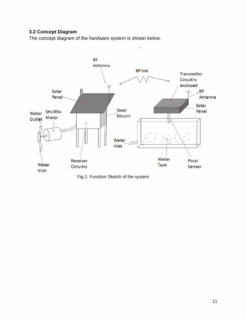
3.2 Concept DiagramThe concept diagram of the hardware system is shown below.
Fig.1: Function Sketch of the system
12
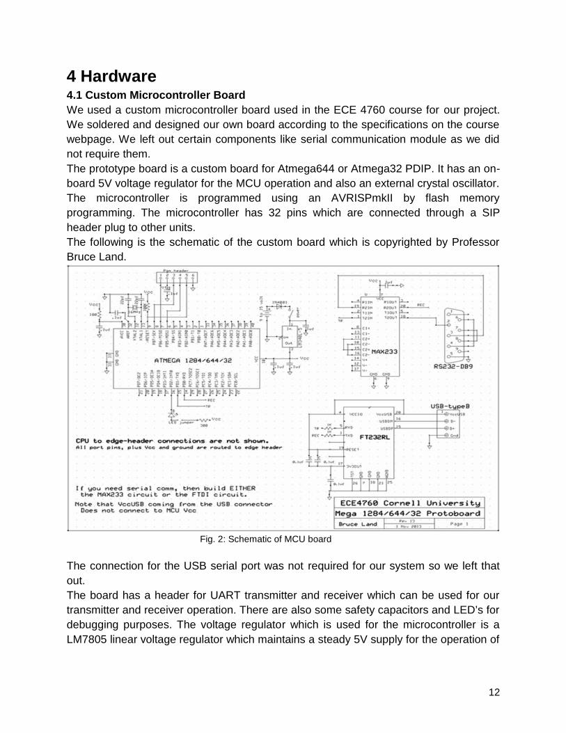
4 Hardware4.1 Custom Microcontroller BoardWe used a custom microcontroller board used in the ECE 4760 course for our project.We soldered and designed our own board according to the specifications on the coursewebpage. We left out certain components like serial communication module as we didnot require them.The prototype board is a custom board for Atmega644 or Atmega32 PDIP. It has an on-board 5V voltage regulator for the MCU operation and also an external crystal oscillator.The microcontroller is programmed using an AVRISPmkII by flash memoryprogramming. The microcontroller has 32 pins which are connected through a SIPheader plug to other units.The following is the schematic of the custom board which is copyrighted by ProfessorBruce Land.
Fig. 2: Schematic of MCU board
The connection for the USB serial port was not required for our system so we left thatout.The board has a header for UART transmitter and receiver which can be used for ourtransmitter and receiver operation. There are also some safety capacitors and LED’s fordebugging purposes. The voltage regulator which is used for the microcontroller is aLM7805 linear voltage regulator which maintains a steady 5V supply for the operation of
13
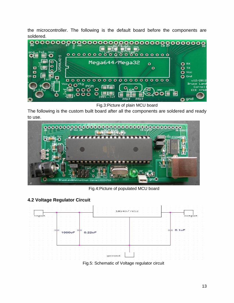
the microcontroller. The following is the default board before the components aresoldered.
Fig.3:Picture of plain MCU boardThe following is the custom built board after all the components are soldered and readyto use.
Fig.4:Picture of populated MCU board
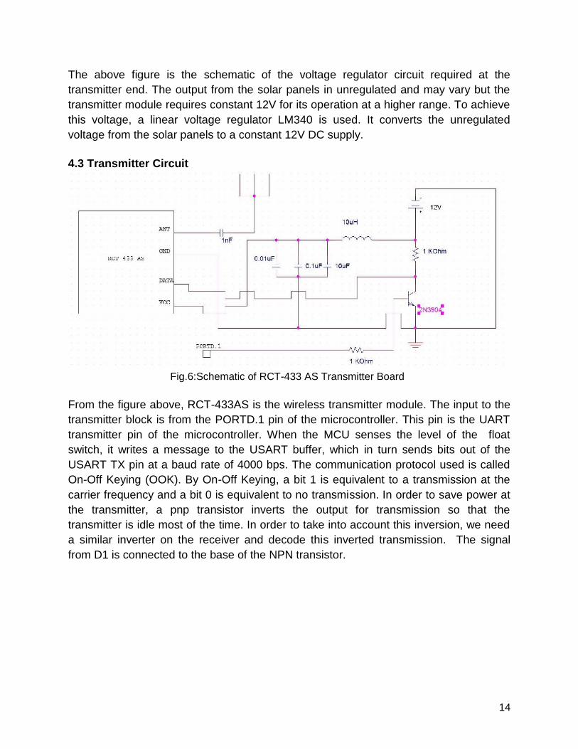
4.2 Voltage Regulator Circuit
Fig.5: Schematic of Voltage regulator circuit
14
The above figure is the schematic of the voltage regulator circuit required at thetransmitter end. The output from the solar panels in unregulated and may vary but thetransmitter module requires constant 12V for its operation at a higher range. To achievethis voltage, a linear voltage regulator LM340 is used. It converts the unregulatedvoltage from the solar panels to a constant 12V DC supply.
4.3 Transmitter Circuit
Fig.6:Schematic of RCT-433 AS Transmitter Board
From the figure above, RCT-433AS is the wireless transmitter module. The input to thetransmitter block is from the PORTD.1 pin of the microcontroller. This pin is the UARTtransmitter pin of the microcontroller. When the MCU senses the level of the floatswitch, it writes a message to the USART buffer, which in turn sends bits out of theUSART TX pin at a baud rate of 4000 bps. The communication protocol used is calledOn-Off Keying (OOK). By On-Off Keying, a bit 1 is equivalent to a transmission at thecarrier frequency and a bit 0 is equivalent to no transmission. In order to save power atthe transmitter, a pnp transistor inverts the output for transmission so that thetransmitter is idle most of the time. In order to take into account this inversion, we needa similar inverter on the receiver and decode this inverted transmission. The signalfrom D1 is connected to the base of the NPN transistor.
15
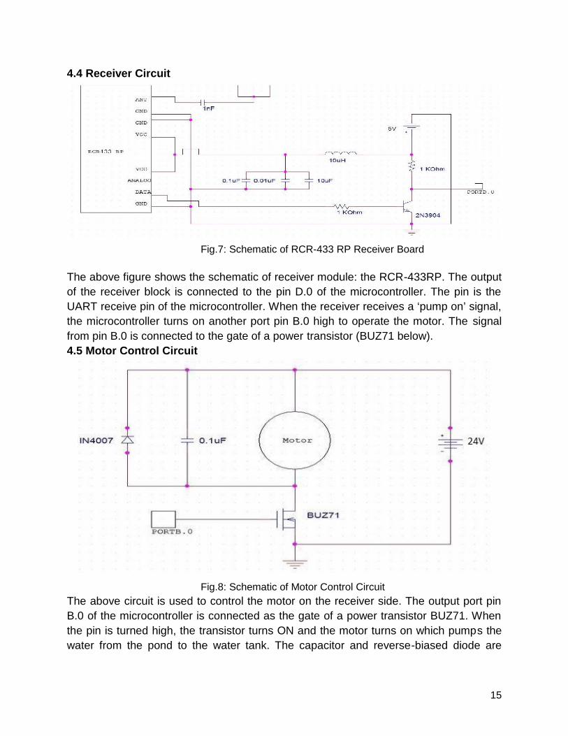
4.4 Receiver Circuit
Fig.7: Schematic of RCR-433 RP Receiver Board
The above figure shows the schematic of receiver module: the RCR-433RP. The outputof the receiver block is connected to the pin D.0 of the microcontroller. The pin is theUART receive pin of the microcontroller. When the receiver receives a ‘pump on’ signal,the microcontroller turns on another port pin B.0 high to operate the motor. The signalfrom pin B.0 is connected to the gate of a power transistor (BUZ71 below).4.5 Motor Control Circuit
Fig.8: Schematic of Motor Control CircuitThe above circuit is used to control the motor on the receiver side. The output port pinB.0 of the microcontroller is connected as the gate of a power transistor BUZ71. Whenthe pin is turned high, the transistor turns ON and the motor turns on which pumps thewater from the pond to the water tank. The capacitor and reverse-biased diode are

16
connected in parallel with the motor to avoid inductive spikes which might damage theMCU.
17
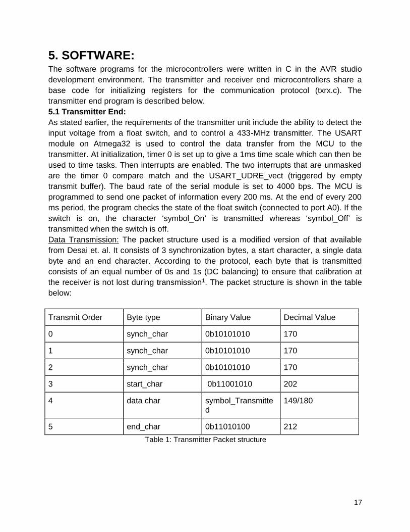
5. SOFTWARE:The software programs for the microcontrollers were written in C in the AVR studiodevelopment environment. The transmitter and receiver end microcontrollers share abase code for initializing registers for the communication protocol (txrx.c). Thetransmitter end program is described below.5.1 Transmitter End:As stated earlier, the requirements of the transmitter unit include the ability to detect theinput voltage from a float switch, and to control a 433-MHz transmitter. The USARTmodule on Atmega32 is used to control the data transfer from the MCU to thetransmitter. At initialization, timer 0 is set up to give a 1ms time scale which can then beused to time tasks. Then interrupts are enabled. The two interrupts that are unmaskedare the timer 0 compare match and the USART_UDRE_vect (triggered by emptytransmit buffer). The baud rate of the serial module is set to 4000 bps. The MCU isprogrammed to send one packet of information every 200 ms. At the end of every 200ms period, the program checks the state of the float switch (connected to port A0). If theswitch is on, the character ‘symbol_On’ is transmitted whereas ‘symbol_Off’ istransmitted when the switch is off.Data Transmission: The packet structure used is a modified version of that availablefrom Desai et. al. It consists of 3 synchronization bytes, a start character, a single databyte and an end character. According to the protocol, each byte that is transmittedconsists of an equal number of 0s and 1s (DC balancing) to ensure that calibration atthe receiver is not lost during transmission1. The packet structure is shown in the tablebelow:
Transmit Order Byte type Binary Value Decimal Value
0 synch_char 0b10101010 170
1 synch_char 0b10101010 170
2 synch_char 0b10101010 170
3 start_char 0b11001010 202
4 data char symbol_Transmitted
149/180
5 end_char 0b11010100 212Table 1: Transmitter Packet structure
18
The data symbol that is transmitted is symbol_Off (149) and symbol_On (180). Onecharacter is loaded into the transmit buffer at a time when the empty transmit bufferinterrupt occurs (USART_UDRE_vect). The USART module then outputs the bits out ofPIN D.1 which is the transmit pin. This pin is connected to the base of an npn transistorto turn on or off the transmitter. The benefit of the symbols used above is that theminimum Hamming distance between any two symbols is 2, which means that at leasttwo bit flips are required before one symbol is wrongfully decoded as another1.5.2 Receiver End:The program running on the microcontroller at the receiver should be able to detect the
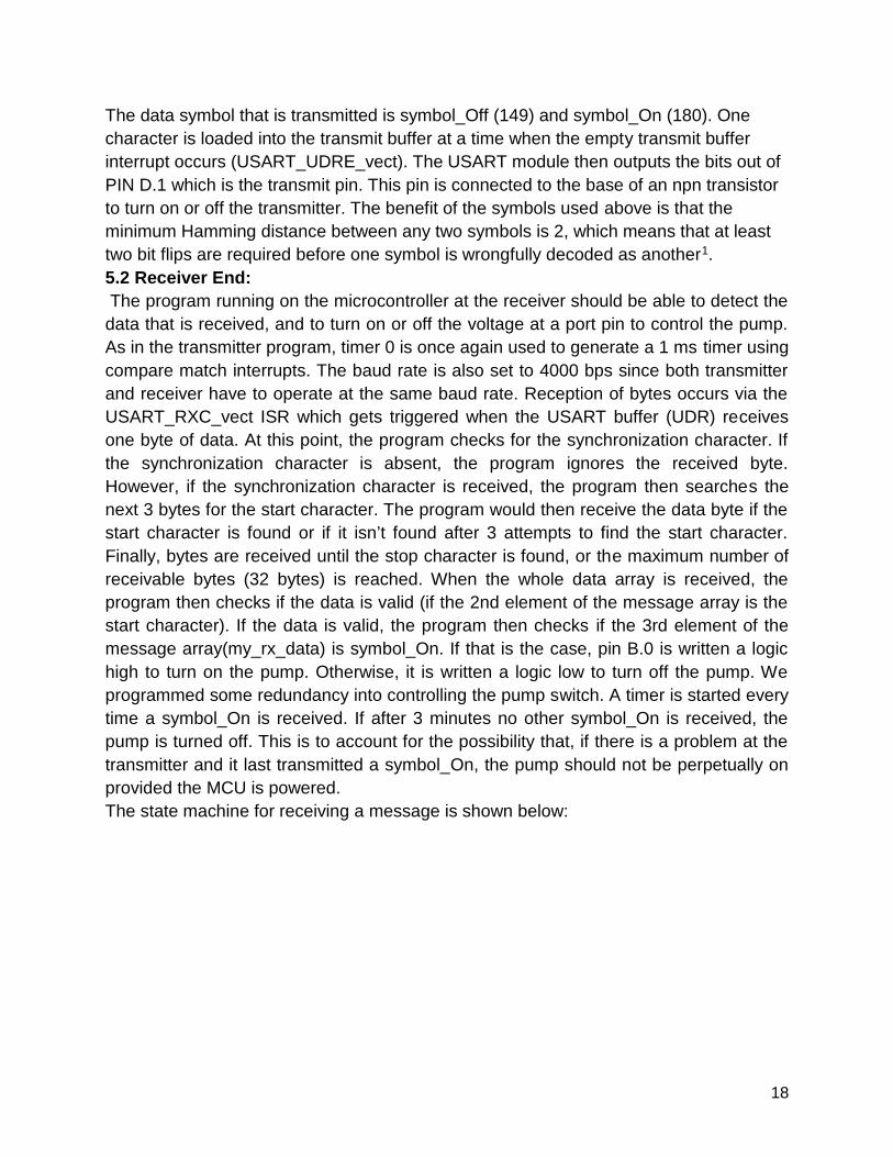
data that is received, and to turn on or off the voltage at a port pin to control the pump.As in the transmitter program, timer 0 is once again used to generate a 1 ms timer usingcompare match interrupts. The baud rate is also set to 4000 bps since both transmitterand receiver have to operate at the same baud rate. Reception of bytes occurs via theUSART_RXC_vect ISR which gets triggered when the USART buffer (UDR) receivesone byte of data. At this point, the program checks for the synchronization character. Ifthe synchronization character is absent, the program ignores the received byte.However, if the synchronization character is received, the program then searches thenext 3 bytes for the start character. The program would then receive the data byte if thestart character is found or if it isn’t found after 3 attempts to find the start character.Finally, bytes are received until the stop character is found, or the maximum number ofreceivable bytes (32 bytes) is reached. When the whole data array is received, theprogram then checks if the data is valid (if the 2nd element of the message array is thestart character). If the data is valid, the program then checks if the 3rd element of themessage array(my_rx_data) is symbol_On. If that is the case, pin B.0 is written a logichigh to turn on the pump. Otherwise, it is written a logic low to turn off the pump. Weprogrammed some redundancy into controlling the pump switch. A timer is started everytime a symbol_On is received. If after 3 minutes no other symbol_On is received, thepump is turned off. This is to account for the possibility that, if there is a problem at thetransmitter and it last transmitted a symbol_On, the pump should not be perpetually onprovided the MCU is powered.The state machine for receiving a message is shown below:
19
Fig.9: State diagram of receiver
20
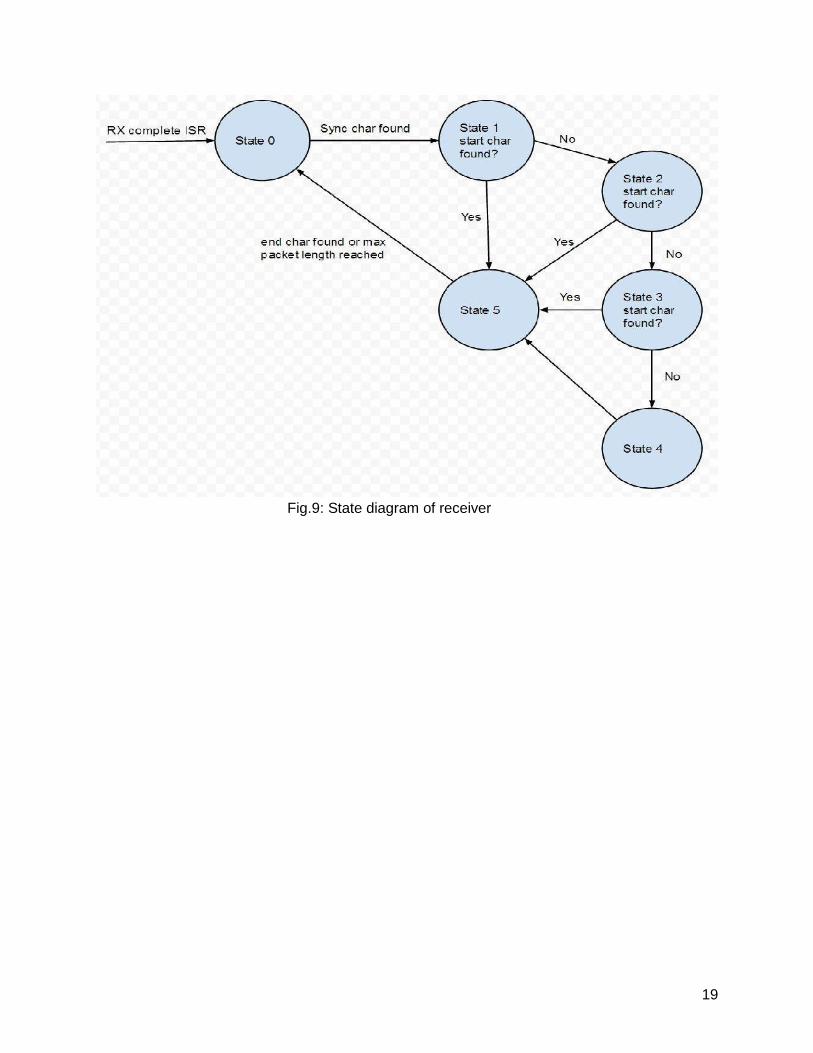
6. RESULTS6.1 Accuracy and reliabilityThe subsystems of this project have been independently tested and are working. Thefirst major test is the range test of the 433 MHz wireless link. Indoor and outdoor testingproduced a range of about 80 meters. The indoor test was performed at opposite endsof Duffield Atrium, which is quite spacious but still has some reflecting surfaces likewalls and tables. The outdoor test was performed across the engineering quad, with thetransmitter at the top of the staircase leading to Duffield Hall and the receiver at theentrance to the engineering library. It was mostly open space, with only a few trees inthe vicinity of the transmitter and receiver. This range has been achieved withoutsophisticated antenna design (impedance matching and different antenna topologies).We used a quarter wavelength wire (17 cm) at the transmitter. At the receiver end, wefirst used a 17-cm wire as an antenna, and then a 17-cm tape measure. We found that,even though both cases gave the same range, a receiver antenna made out of tapemeasure received signals more often than one made out of wire. The downside of usingtape measure as an antenna is that it is too heavy and needs a rigid base which ispresent at the receiver because of the steel case enclosing the receiver circuitry. Withbetter antenna design, it is possible to increase the range above 80 meters.The pump at the receiver will pump at varying speeds from 24V to about 3.5V. Thus,when it becomes reasonably cloudy, the pump is still expected to work albeit at slowerspeeds.A plot of pump rate at selected input voltages according to our observation is shownbelow:
Fig 10. Pump rate versus input voltage
21
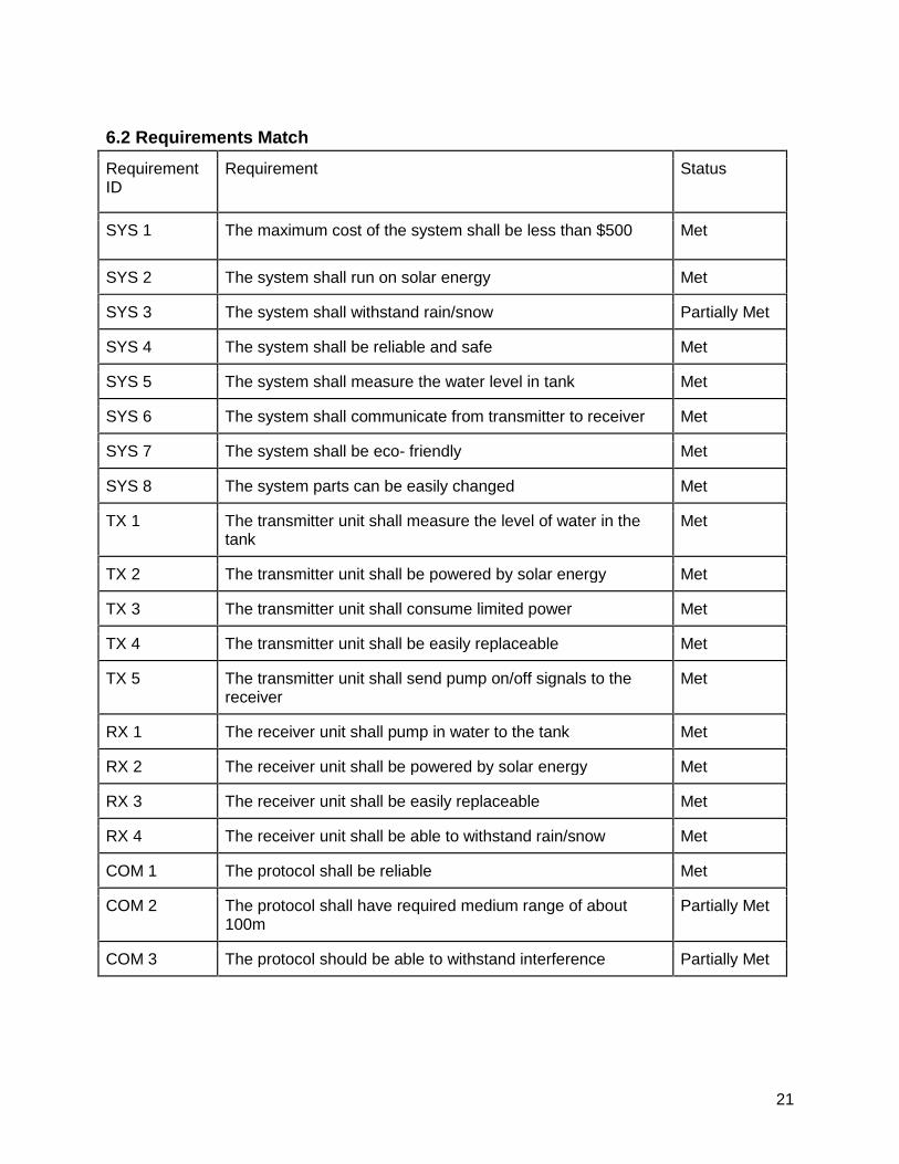
6.2 Requirements MatchRequirementID
Requirement Status
SYS 1 The maximum cost of the system shall be less than $500 Met
SYS 2 The system shall run on solar energy Met
SYS 3 The system shall withstand rain/snow Partially Met
SYS 4 The system shall be reliable and safe Met
SYS 5 The system shall measure the water level in tank Met
SYS 6 The system shall communicate from transmitter to receiver Met
SYS 7 The system shall be eco- friendly Met
SYS 8 The system parts can be easily changed Met
TX 1 The transmitter unit shall measure the level of water in thetank
Met
TX 2 The transmitter unit shall be powered by solar energy Met
TX 3 The transmitter unit shall consume limited power Met
TX 4 The transmitter unit shall be easily replaceable Met
TX 5 The transmitter unit shall send pump on/off signals to thereceiver
Met
RX 1 The receiver unit shall pump in water to the tank Met
RX 2 The receiver unit shall be powered by solar energy Met
RX 3 The receiver unit shall be easily replaceable Met
RX 4 The receiver unit shall be able to withstand rain/snow Met
COM 1 The protocol shall be reliable Met
COM 2 The protocol shall have required medium range of about100m
Partially Met
COM 3 The protocol should be able to withstand interference Partially Met
22
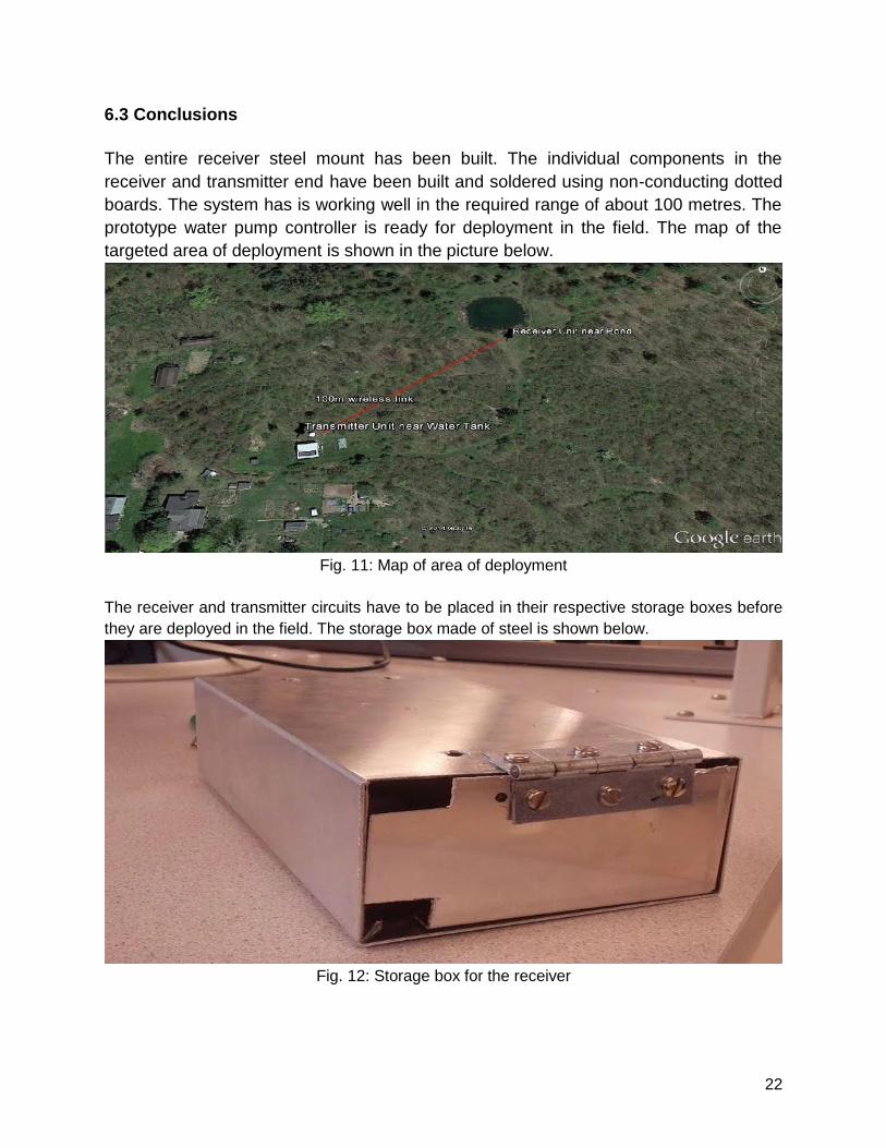
6.3 Conclusions
The entire receiver steel mount has been built. The individual components in thereceiver and transmitter end have been built and soldered using non-conducting dottedboards. The system has is working well in the required range of about 100 metres. Theprototype water pump controller is ready for deployment in the field. The map of thetargeted area of deployment is shown in the picture below.
Fig. 11: Map of area of deployment
The receiver and transmitter circuits have to be placed in their respective storage boxes beforethey are deployed in the field. The storage box made of steel is shown below.
Fig. 12: Storage box for the receiver
23
7. REFERENCES:1. Desai, M.Wireless Transmit and Receive Projecthttp://people.ece.cornell.edu/land/courses/eceprojectsland/STUDENTPROJ/2005to2006/mpd25/report.html
2. Mega 644 Prototype boardhttp://people.ece.cornell.edu/land/PROJECTS/ProtoBoard476/
3. Report Guidelinehttp://people.ece.cornell.edu/land/courses/eceprojectsland/STUDENTPROJ/2010to2011/arv44_zx52/arv44_report_201105200944.pdf
24
8. APPENDIX
8.1 Code
Code available upon request from the authors.
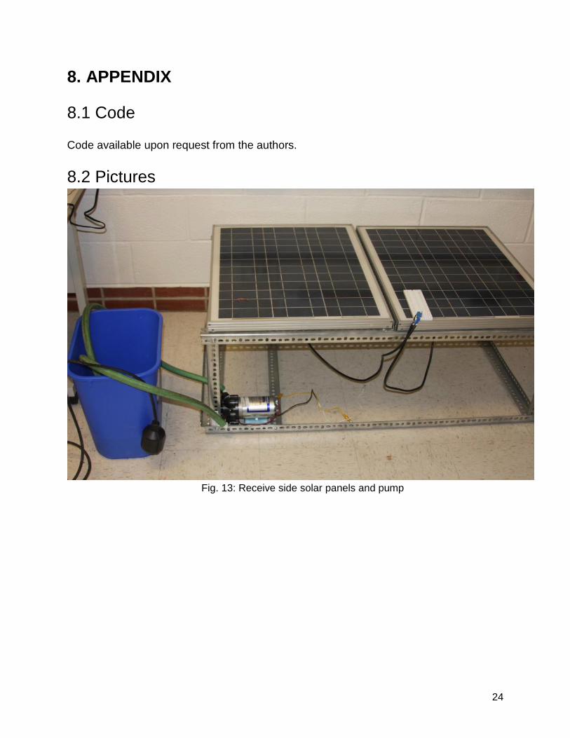
8.2 Pictures
Fig. 13: Receive side solar panels and pump
25
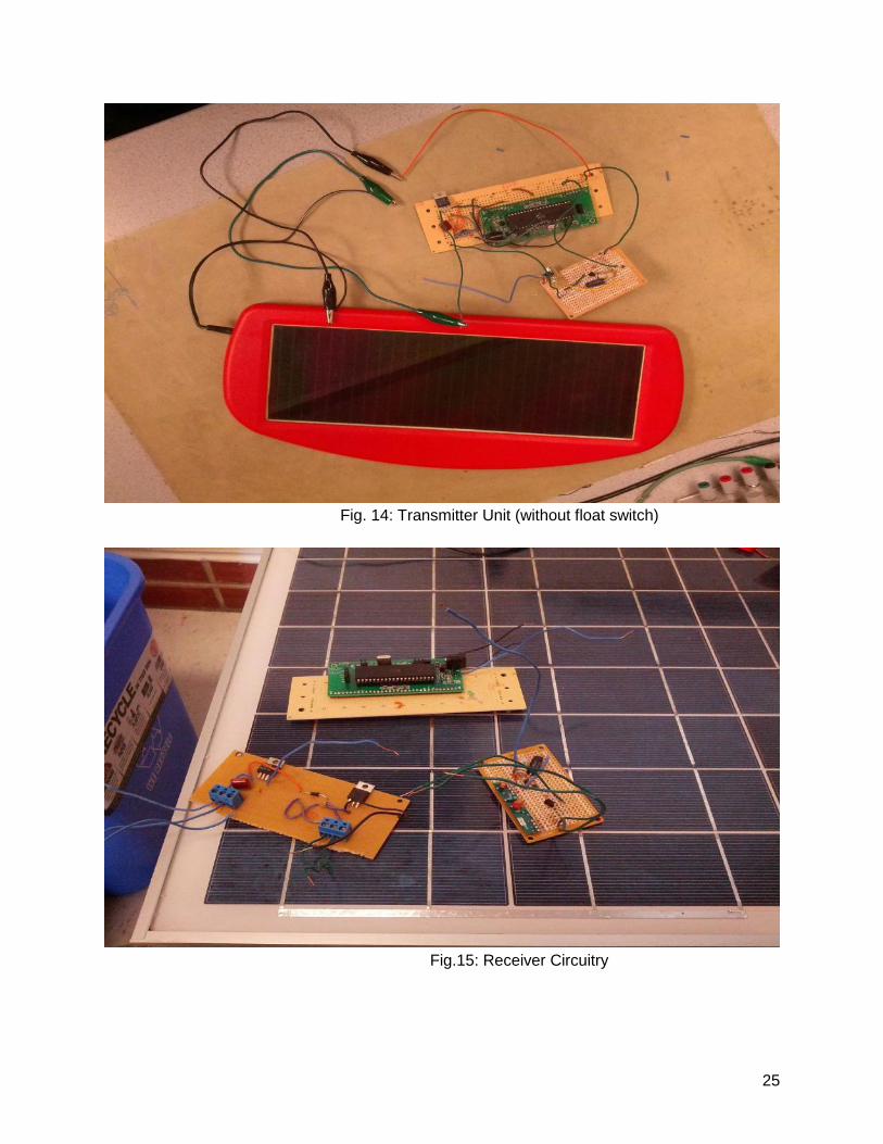
Fig. 14: Transmitter Unit (without float switch)
Fig.15: Receiver Circuitry
26
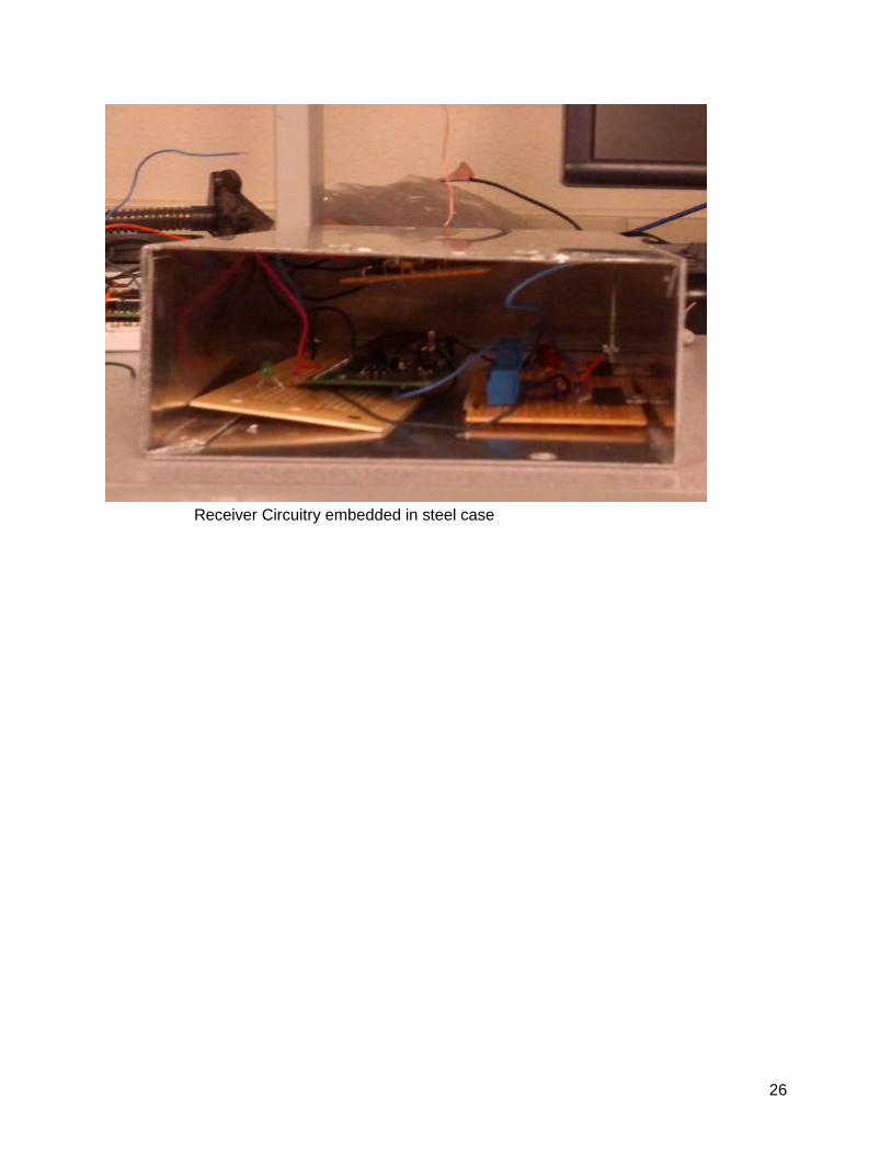
Receiver Circuitry embedded in steel case