Embed Size (px)
Citation preview
REMOVAL OF PHREATIC WATER EXCESS OF THE BASEMENT CONSTRUCTIONS LOCATED ON SLOPING LANDS
Oprea RADU1
E-mail: [email protected]
Abstract In order to insure a high stability and a normal exploitation of a building, both the land and the foundation must fulfill certain conditions, that is the foundation has to be strong and dry. The underground waters are mostly guilty for the problems and damages caused to the civil and industrial constructions, both in the construction’s execution phase and during their utilization and exploitation. In this paper, we present a method for removing water excess deriving from the underground water, but also of the rain water coming from the roof of the building and from the sidewalks. By executing an appropriate drainage for the basement constructions, we insure water removal, the hydrostatic pressure exercised on the walls is reduced, the formation of mildew and dampness is avoided, which allows an appropriate use of the basement spaces. Key words: excessive humidity, building drainage, drainage tube, filtering prism, geotextile
1 University of Agricultural Sciences and Veterinary Medicine, Iaşi
Water infiltration into the basement walls of buildings is a permanent issue to be solved by architects and designers. If the water is not removed from the base of foundations critical problems cam appear in the rooms placed at ground level, the infiltrations affecting also the resistance walls of the building (Radulescu et al., 2010). Moreover water accumulation around the buildings makes the soil heavier to the detriment of walls that have sometimes to bear a double pressure compared to the normal situations (Alexandrescu, I., 2010). Such kind of issues emerges due to a lack of measures of water elimination, to improper drains or due to wrong methods of sealing the walls to water infiltration.
MATERIAL AND METHOD
The surveys were performed to a building
with basement (fig. 1) located in Horodniceni commune, Suceava county.
Figure 1 Placement of building
The construction is placed on a land with an average 22% slope, a slope affected by an excess of humidity coming out from heavy rainfalls and from a 1-2 meter depth ground water table.
In order to carry out the perimetral drainage of the building it was adapted a method derived from the elimination of water excess of the farm fields made up of absorbing drainages and of filtering material columns.
In case of the underground drainage associated with land modeling in ridge bands from the farm fields, the literature in the field recommends for improving the collecting conditions of absorbing drainages placed under ditches to erect columns of filtering materials from the drainage level to ditch level. The insertion of filtering columns, in the case of farm fields allows the increase of column size and reduction of collection-discharge network.
An economic solution of modeling system of the land in band ridges consists of carrying out water collection from ditches with collecting drainages, placed perpendicular on bands at large distances (about 75 m), the discharge of each ditch into the collecting drainage being made through a prism of granular filtering material. The prism erected at the level of drainage until the land surface makes the hydraulic connection ditch-drain, this being protected by clogging up with a geotextile layer (Barbu Floru, 1986).
RESULTS AND DISCUSSIONS
In order to eliminate the excess of water and
to provide the usage of construction basement in good conditions, it was executed in the first stage a
169
Lucrări ştiinţifice - vol. 54, Nr. 2/2011, seria Agronomie
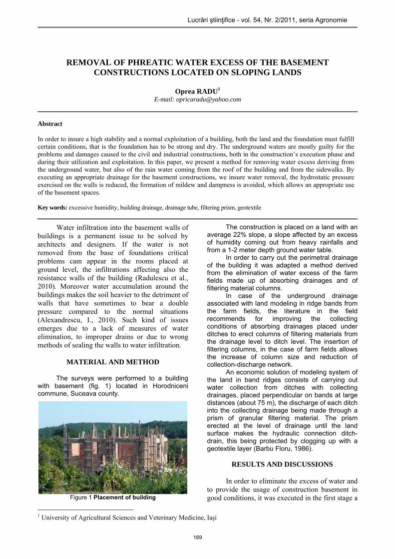
perimetral drainage to the building placed at the level of foundation base (fig. 2).
The perimetral drainage consisted in execution of a ditch at the level of foundation base
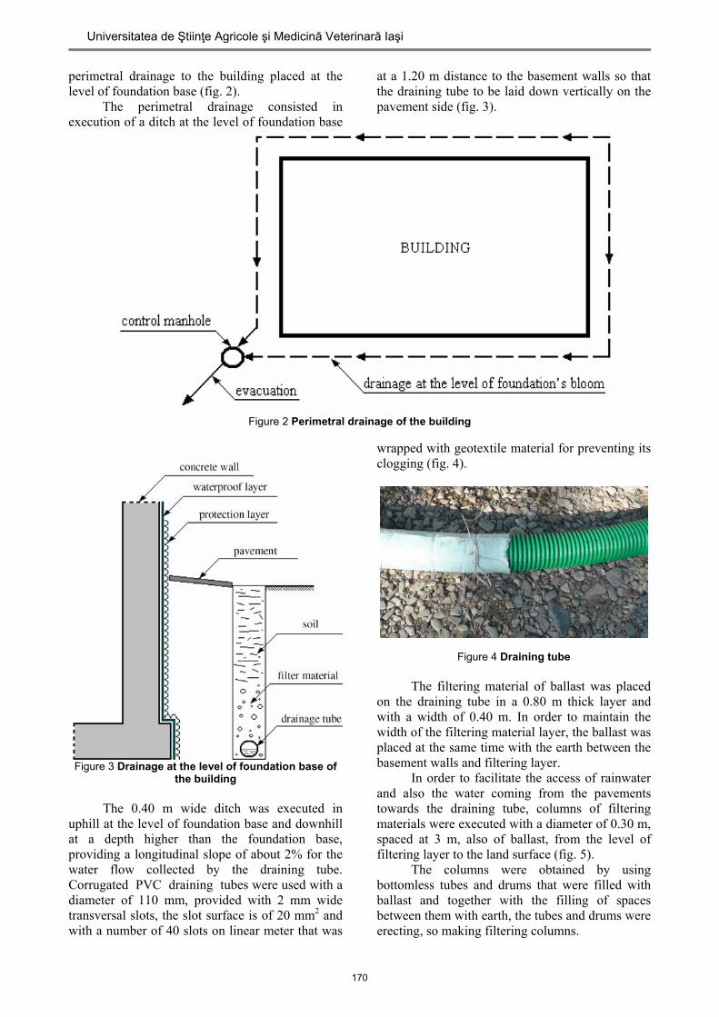
at a 1.20 m distance to the basement walls so that the draining tube to be laid down vertically on the pavement side (fig. 3).
Figure 2 Perimetral drainage of the building
Figure 3 Drainage at the level of foundation base of
the building The 0.40 m wide ditch was executed in
uphill at the level of foundation base and downhill at a depth higher than the foundation base, providing a longitudinal slope of about 2% for the water flow collected by the draining tube. Corrugated PVC draining tubes were used with a diameter of 110 mm, provided with 2 mm wide transversal slots, the slot surface is of 20 mm2 and with a number of 40 slots on linear meter that was
wrapped with geotextile material for preventing its clogging (fig. 4).
Figure 4 Draining tube The filtering material of ballast was placed
on the draining tube in a 0.80 m thick layer and with a width of 0.40 m. In order to maintain the width of the filtering material layer, the ballast was placed at the same time with the earth between the basement walls and filtering layer.
In order to facilitate the access of rainwater and also the water coming from the pavements towards the draining tube, columns of filtering materials were executed with a diameter of 0.30 m, spaced at 3 m, also of ballast, from the level of filtering layer to the land surface (fig. 5).
The columns were obtained by using bottomless tubes and drums that were filled with ballast and together with the filling of spaces between them with earth, the tubes and drums were erecting, so making filtering columns.
170
Universitatea de Ştiinţe Agricole şi Medicină Veterinară Iaşi
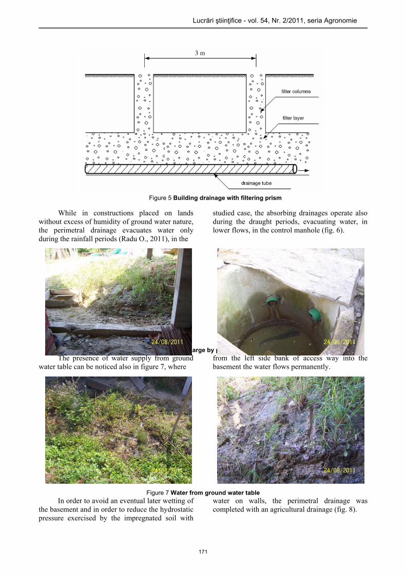
Figure 5 Building drainage with filtering prism
While in constructions placed on lands
without excess of humidity of ground water nature, the perimetral drainage evacuates water only during the rainfall periods (Radu O., 2011), in the
studied case, the absorbing drainages operate also during the draught periods, evacuating water, in lower flows, in the control manhole (fig. 6).
Figure 6 Water discharge by perimetral drainage The presence of water supply from ground
water table can be noticed also in figure 7, where
from the left side bank of access way into the basement the water flows permanently.
Figure 7 Water from ground water table In order to avoid an eventual later wetting of
the basement and in order to reduce the hydrostatic pressure exercised by the impregnated soil with
water on walls, the perimetral drainage was completed with an agricultural drainage (fig. 8).
171
Lucrări ştiinţifice - vol. 54, Nr. 2/2011, seria Agronomie
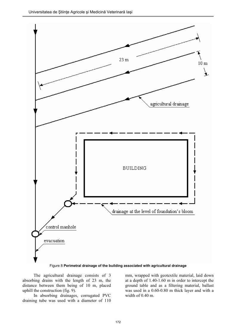
Figure 8 Perimetral drainage of the building associated with agricultural drainage The agricultural drainage consists of 3
absorbing drains with the length of 23 m, the distance between them being of 10 m, placed uphill the construction (fig. 9).
In absorbing drainages, corrugated PVC draining tube was used with a diameter of 110
mm, wrapped with geotextile material, laid down at a depth of 1.40-1.60 m in order to intercept the ground table and as a filtering material, ballast was used in a 0.60-0.80 m thick layer and with a width of 0.40 m.
172
Universitatea de Ştiinţe Agricole şi Medicină Veterinară Iaşi
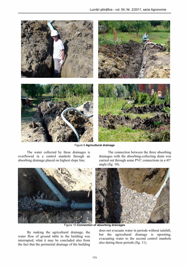
Figure 9 Agricultural drainage
The water collected by these drainages is overflowed in a control manhole through an absorbing drainage placed on highest slope line.
The connection between the three absorbing drainages with the absorbing-collecting drain was carried out through some PVC connections in a 45° angle (fig. 10).
Figure 10 Connection of absorbing drainages
By making the agricultural drainage, the water flow of ground table to the building was interrupted, what it may be concluded also from the fact that the perimetral drainage of the building
does not evacuate water in periods without rainfall, but the agricultural drainage is operating, evacuating water to the second control manhole also during these periods (fig. 11).
173
Lucrări ştiinţifice - vol. 54, Nr. 2/2011, seria Agronomie
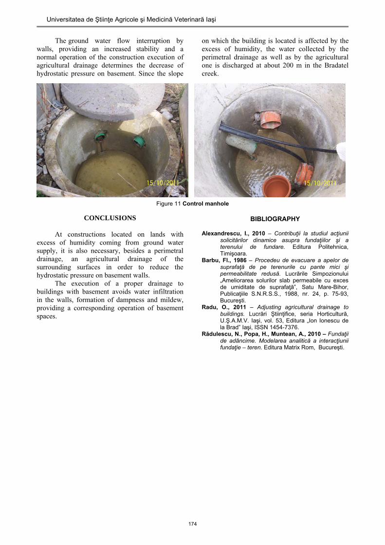
The ground water flow interruption by walls, providing an increased stability and a normal operation of the construction execution of agricultural drainage determines the decrease of hydrostatic pressure on basement. Since the slope
on which the building is located is affected by the excess of humidity, the water collected by the perimetral drainage as well as by the agricultural one is discharged at about 200 m in the Bradatel creek.
Figure 11 Control manhole
CONCLUSIONS
At constructions located on lands with excess of humidity coming from ground water supply, it is also necessary, besides a perimetral drainage, an agricultural drainage of the surrounding surfaces in order to reduce the hydrostatic pressure on basement walls.
The execution of a proper drainage to buildings with basement avoids water infiltration in the walls, formation of dampness and mildew, providing a corresponding operation of basement spaces.
BIBLIOGRAPHY
Alexandrescu, I., 2010 – Contribuţii la studiul acţiunii
solicitărilor dinamice asupra fundaţiilor şi a terenului de fundare. Editura Politehnica, Timişoara.
Barbu, Fl., 1986 – Procedeu de evacuare a apelor de suprafaţă de pe terenurile cu pante mici şi permeabilitate redusă. Lucrările Simpozionului „Ameliorarea solurilor slab permeabile cu exces de umiditate de suprafaţă”, Satu Mare-Bihor, Publicaţiile S.N.R.S.S., 1988, nr. 24, p. 75-93, Bucureşti.
Radu, O., 2011 – Adjusting agricultural drainage to buildings. Lucrări Ştiinţifice, seria Horticultură, U.Ş.A.M.V. Iaşi, vol. 53, Editura „Ion Ionescu de la Brad” Iaşi, ISSN 1454-7376.
Rădulescu, N., Popa, H., Muntean, A., 2010 – Fundaţii de adâncime. Modelarea analitică a interacţiunii fundaţie – teren. Editura Matrix Rom, Bucureşti.
174
Universitatea de Ştiinţe Agricole şi Medicină Veterinară Iaşi