Embed Size (px)
Citation preview
REMOVALPROCEDURES E R V I C E M A N U A L
Outdoor Unit
Non-inverter
Pair Type
2.5/3.5 kW Class9000/12000 Btu/h Class
Si011083
Service ManualRemoval Procedure
Outdoor Unit
Cooling OnlyR25GV1G6R35GV1G6
RE09LV2SRE12LV2S
Si011083
Removal Procedure 1
Table of Contents
1. Removal of Outer Panels / Fan Motor.....................................................22. Removal of Electrical Components ASSY ..............................................83. Removal of Sound Blanket......................................................................94. Removal of Compressor .......................................................................10
Note: The illustrations may be slightly different depending on the model.
Removal of Outer Panels / Fan Motor Si011083
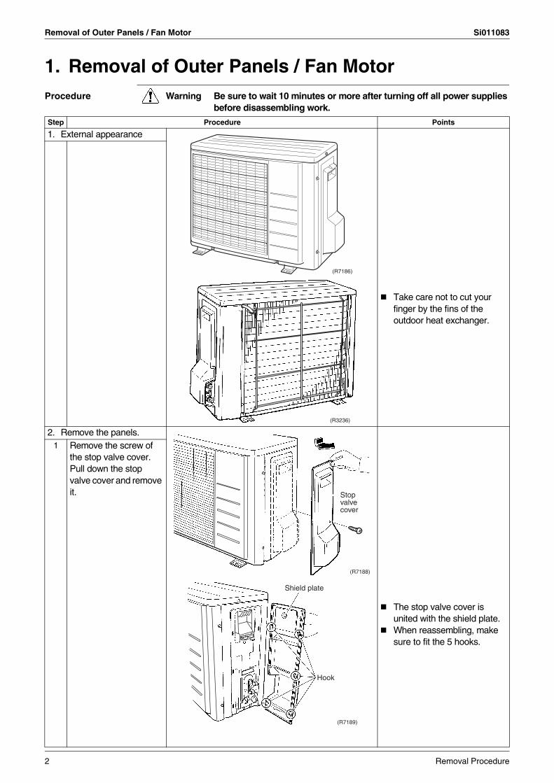
1. Removal of Outer Panels / Fan MotorProcedure Warning Be sure to wait 10 minutes or more after turning off all power supplies
before disassembling work.
Step Procedure Points
1. External appearance
Take care not to cut your finger by the fins of the outdoor heat exchanger.
2. Remove the panels.
The stop valve cover is united with the shield plate.When reassembling, make sure to fit the 5 hooks.
1 Remove the screw of the stop valve cover.Pull down the stop valve cover and remove it.
DAIKININVERTER
(R7186)
(R3236)
Stop valve cover
(R7188)
Shield plate
Hook
(R7189)
2 Removal Procedure
Si011083 Removal of Outer Panels / Fan Motor
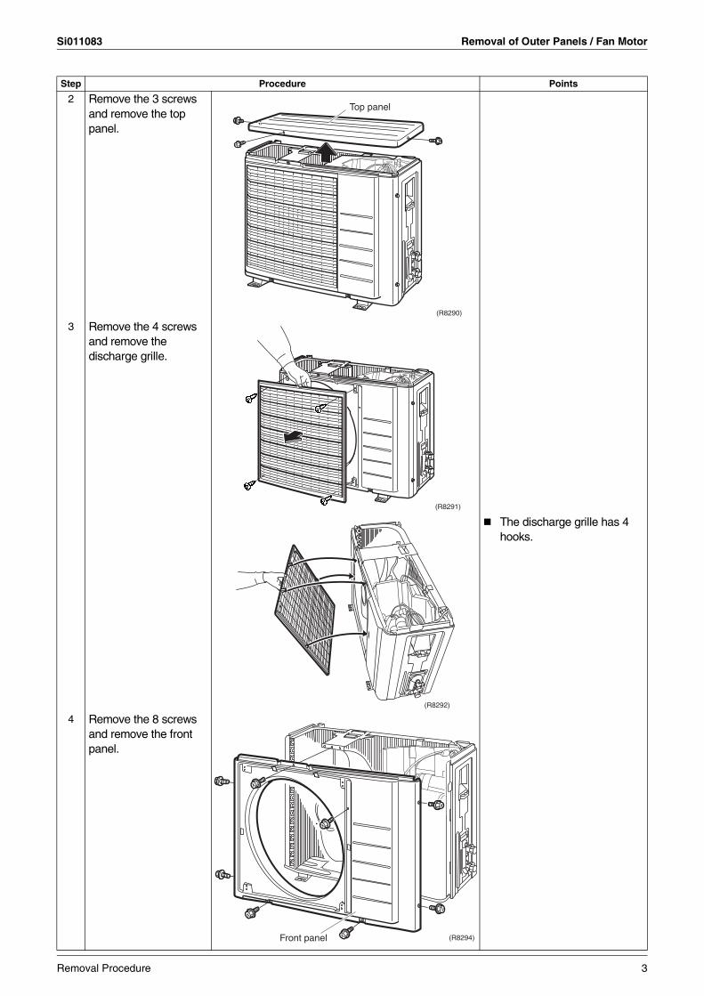
2 Remove the 3 screws and remove the top panel.
3 Remove the 4 screws and remove the discharge grille.
The discharge grille has 4 hooks.
4 Remove the 8 screws and remove the front panel.
Step Procedure Points
DAIKININVERTER
Top panel
(R8290)
DAIKININVERTER
(R8291)
(R8292)
DAIKININVERTER
(R8294)Front panel
Removal Procedure 3
Removal of Outer Panels / Fan Motor Si011083
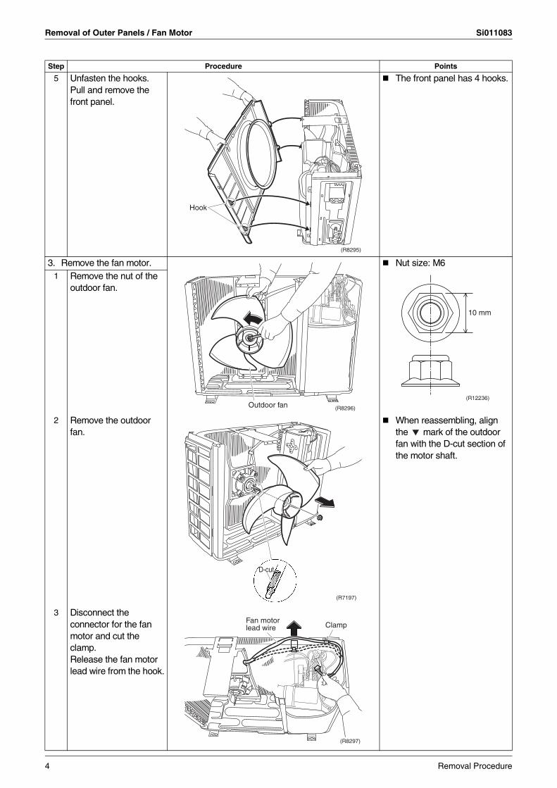
5 Unfasten the hooks.Pull and remove the front panel.
The front panel has 4 hooks.
3. Remove the fan motor. Nut size: M61 Remove the nut of the
outdoor fan.
2 Remove the outdoor fan.
When reassembling, align the mark of the outdoor fan with the D-cut section of the motor shaft.
3 Disconnect the connector for the fan motor and cut the clamp.Release the fan motor lead wire from the hook.
Step Procedure Points
(R8295)
Hook
(R8296)Outdoor fan
10 mm
(R12236)
D-cut
(R7197)
Fan motor lead wire Clamp
(R8297)
4 Removal Procedure
Si011083 Removal of Outer Panels / Fan Motor
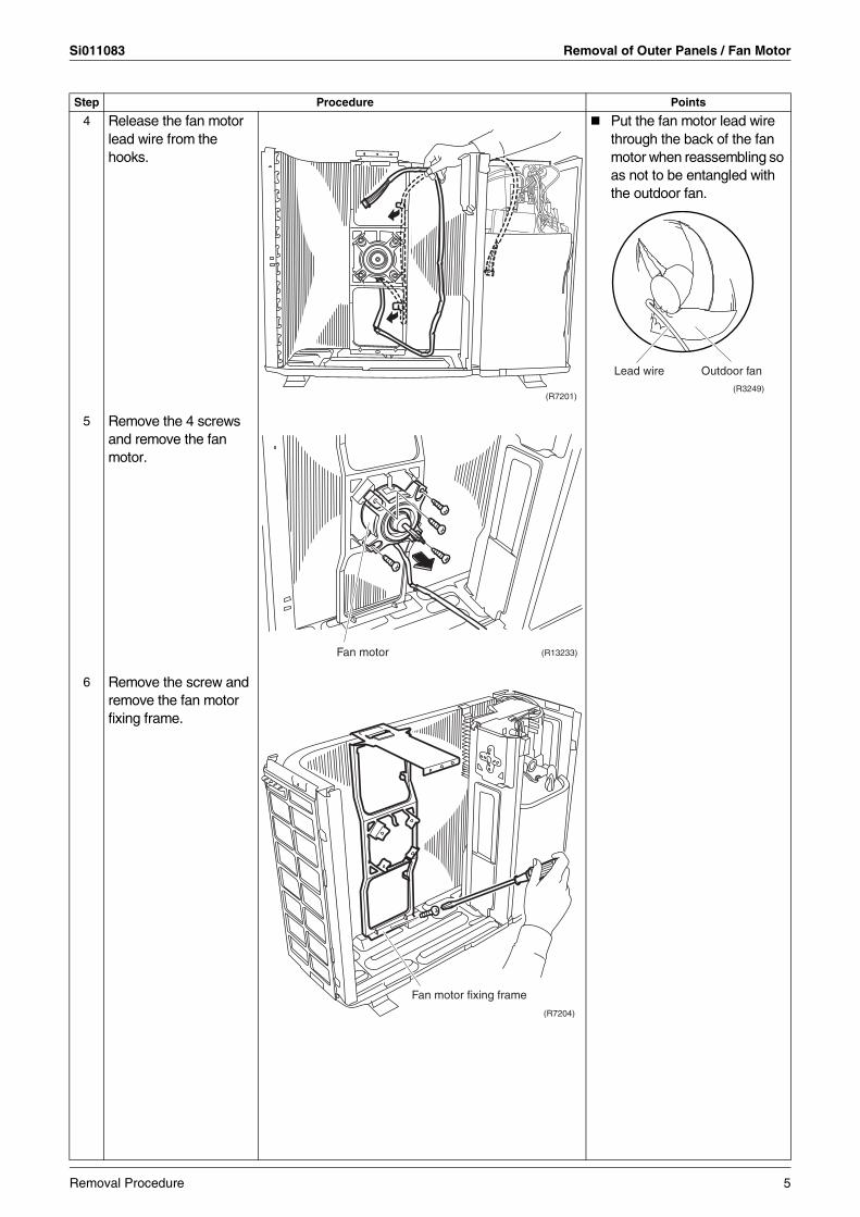
4 Release the fan motor lead wire from the hooks.
Put the fan motor lead wire through the back of the fan motor when reassembling so as not to be entangled with the outdoor fan.
5 Remove the 4 screws and remove the fan motor.
6 Remove the screw and remove the fan motor fixing frame.
Step Procedure Points
(R7201)(R3249)
Lead wire Outdoor fan
Fan motor (R13233)
(R7204)
Fan motor fixing frame
Removal Procedure 5
Removal of Outer Panels / Fan Motor Si011083
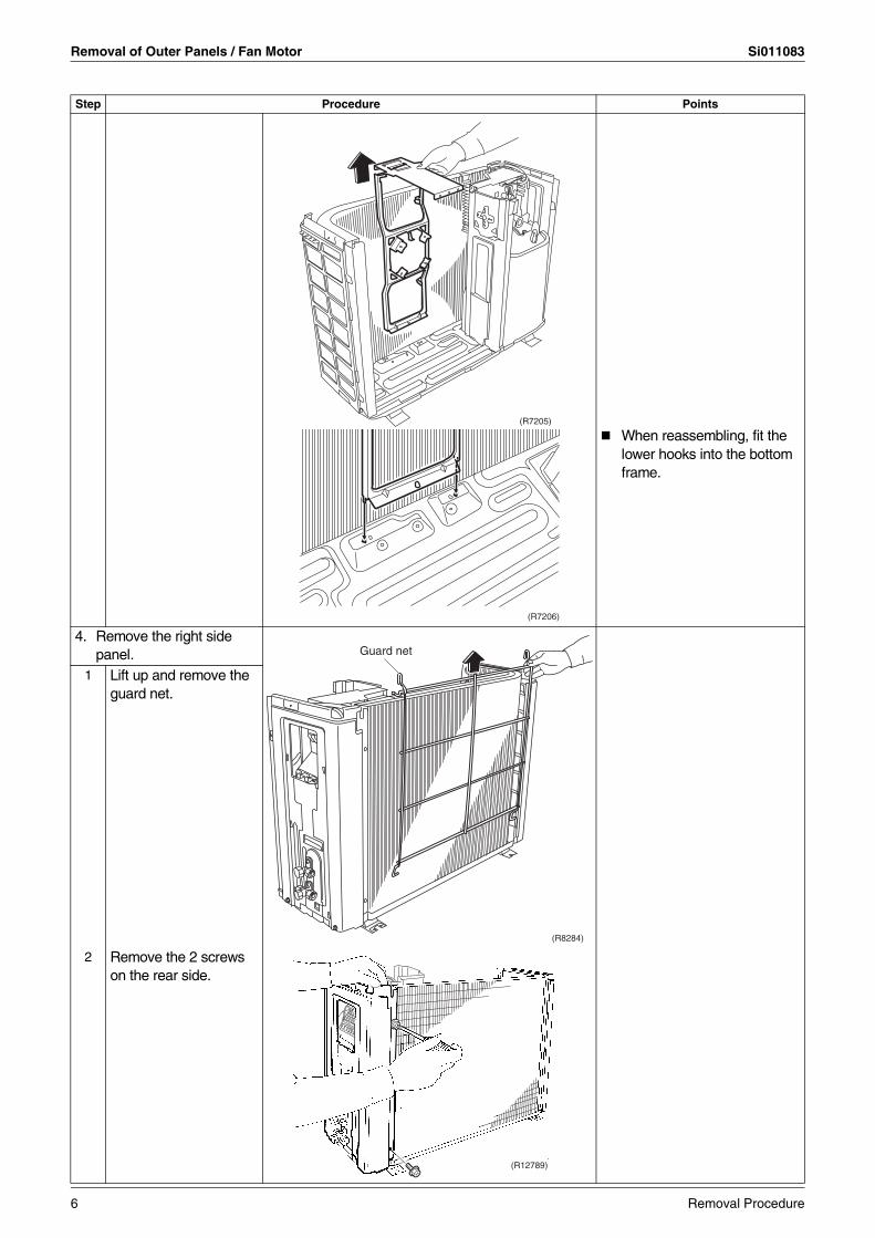
When reassembling, fit the lower hooks into the bottom frame.
4. Remove the right side panel.
1 Lift up and remove the guard net.
2 Remove the 2 screws on the rear side.
Step Procedure Points
(R7205)
(R7206)
Guard net
(R8284)
(R12789)
6 Removal Procedure
Si011083 Removal of Outer Panels / Fan Motor
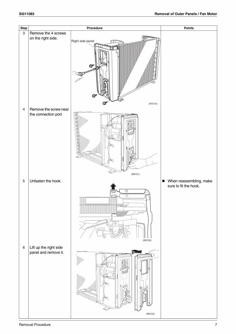
3 Remove the 4 screws on the right side.
4 Remove the screw near the connection port.
5 Unfasten the hook. When reassembling, make sure to fit the hook.
6 Lift up the right side panel and remove it.
Step Procedure Points
(R7210)
Right side panel
(R6721)
(R6722)
(R6723)
Removal Procedure 7
Removal of Electrical Components ASSY Si011083
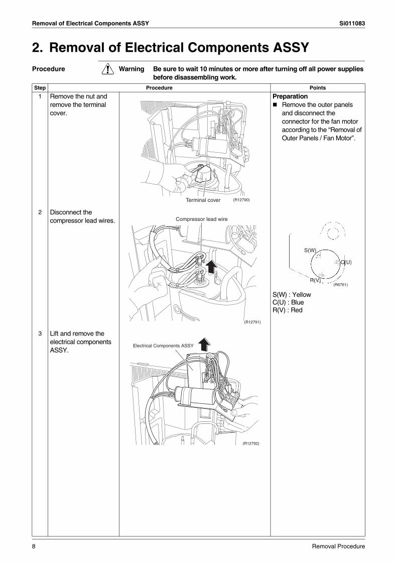
2. Removal of Electrical Components ASSYProcedure Warning Be sure to wait 10 minutes or more after turning off all power supplies
before disassembling work.
Step Procedure Points
1 Remove the nut and remove the terminal cover.
PreparationRemove the outer panels and disconnect the connector for the fan motor according to the “Removal of Outer Panels / Fan Motor”.
2 Disconnect the compressor lead wires.
S(W) : YellowC(U) : BlueR(V) : Red
3 Lift and remove the electrical components ASSY.
(R12790)Terminal cover
(R12791)
Compressor lead wire
S(W)
C(U)
R(V)(R6761)
(R12792)
Electrical Components ASSY
8 Removal Procedure
Si011083 Removal of Sound Blanket
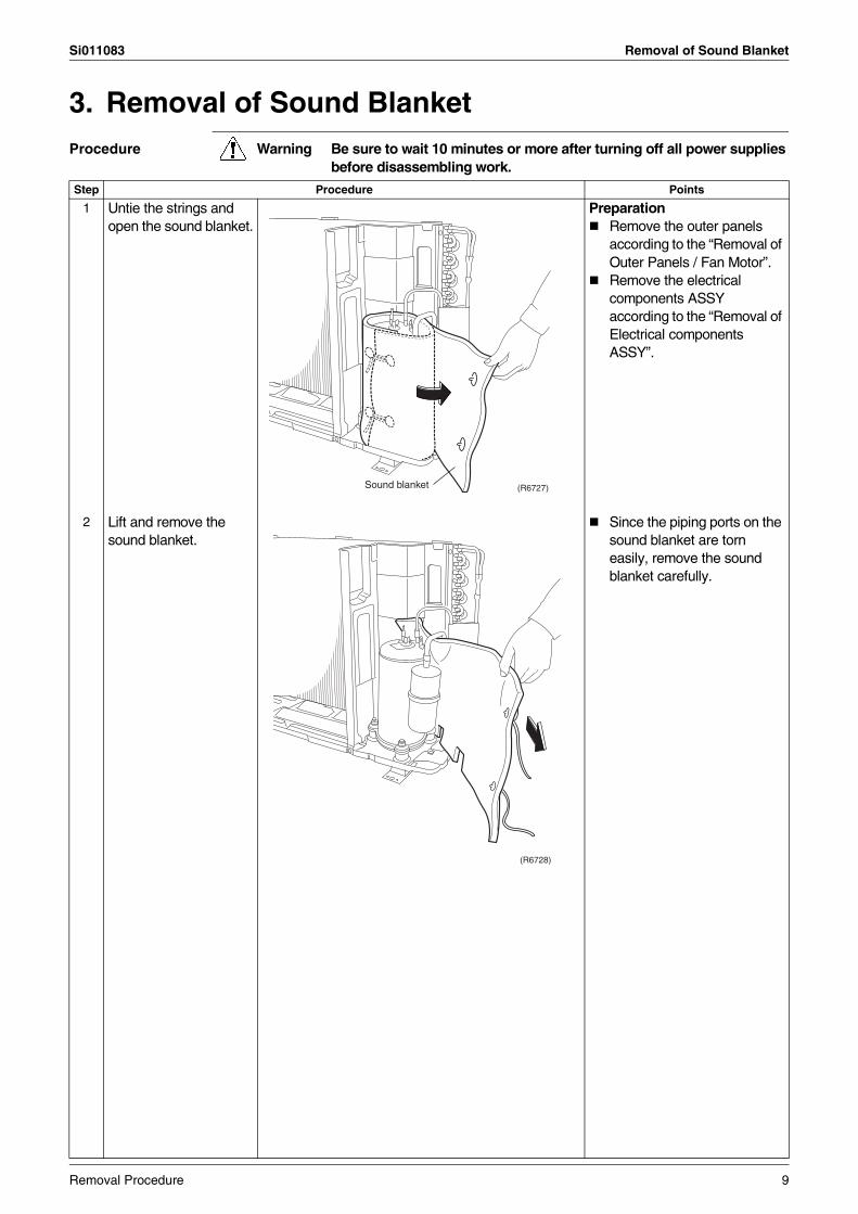
3. Removal of Sound BlanketProcedure Warning Be sure to wait 10 minutes or more after turning off all power supplies
before disassembling work.
Step Procedure Points
1 Untie the strings and open the sound blanket.
PreparationRemove the outer panels according to the “Removal of Outer Panels / Fan Motor”.Remove the electrical components ASSY according to the “Removal of Electrical components ASSY”.
2 Lift and remove the sound blanket.
Since the piping ports on the sound blanket are torn easily, remove the sound blanket carefully.
Sound blanket (R6727)
(R6728)
Removal Procedure 9
Removal of Compressor Si011083
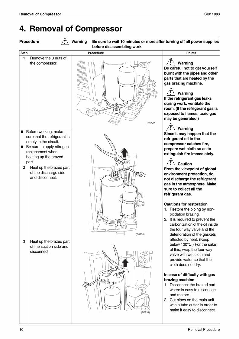
4. Removal of CompressorProcedure Warning Be sure to wait 10 minutes or more after turning off all power supplies
before disassembling work.
Step Procedure Points
1 Remove the 3 nuts of the compressor. Warning
Be careful not to get yourself burnt with the pipes and other parts that are heated by the gas brazing machine.
WarningIf the refrigerant gas leaks during work, ventilate the room. (If the refrigerant gas is exposed to flames, toxic gas may be generated.)
WarningSince it may happen that the refrigerant oil in the compressor catches fire, prepare wet cloth so as to extinguish fire immediately.
CautionFrom the viewpoint of global environment protection, do not discharge the refrigerant gas in the atmosphere. Make sure to collect all the refrigerant gas.
Cautions for restoration1. Restore the piping by non-
oxidation brazing. 2. It is required to prevent the
carbonization of the oil inside the four way valve and the deterioration of the gaskets affected by heat. (Keep below 120°C.) For the sake of this, wrap the four way valve with wet cloth and provide water so that the cloth does not dry.
In case of difficulty with gas brazing machine 1. Disconnect the brazed part
where is easy to disconnect and restore.
2. Cut pipes on the main unit with a tube cutter in order to make it easy to disconnect.
Before working, make sure that the refrigerant is empty in the circuit.Be sure to apply nitrogen replacement when heating up the brazed part.
2 Heat up the brazed part of the discharge side and disconnect.
3 Heat up the brazed part of the suction side and disconnect.
(R6729)
(R6730)
(R6731)
10 Removal Procedure
Si011083 Removal of Compressor
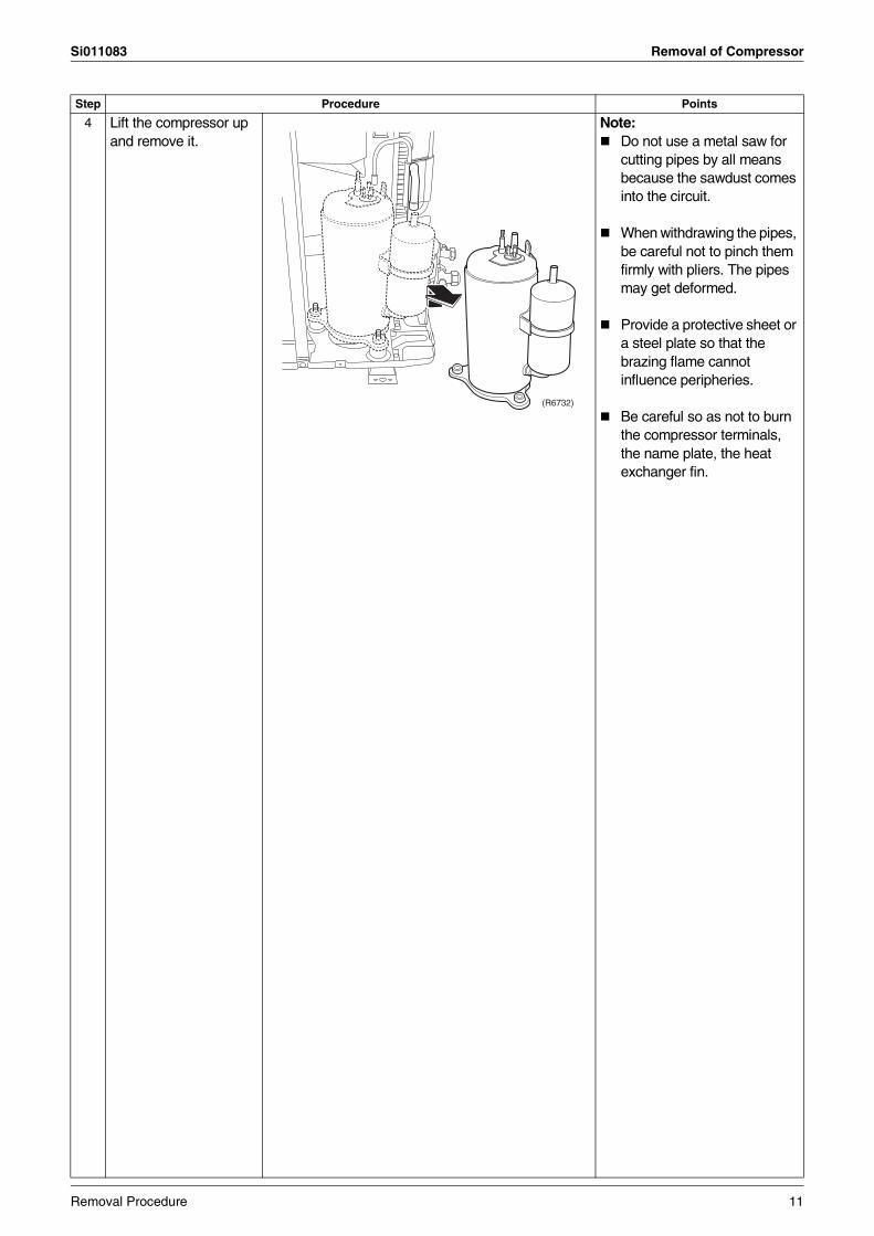
4 Lift the compressor up and remove it.
Note:Do not use a metal saw for cutting pipes by all means because the sawdust comes into the circuit.
When withdrawing the pipes, be careful not to pinch them firmly with pliers. The pipes may get deformed.
Provide a protective sheet or a steel plate so that the brazing flame cannot influence peripheries.
Be careful so as not to burn the compressor terminals, the name plate, the heat exchanger fin.
Step Procedure Points
(R6732)
Removal Procedure 11

Revision History
Month / Year Version Revised contents
01 / 2013 Si011083 First edition
Head Office:Umeda Center Bldg., 2-4-12, Nakazaki-Nishi,Kita-ku, Osaka, 530-8323 Japan
Tokyo Office:JR Shinagawa East Bldg., 2-18-1, Konan,Minato-ku, Tokyo, 108-0075 Japan
http://www.daikin.com/global_ac/
All rights reservedc
Warning Daikin products are manufactured for export to numerous countries throughout the world. Prior to purchase, please confirm with your local authorised importer, distributor and/or retailer whether this product conforms to the applicable standards, and is suitable for use, in the region where the product will be used. This statement does not purport to exclude, restrict or modify the application of any local legislation.
Ask a qualified installer or contractor to install this product. Do not try to install the product yourself. Improper installation can result in water or refrigerant leakage, electrical shock, fire or explosion.
Use only those parts and accessories supplied or specified by Daikin. Ask a qualified installer or contractor to install those parts and accessories. Use of unauthorised parts and accessories or improper installation of parts and accessories can result in water or refrigerant leakage, electrical shock, fire or explosion.
Read the User's Manual carefully before using this product. The User's Manual provides important safety instructions and warnings. Be sure to follow these instructions and warnings.
If you have any enquiries, please contact your local importer, distributor and/or retailer.
Cautions on product corrosion1. Air conditioners should not be installed in areas where corrosive gases, such as acid gas or alkaline gas, are produced.2. If the outdoor unit is to be installed close to the sea shore, direct exposure to the sea breeze should be avoided. If you need to install
the outdoor unit close to the sea shore, contact your local distributor.
Dealer
Specifications, designs and other content appearing in this brochure are current as of January 2013 but subject to change without notice.Si011083
01/2013 AK.B