Embed Size (px)
Citation preview
REPORT NUMBER-3169820COQ-001 ORIGINAL ISSUE DATE: Jan 28, 2009
REVISED DATE: August 12, 2009
EVALUATION CENTER
Intertek Testing Services NA Ltd. 1500 Brigantine Drive
Coquitlam, B.C. V3K 7C1
RENDERED TO
ITW Building Components Group Inc. 13389 Lakefront Drive Earth City, MO 63045
USA
PRODUCT EVALUATED: Truss Plates EVALUATION PROPERTY: Fire Resistance
Engineering Evaluation of Truss Plates for compliance with the applicable requirements of the following criteria: ASTM E119-08a, and CAN/ULC S101-07, “Standard Method of Tests of Building Construction and Materials”.
ENG
INEE
RIN
G E
VALU
ATI
ON
This report is for the exclusive use of Intertek's Client and is provided pursuant to the agreement between Intertek and its Client. Intertek's responsibility and liability are limited to the terms and conditions of the agreement. Intertek assumes no liability to any party, other than to the Client in accordance with the agreement, for any loss, expense or damage occasioned by the use of this report. Only the Client is authorized to copy or distribute this report and then only in its entirety. Any use of the Intertek name or one of its marks for the sale or advertisement of the tested material, product or service must first be approved in writing by Intertek. The observations and test results in this report are relevant only to the sample tested. This report by itself does not imply that the material, product, or service is or has ever been under an Intertek certification program.
1
ITW Building Components Group Inc. January 28, 2009 Project No. 3169820COQ-001 Revised August 12, 2009
Page 2 of 25
1 Introduction Intertek has conducted an engineering evaluation for ITW Building Components Group Inc. (ITWBCG), also known as Alpine Systems Corporation as referenced in Intertek file no. 3169820, to evaluate the use of SpaceJoist™ and ITWBCG metal truss plates for use in constructing trusses for use in fire rated floor/ceiling assemblies. The evaluation was conducted to determine if the ITW floor/ceiling assemblies will provide fire resistance ratings in accordance with ASTM E-119-08a and CAN/ULC S101-07 “Standard Method of Fire Tests of Building Construction and Materials”.
2 Sample and Assembly Description ITW Building Components Group Inc., also known as Alpine Systems Corporation, produces steel truss plates and SpaceJoist™ metal webs that are used by individual wood truss manufacturers to construct wood truss structural members. The manufacturers use solid sawn wood members and fasten them together using the connectors, in accordance with ITW instructions to create a truss of defined structural and fire resistance properties. The SpaceJoist™ product is a steel connector and web component that attaches to top and bottom wood chords to create a truss. The ITWBCG truss plates are steel connector plates that are used on each side of the wood truss members to connect them together.
3 Reference Documents Factory Mutual Test Report No. J.I. 1A0Q2.AC Class 4610 dated May 13, 1977, Report Serial No. 24768 (Class 4610) dated July 25, 1974, Report No. J.I. OE6Q7.AC (Class 4610) dated January 31, 1980, Report No. J.I. OA8Q8.AC dated May 10, 1977, and J.I. OA5Q33.AC dated April 13, 1977. National research Council of Canada Test Reports; 873-NV, 874 NV, 975-NV, 976-NV, 977-NV, 978-NV, 985-NV, 986-NV, 987-NV, 988-NV,992-NV, 993-NV, 994-NV, 995-NV, describing sound transmission performance of floor/ceiling assemblies, and Test Report No. F-10-160 dated January 30, 1984 describing Fire Resistance. Underwriters Laboratories Inc. File R9500-1 dated 2-21-81. Warnock Hersey International Inc., Report No. WHI-694-011 dated July 14, 1981. Intertek File Number 491-6738 dated 1994.
ITW Building Components Group Inc. January 28, 2009 Project No. 3169820COQ-001 Revised August 12, 2009
Page 3 of 25
4 Evaluation Method Intertek had previously reviewed the referenced test reports to develop a series of Listings for Truswal Systems, Inc. With the acquisition of Truswal Systems by ITW Building Components, the Listings need to be revised to reflect the ITW company names and product designations. The revised Listings are shown in the Appendix of this report. The Listing text was also reviewed for accuracy, and to be updated as follows;
• Replace reference to Truswal to ITW Building Components Group Inc., also known as Alpine Systems Corporation.
• Replace reference to FlorTrusTM to Floor Truss
• Replace reference to FlorTrusTM steel truss plates to ITWBCG steel truss plates
• Update gypsum wallboard references, as Westroc is now BPB, and the USG/CGC
manufacturer designation was missing.
• Update and make editorial changes to General Information section.
• Addition of ™ designation where required.
• Revise Flooring description to read as follows; Flooring: Minimum 5/8" (15.9mm) plywood or panel product (See General Information ).
• Add the option of the use of gypsum based proprietary topping, as these materials add to the fire resistance of the assembly. Light weight topping was already included.
• Add the requirement that gypsum boards to be installed perpendicular to joists or channels.
• Repaced the word “screwed” with “fastened”.
• Change the phrase “gyproc joint filler” to “gypsum joint compound”.
• Edit for wording consistency as required in the individual Listings.
• Remove reference to SpaceJoist TETM product.
ITW Building Components Group Inc. January 28, 2009 Project No. 3169820COQ-001 Revised August 12, 2009
Page 4 of 25
5 Conclusion The ITW Building Components Group Inc. SpaceJoist™ and ITWBCG metal truss plates are eligible for use in wood truss fire rated assembly designs.. The floor/ceiling and roof/ceiling assembly ratings shown in the enclosed revised Listings are provided in accordance with ASTM E-119-08a and CAN/ULC S101-07 “Standard Method for Fire Tests of Building Construction and Materials”.
6 Signatures INTERTEK TESTING SERVICES NA Ltd. Reported by: Mike van Geyn, AScT Project Manager, Engineering Services Reviewed by: _____________________ Michael E. Luna General Manager, Building Products ATTACHMENTS:
ITW Building Components Group Inc. January 28, 2009 Project No. 3169820COQ-001 Revised August 12, 2009
Page 5 of 25
ATTACHMENTS
Revised Listings
ITW Building Components Group Inc. January 28, 2009 Project No. 3169820COQ-001 Revised August 12, 2009
Page 6 of 25
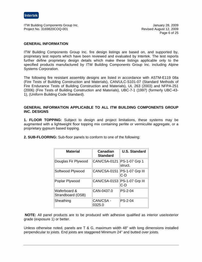
GENERAL INFORMATION ITW Building Components Group Inc. fire design listings are based on, and supported by, proprietary test reports which have been reviewed and evaluated by Intertek. The test reports further define proprietary design details which make these listings applicable only to the specified products manufactured by ITW Building Components Group Inc. including Alpine Systems Corporation.
The following fire resistant assembly designs are listed in accordance with ASTM-E119 08a (Fire Tests of Building Construction and Materials), CAN/ULC-S101-07 (Standard Methods of Fire Endurance Tests of Building Construction and Materials), UL 263 (2003) and NFPA-251 (2006) (Fire Tests of Building Construction and Materials), UBC-7-1 (1997) (formerly UBC-43-1), (Uniform Building Code Standard).
GENERAL INFORMATION APPLICABLE TO ALL ITW BUILDING COMPONENTS GROUP INC. DESIGNS 1. FLOOR TOPPING: Subject to design and project limitations, these systems may be augmented with a lightweight floor topping mix containing perlite or vermiculite aggregate, or a proprietary gypsum based topping.
2. SUB-FLOORING: Sub-floor panels to conform to one of the following:
Material Canadian
Standard U.S. Standard
Douglas Fir Plywood CAN/CSA-0121 PS-1-07 Grp 1 struct.
Softwood Plywood CAN/CSA-0151 PS-1-07 Grp III C-D
Poplar Plywood CAN/CSA-0153 PS-1-07 Grp III C-D
Waferboard & Strandboard (OSB)
CAN-0437.0 PS-2-04
Sheathing CAN/CSA -0325.0
PS-2-04
NOTE: All panel products are to be produced with adhesive qualified as interior use/exterior grade (exposure 1) or better.
Unless otherwise noted, panels are T & G, maximum width 48" with long dimensions installed perpendicular to joists. End joists are staggered Minimum 24" and butted over joists.
ITW Building Components Group Inc. January 28, 2009 Project No. 3169820COQ-001 Revised August 12, 2009
Page 7 of 25
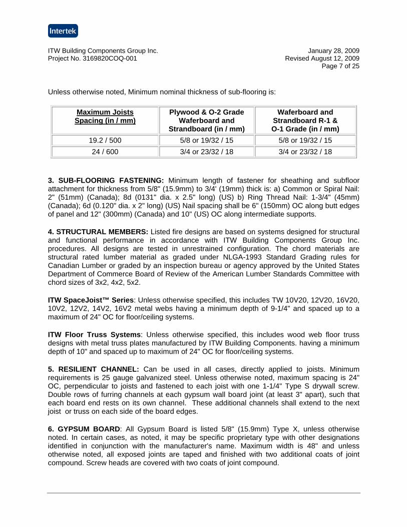
Unless otherwise noted, Minimum nominal thickness of sub-flooring is:
Maximum Joists Spacing (in / mm)
Plywood & O-2 Grade Waferboard and
Strandboard (in / mm)
Waferboard and Strandboard R-1 & O-1 Grade (in / mm)
19.2 / 500 5/8 or 19/32 / 15 5/8 or 19/32 / 15 24 / 600 3/4 or 23/32 / 18 3/4 or 23/32 / 18
3. SUB-FLOORING FASTENING: Minimum length of fastener for sheathing and subfloor attachment for thickness from 5/8" (15.9mm) to 3/4' (19mm) thick is: a) Common or Spiral Nail: 2" (51mm) (Canada); 8d (0131" dia. x 2.5" long) (US) b) Ring Thread Nail: 1-3/4" (45mm) (Canada); 6d (0.120" dia. x 2" long) (US) Nail spacing shall be 6" (150mm) OC along butt edges of panel and 12" (300mm) (Canada) and 10" (US) OC along intermediate supports.
4. STRUCTURAL MEMBERS: Listed fire designs are based on systems designed for structural and functional performance in accordance with ITW Building Components Group Inc. procedures. All designs are tested in unrestrained configuration. The chord materials are structural rated lumber material as graded under NLGA-1993 Standard Grading rules for Canadian Lumber or graded by an inspection bureau or agency approved by the United States Department of Commerce Board of Review of the American Lumber Standards Committee with chord sizes of 3x2, 4x2, 5x2.
ITW SpaceJoist™ Series: Unless otherwise specified, this includes TW 10V20, 12V20, 16V20, 10V2, 12V2, 14V2, 16V2 metal webs having a minimum depth of 9-1/4" and spaced up to a maximum of 24" OC for floor/ceiling systems.
ITW Floor Truss Systems: Unless otherwise specified, this includes wood web floor truss designs with metal truss plates manufactured by ITW Building Components. having a minimum depth of 10" and spaced up to maximum of 24" OC for floor/ceiling systems.
5. RESILIENT CHANNEL: Can be used in all cases, directly applied to joists. Minimum requirements is 25 gauge galvanized steel. Unless otherwise noted, maximum spacing is 24" OC, perpendicular to joists and fastened to each joist with one 1-1/4" Type S drywall screw. Double rows of furring channels at each gypsum wall board joint (at least 3" apart), such that each board end rests on its own channel. These additional channels shall extend to the next joist or truss on each side of the board edges.
6. GYPSUM BOARD: All Gypsum Board is listed 5/8" (15.9mm) Type X, unless otherwise noted. In certain cases, as noted, it may be specific proprietary type with other designations identified in conjunction with the manufacturer's name. Maximum width is 48" and unless otherwise noted, all exposed joints are taped and finished with two additional coats of joint compound. Screw heads are covered with two coats of joint compound.
ITW Building Components Group Inc. January 28, 2009 Project No. 3169820COQ-001 Revised August 12, 2009
Page 8 of 25
7. BRIDGING/STRONGBACK: 2 x 6 Bridging/Strongback to be attached to each bottom chord of the assembly with two 3" screws and to be spaced at 7' OC maximum.
8. INSULATION: All batts are to be placed between bottom joist flanges and supported by metal furring channels. In assemblies where metal furring channels are not utilized, support insulation batts on nominal 1" x 3" wood furring strips spaced 16" OC along the top side of the bottom flange. Equivalent methods that retain insulation above joist bottom flange are acceptable. All butt joints shall be over furring channels.
9. SUSPENDED CEILING SYSTEM: Any suspended ceiling system may be selected which satisfies the following criteria:
a. It must be a Listed fire rated system, Listed for use in a similar assembly, and be installed within the terms of its listing b. It must have a finish rating equal to or greater than the finish rating required by the suspended ceiling design. c. It must be suspended in accordance with the terms of its listing and a minimum of 7-1/2" below the joist. d. Penetrations such as ducts, air diffusers, and fixtures must be protected in such a manner as to conform to the terms of the listing of the suspended ceiling system.
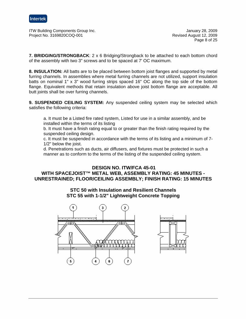
DESIGN NO. ITW/FCA 45-01
WITH SPACEJOIST™ METAL WEB, ASSEMBLY RATING: 45 MINUTES - UNRESTRAINED; FLOOR/CEILING ASSEMBLY; FINISH RATING: 15 MINUTES
STC 50 with Insulation and Resilient Channels STC 55 with 1-1/2" Lightweight Concrete Topping
ITW Building Components Group Inc. January 28, 2009 Project No. 3169820COQ-001 Revised August 12, 2009
Page 9 of 25
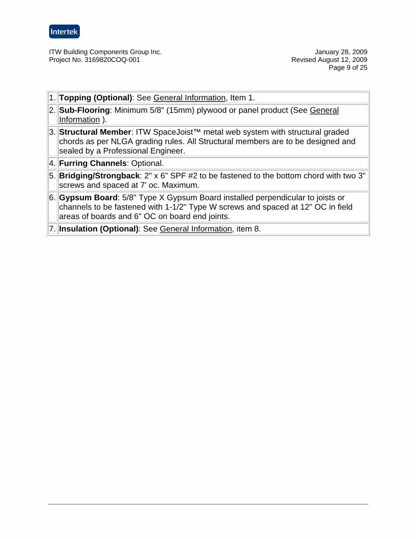
1. Topping (Optional): See General Information, Item 1. 2. Sub-Flooring: Minimum 5/8" (15mm) plywood or panel product (See General
Information ). 3. Structural Member: ITW SpaceJoist™ metal web system with structural graded
chords as per NLGA grading rules. All Structural members are to be designed and sealed by a Professional Engineer.
4. Furring Channels: Optional. 5. Bridging/Strongback: 2" x 6" SPF #2 to be fastened to the bottom chord with two 3"
screws and spaced at 7' oc. Maximum. 6. Gypsum Board: 5/8" Type X Gypsum Board installed perpendicular to joists or
channels to be fastened with 1-1/2" Type W screws and spaced at 12" OC in field areas of boards and 6" OC on board end joints.
7. Insulation (Optional): See General Information, item 8.
ITW Building Components Group Inc. January 28, 2009 Project No. 3169820COQ-001 Revised August 12, 2009
Page 10 of 25
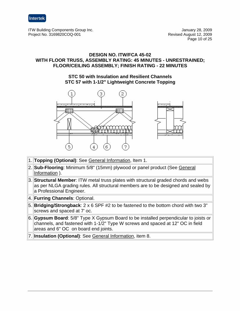
DESIGN NO. ITW/FCA 45-02 WITH FLOOR TRUSS, ASSEMBLY RATING: 45 MINUTES - UNRESTRAINED;
FLOOR/CEILING ASSEMBLY; FINISH RATING - 22 MINUTES
STC 50 with Insulation and Resilient Channels STC 57 with 1-1/2" Lightweight Concrete Topping
1. Topping (Optional): See General Information, Item 1. 2. Sub-Flooring: Minimum 5/8" (15mm) plywood or panel product (See General
Information ). 3. Structural Member: ITW metal truss plates with structural graded chords and webs
as per NLGA grading rules. All structural members are to be designed and sealed by a Professional Engineer.
4. Furring Channels: Optional. 5. Bridging/Strongback: 2 x 6 SPF #2 to be fastened to the bottom chord with two 3"
screws and spaced at 7' oc. 6. Gypsum Board: 5/8" Type X Gypsum Board to be installed perpendicular to joists or
channels, and fastened with 1-1/2" Type W screws and spaced at 12" OC in field areas and 6" OC on board end joints.
7. Insulation (Optional): See General Information, item 8.
ITW Building Components Group Inc. January 28, 2009 Project No. 3169820COQ-001 Revised August 12, 2009
Page 11 of 25
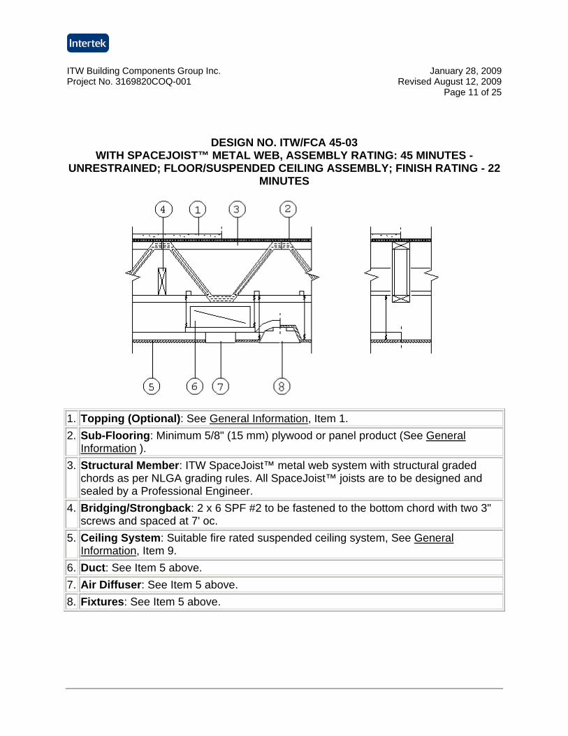
DESIGN NO. ITW/FCA 45-03 WITH SPACEJOIST™ METAL WEB, ASSEMBLY RATING: 45 MINUTES -
UNRESTRAINED; FLOOR/SUSPENDED CEILING ASSEMBLY; FINISH RATING - 22 MINUTES
1. Topping (Optional): See General Information, Item 1. 2. Sub-Flooring: Minimum 5/8" (15 mm) plywood or panel product (See General
Information ). 3. Structural Member: ITW SpaceJoist™ metal web system with structural graded
chords as per NLGA grading rules. All SpaceJoist™ joists are to be designed and sealed by a Professional Engineer.
4. Bridging/Strongback: 2 x 6 SPF #2 to be fastened to the bottom chord with two 3" screws and spaced at 7' oc.
5. Ceiling System: Suitable fire rated suspended ceiling system, See General Information, Item 9.
6. Duct: See Item 5 above. 7. Air Diffuser: See Item 5 above. 8. Fixtures: See Item 5 above.
ITW Building Components Group Inc. January 28, 2009 Project No. 3169820COQ-001 Revised August 12, 2009
Page 12 of 25
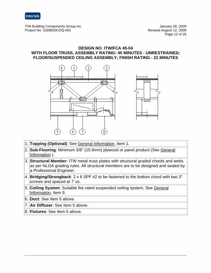
DESIGN NO. ITW/FCA 45-04 WITH FLOOR TRUSS, ASSEMBLY RATING: 45 MINUTES - UNRESTRAINED; FLOOR/SUSPENDED CEILING ASSEMBLY; FINISH RATING - 22 MINUTES
1. Topping (Optional): See General Information, Item 1. 2. Sub-Flooring: Minimum 5/8" (15.9mm) plywood or panel product (See General
Information ). 3. Structural Member: ITW metal truss plates with structural graded chords and webs
as per NLGA grading rules. All structural members are to be designed and sealed by a Professional Engineer.
4. Bridging/Strongback: 2 x 6 SPF #2 to be fastened to the bottom chord with two 3" screws and spaced at 7' oc.
5. Ceiling System: Suitable fire rated suspended ceiling system, See General Information, Item 9.
6. Duct: See Item 5 above. 7. Air Diffuser: See Item 5 above. 8. Fixtures: See Item 5 above.
ITW Building Components Group Inc. January 28, 2009 Project No. 3169820COQ-001 Revised August 12, 2009
Page 13 of 25
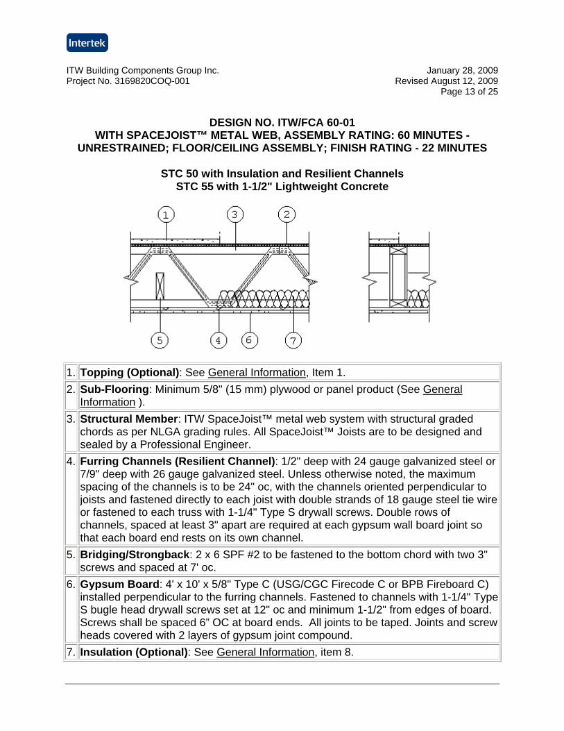
DESIGN NO. ITW/FCA 60-01
WITH SPACEJOIST™ METAL WEB, ASSEMBLY RATING: 60 MINUTES - UNRESTRAINED; FLOOR/CEILING ASSEMBLY; FINISH RATING - 22 MINUTES
STC 50 with Insulation and Resilient Channels STC 55 with 1-1/2" Lightweight Concrete
1. Topping (Optional): See General Information, Item 1. 2. Sub-Flooring: Minimum 5/8" (15 mm) plywood or panel product (See General
Information ). 3. Structural Member: ITW SpaceJoist™ metal web system with structural graded
chords as per NLGA grading rules. All SpaceJoist™ Joists are to be designed and sealed by a Professional Engineer.
4. Furring Channels (Resilient Channel): 1/2" deep with 24 gauge galvanized steel or 7/9" deep with 26 gauge galvanized steel. Unless otherwise noted, the maximum spacing of the channels is to be 24" oc, with the channels oriented perpendicular to joists and fastened directly to each joist with double strands of 18 gauge steel tie wire or fastened to each truss with 1-1/4" Type S drywall screws. Double rows of channels, spaced at least 3" apart are required at each gypsum wall board joint so that each board end rests on its own channel.
5. Bridging/Strongback: 2 x 6 SPF #2 to be fastened to the bottom chord with two 3" screws and spaced at 7' oc.
6. Gypsum Board: 4' x 10' x 5/8" Type C (USG/CGC Firecode C or BPB Fireboard C) installed perpendicular to the furring channels. Fastened to channels with 1-1/4" Type S bugle head drywall screws set at 12" oc and minimum 1-1/2" from edges of board. Screws shall be spaced 6” OC at board ends. All joints to be taped. Joints and screw heads covered with 2 layers of gypsum joint compound.
7. Insulation (Optional): See General Information, item 8.
ITW Building Components Group Inc. January 28, 2009 Project No. 3169820COQ-001 Revised August 12, 2009
Page 14 of 25
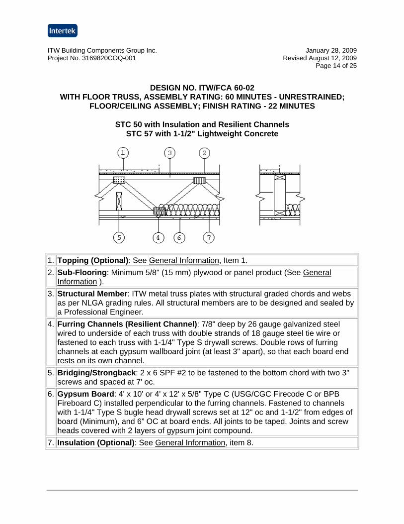
DESIGN NO. ITW/FCA 60-02
WITH FLOOR TRUSS, ASSEMBLY RATING: 60 MINUTES - UNRESTRAINED; FLOOR/CEILING ASSEMBLY; FINISH RATING - 22 MINUTES
STC 50 with Insulation and Resilient Channels STC 57 with 1-1/2" Lightweight Concrete
1. Topping (Optional): See General Information, Item 1. 2. Sub-Flooring: Minimum 5/8" (15 mm) plywood or panel product (See General
Information ). 3. Structural Member: ITW metal truss plates with structural graded chords and webs
as per NLGA grading rules. All structural members are to be designed and sealed by a Professional Engineer.
4. Furring Channels (Resilient Channel): 7/8" deep by 26 gauge galvanized steel wired to underside of each truss with double strands of 18 gauge steel tie wire or fastened to each truss with 1-1/4" Type S drywall screws. Double rows of furring channels at each gypsum wallboard joint (at least 3" apart), so that each board end rests on its own channel.
5. Bridging/Strongback: 2 x 6 SPF #2 to be fastened to the bottom chord with two 3" screws and spaced at 7' oc.
6. Gypsum Board: 4' x 10' or 4' x 12' x 5/8" Type C (USG/CGC Firecode C or BPB Fireboard C) installed perpendicular to the furring channels. Fastened to channels with 1-1/4" Type S bugle head drywall screws set at 12" oc and 1-1/2" from edges of board (Minimum), and 6” OC at board ends. All joints to be taped. Joints and screw heads covered with 2 layers of gypsum joint compound.
7. Insulation (Optional): See General Information, item 8.
ITW Building Components Group Inc. January 28, 2009 Project No. 3169820COQ-001 Revised August 12, 2009
Page 15 of 25
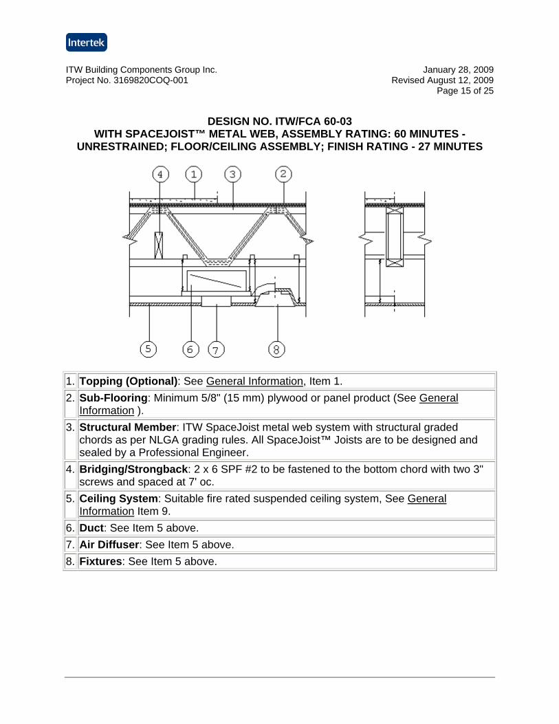
DESIGN NO. ITW/FCA 60-03
WITH SPACEJOIST™ METAL WEB, ASSEMBLY RATING: 60 MINUTES - UNRESTRAINED; FLOOR/CEILING ASSEMBLY; FINISH RATING - 27 MINUTES
1. Topping (Optional): See General Information, Item 1. 2. Sub-Flooring: Minimum 5/8" (15 mm) plywood or panel product (See General
Information ). 3. Structural Member: ITW SpaceJoist metal web system with structural graded
chords as per NLGA grading rules. All SpaceJoist™ Joists are to be designed and sealed by a Professional Engineer.
4. Bridging/Strongback: 2 x 6 SPF #2 to be fastened to the bottom chord with two 3" screws and spaced at 7' oc.
5. Ceiling System: Suitable fire rated suspended ceiling system, See General Information Item 9.
6. Duct: See Item 5 above. 7. Air Diffuser: See Item 5 above. 8. Fixtures: See Item 5 above.
ITW Building Components Group Inc. January 28, 2009 Project No. 3169820COQ-001 Revised August 12, 2009
Page 16 of 25
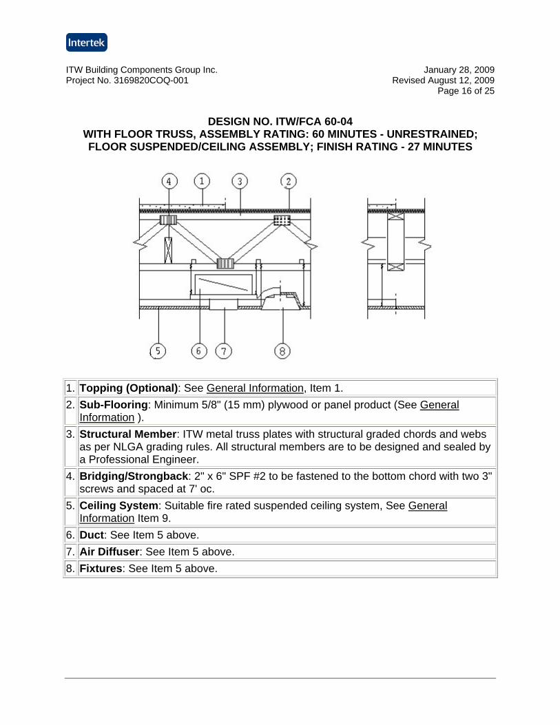
DESIGN NO. ITW/FCA 60-04
WITH FLOOR TRUSS, ASSEMBLY RATING: 60 MINUTES - UNRESTRAINED; FLOOR SUSPENDED/CEILING ASSEMBLY; FINISH RATING - 27 MINUTES
1. Topping (Optional): See General Information, Item 1. 2. Sub-Flooring: Minimum 5/8" (15 mm) plywood or panel product (See General
Information ). 3. Structural Member: ITW metal truss plates with structural graded chords and webs
as per NLGA grading rules. All structural members are to be designed and sealed by a Professional Engineer.
4. Bridging/Strongback: 2" x 6" SPF #2 to be fastened to the bottom chord with two 3" screws and spaced at 7' oc.
5. Ceiling System: Suitable fire rated suspended ceiling system, See General Information Item 9.
6. Duct: See Item 5 above. 7. Air Diffuser: See Item 5 above. 8. Fixtures: See Item 5 above.
ITW Building Components Group Inc. January 28, 2009 Project No. 3169820COQ-001 Revised August 12, 2009
Page 17 of 25
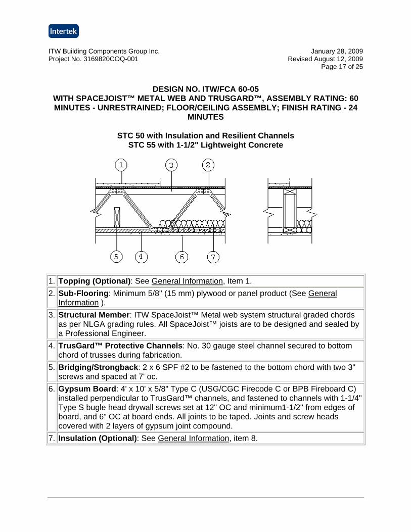
DESIGN NO. ITW/FCA 60-05
WITH SPACEJOIST™ METAL WEB AND TRUSGARD™, ASSEMBLY RATING: 60 MINUTES - UNRESTRAINED; FLOOR/CEILING ASSEMBLY; FINISH RATING - 24
MINUTES
STC 50 with Insulation and Resilient Channels STC 55 with 1-1/2" Lightweight Concrete
1. Topping (Optional): See General Information, Item 1. 2. Sub-Flooring: Minimum 5/8" (15 mm) plywood or panel product (See General
Information ). 3. Structural Member: ITW SpaceJoist™ Metal web system structural graded chords
as per NLGA grading rules. All SpaceJoist™ joists are to be designed and sealed by a Professional Engineer.
4. TrusGard™ Protective Channels: No. 30 gauge steel channel secured to bottom chord of trusses during fabrication.
5. Bridging/Strongback: 2 x 6 SPF #2 to be fastened to the bottom chord with two 3" screws and spaced at 7' oc.
6. Gypsum Board: 4' x 10' x 5/8" Type C (USG/CGC Firecode C or BPB Fireboard C) installed perpendicular to TrusGard™ channels, and fastened to channels with 1-1/4" Type S bugle head drywall screws set at 12" OC and minimum1-1/2" from edges of board, and 6” OC at board ends. All joints to be taped. Joints and screw heads covered with 2 layers of gypsum joint compound.
7. Insulation (Optional): See General Information, item 8.
ITW Building Components Group Inc. January 28, 2009 Project No. 3169820COQ-001 Revised August 12, 2009
Page 18 of 25
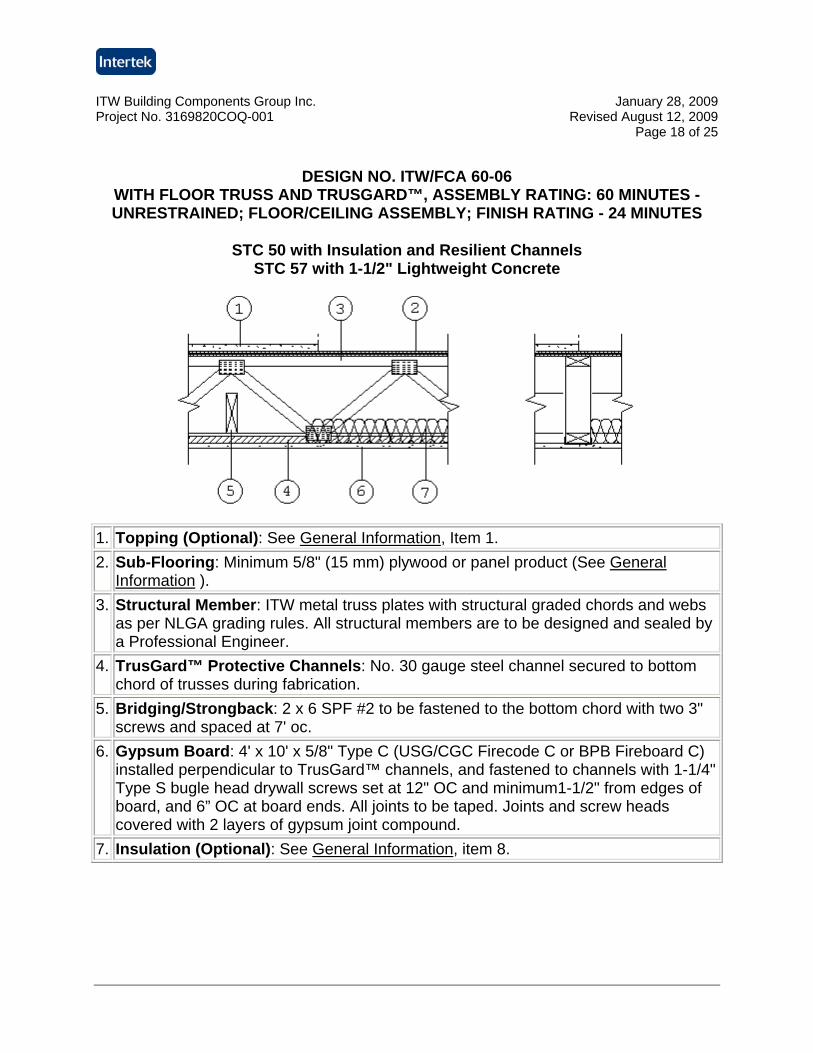
DESIGN NO. ITW/FCA 60-06
WITH FLOOR TRUSS AND TRUSGARD™, ASSEMBLY RATING: 60 MINUTES - UNRESTRAINED; FLOOR/CEILING ASSEMBLY; FINISH RATING - 24 MINUTES
STC 50 with Insulation and Resilient Channels STC 57 with 1-1/2" Lightweight Concrete
1. Topping (Optional): See General Information, Item 1. 2. Sub-Flooring: Minimum 5/8" (15 mm) plywood or panel product (See General
Information ). 3. Structural Member: ITW metal truss plates with structural graded chords and webs
as per NLGA grading rules. All structural members are to be designed and sealed by a Professional Engineer.
4. TrusGard™ Protective Channels: No. 30 gauge steel channel secured to bottom chord of trusses during fabrication.
5. Bridging/Strongback: 2 x 6 SPF #2 to be fastened to the bottom chord with two 3" screws and spaced at 7' oc.
6. Gypsum Board: 4' x 10' x 5/8" Type C (USG/CGC Firecode C or BPB Fireboard C) installed perpendicular to TrusGard™ channels, and fastened to channels with 1-1/4" Type S bugle head drywall screws set at 12" OC and minimum1-1/2" from edges of board, and 6” OC at board ends. All joints to be taped. Joints and screw heads covered with 2 layers of gypsum joint compound.
7. Insulation (Optional): See General Information, item 8.
ITW Building Components Group Inc. January 28, 2009 Project No. 3169820COQ-001 Revised August 12, 2009
Page 19 of 25
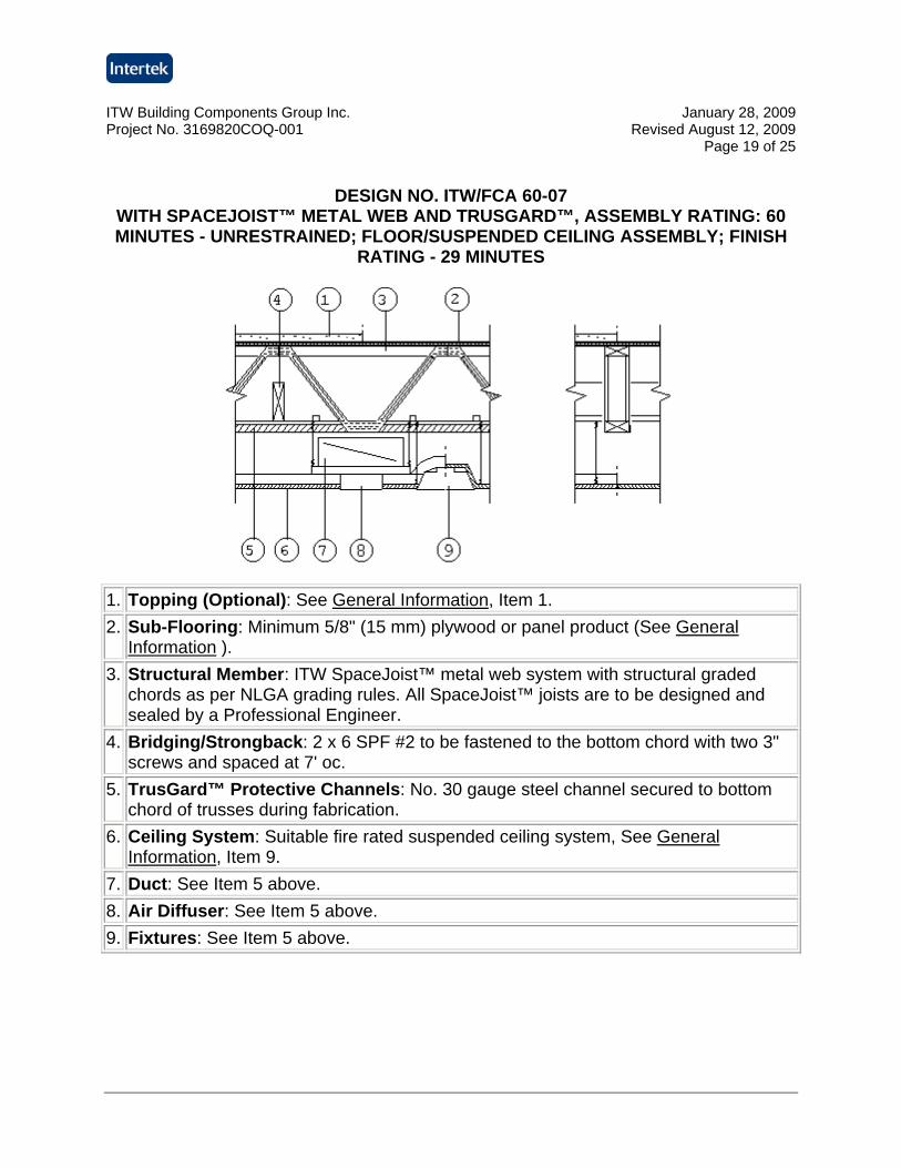
DESIGN NO. ITW/FCA 60-07
WITH SPACEJOIST™ METAL WEB AND TRUSGARD™, ASSEMBLY RATING: 60 MINUTES - UNRESTRAINED; FLOOR/SUSPENDED CEILING ASSEMBLY; FINISH
RATING - 29 MINUTES
1. Topping (Optional): See General Information, Item 1. 2. Sub-Flooring: Minimum 5/8" (15 mm) plywood or panel product (See General
Information ). 3. Structural Member: ITW SpaceJoist™ metal web system with structural graded
chords as per NLGA grading rules. All SpaceJoist™ joists are to be designed and sealed by a Professional Engineer.
4. Bridging/Strongback: 2 x 6 SPF #2 to be fastened to the bottom chord with two 3" screws and spaced at 7' oc.
5. TrusGard™ Protective Channels: No. 30 gauge steel channel secured to bottom chord of trusses during fabrication.
6. Ceiling System: Suitable fire rated suspended ceiling system, See General Information, Item 9.
7. Duct: See Item 5 above. 8. Air Diffuser: See Item 5 above. 9. Fixtures: See Item 5 above.
ITW Building Components Group Inc. January 28, 2009 Project No. 3169820COQ-001 Revised August 12, 2009
Page 20 of 25
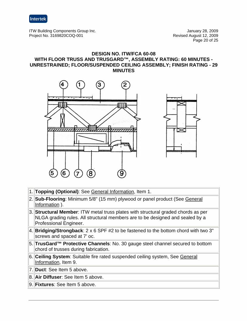
DESIGN NO. ITW/FCA 60-08
WITH FLOOR TRUSS AND TRUSGARD™, ASSEMBLY RATING: 60 MINUTES - UNRESTRAINED; FLOOR/SUSPENDED CEILING ASSEMBLY; FINISH RATING - 29
MINUTES
1. Topping (Optional): See General Information, Item 1. 2. Sub-Flooring: Minimum 5/8" (15 mm) plywood or panel product (See General
Information ). 3. Structural Member: ITW metal truss plates with structural graded chords as per
NLGA grading rules. All structural members are to be designed and sealed by a Professional Engineer.
4. Bridging/Strongback: 2 x 6 SPF #2 to be fastened to the bottom chord with two 3" screws and spaced at 7' oc.
5. TrusGard™ Protective Channels: No. 30 gauge steel channel secured to bottom chord of trusses during fabrication.
6. Ceiling System: Suitable fire rated suspended ceiling system, See General Information, Item 9.
7. Duct: See Item 5 above. 8. Air Diffuser: See Item 5 above. 9. Fixtures: See Item 5 above.
ITW Building Components Group Inc. January 28, 2009 Project No. 3169820COQ-001 Revised August 12, 2009
Page 21 of 25
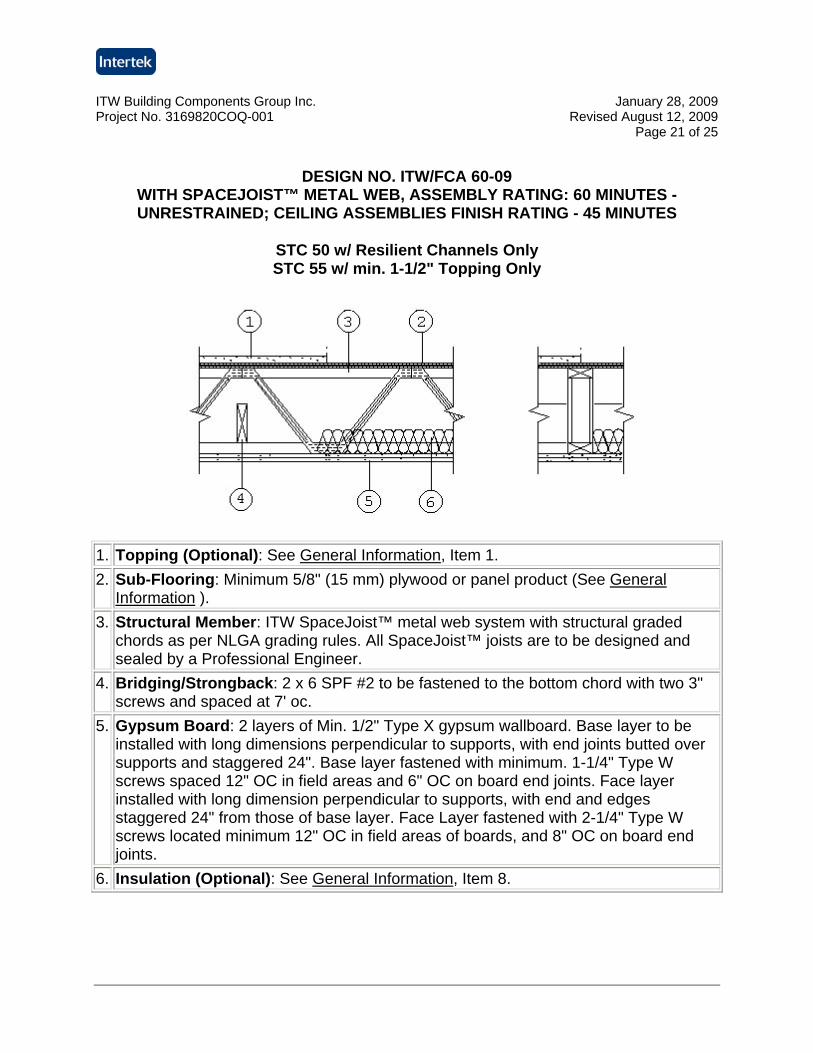
DESIGN NO. ITW/FCA 60-09
WITH SPACEJOIST™ METAL WEB, ASSEMBLY RATING: 60 MINUTES - UNRESTRAINED; CEILING ASSEMBLIES FINISH RATING - 45 MINUTES
STC 50 w/ Resilient Channels Only STC 55 w/ min. 1-1/2" Topping Only
1. Topping (Optional): See General Information, Item 1. 2. Sub-Flooring: Minimum 5/8" (15 mm) plywood or panel product (See General
Information ). 3. Structural Member: ITW SpaceJoist™ metal web system with structural graded
chords as per NLGA grading rules. All SpaceJoist™ joists are to be designed and sealed by a Professional Engineer.
4. Bridging/Strongback: 2 x 6 SPF #2 to be fastened to the bottom chord with two 3" screws and spaced at 7' oc.
5. Gypsum Board: 2 layers of Min. 1/2" Type X gypsum wallboard. Base layer to be installed with long dimensions perpendicular to supports, with end joints butted over supports and staggered 24". Base layer fastened with minimum. 1-1/4" Type W screws spaced 12" OC in field areas and 6" OC on board end joints. Face layer installed with long dimension perpendicular to supports, with end and edges staggered 24" from those of base layer. Face Layer fastened with 2-1/4" Type W screws located minimum 12" OC in field areas of boards, and 8" OC on board end joints.
6. Insulation (Optional): See General Information, Item 8.
ITW Building Components Group Inc. January 28, 2009 Project No. 3169820COQ-001 Revised August 12, 2009
Page 22 of 25
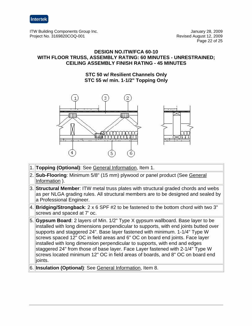
DESIGN NO.ITW/FCA 60-10 WITH FLOOR TRUSS, ASSEMBLY RATING: 60 MINUTES - UNRESTRAINED;
CEILING ASSEMBLY FINISH RATING - 45 MINUTES
STC 50 w/ Resilient Channels Only STC 55 w/ min. 1-1/2" Topping Only
1. Topping (Optional): See General Information, Item 1. 2. Sub-Flooring: Minimum 5/8" (15 mm) plywood or panel product (See General
Information ). 3. Structural Member: ITW metal truss plates with structural graded chords and webs
as per NLGA grading rules. All structural members are to be designed and sealed by a Professional Engineer.
4. Bridging/Strongback: 2 x 6 SPF #2 to be fastened to the bottom chord with two 3" screws and spaced at 7' oc.
5. Gypsum Board: 2 layers of Min. 1/2" Type X gypsum wallboard. Base layer to be installed with long dimensions perpendicular to supports, with end joints butted over supports and staggered 24". Base layer fastened with minimum. 1-1/4" Type W screws spaced 12" OC in field areas and 6" OC on board end joints. Face layer installed with long dimension perpendicular to supports, with end and edges staggered 24" from those of base layer. Face Layer fastened with 2-1/4" Type W screws located minimum 12" OC in field areas of boards, and 8" OC on board end joints.
6. Insulation (Optional): See General Information, Item 8.
ITW Building Components Group Inc. January 28, 2009 Project No. 3169820COQ-001 Revised August 12, 2009
Page 23 of 25
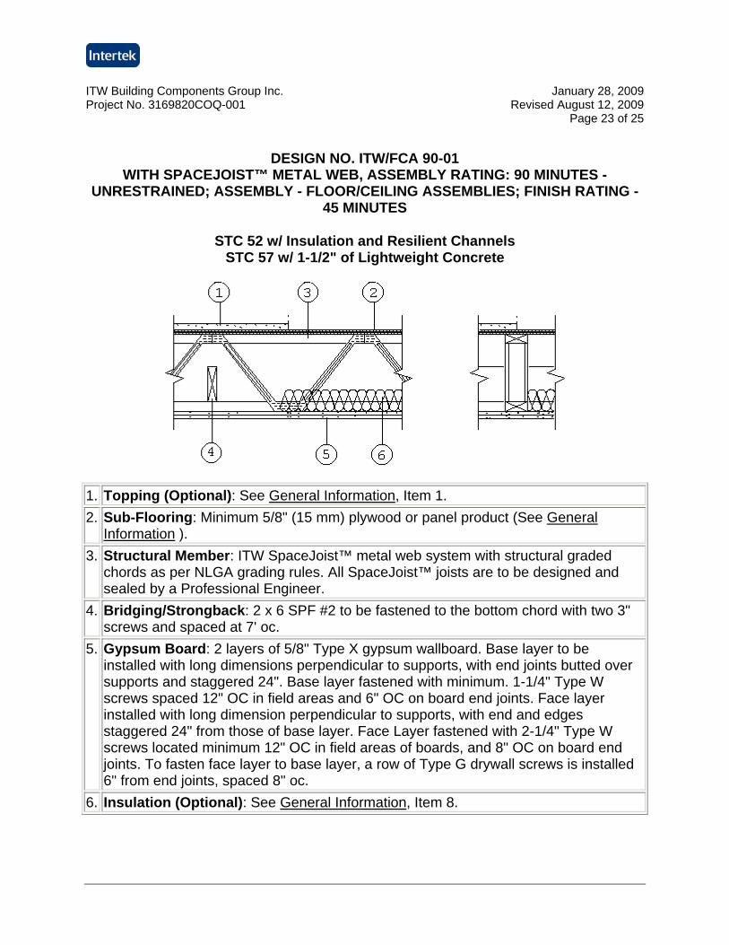
DESIGN NO. ITW/FCA 90-01
WITH SPACEJOIST™ METAL WEB, ASSEMBLY RATING: 90 MINUTES - UNRESTRAINED; ASSEMBLY - FLOOR/CEILING ASSEMBLIES; FINISH RATING -
45 MINUTES
STC 52 w/ Insulation and Resilient Channels STC 57 w/ 1-1/2" of Lightweight Concrete
1. Topping (Optional): See General Information, Item 1. 2. Sub-Flooring: Minimum 5/8" (15 mm) plywood or panel product (See General
Information ). 3. Structural Member: ITW SpaceJoist™ metal web system with structural graded
chords as per NLGA grading rules. All SpaceJoist™ joists are to be designed and sealed by a Professional Engineer.
4. Bridging/Strongback: 2 x 6 SPF #2 to be fastened to the bottom chord with two 3" screws and spaced at 7' oc.
5. Gypsum Board: 2 layers of 5/8" Type X gypsum wallboard. Base layer to be installed with long dimensions perpendicular to supports, with end joints butted over supports and staggered 24". Base layer fastened with minimum. 1-1/4" Type W screws spaced 12" OC in field areas and 6" OC on board end joints. Face layer installed with long dimension perpendicular to supports, with end and edges staggered 24" from those of base layer. Face Layer fastened with 2-1/4" Type W screws located minimum 12" OC in field areas of boards, and 8" OC on board end joints. To fasten face layer to base layer, a row of Type G drywall screws is installed 6" from end joints, spaced 8" oc.
6. Insulation (Optional): See General Information, Item 8.
ITW Building Components Group Inc. January 28, 2009 Project No. 3169820COQ-001 Revised August 12, 2009
Page 24 of 25
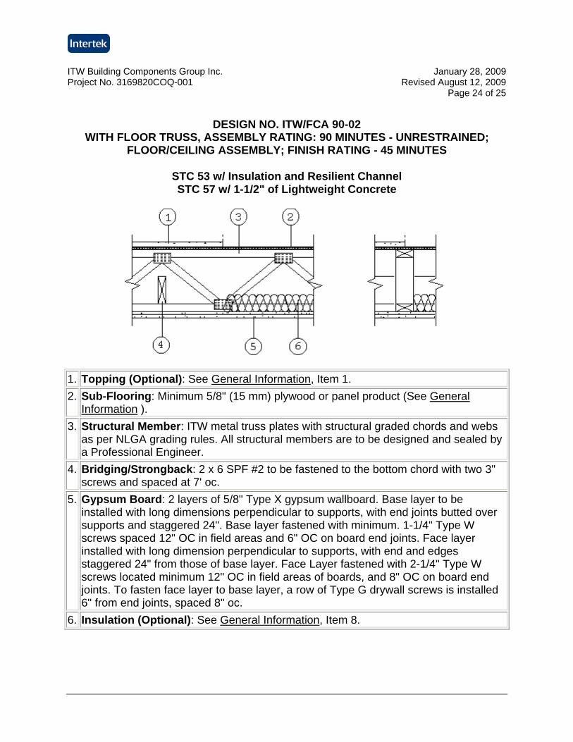
DESIGN NO. ITW/FCA 90-02
WITH FLOOR TRUSS, ASSEMBLY RATING: 90 MINUTES - UNRESTRAINED; FLOOR/CEILING ASSEMBLY; FINISH RATING - 45 MINUTES
STC 53 w/ Insulation and Resilient Channel STC 57 w/ 1-1/2" of Lightweight Concrete
1. Topping (Optional): See General Information, Item 1. 2. Sub-Flooring: Minimum 5/8" (15 mm) plywood or panel product (See General
Information ). 3. Structural Member: ITW metal truss plates with structural graded chords and webs
as per NLGA grading rules. All structural members are to be designed and sealed by a Professional Engineer.
4. Bridging/Strongback: 2 x 6 SPF #2 to be fastened to the bottom chord with two 3" screws and spaced at 7' oc.
5. Gypsum Board: 2 layers of 5/8" Type X gypsum wallboard. Base layer to be installed with long dimensions perpendicular to supports, with end joints butted over supports and staggered 24". Base layer fastened with minimum. 1-1/4" Type W screws spaced 12" OC in field areas and 6" OC on board end joints. Face layer installed with long dimension perpendicular to supports, with end and edges staggered 24" from those of base layer. Face Layer fastened with 2-1/4" Type W screws located minimum 12" OC in field areas of boards, and 8" OC on board end joints. To fasten face layer to base layer, a row of Type G drywall screws is installed 6" from end joints, spaced 8" oc.
6. Insulation (Optional): See General Information, Item 8.
ITW Building Components Group Inc. January 28, 2009 Project No. 3169820COQ-001 Revised August 12, 2009
Page 25 of 25
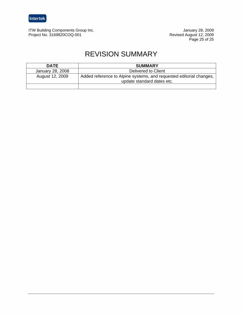
REVISION SUMMARY
DATE SUMMARY
January 28, 2008 Delivered to Client August 12, 2009 Added reference to Alpine systems, and requested editorial changes,
update standard dates etc.


![services[.] ' rendered[.] 2 - Louisiana](https://img.pdfslide.net/doc/110x75/619ca06f89aa0a236c37a0c9/services-rendered-2-louisiana.jpg)