Embed Size (px)
Citation preview
03.08 Andreas Hettich GmbH & Co. KG AR2080EN
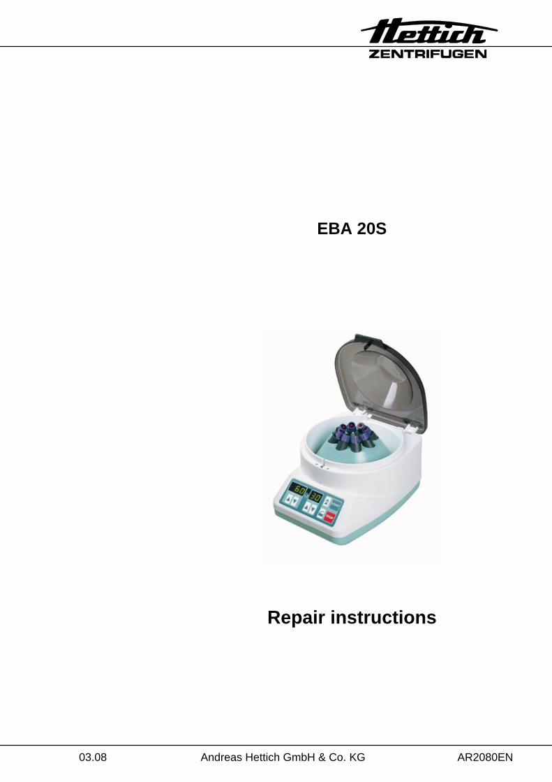
EBA 20S
Repair instructions
2/34
Andreas Hettich GmbH & Co. KG Föhrenstraße 12, D-78532 Tuttlingen / Germany Phone (07461) 705-0 Fax (07461) 705-125 [email protected], [email protected] www.hettichlab.com
© 2007 by Andreas Hettich GmbH & Co. KG
All rights reserved. No part of this publication may be reproduced without the prior written permission of the copyright owner.
Änderungen vorbehalten!
AR2080EN / 03.08
3/34
Contents 1 Introduction ..............................................................................................................5
2 Symbol meanings.....................................................................................................5
3 Description of the centrifuge.....................................................................................6 3.1 Control panel A3 ...............................................................................................7 3.2 Power board A1 ................................................................................................7 3.3 Motor M1...........................................................................................................8 3.4 Speed sensor B3...............................................................................................8 3.5 Brake resistor R1 and Overtemperature fuse F3...............................................8 3.6 Lid lock Y1 ........................................................................................................8 3.7 Imbalance switch S 2 ........................................................................................8
4 Troubleshooting procedures.....................................................................................9
5 Error messages......................................................................................................10 5.1 MAINS RESET................................................................................................10 5.2 Brief description ..............................................................................................10 5.3 Description and elimination of errors...............................................................11 5.4 Defects without Error indications.....................................................................16
6 Settings and enquiries............................................................................................18 6.1 Setting the machine version............................................................................18 6.2 Enquiry the machine version...........................................................................19 6.3 Enquiry the programme versions ....................................................................20 6.4 Brake adjustment ............................................................................................20 6.5 Lid lock control ................................................................................................21 6.6 Imbalance switch-off .......................................................................................21
7 Change mains input fuse........................................................................................22
8 Functional check after a repair ...............................................................................22
9 Assembling and disassembling components..........................................................23 9.1 Motor M1 / speed sensor B3 / Rubber-metal bearing......................................24 9.2 Power board A1 ..............................................................................................24 9.3 Control panel A3 ............................................................................................24 9.4 Brake resistor R1 ............................................................................................25 9.5 Overtemperature fuse F3 ................................................................................25 9.6 Flat ribbon cable..............................................................................................25 9.7 Appliance plug with mains switch....................................................................25 9.8 Imbalance switch S2 .......................................................................................25 9.9 Lid lock Y1 ......................................................................................................25
4/34
10 Circuit diagrams ................................................................................................. 26 10.1 Circuit diagram and plug assignment.............................................................. 27 10.2 Signals and test results................................................................................... 28
10.2.1 Speed sensor B3 (Tacho)........................................................................ 28 10.2.2 Motor ....................................................................................................... 28 10.2.3 Brake resistor R1 and overtemperature fuse F3...................................... 29 10.2.4 Lid lock Y1 ............................................................................................... 29 10.2.5 Imbalance switch ..................................................................................... 30 10.2.6 Intermediate voltage on power board A1................................................. 30
11 Technical specification ....................................................................................... 31
12 Skeleton construction of EBA 20S...................................................................... 32
13 Index .................................................................................................................. 33
5/34
1 Introduction • Repairs must only be carried out by personnel authorised to do so by the
manufacturer.
Interventions and modifications at centrifuges, which have been conducted by persons not authorized by the Andreas Hettich GmbH & Co. KGcompany, are at their own risk and entail the loss off all guarantee and liability claims. In such an event any guarantee claim or liability claim against the Andreas Hettich GmbH & Co. KG company expire.
• Only original spare parts and original accessories licensed by the Andreas Hettich GmbH & Co. KG company are allowed to be utilised.
If no original spare parts or no original accessories are used, any guarantee claim or liability claim against the Andreas Hettich GmbH & Co. KGcompany ceases to exist.
• Information about the operation of the centrifuge please see operating instructions. • We reserve all rights for these technical documents. 2 Symbol meanings
Symbol on the machine: Attention, general hazard area. Before using the centrifuge implicitly read the operating instructions and pay attention to the safety relevant references!
Symbol in this document: Attention, general hazard area. This symbol refers to safety relevant warnings and indicates possibly dangerous situations. The non-adherence to these warnings can lead to material damage and injury to personal.
Symbol in this document: Warning! Danger for human lives by electric shock.
Symbol in this document: This symbol refers to important circumstances.
Symbol on the machine and in this document: Symbol for the separate collection of electric and electronic devices according to the guideline 2002/96/EG (WEEE). The device belongs to Group 8 (medical devices). Applies in the countries of the European Union, as well as in Norway and Switzerland.
6/34
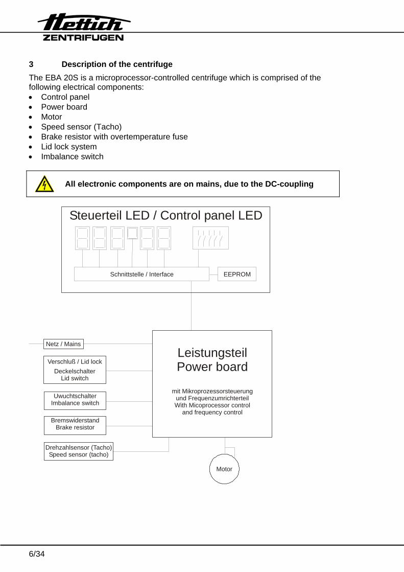
3 Description of the centrifuge The EBA 20S is a microprocessor-controlled centrifuge which is comprised of the following electrical components: • Control panel • Power board • Motor • Speed sensor (Tacho) • Brake resistor with overtemperature fuse • Lid lock system • Imbalance switch
All electronic components are on mains, due to the DC-coupling
Netz / Mains
Verschluß / Lid lockDeckelschalter
Lid switch
UwuchtschalterImbalance switch
BremswiderstandBrake resistor
Leistungsteil Power board
mit Mikroprozessorsteuerungund FrequenzumrichterteilWith Micoprocessor control
and frequency control
Steuerteil LED / Control panel LED
EEPROMSchnittstelle / Interface
Motor
Drehzahlsensor (Tacho)Speed sensor (tacho)
7/34
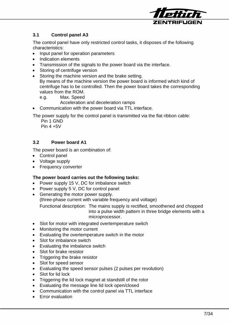
3.1 Control panel A3 The control panel have only restricted control tasks, it disposes of the following characteristics: • Input panel for operation parameters • Indication elements • Transmission of the signals to the power board via the interface. • Storing of centrifuge version • Storing the machine version and the brake setting.
By means of the machine version the power board is informed which kind of centrifuge has to be controlled. Then the power board takes the corresponding values from the ROM. e.g. Max. Speed Acceleration and deceleration ramps
• Communication with the power board via TTL interface. The power supply for the control panel is transmitted via the flat ribbon cable:
Pin 1 GND Pin 4 +5V
3.2 Power board A1 The power board is an combination of: • Control panel • Voltage supply • Frequency converter The power board carries out the following tasks: • Power supply 15 V, DC for imbalance switch • Power supply 5 V, DC for control panel • Generating the motor power supply.
(three-phase current with variable frequency and voltage) Functional description: The mains supply is rectified, smoothened and chopped
into a pulse width pattern in three bridge elements with a microprocessor.
• Slot for motor with integrated overtemperature switch • Monitoring the motor current • Evaluating the overtemperature switch in the motor • Slot for imbalance switch • Evaluating the imbalance switch • Slot for brake resistor • Triggering the brake resistor • Slot for speed sensor • Evaluating the speed sensor pulses (2 pulses per revolution) • Slot for lid lock • Triggering the lid lock magnet at standstill of the rotor • Evaluating the message line lid lock open/closed • Communication with the control panel via TTL interface • Error evaluation
8/34
3.3 Motor M1 • The motor is a three- phase asynchronous motor with two pairs of poles. • The motor is protected against overheating by an overtemperature switch. • The power board evaluates the overtemperature switch. • The motor is controlled by the power board with a three-phase current with variable
frequency and voltage. 3.4 Speed sensor B3 • The speed sensor (speedometer) is located at the bottom of the motor. • The speed signal (2 pulses per revolution) will be triggered by two magnets fixed at
the motor axle. • The speed of the rotor is monitored and controlled by the power board. 3.5 Brake resistor R1 and Overtemperature fuse F3 • The braking copper which is integrated on the power board transfers the electrical
energy produced during braking, from a voltage of 380 V with the 230 V version and 203 V with the 120 V version, to the brake resistor in a controlled manner.
• An overtemperature fuse protects the brake resistor against overheating. When the overtemperature fuse (F3) blows, the power board will be separated from the power supply.
3.6 Lid lock Y1 • Opening of the lid lock is prevented by a latch. The lid lock can only be opened when
the relay REL 602 on the power board is energised. This occurs when the rotor is at standstill, mains power is applied and the key is pressed. The solenoid is ener-gized for three seconds and releases the latch.
• The centrifuge can only be started when the lid is closed. A microswitch on the lid lock detects the position of the lid lock (open/closed) and report it to the power board.
3.7 Imbalance switch S 2 • A switch detects any imbalance. • Imbalance can only be detected in running mode (starting, centrifuging and braking). • If any imbalance is detected, the drive is changed over to braking.
9/34
4 Troubleshooting procedures • Fuses in installation in which centrifuge is installed are intact. • Mains input fuses of centrifuge are intact. • Supply voltage present at (see circuit diagram):
− Connecting cable − Appliance plug − Mains switch − Power board A1, plug S402L and S402N
• Look for the displayed error code in the chapter "Error messages". • Remedy the error according to the instructions. • Carry out a functional check after every repair and whenever a component is
replaced, see chapter "Functional check after a repair".
10/34
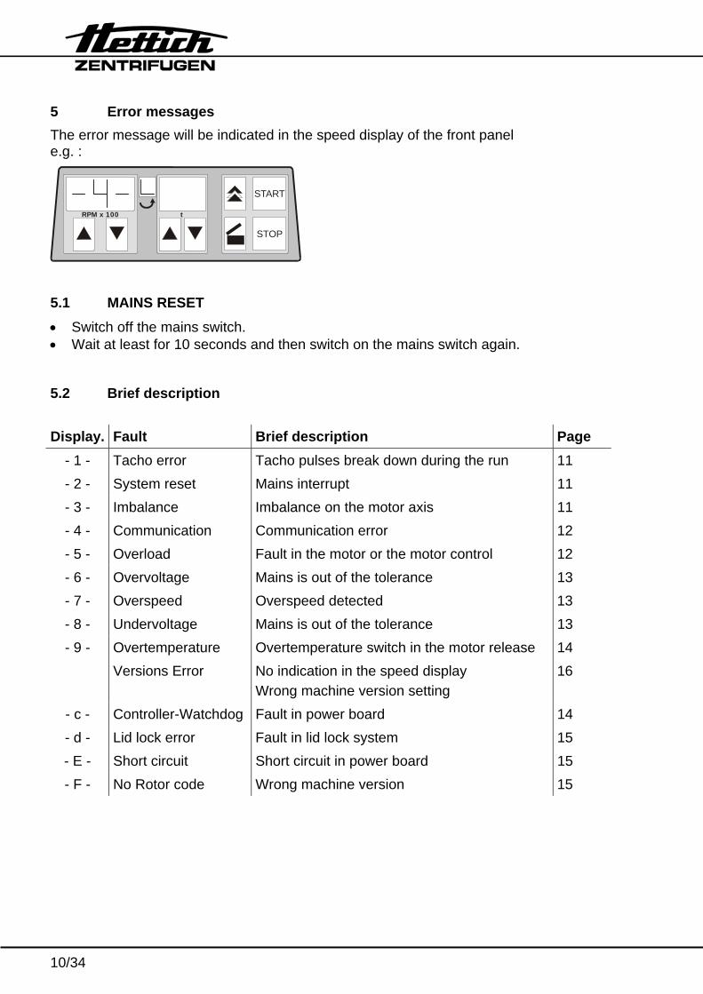
5 Error messages The error message will be indicated in the speed display of the front panel e.g. :
RPM x 100 t
START
STOP
5.1 MAINS RESET • Switch off the mains switch. • Wait at least for 10 seconds and then switch on the mains switch again. 5.2 Brief description Display. Fault Brief description Page
- 1 - Tacho error Tacho pulses break down during the run 11 - 2 - System reset Mains interrupt 11 - 3 - Imbalance Imbalance on the motor axis 11 - 4 - Communication Communication error 12 - 5 - Overload Fault in the motor or the motor control 12 - 6 - Overvoltage Mains is out of the tolerance 13 - 7 - Overspeed Overspeed detected 13 - 8 - Undervoltage Mains is out of the tolerance 13 - 9 - Overtemperature Overtemperature switch in the motor release 14
Versions Error No indication in the speed display Wrong machine version setting
16
- c - Controller-Watchdog Fault in power board 14 - d - Lid lock error Fault in lid lock system 15 - E - Short circuit Short circuit in power board 15 - F - No Rotor code Wrong machine version 15
11/34
5.3 Description and elimination of errors – 1 – Tacho error Error Tacho pulses break down during the run. Error consequence
Drive switch off and brakes with the adjusted brake level.
Error cause • Speed sensor (tacho) defective • Power board (A1) defective • Loosen contact in plug S502
Measurement 1. A1 / S502 pin 2 (GND) to pin 3 (+UB) 2. Speed sensor plug S502 , pin 4 – pin 2 GND (2 pulses per
revolution). See also section 10.2 Error code reset Wait for a time duration of 120 sec. and after this perform a MAINS
RESET. – 2 – System reset Error Mains interrupt during a run Error consequence
Drive switch off and brakes with the adjusted brake level.
Error cause • Power supply has failed • Loosen contact in electrical connections
Error code reset 1. Wait for rotor standstill 2. Open the lid and press key START
or perform a MAINS RESET
12/34
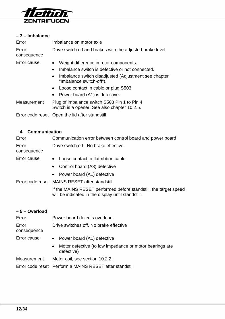
– 3 – Imbalance Error Imbalance on motor axle Error consequence
Drive switch off and brakes with the adjusted brake level
Error cause • Weight difference in rotor components. • Imbalance switch is defective or not connected. • Imbalance switch disadjusted (Adjustment see chapter
"Imbalance switch-off"). • Loose contact in cable or plug S503 • Power board (A1) is defective.
Measurement Plug of imbalance switch S503 Pin 1 to Pin 4 Switch is a opener. See also chapter 10.2.5.
Error code reset Open the lid after standstill – 4 – Communication Error Communication error between control board and power board Error consequence
Drive switch off . No brake effective
Error cause • Loose contact in flat ribbon cable
• Control board (A3) defective
• Power board (A1) defective Error code reset MAINS RESET after standstill.
If the MAINS RESET performed before standstill, the target speed will be indicated in the display until standstill.
– 5 – Overload Error Power board detects overload Error consequence
Drive switches off. No brake effective
Error cause • Power board (A1) defective
• Motor defective (to low impedance or motor bearings are defective)
Measurement Motor coil, see section 10.2.2. Error code reset Perform a MAINS RESET after standstill
13/34
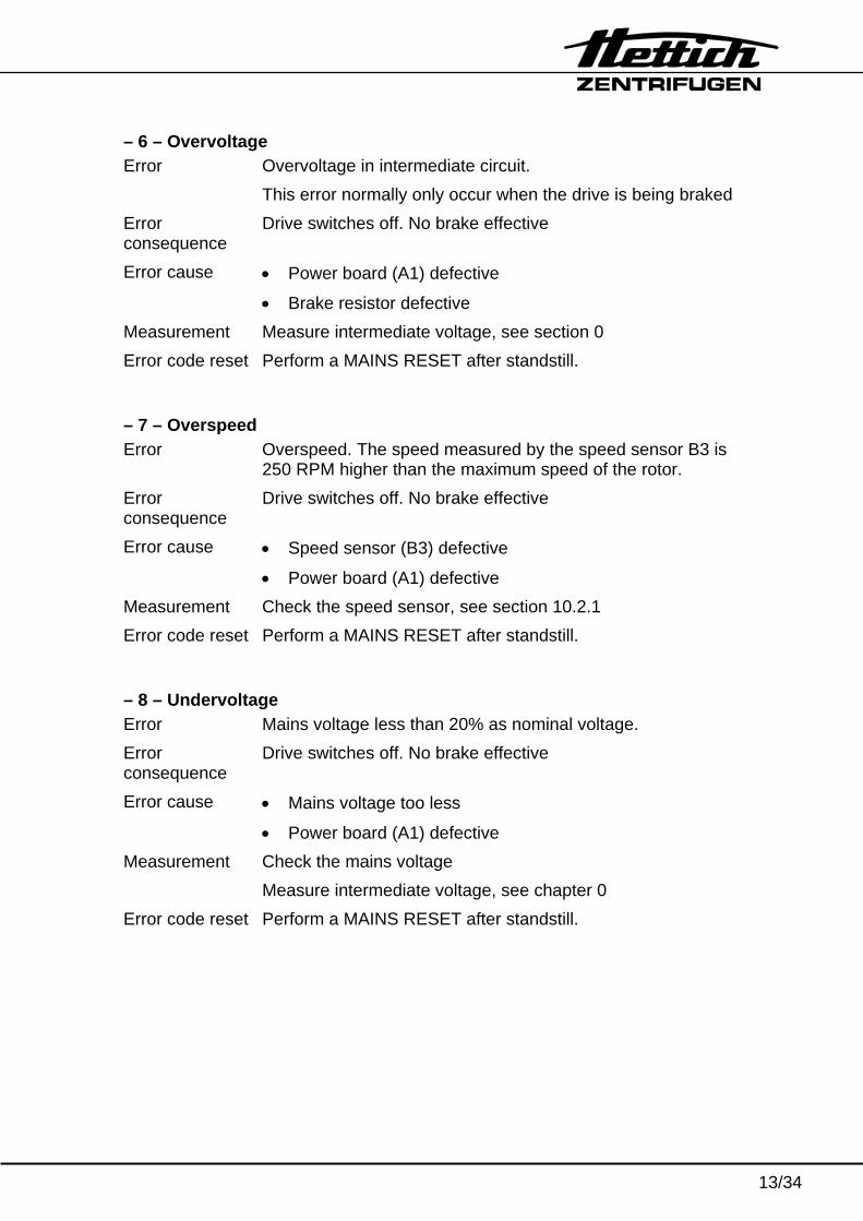
– 6 – Overvoltage Error Overvoltage in intermediate circuit.
This error normally only occur when the drive is being braked Error consequence
Drive switches off. No brake effective
Error cause • Power board (A1) defective
• Brake resistor defective Measurement Measure intermediate voltage, see section 0 Error code reset Perform a MAINS RESET after standstill. – 7 – Overspeed Error Overspeed. The speed measured by the speed sensor B3 is
250 RPM higher than the maximum speed of the rotor. Error consequence
Drive switches off. No brake effective
Error cause • Speed sensor (B3) defective
• Power board (A1) defective Measurement Check the speed sensor, see section 10.2.1 Error code reset Perform a MAINS RESET after standstill. – 8 – Undervoltage Error Mains voltage less than 20% as nominal voltage. Error consequence
Drive switches off. No brake effective
Error cause • Mains voltage too less
• Power board (A1) defective Measurement Check the mains voltage
Measure intermediate voltage, see chapter 0 Error code reset Perform a MAINS RESET after standstill.
14/34
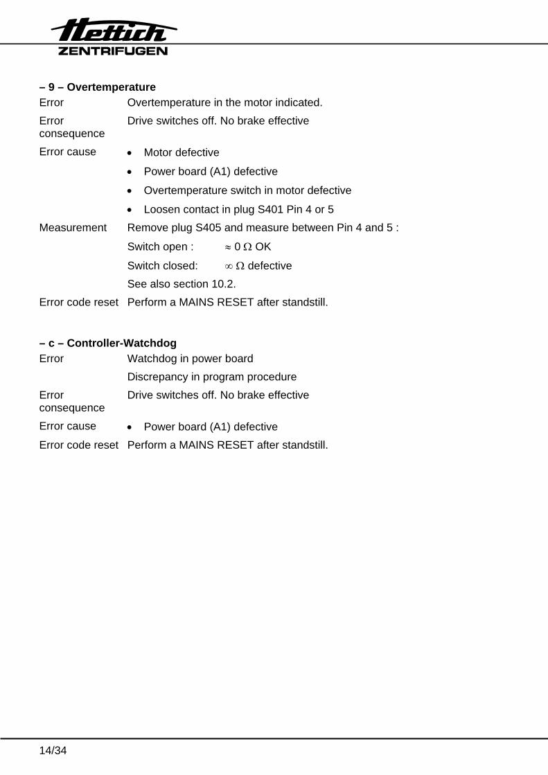
– 9 – Overtemperature Error Overtemperature in the motor indicated. Error consequence
Drive switches off. No brake effective
Error cause • Motor defective
• Power board (A1) defective
• Overtemperature switch in motor defective
• Loosen contact in plug S401 Pin 4 or 5 Measurement Remove plug S405 and measure between Pin 4 and 5 :
Switch open : ≈ 0 Ω OK
Switch closed: ∞ Ω defective See also section 10.2.
Error code reset Perform a MAINS RESET after standstill. – c – Controller-Watchdog Error Watchdog in power board
Discrepancy in program procedure Error consequence
Drive switches off. No brake effective
Error cause • Power board (A1) defective Error code reset Perform a MAINS RESET after standstill.
15/34
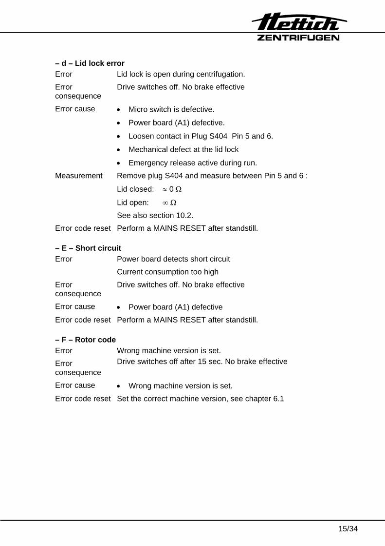
– d – Lid lock error Error Lid lock is open during centrifugation. Error consequence
Drive switches off. No brake effective
Error cause • Micro switch is defective.
• Power board (A1) defective.
• Loosen contact in Plug S404 Pin 5 and 6.
• Mechanical defect at the lid lock
• Emergency release active during run. Measurement Remove plug S404 and measure between Pin 5 and 6 :
Lid closed: ≈ 0 Ω
Lid open: ∞ Ω See also section 10.2.
Error code reset Perform a MAINS RESET after standstill. – E – Short circuit Error Power board detects short circuit
Current consumption too high Error consequence
Drive switches off. No brake effective
Error cause • Power board (A1) defective Error code reset Perform a MAINS RESET after standstill. – F – Rotor code Error Wrong machine version is set. Error consequence
Drive switches off after 15 sec. No brake effective
Error cause • Wrong machine version is set. Error code reset Set the correct machine version, see chapter 6.1
16/34
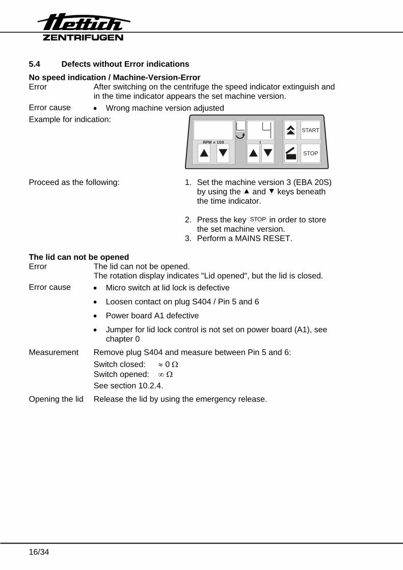
5.4 Defects without Error indications No speed indication / Machine-Version-Error Error After switching on the centrifuge the speed indicator extinguish and
in the time indicator appears the set machine version. Error cause • Wrong machine version adjusted Example for indication:
RPM x 100 t
START
STOP
Proceed as the following: 1. Set the machine version 3 (EBA 20S) by using the and keys beneath the time indicator.
2. Press the key STOP in order to store
the set machine version. 3. Perform a MAINS RESET. The lid can not be opened Error The lid can not be opened.
The rotation display indicates "Lid opened", but the lid is closed. Error cause • Micro switch at lid lock is defective
• Loosen contact on plug S404 / Pin 5 and 6
• Power board A1 defective
• Jumper for lid lock control is not set on power board (A1), see chapter 0
Measurement Remove plug S404 and measure between Pin 5 and 6: Switch closed: ≈ 0 Ω Switch opened: ∞ Ω See section 10.2.4.
Opening the lid Release the lid by using the emergency release.
17/34
The lid can not be opened Error The lid can not be opened
The rotation display indicates "Lid closed" and the lid is closed. Error cause • Solenoid on lid lock is defective
• Loosen contact on plug S404 / Pin 1 and 3
• Power board A1 defective
• Jumper for lid lock control is set on power board (A1), see chapter 0
Measurement Remove plug S404 and measure between Pin 1 and 3 : Solenoid ok: ≈ 5.7 kΩ Solenoid defective: ∞ Ω See also section 10.2.4.
Opening the lid Release the lid by using the emergency release. No display
Error No power supply on control board, no display Error consequence
No operation possible
Error cause • No mains supply
• Power board (A1) defective
• Control panel (A3) defective
• Flat ribbon cable to control panel (A3) defective
• Overtemperature fuse F3 defective Measurement 1. Mains supply power board A1 S402L to S402N
2. Power board A1 S501 Pin 1 (GND) to S501 Pin 4 (+5V) 3. Control panel A3 S502 Pin 1 (GND) to S502 Pin 4 (+5V) 4. Overtemperature fuse F3. Remove plug S405 and measure
directly at both flat connections of the overtemperature fuse: Fuse OK : ≈ 0 Ω Fuse defective: ∞ Ω. See also section 10.2.3.
18/34
6 Settings and enquiries
RPM x 100 t
START
STOP
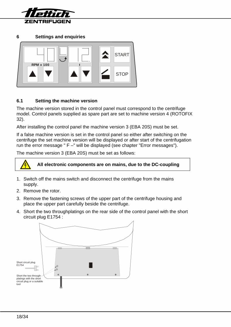
6.1 Setting the machine version The machine version stored in the control panel must correspond to the centrifuge model. Control panels supplied as spare part are set to machine version 4 (ROTOFIX 32). After installing the control panel the machine version 3 (EBA 20S) must be set. If a false machine version is set in the control panel so either after switching on the centrifuge the set machine version will be displayed or after start of the centrifugation run the error message " F –" will be displayed (see chapter "Error messages"). The machine version 3 (EBA 20S) must be set as follows:
All electronic components are on mains, due to the DC-coupling
1. Switch off the mains switch and disconnect the centrifuge from the mains
supply. 2. Remove the rotor. 3. Remove the fastening screws of the upper part of the centrifuge housing and
place the upper part carefully beside the centrifuge. 4. Short the two throughplatings on the rear side of the control panel with the short
circuit plug E1754 :
Short circuit plugE1754
Short the two through-platings with the shortcircuit plug or a suitabletool
19/34
5. Put on carefully the upper centrifuge housing. 6. Connect the centrifuge to the mains and switch the centrifuge on. 7. Switch on the mains switch (position "I").
The set machine version will be displayed, e.g.:
RPM x 100 t
START
STOP
8. Adjust the machine version 3 by using the and keys beneath the time
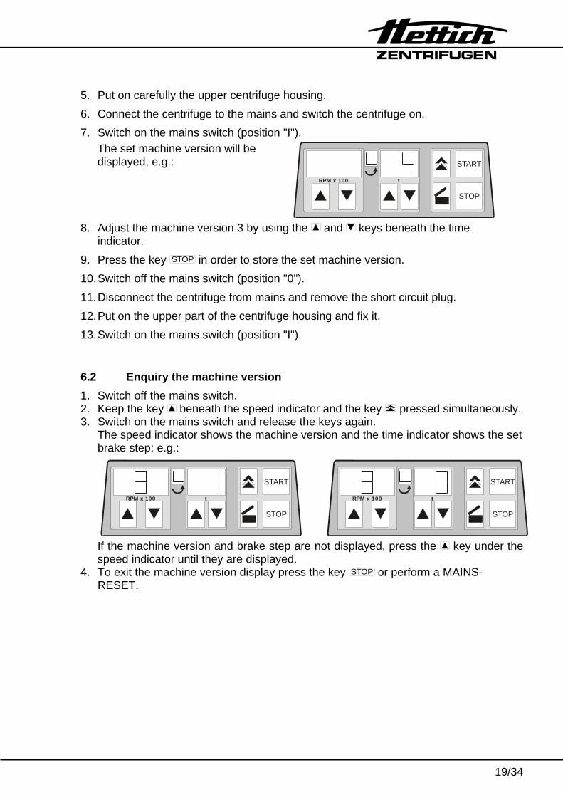
indicator. 9. Press the key STOP in order to store the set machine version. 10. Switch off the mains switch (position "0"). 11. Disconnect the centrifuge from mains and remove the short circuit plug. 12. Put on the upper part of the centrifuge housing and fix it. 13. Switch on the mains switch (position "I"). 6.2 Enquiry the machine version 1. Switch off the mains switch. 2. Keep the key beneath the speed indicator and the key pressed simultaneously. 3. Switch on the mains switch and release the keys again.
The speed indicator shows the machine version and the time indicator shows the set brake step: e.g.:
RPM x 100 t
START
STOP
RPM x 100 t
START
STOP
If the machine version and brake step are not displayed, press the key under the speed indicator until they are displayed.
4. To exit the machine version display press the key STOP or perform a MAINS-RESET.
20/34
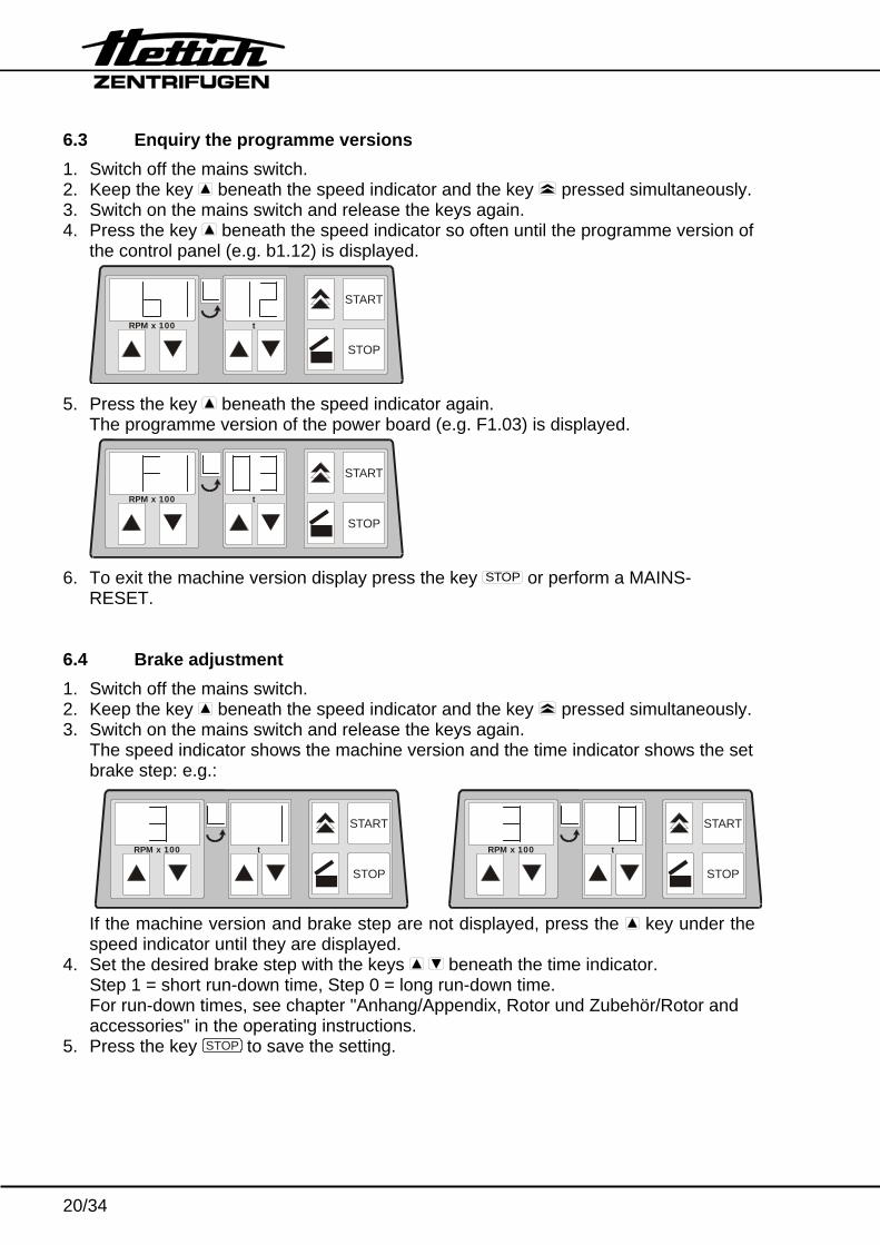
6.3 Enquiry the programme versions 1. Switch off the mains switch. 2. Keep the key beneath the speed indicator and the key pressed simultaneously. 3. Switch on the mains switch and release the keys again. 4. Press the key beneath the speed indicator so often until the programme version of
the control panel (e.g. b1.12) is displayed.
RPM x 100 t
START
STOP
5. Press the key beneath the speed indicator again.
The programme version of the power board (e.g. F1.03) is displayed.
RPM x 100 t
START
STOP
6. To exit the machine version display press the key STOP or perform a MAINS-
RESET. 6.4 Brake adjustment 1. Switch off the mains switch. 2. Keep the key beneath the speed indicator and the key pressed simultaneously. 3. Switch on the mains switch and release the keys again.
The speed indicator shows the machine version and the time indicator shows the set brake step: e.g.:
RPM x 100 t
START
STOP
RPM x 100 t
START
STOP
If the machine version and brake step are not displayed, press the key under the speed indicator until they are displayed.
4. Set the desired brake step with the keys beneath the time indicator. Step 1 = short run-down time, Step 0 = long run-down time. For run-down times, see chapter "Anhang/Appendix, Rotor und Zubehör/Rotor and accessories" in the operating instructions.
5. Press the key STOP to save the setting.
21/34
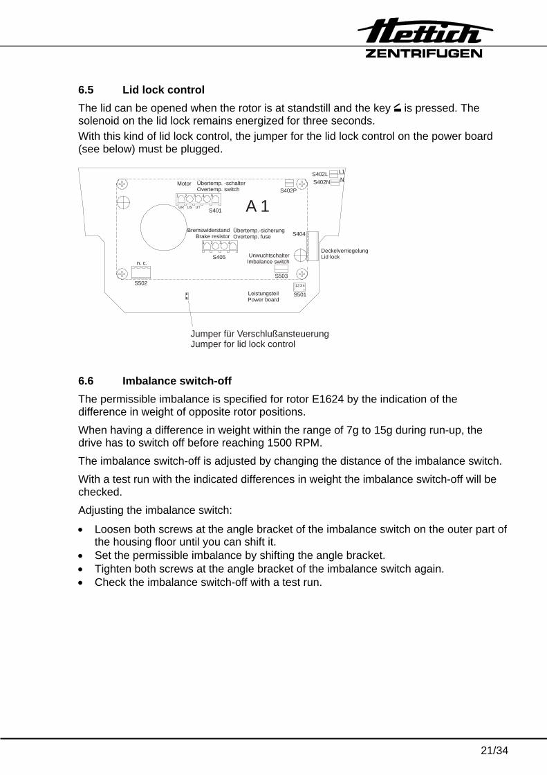
6.5 Lid lock control The lid can be opened when the rotor is at standstill and the key is pressed. The solenoid on the lid lock remains energized for three seconds. With this kind of lid lock control, the jumper for the lid lock control on the power board (see below) must be plugged.
Jumper für VerschlußansteuerungJumper for lid lock control
LeistungsteilPower board
UnwuchtschalterImbalance switch
DeckelverriegelungLid lock
Motor Übertemp. -schalterOvertemp. switch
Übertemp.-sicherungOvertemp. fuse
BremswiderstandBrake resistor
S402LS402N
L1N
S402P
A 1S404
S503
S501
2 3 41
S405
1 2 3 4
S502
S401UR US UT
1 2 3 4 5
n. c.
6.6 Imbalance switch-off The permissible imbalance is specified for rotor E1624 by the indication of the difference in weight of opposite rotor positions. When having a difference in weight within the range of 7g to 15g during run-up, the drive has to switch off before reaching 1500 RPM. The imbalance switch-off is adjusted by changing the distance of the imbalance switch. With a test run with the indicated differences in weight the imbalance switch-off will be checked. Adjusting the imbalance switch:
• Loosen both screws at the angle bracket of the imbalance switch on the outer part of the housing floor until you can shift it.
• Set the permissible imbalance by shifting the angle bracket. • Tighten both screws at the angle bracket of the imbalance switch again. • Check the imbalance switch-off with a test run.
22/34
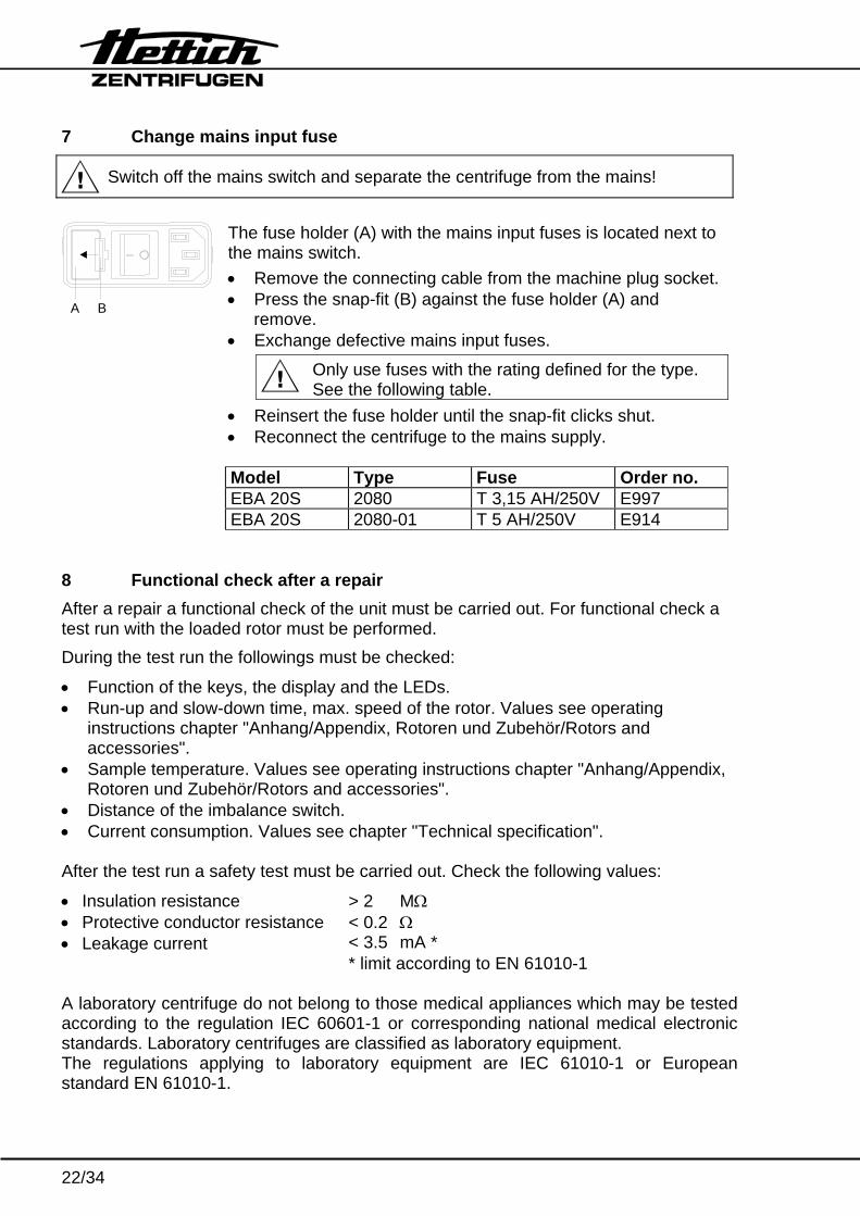
7 Change mains input fuse
Switch off the mains switch and separate the centrifuge from the mains!
The fuse holder (A) with the mains input fuses is located next to the mains switch. • Remove the connecting cable from the machine plug socket.• Press the snap-fit (B) against the fuse holder (A) and
remove. • Exchange defective mains input fuses.
A B
Only use fuses with the rating defined for the type. See the following table.
• Reinsert the fuse holder until the snap-fit clicks shut. • Reconnect the centrifuge to the mains supply.
Model Type Fuse Order no. EBA 20S 2080 T 3,15 AH/250V E997 EBA 20S 2080-01 T 5 AH/250V E914 8 Functional check after a repair After a repair a functional check of the unit must be carried out. For functional check a test run with the loaded rotor must be performed. During the test run the followings must be checked:
• Function of the keys, the display and the LEDs. • Run-up and slow-down time, max. speed of the rotor. Values see operating
instructions chapter "Anhang/Appendix, Rotoren und Zubehör/Rotors and accessories".
• Sample temperature. Values see operating instructions chapter "Anhang/Appendix, Rotoren und Zubehör/Rotors and accessories".
• Distance of the imbalance switch. • Current consumption. Values see chapter "Technical specification". After the test run a safety test must be carried out. Check the following values:
• Insulation resistance > 2 MΩ • Protective conductor resistance < 0.2 Ω • Leakage current < 3.5 mA * * limit according to EN 61010-1 A laboratory centrifuge do not belong to those medical appliances which may be tested according to the regulation IEC 60601-1 or corresponding national medical electronic standards. Laboratory centrifuges are classified as laboratory equipment. The regulations applying to laboratory equipment are IEC 61010-1 or European standard EN 61010-1.
23/34
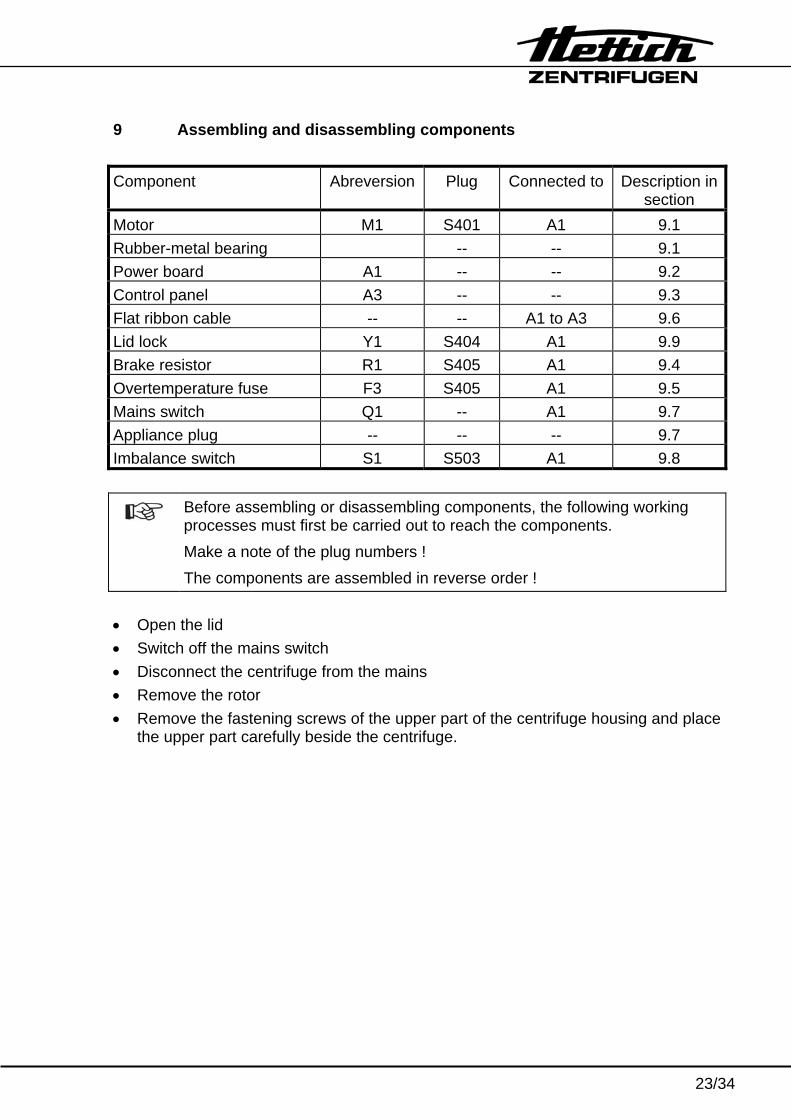
9 Assembling and disassembling components Component Abreversion Plug Connected to Description in
section Motor M1 S401 A1 9.1 Rubber-metal bearing -- -- 9.1 Power board A1 -- -- 9.2 Control panel A3 -- -- 9.3 Flat ribbon cable -- -- A1 to A3 9.6 Lid lock Y1 S404 A1 9.9 Brake resistor R1 S405 A1 9.4 Overtemperature fuse F3 S405 A1 9.5 Mains switch Q1 -- A1 9.7 Appliance plug -- -- -- 9.7 Imbalance switch S1 S503 A1 9.8
Before assembling or disassembling components, the following working processes must first be carried out to reach the components. Make a note of the plug numbers ! The components are assembled in reverse order !
• Open the lid • Switch off the mains switch • Disconnect the centrifuge from the mains • Remove the rotor • Remove the fastening screws of the upper part of the centrifuge housing and place
the upper part carefully beside the centrifuge.
24/34
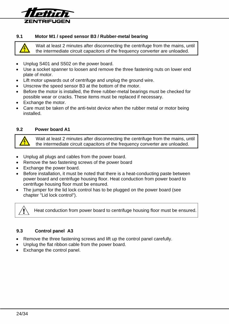
9.1 Motor M1 / speed sensor B3 / Rubber-metal bearing
Wait at least 2 minutes after disconnecting the centrifuge from the mains, until the intermediate circuit capacitors of the frequency converter are unloaded.
• Unplug S401 and S502 on the power board. • Use a socket spanner to loosen and remove the three fastening nuts on lower end
plate of motor. • Lift motor upwards out of centrifuge and unplug the ground wire. • Unscrew the speed sensor B3 at the bottom of the motor. • Before the motor is installed, the three rubber-metal bearings must be checked for
possible wear or cracks. These items must be replaced if necessary. • Exchange the motor. • Care must be taken of the anti-twist device when the rubber metal or motor being
installed. 9.2 Power board A1
Wait at least 2 minutes after disconnecting the centrifuge from the mains, until the intermediate circuit capacitors of the frequency converter are unloaded.
• Unplug all plugs and cables from the power board. • Remove the two fastening screws of the power board • Exchange the power board. • Before installation, it must be noted that there is a heat-conducting paste between
power board and centrifuge housing floor. Heat conduction from power board to centrifuge housing floor must be ensured.
• The jumper for the lid lock control has to be plugged on the power board (see chapter "Lid lock control").
Heat conduction from power board to centrifuge housing floor must be ensured.
9.3 Control panel A3 • Remove the three fastening screws and lift up the control panel carefully. • Unplug the flat ribbon cable from the power board. • Exchange the control panel.
25/34
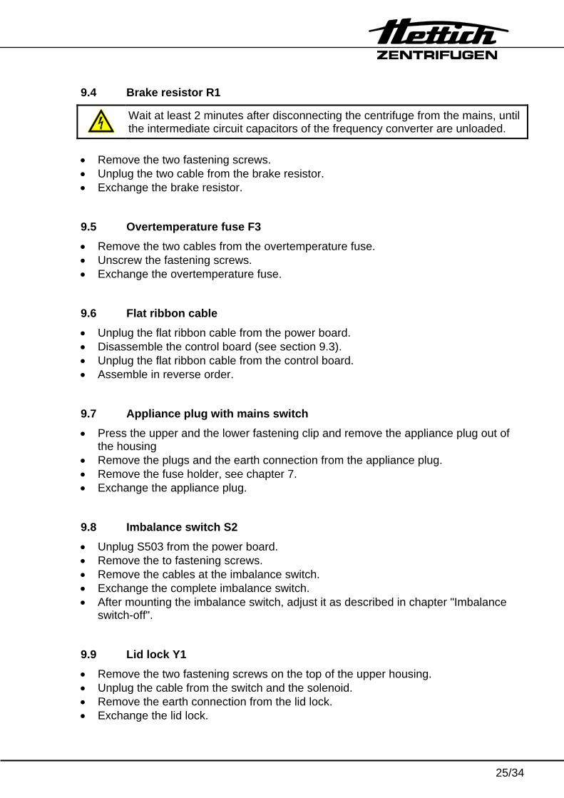
9.4 Brake resistor R1
Wait at least 2 minutes after disconnecting the centrifuge from the mains, until the intermediate circuit capacitors of the frequency converter are unloaded.
• Remove the two fastening screws. • Unplug the two cable from the brake resistor. • Exchange the brake resistor. 9.5 Overtemperature fuse F3 • Remove the two cables from the overtemperature fuse. • Unscrew the fastening screws. • Exchange the overtemperature fuse. 9.6 Flat ribbon cable • Unplug the flat ribbon cable from the power board. • Disassemble the control board (see section 9.3). • Unplug the flat ribbon cable from the control board. • Assemble in reverse order. 9.7 Appliance plug with mains switch • Press the upper and the lower fastening clip and remove the appliance plug out of
the housing • Remove the plugs and the earth connection from the appliance plug. • Remove the fuse holder, see chapter 7. • Exchange the appliance plug. 9.8 Imbalance switch S2 • Unplug S503 from the power board. • Remove the to fastening screws. • Remove the cables at the imbalance switch. • Exchange the complete imbalance switch. • After mounting the imbalance switch, adjust it as described in chapter "Imbalance
switch-off". 9.9 Lid lock Y1 • Remove the two fastening screws on the top of the upper housing. • Unplug the cable from the switch and the solenoid. • Remove the earth connection from the lid lock. • Exchange the lid lock.
26/34
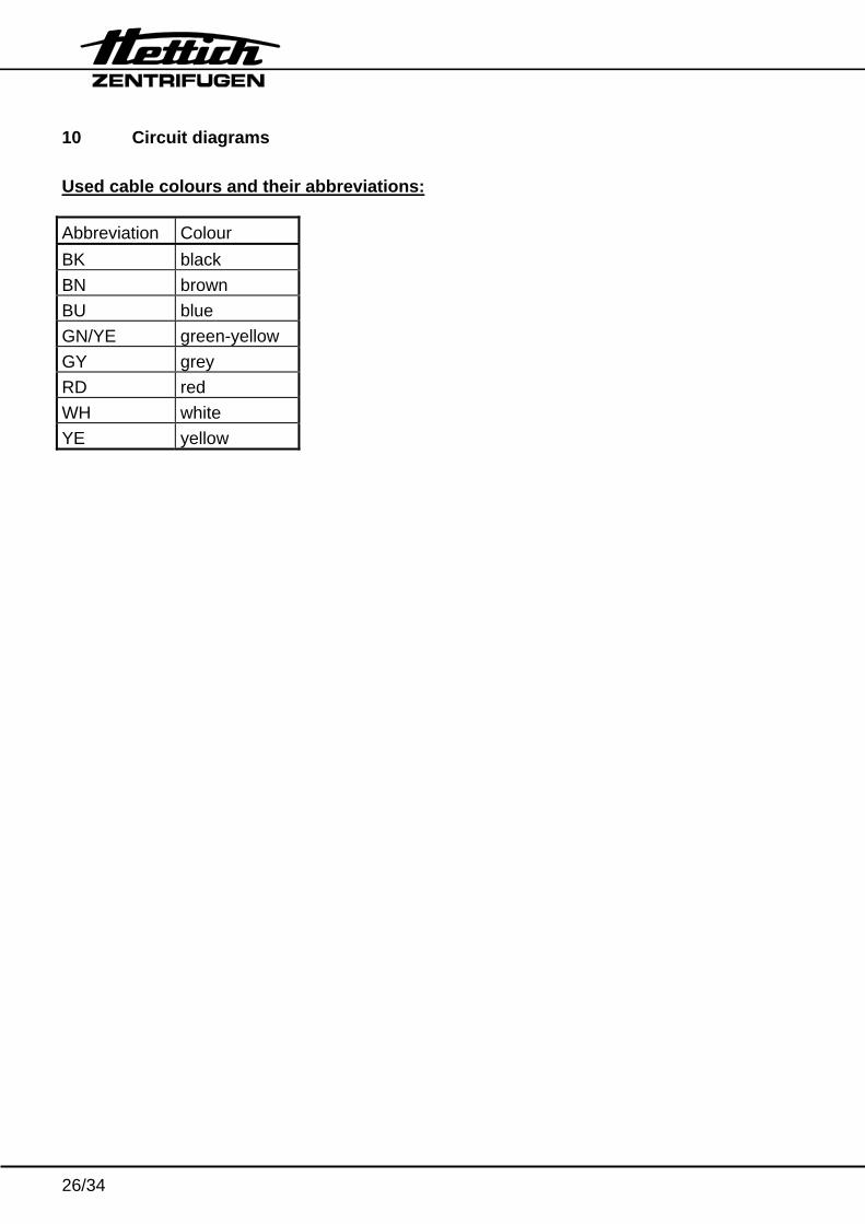
10 Circuit diagrams Used cable colours and their abbreviations: Abbreviation Colour BK black BN brown BU blue GN/YE green-yellow GY grey RD red WH white YE yellow
27/34
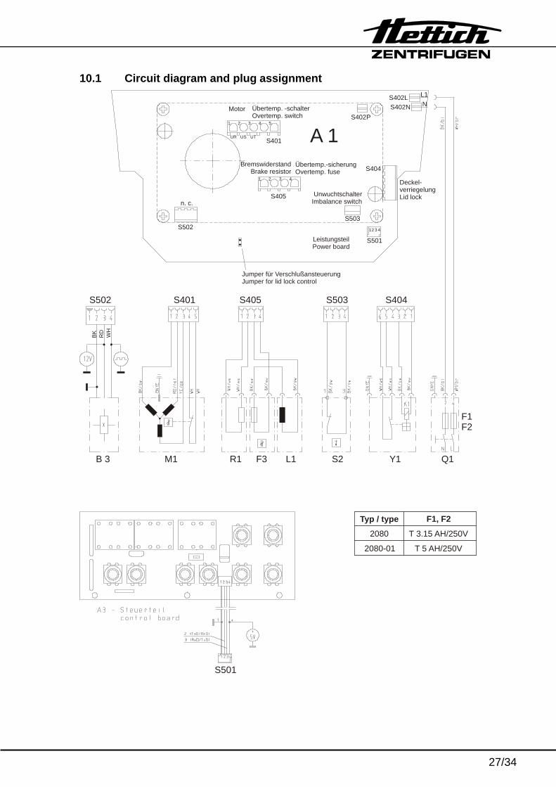
10.1 Circuit diagram and plug assignment
M1 R1 F3 L1 S2 Y1 Q1
S401 S405 S503 S404
S501
Jumper für VerschlußansteuerungJumper for lid lock control
LeistungsteilPower board
UnwuchtschalterImbalance switch
Deckel-verriegelungLid lock
Motor Übertemp. -schalterOvertemp. switch
Übertemp.-sicherungOvertemp. fuse
BremswiderstandBrake resistor
S402LS402N
L1N
S402P
A 1S404
S503
S501
2 3 41
S405
1 2 3 4
S502
S401UR US UT
1 2 3 4 5
n. c.
B 3
S502
BK RD
WH
F1, F2
2080
2080-01
T 3.15 AH/250V
T 5 AH/250V
Typ / type
F1F2
28/34
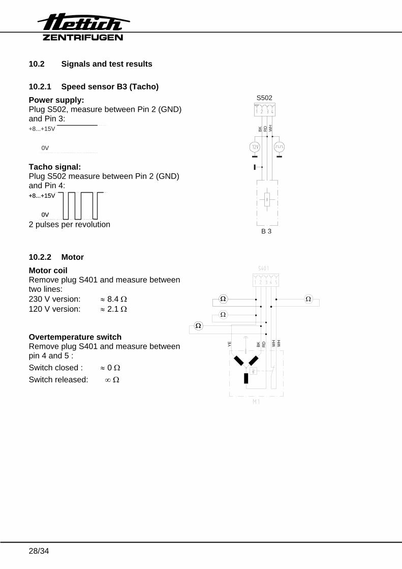
10.2 Signals and test results 10.2.1 Speed sensor B3 (Tacho) Power supply: Plug S502, measure between Pin 2 (GND) and Pin 3: +8...+15V
0V Tacho signal: Plug S502 measure between Pin 2 (GND) and Pin 4: +8...+15V
0V
+8...+15V
0V 2 pulses per revolution
B 3
S502
BK RD
WH
10.2.2 Motor Motor coil Remove plug S401 and measure between two lines: 230 V version: ≈ 8.4 Ω 120 V version: ≈ 2.1 Ω Overtemperature switch Remove plug S401 and measure between pin 4 and 5 : Switch closed : ≈ 0 Ω Switch released: ∞ Ω
ΩΩ
Ω
ΩΩ
Ω
YE
BK
RD WH
WH
29/34
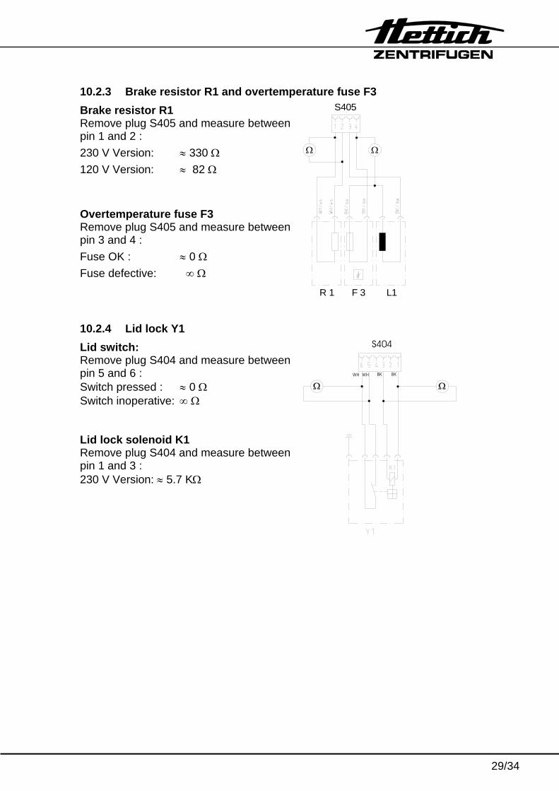
10.2.3 Brake resistor R1 and overtemperature fuse F3 Brake resistor R1 Remove plug S405 and measure between pin 1 and 2 : 230 V Version: ≈ 330 Ω 120 V Version: ≈ 82 Ω Overtemperature fuse F3 Remove plug S405 and measure between pin 3 and 4 : Fuse OK : ≈ 0 Ω Fuse defective: ∞ Ω L1R 1 F 3
S405
Ω Ω
10.2.4 Lid lock Y1 Lid switch: Remove plug S404 and measure between pin 5 and 6 : Switch pressed : ≈ 0 Ω Switch inoperative: ∞ Ω Lid lock solenoid K1 Remove plug S404 and measure between pin 1 and 3 : 230 V Version: ≈ 5.7 KΩ
S404
BKWH WH BK
30/34
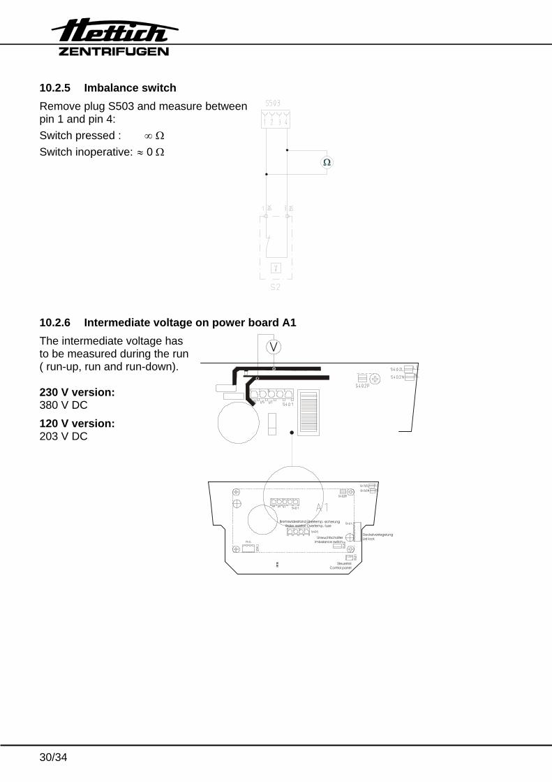
10.2.5 Imbalance switch Remove plug S503 and measure between pin 1 and pin 4: Switch pressed : ∞ Ω Switch inoperative: ≈ 0 Ω
10.2.6 Intermediate voltage on power board A1 The intermediate voltage has to be measured during the run ( run-up, run and run-down). 230 V version: 380 V DC 120 V version: 203 V DC
SteuerteilControl panel
UnwuchtschalterImbalance switch
DeckelverriegelungLid lock
Übertemp.-sicherungOvertemp. fuse
BremswiderstandBrake resistorr
n.c.
V
31/34
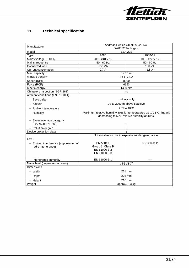
11 Technical specification
Manufacturer Andreas Hettich GmbH & Co. KG D-78532 Tuttlingen
Model EBA 20S Type 2080 2080-01 Mains voltage (± 10%) 200 - 240 V 1∼ 100 - 127 V 1∼ Mains frequency 50 - 60 Hz 50 - 60 Hz Connected load 130 VA 180 VA Current consumption 0.7 A 1.8 A Max. capacity 8 x 15 ml Allowed density 1.2 kg/dm3 Speed (RPM) 8000 Force (RCF) 6153 Kinetic energy 1450 Nm Obligatory inspection (BGR 261) no Ambient conditions (EN 61010-1)
− Set-up site Indoors only − Altitude Up to 2000 m above sea level − Ambient temperature 2°C to 40°C − Humidity Maximum relative humidity 80% for temperatures up to 31°C, linearly
decreasing to 50% relative humidity at 40°C. − Excess-voltage category
(IEC 60364-4-443) ΙΙ
− Pollution degree 2 Device protection class Ι
Not suitable for use in explosion-endangered areas. EMC
− Emitted interference (suppression ofradio interference)
EN 55011, Group 1, Class B
EN 61000-3-2 EN 61000-3-3
FCC Class B
− Interference immunity EN 61000-6-1 ---- Noise level (dependent on rotor) ≤ 55 dB(A) Dimensions
− Width 231 mm − Depth 292 mm − Height 216 mm
Weight approx. 6.3 kg
32/34
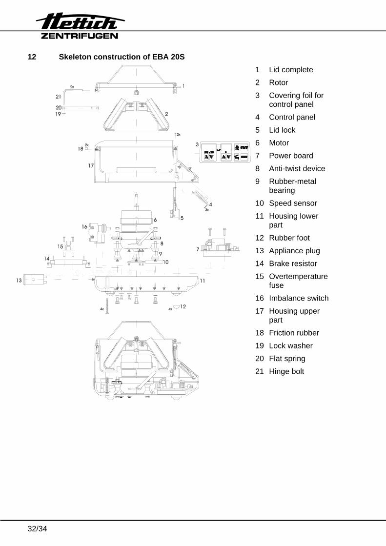
12 Skeleton construction of EBA 20S 1 Lid complete 2 Rotor 3 Covering foil for
control panel 4 Control panel 5 Lid lock 6 Motor 7 Power board 8 Anti-twist device 9 Rubber-metal
bearing 10 Speed sensor 11 Housing lower
part 12 Rubber foot 13 Appliance plug 14 Brake resistor 15 Overtemperature
fuse 16 Imbalance switch17 Housing upper
part 18 Friction rubber 19 Lock washer 20 Flat spring 21 Hinge bolt
33/34
13 Index – 1 – Tacho error..........................................................................................................11 – 2 – System reset ........................................................................................................11 – 3 – Imbalance.............................................................................................................12 – 4 – Communication ....................................................................................................12 – 5 – Overload...............................................................................................................12 – 6 – Overvoltage ..........................................................................................................13 – 7 – Overspeed............................................................................................................13 – 8 – Undervoltage ........................................................................................................13 – 9 – Overtemperature ..................................................................................................14 – c – Controller-Watchdog.............................................................................................14 – d – Lid lock error.........................................................................................................15 – E – Short circuit ..........................................................................................................15 – F – Rotor code............................................................................................................15 Appliance plug...............................................................................................................25 Assembling....................................................................................................................23 Brake adjustment ..........................................................................................................20 Brake resistor ...................................................................................................... 8, 25, 29 Cable colours ................................................................................................................26 Circuit diagram ..............................................................................................................27 Control panel .............................................................................................................7, 24 Controller-Watchdog – c –.............................................................................................14 Description and elimination of errors .............................................................................11 Disassembling ...............................................................................................................23 Enquiries .......................................................................................................................18 Error messages .............................................................................................................10 Flat ribbon cable............................................................................................................25 Functional check ...........................................................................................................22 Imbalance......................................................................................................................12 Imbalance switch................................................................................................. 8, 25, 30 Imbalance switch-off......................................................................................................21 Intermediate voltage......................................................................................................30 Lid lock ............................................................................................................................8 Lid lock control ..............................................................................................................21 Lid lock solenoid............................................................................................................29 Lid lock Y1.....................................................................................................................25 Lid switch.......................................................................................................................29
34/34
Machine version............................................................................................................ 18 Machine-Version-Error .................................................................................................. 16 Mains input fuses .......................................................................................................... 22 Mains switch ................................................................................................................. 25 Motor................................................................................................................... 8, 24, 28 Motor coil ...................................................................................................................... 28 No display ..................................................................................................................... 17 No speed indication ...................................................................................................... 16 Overtemperature fuse ............................................................................................... 8, 25 Overtemperature switch ................................................................................................ 28 Plug assignment............................................................................................................ 27 Power board........................................................................................................ 7, 24, 30 Settings ......................................................................................................................... 18 Signals .......................................................................................................................... 28 Speed sensor...................................................................................................... 8, 11, 24 Test results ................................................................................................................... 28 The lid can not be opened............................................................................................. 17